

Page 1
COMMERCIAL FIN-TUBE ENCLOSURES
MODELS J, JR, R, RR, EM, AND F
INSTALLATION INSTRUCTIONS
GENERAL INFORMATION
Use the following table for recommended numbers of bracket-hanger assemblies for each piece of enclosure.
Element
J-SERIES R-SERIES TBG-SERIES
2 3 4 2 3 4 2 3 4
C-340
C-440
C-540
S-532
S-540
S-832
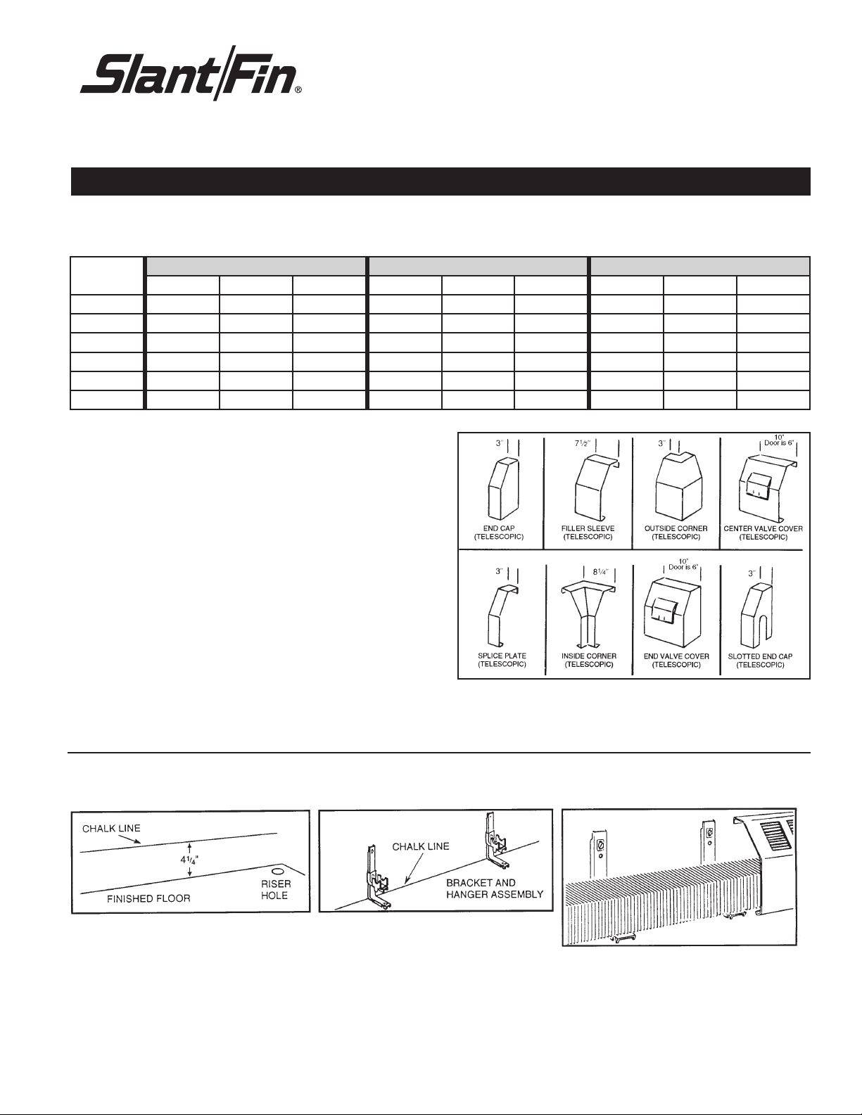
Telescopic accessories
These accessories telescope up to 2” of total length dimension. Wall to
wall dimension, figured at job site, is not effected.
Joining Commercial Enclosures
1. J Series- use internal splice plate to join enclosures together. Internal
Splice plate instructions are in the back of this manual. Generally, use
of external splice plate is not required.
2. R, RR, JR and TBG Series- Use double slip joint to join enclosures.
Joining strip for insertion in double slip joint included and packed
with cover panels. Generally, use of external splice plate is not required.
3. EM and F Series- Use external splice plate to join enclosures.
Damper
When specified, the damper is factory installed except the damper knob
and rod assembly. See instructions in this manual for field installation.
Accessories
JA-14 & JL illustrated: similar accessories available for other enclosures.
2-5 ft. 6-8 ft.
2-5 ft. 6-8 ft.
2-5 ft. 6-8 ft.
–
–
–
2-5 ft. 6-8 ft.
2-5 ft. 6-8 ft.
2-5 ft. 6-8 ft.
2-5 ft. 6-7 ft. 8 ft. 2-4 ft. 5-7 ft. 8 ft. 2-5 ft. 6-7 ft. 8 ft.
2-5 ft. 6-7 ft. 8 ft. 2-4 ft. 5-7 ft. 8 ft. 2-5 ft. 6-7 ft. 8 ft.
2-4 ft. 5-6 ft. 7-8 ft. 2-4 ft. 5-6 ft. 7-8 ft. 2-5 ft. 6 ft. 7-8 ft.
–
–
–
NOTE: When using valve covers, an additional bracket should be
installed at the right or left end of the valve cover for additional
support.
2-5 ft. 6-7 ft. 8 ft.
2-5 ft. 6-7 ft. 8 ft.
2-5 ft. 6-7 ft. 8 ft.
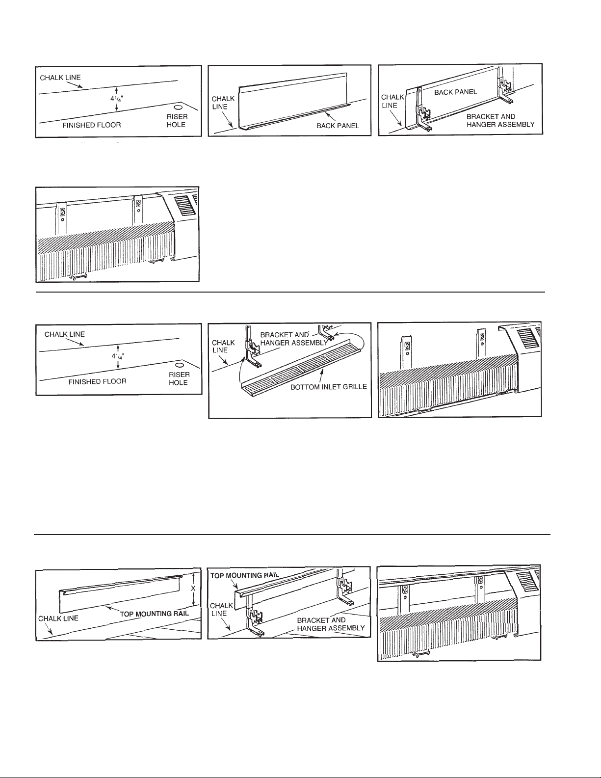
SERIES J & R ENCLOSURES WITHOUT BACK PANEL
STEP 1: STEP 2: STEP 3:
Mark chalk line.
Publication No. CP-40
Part # 00-5175
a) Attach hanger to bracket with Sems
screws furnished (1/4" x 20 x 1/4").
b) Mount assembly to w
c) Align hanger for necessary pitch.
all at chalk line.
a) Install elements, connect and
test system
b) Install cover by inserting the top lip
between wall and bracket. Pull down
and back until bottom lip snaps into
slot on bracket.
c) Follow through with accessories.
Page 2
SERIES J & R ENCLOSURES WITH BACK PANEL
STEP 1: STEP 2: STEP 3:
Mark chalk line, as above.
Install back panel at chalk line
.
a) Attach hanger to bracket with Sems
screws furnished (1/4" x 20 x 1/4").
b) Mount assembly to back panel.
STEP 4:
c) Align hanger for necessary pitch.
a) Install elements, connect and test
system.
b) Insert top lip between wall and back
panel. Pull down and back until
bottom lip snaps into slot on bracket.
c) Follow through with accessories.
SERIES J & R ENCLOSURES
WITH BOTTOM INLET GRILLE
STEP 1: STEP 2: STEP 3:
Mark chalk line.
a) Attach hanger to brac
ket with Sems
screws furnished (1/4" x 20 x 1/4").
b) Mount to wall at chalk line. Leave
bottom screws loose for friction fit of
back edge of bottom inlet grille.
c) Install bottom inlet grille to bracket.
Complete mounting of bracket
a) Install elements, connect and test
system.
b) Snap on cover, insert top lip between
wall and bracket. Pull down and back
until bottom lip snaps into slot on
bracket.
c) Follow through with accessories.
to wall.
d) Align hanger for necessary pitch.
SERIES JR & RR ENCLOSURES WITH 4" TOP MOUNTING RAIL (BPT)
STEP 1: STEP 2: STEP 3:
Attach hanger to bracket with Sems
a) Mark chalk line.
b) Install top mounting rail above chalk
line using the following dimensions:
for enclosures with 1-tier of element
10", 1-tier of element 14", 2-tier 21"
and 3-tier 28".
a)
screws furnished (1/4" x 20 x 1/4").
Mount assemb
b)
ly to back panel.
c) Align hanger for necessary pitch.
a) Install elements, connect and
test system
b) Insert cover in the “V” channel in top
mounting rail. Pull down and back until
bottom lip snaps into slot on bracket.
c) Follow through with accessories.
2
Page 3

DAMPERS
DAMPER KNOB & LEAD SCREW
ASSEMBLY
INSTRUCTIONS
1. Screw LEAD SCREW into LEAD SCREW NUT about 10 turns clock
wise in direction shown.
2. Line up LEAD SCREW with BUSHING hole by sliding DAMPER left or right.
3. Swing DAMPER toward COVER and guide LEAD SCREW through
BUSHING hole until beginning of SCREW thread is against BUSHING and
SCREW EXTENSION protrudes through front of COVER. Hold in place and
proceed to step 4.
4. Place KNOB on to SCREW EXTENSION and line up allen head SET
SCREW in KNOB with FLAT of SCREW EXTENSION and tighten set
screw with an allen wrench.
SERIES EM, F AND BARE ELEMENT
STEP 1: STEP 2: STEP 3:
Mark chalk line.
a) Mount required hanger at chalk line.
b) Align hanger for necessary pitch.
ACCESSORIES
FIT BOTH EM & F COVERS:
TYPICAL ARRANGEMENTS OF ENCLOSURES FOR SERIES J OR R
TYPE EM
TYPE F
a) Install elements, connect and test system
b) Slip on cover, insert top flange of cover
between wall and fins, cover rests on fins.
SERIES EM OR F
3
Page 4

INTERNAL SPLICE PLATE INSTALLATION INSTRUCTIONS
Cover sections may be tightly joined with internal splice plates for a neat, trim fit. They may be used instead of external splice plates.
Step 1:
After installing support brackets on the
wall at the desired height, place the cover
over the brackets and snap in place.
Step 4:
Place the next cover in place on support
brackets.
Step 2:
Insert the internal splice plate just shy of
the halfway slots. Slots must remain
visible and not slide under cover.
Step 5:
Slide the next cover over the internal
splice plate up to the screws, nails or
slotted screw drivers.
Step 3:
Insert screws, nails or slotted screw drivers into
the 2 halfway slots of the internal splice plate to
hold it in the correct location and prevent the
halfway slots from sliding under cover.
Step 6:
Remove the 2 screws, nails or screw
drivers.
Note: Product shown is unpainted and
does not represent finished installation.
Step 7:
Continue sliding cover sections together
until a snug fit is obtained.
©Slant/Fin Corp. 2009 Printed in the U.S.A. 909 Publication No. CP-40
SLANT/FIN CORPORATION, Greenvale, N.Y. 11548 • Phone: (516) 484-2600
FAX: (516) 484-5921 • Canada: Slant/Fin LTD/LTEE, Mississauga, Ontario
www.slantfin.com
 Loading...