

Page 1
EUTECTIC EC-20
OIL-FIRED WATER BOILERS/NO. 2 OIL
ASSEMBLY INSTRUCTIONS
EUTECTIC EC-20 ASSEMBLY GUIDE
©Slant/Fin Corp. 2013 • Printed in the U.S.A. 1113 • Part # 470911000 • Publication No. EC-20-50 Rev.B
Page 2

Package List
8800N043A
8
800N043A
8800N073A
Packaging:
The following table shows the package numbers included with the boiler to be installed.
The packages are presented in the order in which they should be opened for assembly.
EC-20
Contains the boiler instructions Contains the control panel instructions
Boiler Boiler Casting Sub-Assembly Jacket and Insulation
Control Panel
Basic or SF-10 for
EC-20 Series
EC-25 475002000 475009200
EC-26 475003000 4750010200
EC-27 475004000 475011200
EC-28 475005000 475012200
Basic – 475014000
SF-10 – 475299000
Basic – 475014000
SF-10 – 475299000
Basic – 475014000
SF-10 – 475299000
Basic – 475014000
SF-10 – 475299000
2
EUTECTIC EC-20 ASSEMBLY GUIDE
Page 3

1. Fit the adjustable feet to the height converter (The feet are delivered with the screw bag in the jacket and insulation package).
1
Tools required:
• 1 Phillips screwdriver
• 1 Wide flat screwdriver
• 1 13mm open end wrench
• 1 17mm open end wrench
• 1 19mm open end wrench
Step 1– Mounting Feet
Boiler body assembly
EUTECTIC EC-20 ASSEMBLY GUIDE
3
Page 4

Step 2
Step 2
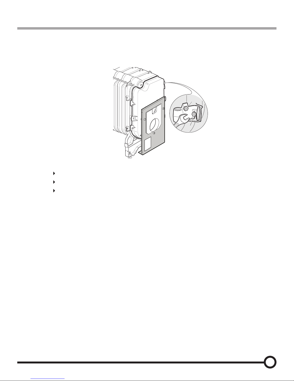
Mounting: Hinged door
Boiler casting assembly is normally shipped with boiler door hinges on the right when viewing boiler from front.
If boiler casting assembly has door removed, it can be mounted with hinges on the right side when viewing from the front
by following the procedure below..
1. Put the lower hinge in place against the front section
2. Secure the lower hinge: 1 screw HM 10x50 + CL 10-20 wide conical washer.
3. To be prefitted to the front section, in the upper hinge position: 1 screw HM 10x50 + CL 10-20 wide conical washer.
4. Hang on the boiler door
5. Put the upper hinge in place and tighten the screw.
6. Fit the H10x20 adjustment screw to the upper hinge.
If you want to mount boiler door with hinges on the left when viewing from the front, then follow the above directions, in
much the same way.
4
EUTECTIC EC-20 ASSEMBLY GUIDE
Page 5
Step 3
To adjust the boiler door, adjust the top hinge:
Untighten screw A
turn the screw B to position the door,
Tighten screw A.
A
B
17
Step 3
Adjusting the boiler door
EUTECTIC EC-20 ASSEMBLY GUIDE
5
Page 6
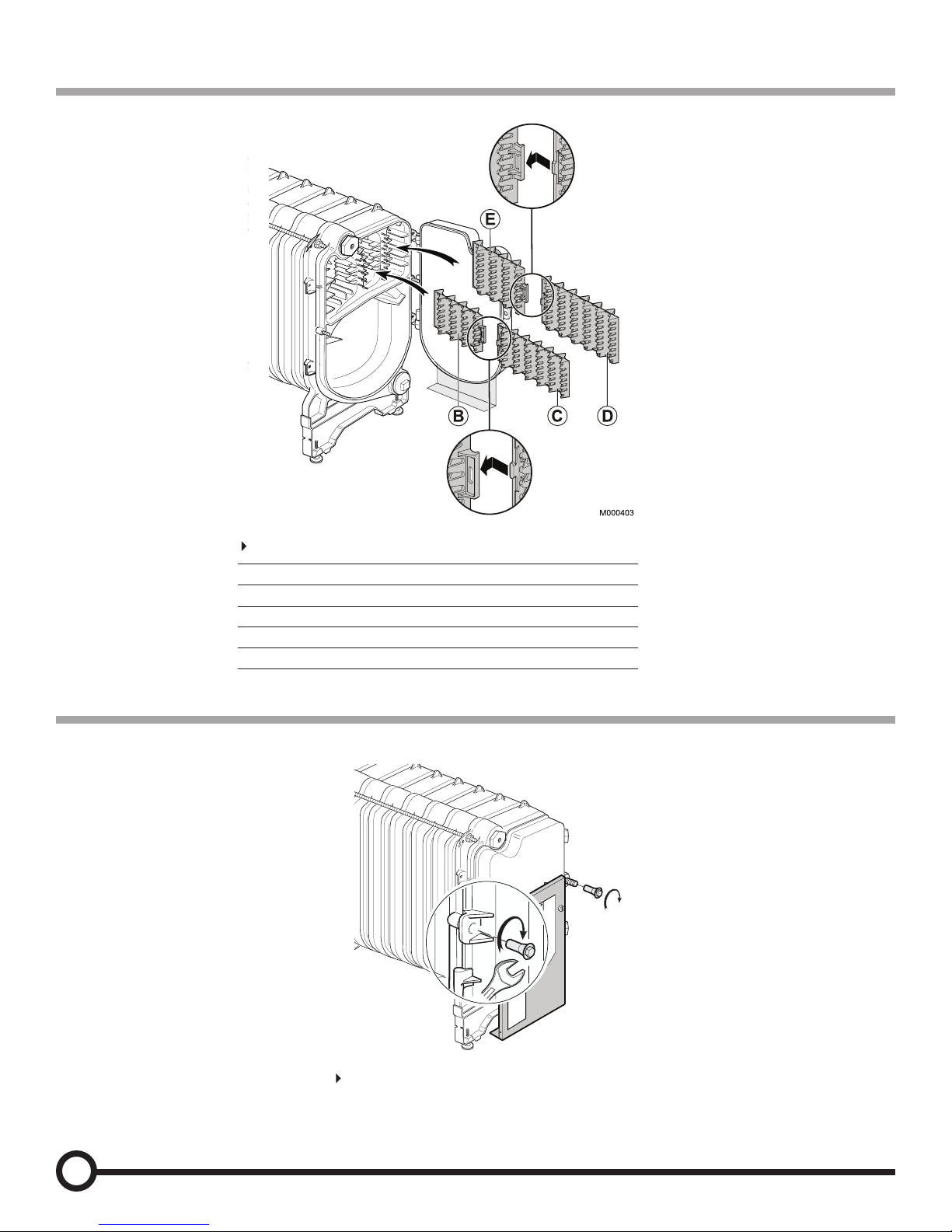
Step 4
Put the baffles in place. Align the convection accelerators with the first fins.
Close the boiler door and tighten using the 2 special nuts.
BCDE
EC-25
XX
EC-26
XXXX
EC-27
XXXX
EC-28
XXXX
82
2
7
N0
2
9A
17
Put the baffles in place. Align the convection accelerators with the first fins.
BCDE
EC-25
XX
EC-26
XXXX
EC-27
XXXX
EC-28
XXXX
Baffles
Step 5
6
EUTECTIC EC-20 ASSEMBLY GUIDE
Page 7

Step 6
Thermatic
Basic
Mounting: Front crosspiece with Basic or Thermatic Control
EUTECTIC EC-20 ASSEMBLY GUIDE
7
Page 8

Step 7
Fitting the body insulation
8
EUTECTIC EC-20 ASSEMBLY GUIDE
Page 9

Step 8
Cable Clamp
Cable routing must come
from left side for right hand
hinge (factory equipped).
To be plugged
into molex plug
on burner.
If hinged door is changed
to left side, cable routing
must be moved to the right.
Push the burner into the burner
d
oor until it will not go any further.
Fix the burner using
hex nuts, supplied.
Note:
After the installation has been
connected and filled with water, star t
the burn er into service following the
instructions supplied with it.
Fix the cable in position using the
cable clamp. Slide the surplus cable
backwards between the insulation and
the front cross piece. Secure cable clamp
and tighten screw after slack is removed
from cable to make sure cable will disconnect when burner door is opened.
– Replace the burner cover.
Fix the gasket with the flange on the burner
door using four 3/8”–16 studs, supplied.
(screw shorter length of metric thread into
burner door.)
4
Assembling the burner
EUTECTIC EC-20 ASSEMBLY GUIDE
9
Page 10

Step 9
Danger
Label
Rating Label
Baffle Label
Attach Burner
Instructions Label
that is packed with
Burner
10
EUTECTIC EC-20 ASSEMBLY GUIDE
Page 11

Step 10
Step 11
Fitting the rear panel
Remove the clean out trap
EUTECTIC EC-20 ASSEMBLY GUIDE
11
Page 12

Fit the rear panel
Step 12
Fitting the rear panel - continued
12
EUTECTIC EC-20 ASSEMBLY GUIDE
Page 13

Step 13
Replace the clean out trap
Replace the clean out trap
EUTECTIC EC-20 ASSEMBLY GUIDE
13
Page 14

- Then, insert the bulbs inside the pocket and maintain them with the spring
Detail A: Basic Control Panels
-Boiler sensor
-Safety thermostat
-Thermometer
-Contact spring (can be found in the boiler instructions bag)
- Detail B: Thermatic Control Panel
-Boiler thermostat
-Boiler sensor
-Safety thermostat
- No contact spring
Step 14
Control panel assembly – Installing sensor bulbs
14
EUTECTIC EC-20 ASSEMBLY GUIDE
Page 15

Step 15
Fitting the front panel - Fitting the top panel
Connect burner hanress to molex connector. Make sure it disconnects when opening door.
See page 9 for adjustment if necessary.
EUTECTIC EC-20 ASSEMBLY GUIDE
15
Page 16

16
EUTECTIC EC-20 ASSEMBLY GUIDE
Page 17

EUTECTIC EC-20 ASSEMBLY GUIDE
17
Page 18

18
EUTECTIC EC-20 ASSEMBLY GUIDE
Page 19

EUTECTIC EC-20 ASSEMBLY GUIDE
19
Page 20

©Slant/Fin Corp. 2013 • Printed in the U.S.A. • Part # 470911000 • Publication No. EC-20-50RevA
SLANT/FIN CORPORATION., Greenvale, N.Y. 11548 • www.slantfin.com
Phone: (516) 484-2600 • Fax: (516) 484-5921
In Canada: Slant/Fin LTD/LTEE, Mississauga, Ontario • www.slantfin.can
 Loading...