

Page 1
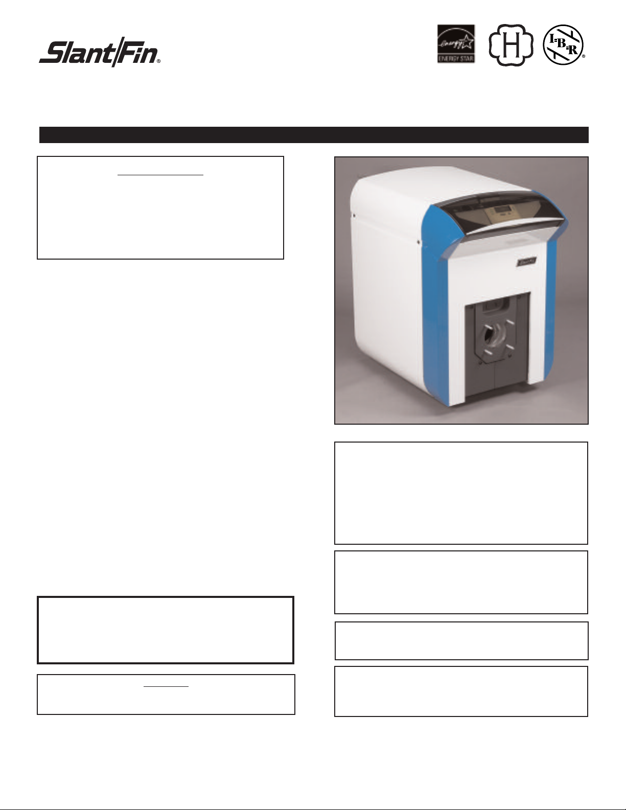
EUTECTIC
EC-10DV Series
DIRECT VENT OIL-FIRED WATER BOILER/NO. 2 OIL
INSTALLATION AND OPERATING INSTRUCTIONS
SAFETY WARNING:
KEEP BOILER AREA CLEAR AND FREE FROM
COMBUSTIBLE MATERIALS, GASOLINE AND
OTHER FLAMMABLE VAPORS AND LIQUIDS.
FAILURE TO ADHERE TO ABOVE SAFETY
WARNING, MAY RESULT IN PERSONAL INJURY
OR DEATH AND PROPERTY DAMAGE.
CONTENTS . . . . . . . . . . . . . . . . . . . . . . . . . . . . . . . . .PAG E
Ratings and Dimensions . . . . . . . . . . . . . . . . . . . . . . . . . . .2
Installation Requirements:
Boiler Location . . . . . . . . . . . . . . . . . . . . . . . . . . . . . . . .3
Clearances . . . . . . . . . . . . . . . . . . . . . . . . . . . . . . . . . . .3
Vent Requirements . . . . . . . . . . . . . . . . . . . . . . . . . . . . .3
Vent Piping . . . . . . . . . . . . . . . . . . . . . . . . . . . . . . . . . . .3
Installing Water trim . . . . . . . . . . . . . . . . . . . . . . . . . . . .3
Installing Burner . . . . . . . . . . . . . . . . . . . . . . . . . . . . . . .4
Oil Supply Piping . . . . . . . . . . . . . . . . . . . . . . . . . . . . . .5
Wiring the Boiler . . . . . . . . . . . . . . . . . . . . . . . . . . . . . . .5
Operating Instructions:
Precautions Before Starting . . . . . . . . . . . . . . . . . . . . . .5
Start-up . . . . . . . . . . . . . . . . . . . . . . . . . . . . . . . . . . . . . .5
Cleaning and Filling New Water Boiler . . . . . . . . . . . . . .5
Wiring Diagrams . . . . . . . . . . . . . . . . . . . . . . . . . . . . .6-7
Burner Data:
Riello . . . . . . . . . . . . . . . . . . . . . . . . . . . . . . . . . . . . . .8-9
Care and Maintenance:
Extended Shutdo
Freezing Protection . . . . . . . . . . . . . . . . . . . . . . . . . . . .10
Oil Burner . . . . . . . . . . . . . . . . . . . . . . . . . . . . . . . . . . .10
al Maintenance . . . . . . . . . . . . . . . . . . . . . . . . . .
Gener
THIS BOILER OPERA
THE FLUE AND OVER FIRE, ALL SEALS MUST BE IN
PLACE WHEN OPERATING THE BOILER. ALL VENTING
MUST BE INSTALLED AND SEALED ACCORDING TO THE
VENT MANUFA
wn . . . . . . . . . . . . . . . . . . . . . . . . . . .
TES WITH POSITIVE PRESSURE IN
CTURER’S INSTRUCTIONS
.
10
10
IMPORTANT: The installation of this equipment must conform
to the requirements of the authority having jurisdiction or, in
the absence of such requirements, to the Installation of Oil
ning Equipment, ANSI/NFPA 31, latest edition, and to the
Bur
National Electrical Code ANSI/NFPA 70, latest edition. The
installation must also conform to the additional requirements in
this Slant/Fin Instruction Manual. Where there is any difference, the more stringent requirement shall govern.
In addition, where required by the authority having jurisdiction,
the installation must conform to American Society of
Mechanical Engineers Safety Code for Controls and Safety
vices for A
De
edition.
THIS MANUAL MUST BE LEFT WITH OWNER AND
SHOULD BE HUNG ON OR ADJ
utomatically Fired Boilers, No. CSD-1, latest
BOILER FOR REFERENCE.
CENT
A
THE
O
T
UTION
CA
The information in this manual must be followed exactly
to avoid personal injury, property damage or loss of life.
IMPORTANT: This boiler must be installed by a trained,
ienced, ser
xper
e
vicing of oil b
and ser
the author
vice technician, licensed f
ning equipment or otherwise qualified by
ur
ities having jurisdiction over the installation.
Part No. 470908000 Publication No. EC-10DV-40
or the installation
Printed in U.S.A. 407
Page 2
2
1
-1/4 threaded
s
upply
Flue outlet øD
1
-1/4 threaded
r
eturn pipe
D
rain outlet
R
elief valve 3/4’’
Supply Pipe Mounted
T
ridicator
P
anel Mounted
Tridicator Pressure
Sensor Well
Panel Mounted
Tridicator Temperature
S
ensor Well
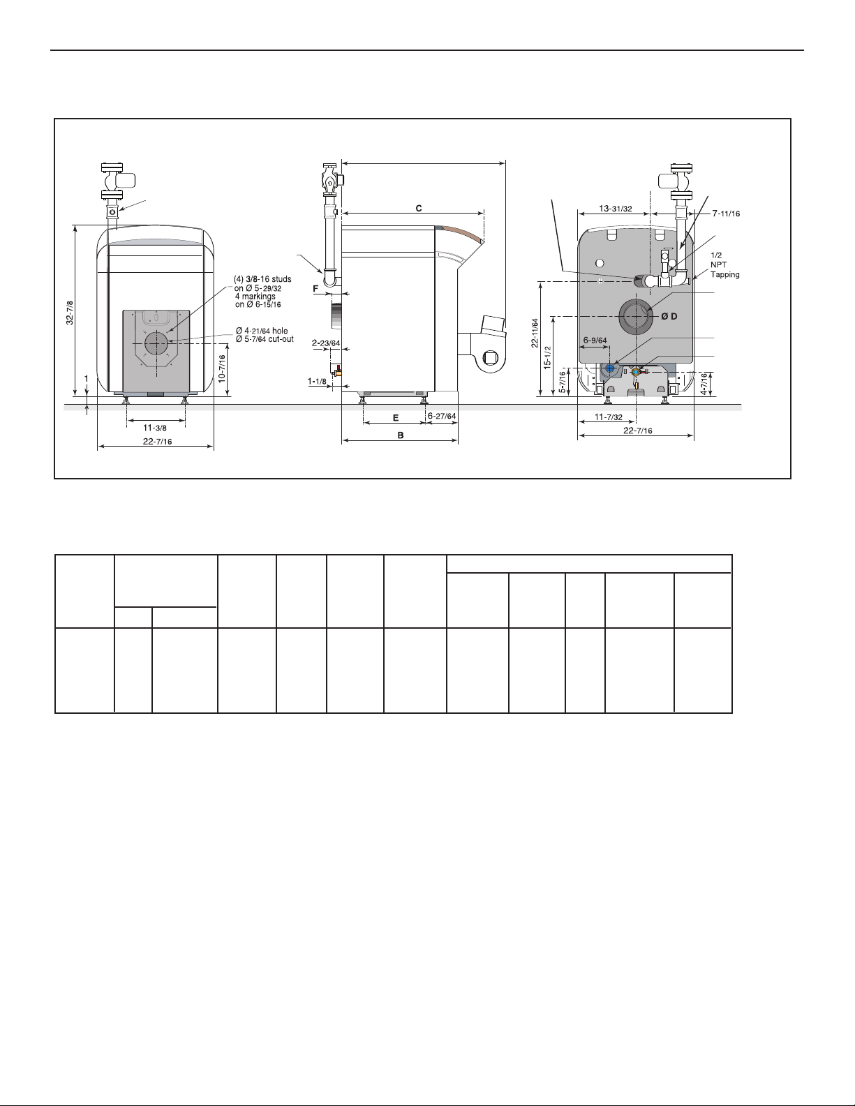
A
Figure 1: Dimensions (inches)
EUTECTIC EC-10 DV
TABLE 1: Ratings and Dimensions
BOILER
MODEL
NO.
I=B=R
BURNER
CAPACITY
OIL INPUT †
GPH BTUH
D.O.E.
HEATING
CAPACITY
MBH *
WATER
I=B=R
WATER
NET
RATING
MBH *
AFUE %
APPROX.
OVERALL
LENGTH
“A”
BOILER
LENGTH
“B”
DIMENSIONS (inches) #
BOILER
LENGTH
“C”
FLUE
DIA.
“D”
DISTANCE
BETWEEN
LEGS
“E”
OUTLET
LENGTH
EC-13DV 0.65 91,000 79 69 87 36 22-1/4 27 5 11-13/16 2
EC-14DV 0.80 112,000 98 85 87 41 27-1/4 32 5 16-13/16 2
EC-15DV 1.00 140,000 123 107 87 46 32-1/4 37 5 21-13/16 2
EC-16DV 1.15 161,000 141 123 87 51 37-1/4 42 6 26-13/16 4
Maximum operating pressure 60 psi.
All boilers h
ydrostatically tested — A.S
.M.E.
* For forced hot water heating systems where the boiler and all piping are
located within the area to be heated, the boiler may be selected on the basis
capacity output. The net I=B=R output ratings shown are based on
.E.
of D.O
an allowance for piping and pickup of 1.15 (water). D.O.E. capacity output is
divided by the allowance to obtain net rating. The Slant/Fin Technical Service
department should be consulted before selecting a boiler for unusual piping
and pickup requirements such as intermittent system operation, extensive
piping, etc.
† Ratings apply to the use of light oil at 140,000 Btu per gallon and apply only
ner models listed on pages 8 of this manual are used, and are
ur
when b
properly adjusted to produce 13% CO2.
ufacturing tolerance.
All dimensions subject to nor
#
mal man
NOTE: All boilers under 300,000 Btuh (87.9 kw) input are tested and rated for
capacity under the U.S. Depar tment of Energy (D.O.E.) Test Procedures for
Boilers.
FLUE
“F”
Page 3
UTECTIC EC-10 DV
E
3
I
NSTALLATION REQUIREMENTS
BOILER LOCATION
Provide a level, solid foundation for the boiler.
A. The foundation must be capable of supporting the weight of
the boiler when filled with water:
Boiler Approximate Total Weight of Boiler
Size Assembly*, filled with water
EC-13-DV 353
EC-14-DV 426
EC-15-DV 501
EC-16-DV 575
* Includes burner, circulator and controls
B. These boilers have full wet base sections which surround firebox for maximum heat absorption of burning fuel, and low floor
temperature.
. If boiler is to be located over buried conduit containing electric wires
C
or telephone cables, consult local codes or the National Board of Fire
Underwriters for specific requirements.
MINIMUM CLEARANCE
Provide accessibility clearance of 24" from surfaces requiring servicing (top
and front) and 18" on any side requiring passage. The boiler shall be
installed with the following MINIMUM clearances from combustible materials:
BACK AND SIDES- 6"
NOTE: Except in closets and alcoves, clearances above in (A) and
(B) may be reduced by providing forms of protection as specified in
NFPA 31, latest edition.
VENTING REQUIREMENTS
• The terminal shall not be closer than 3 feet above or 10 feet horizontally from any forced air inlet into the building.
• The terminal shall not be closer than 4 feet below, 4 feet horizontally
or 1 foot above any door, window or gravity air inlet into the building.
• The terminal shall not be less than 3 ft from an inside corner of an “L”
shaped building.
• The terminal shall not be less than 7 ft above grade when located
adjacent to public walkways.
• The terminal shall not be less than 2 ft from an adjacent building.
• The terminal shall be located at a height not liable to blockage from
leaves, snow or other debris, at least 1 ft above grade or anticipated
snow line.
• The terminal shall be positioned so that flue gases are not directed
where they can jeopardize people, overheat combustible structures
or enter buildings.
• Vent terminal should be away from shrubbery or other obstructions
that would prevent free air flow to and from vent terminal. Do not ter-
ent under dec
minate v
locations under windows should be avoided.
mination should not be mounted directly abo
ent ter
V
•
horizontally from an oil tank vent.
, stairways or car ports. When ever possible,
ks
e or within 3 ft
v
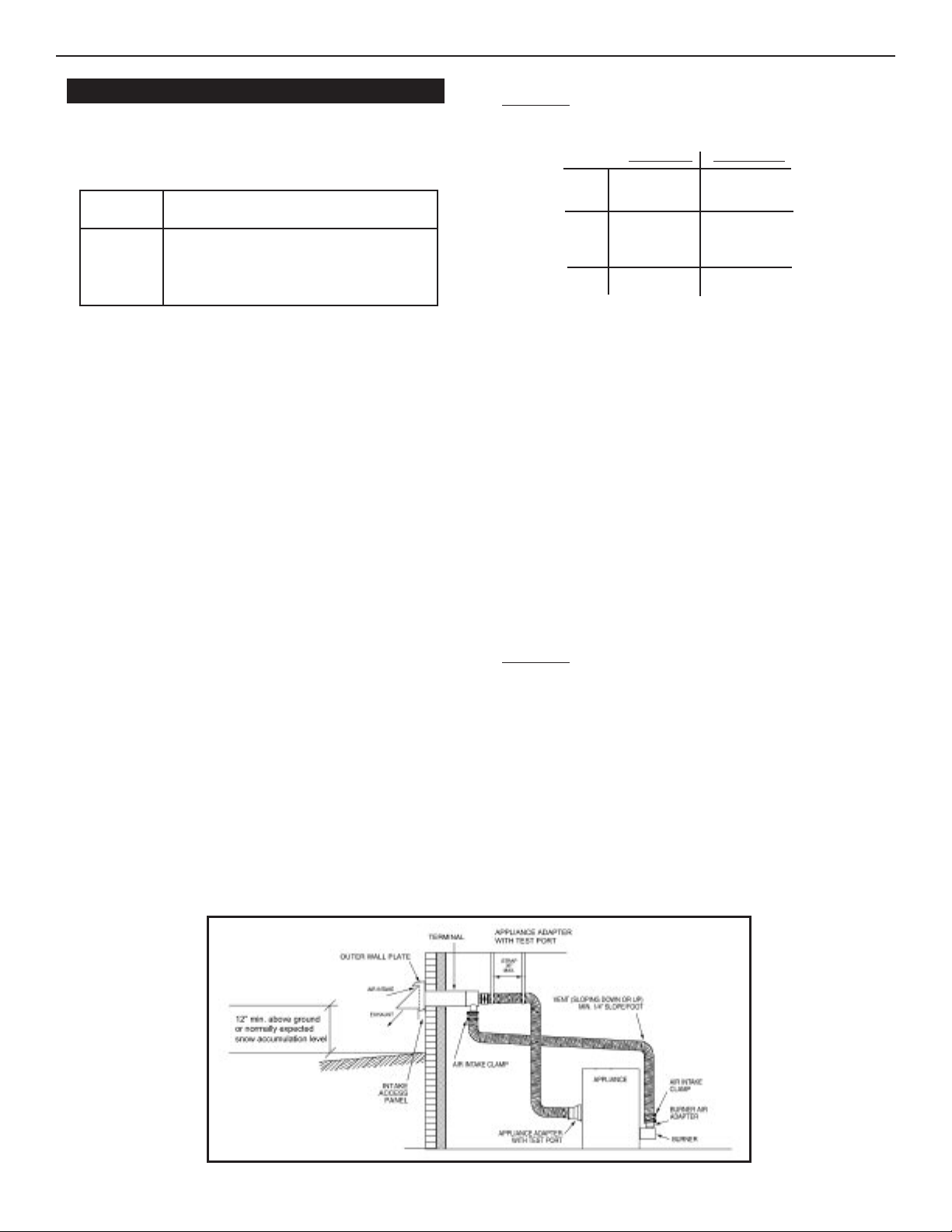
BOILER INTERNAL BAFFLES
TANT: EC-10 series boilers Direct Vent version is different from
IMPOR
standard series. Direct Vent version boilers usually have fewer internal cast
iron baffles.
E
E
C-14 & 15
EC-16
C-13
e
S
rsion
tandard V
(
3) Baffle Plates
(
2) Baffle Plates
c
enter & right side
when viewing from
front
(0)
e
nt Version
D
irect V
(
2) Baffle Plates center
& right side when
viewing from front
(
0)
(0)
VENT PIPING
A. The vent piping minimum bend radius is 12”.
B. Place metal strapping every 36” to support vent pipe and prevent it
from sagging.
C. Maximum wall thickness is 14”. Contact Slant/Fin Corp. for
recommendations in case of thicker wall.
D. Gases will form white plume in winter. Plume could obstruct window view.
E. Prevailing winds could cause freezing of condensate and water/ice
buildup on building, plants or roof.
. Locate or guard vent to prevent accidental contact by people or pets, and
F
condensate from damaging exterior finish.
G.Do not terminate vent in window well, stairwell, alcove, courtyard, or other
recessed areas.
All venting kits must be double wall construction for the flue gas piping.
Field
Controls is the only approved manufacturer for venting kits. When installing
the vent kits the manufacturers instructions must be followed.
I
NSTALLING WATER TRIM
Notes: Jacket must be installed on boiler units prior to installation of trim.
PIPING
IMPORTANT: Boilers are to be used with closed system. Any application
that uses water from system, causes the introduction of a frequent supply of
fresh water into the boiler. This will cause damage to the boiler. Use of heat
exchangers will prevent this damage.
PIPING FOR WATER UNITS
NOTE: On knock down boiler only, jacket may be installed after return piping connection, but must be installed prior to adding trim & supply piping.
I. CIRCULATING SYSTEM
A. FORCED CIRCULATION hot water heating system: Use the top
tapping as supply tapping, and use the rear bottom tappings for
the return.
B. A FLOW CONTROL VALVE will prevent gravity circulation.
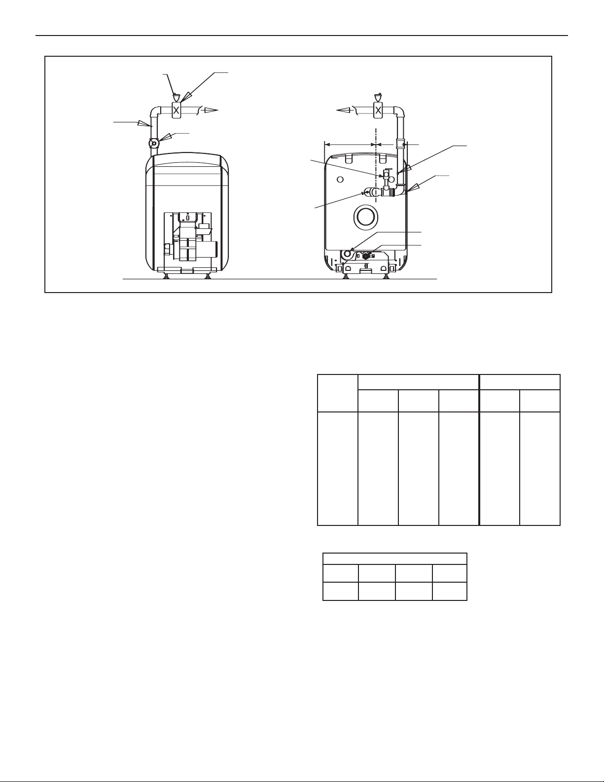
II. AIR CONTROL SYSTEMS
A. DIAPHRAGM-TYPE COMPRESSION TANKS are used to control
system pressure in an AIR ELIMINATING SYSTEM: an automatic
air vent is used to REMOVE air from the system water. See figure 3.
Figure 2. Typical Installation
Page 4
4
1
3-31/32
7
-11/16
Relief valve 3/4
1/2” NPT Tapping
for Feed Valve and
E
xpansion Tank
1-1/4 NPT
r
eturn tapping
Drain outlet
Panel Mounted
T
ridicator Temperature
Sensor Well
A
ir Eliminator
a
s per Manufacturer
Specifications
To Circ. (s)
and Zones
1
-1/4”
NPT
Supply
Automatic
Air Vent
S
uppy Pipe Mounted
Tridicator
Panel Mounted
Tridicator Pressure
Sensor Well
Figure 3. Air Eliminating System or Alternating Collecting System
EUTECTIC EC-10 DV
If system pressure needs further control, add an additional tank or install a
larger capacity tank. The automatic air vent should be installed in the top of
the boiler, as in figure 3.
B. CONVENTIONAL COMPRESSION TANKS (non-diaphragm type) are
used to control system pressure in an AIR COLLECTING SYSTEM. Within
the system, after initial start-up and venting, air is collected in the tank and
acts in contact with the water to control pressure. Air is not vented from this
system. If system pressure needs further control, add another tank in
parallel with the original tank or install a large capacity tank. Locate the
tank at the inlet end of the pump near the boiler. (See figure 3)
C. HOT WATER RADIATION VENTING - Manual air vents should be installed
at the top of all "drops" (where piping goes downward). Air must be vented
or purged from all zone lines to permit proper system heating.
D. PUMP LOCATION - Locating low-head pump(s) on return to boiler is
acceptable for smaller boiler sizes in residences of one or two stories.
The pump location sho
wn in figure 3 is required in large
, m
y
ulti-stor
building installations, especially when high-head pumps are used.
IMPORTANT: Hot water heating systems containing high water volume, such
ould occur with cast iron r
as w
adiation, require special care with air elimination. The circulator pump should be located on the boiler supply pipe and the
expansion tank and air scoop should be located near the pump suction.
INSTALLING THE BURNER
ner Data, pages 8-9, and Bur
See Bur
ner Man
ual supplied with b
ur
ner. If
burner is not mounted as received, mount to boiler, placing flange over
mounting studs
flange and nose of burner must be as shown on pages 8-9. Check to see
. Use gasket between flange and boiler. Distance between
that nozzle and settings are as given in burner data tables, pages 8-9.
VOLUME OF WATER IN STANDARD PIPE OR TUBE
Standard Steel Pipe Copper Pipe
⁄
4
⁄
2
⁄
2
Pipe
Schedule
40 0.622 0.0157 0.545 0.0121
40 0.824 0.0277 0.785 0.0251
40 1.380
40 1.610 0.106 1.505 0.0924
40
40 2.469 0.249 2.465 0.248
Nominal
pipe Dia.
3
⁄
8
1
⁄
2
5
⁄
8
3
⁄
4
1 40 1.049 0.0449 1.025 0.0429
1
1
1
1
2
1
2
Pipe ID
Inch
Gal. per
Lin.Ft.
Pipe ID
Inch
Gal. per
Lin. Ft.
– – – 0.430 0.0075
– – – 0.666 0.0181
1.265 0.0653
1.985 0.161
2.067
0.0779
0.174
3 40 3.068 0.384 2.945 0.354
WATER CONTENT OF BOILER (GALLONS)
EC-13 EC-14
5 6.5 8 8.5
EC-15 EC-16
Page 5

UTECTIC EC-10 DV
E
5
OIL SUPPLY PIPING
Install the oil tank or tanks and piping from tank to burner. Follow local
codes and practices, NFPA No. 31, INSTALLATION OF OIL BURNING
EQUIPMENT and the instruction sheet attached to the oil burner pump. A
one-pipe system should be used for gravity fed fuel systems and for lift systems, where the total lift is less than 8 ft. Where the total lift is greater than 8
ft., a two-pipe system must be used. In some instances, local codes may
require a two-pipe system for below grade fuel oil tanks. Be sure to set-up
the fuel oil pump for the piping system used; follow the instructions attached
to the pump. Be sure to include a good quality, low pressure drop fuel oil filter in the supply line from the tank. This is necessary, especially at low fuel
oil flow rates (small nozzle sizes), to prevent nozzle plugging.
WIRING THE BOILER
• The wiring diagrams for the burner and boiler may be found on pages 6-7.
• 24 volt control wiring should be approved Safety Circuit wire, protected
as needed.
• Power supply wiring to the burner must be 14 gauge or heavier, as
required, and should have a properly fused disconnect switch. 120 volt
wiring to pumps and safety controls must also be 14 gauge or heavier.
ust be enclosed in approved conduit.
Wire m
• All wiring must be installed in compliance with the National Electric
Code, or any local or insurance codes having jurisdiction.
OPERATING INSTRUCTIONS
PRECAUTIONS BEFORE STARTING OIL BURNER
Make a positive check of A through I before starting burner:
A. Boiler and system are full of water. All air is vented from system.
See below.
B. All wiring is completed. See pages 6-7.
C. Oil supply is connected to the burner; nozzle is installed correctly; oil
valve is open at tank.
D. All combustible materials are cleared away.
E. All vent piping is properly installed and sealed.
F. Burner settings are adjusted as per pages 8 & 9 and as shown on
boiler jacket label.
G. Main cast iron door on which burner is mounted is bolted shut and
fiberglass rope seal is making good contact.
H. Make sure boiler has correct quantity of baffles (see bottom of pag 3).
I. Make sure vent pipe, vent terminal and air supply pipe are properly
installed and clear of obstruction.
Note: Neither overfire nor flue draft should
exceed 0.35" WC during burner operation
CLEANING AND FILLING A NEW WATER BOILER
I. BEFORE FILLING WATER BOILER
A. Check burner to be certain it is ready for firing. DO NOT FIRE
into an empty boiler.
B. Be prepared to heat raw water to at least 180°F. as soon as it is
introduced into the boiler. This procedure will remove dissolved,
corrosive gases.
C. Provide drain line, with valve, from boiler. Use a bottom tapping.
Line and drain must be suitable for handling caustic solution.
II. CLEANING WATER BOILER SYSTEM
A. Use a commercial cleaning solution, such as
9100 Cleaner as directed in product instructions.
B. Use a commercial treatment solution, such as
Treatment as directed in product instructions.
III. FILLING AND VENTING THE WATER BOILER
A. Refill the system with fresh water.
B. Bring water temperature to at least 180° F. promptly.
C. Circulate water through entire system.
D. Vent the system, including the radiation.
E. The boiler is now ready to be put into service or on standby.
. If brand-name air-control devices are used, venting instructions
F
furnished with the devices should be followed.
IV. SAFETY CHECK FOR CONTROL SYSTEM
High limit control test: Set thermostat high enough for boiler water
ature to reach high limit control setting. When this temperature is
temper
reached, the high limit switch should open, and the burner should shut off
automatically. If the high limit does not operate to shut off the burner, the
high limit or the wiring is faulty. Repair or replace immediately.
Rhomar Hydro-Solv
Rhomar Pro-Tek 922
START-UP (COMBUSTION TEST INSTRUMENTS MUST
BE USED) THIS BOILER IS A POSITIVE PRESSURE BOILER.
A. Make sure the boiler is installed and wired properly and is full
of water.
B. The observation port cover is mounted on the hinged burner
mounting door. NEVER touch the port cover or any surrounding
surfaces with hands. They may be HOT. Use tools. Loosen the
screw and swing cover to be able to insert probe through slot,
when necessary. See the burner instructions for bleeding air, etc.
C. Take a smoke reading soon after starting burner. If smoke is not
zero or trace, open air to clear smoke and let burner fire.
D. DO NOT ATTEMPT TO SET FIRE BY EYE. A smoke gun and a
combustion analyzer must be used. Adjust the air to get approximately 12% C
O
2
ero or trace smoke. Then check and
with a z
record draft and flue temperature.
ation port cover is closed tight, the
Make sure that the obser
E.
urner is secure. Turn burner on and off at least 3 times to
b
v
check ignition.
THE FLUE IS UNDER POSITIVE PRESSURE DURING
OPERATION. ALL VENTING MUST BE SEALED AND
CHECKED ON A REGULAR INTER
VAL.
Page 6

6
Honeywell L 7248C–1030 Aquastat Control Single Zone Wiring
EUTECTIC EC-10 DV
Page 7

UTECTIC EC-10 DV
E
7
Honeywell L 7248C–1030 Aquastat Control Multiple Zoned (Circulator or Zone Valve)
Page 8

8
EUTECTIC EC-10 DV
RIELLO BURNER DATA
Riello
Burner
odel
Boiler Model
EC-13DV BF-3 Long 0.65 0.55 80*A Delavan 133 0 4.5 2 7"
EC-14DV BF-3 Long 0.8 0.7 80*B Delavan 130 3 5.5 none 7"
EC-15DV BF-5 Short 1 0.75 60*A Delavan 178 1 4.4 none 4-1/4"
EC-16DV BF-5 Short 1.15 0.85 60*W Delavan 182 2 4.2 none 4-1/4"
M
Blast
ube
T
Firing
Rate
PH
G
Size
GPH)
(
Nozzles
Angle &
Type
M
fg.
Oil Pump
PSIG)
(
Approx.
Head
etting
S
Approx.
Air
etting
S
Boile
Flue
affle
B
Models BF-3 & BF-5 Electrode Setting
Figure 4.
Burner
Insertion
epth
D
Turbulator location
3
2
1
Picture 1.
TURBULATOR SETTING
Loosen n
1.
2. Retighten the retaining nut, 1.
The numbers on the casting are there to denote the high and lo
scale indicators only. From left to right, the first line is 4 and the last line is 0.
ut, 1, then turn the screw, 2, until the index marker, 3, is aligned with the correct index number.
w end of the scale – F
or Model BF-5, zero and four are
The air/oil ratio depends on accurate setting of the turbulator disc and air damper.
Be careful when making this adjustment as an incorrect setting will result in an unsatisfactory operation.
See figure 5 & 6.
Page 9

UTECTIC EC-10 DV
E
9
Figure 5. Model F-5
Figure 6. Model F-3
SETTING THE AIR DAMPER ADJUSTMENT (see figure 7 & picture 2)
1. The initial air damper setting is made by turning screw (2) until the top edge of the air damper (3) is aligned with the
number according to the burner setup chart.
2. Further adjustments can be made with the burner cover in place by removing plastic plug on the top right hand side
of the cover. Turn the screw counter clockwise (+ indicator) to increase combustion air, turn the screw clockwise ( indicator) to decrease combustion air.
3. The final position of the air damper will vary on each installation. Use instruments to establish the proper settings
for maximum CO2 and a smoke reading of trace to zero.
NOTE: Variations in flue gas, smoke, CO2 and temperature readings may be experienced when the burner cover
is put in place. Therefore, the burner cover MUST be in place when making the final combustion instrument
readings, to ensure proper test results.
2
1
Figure 7. Air Damper Setting
Picture 2. Air Damper Location
3
Page 10

0
1
EUTECTIC EC-10 DV
CARE AND MAINTENANCE
I. EXTENDED SHUTDOWN, CLEANING OR REMOVAL OF
OILER FROM SERVICE.
B
DANGER: Use CAUTION when handling chemicals and
ining hot water from a boiler
dra
chemicals can cause permanent injury to the skin, eyes
nd respiratorysystem.
a
A.Shut down burner by disconnecting all electrical power to
the burner by turning OFF the BURNER EMERGENCY
SWITCH of this boiler. After shutting down burner, while
he boiler is still hot (180°F to 200°F), drain water from
t
the bottom of the boiler until it runs clear.
B.Provide corrosion protection conditioning to the boiler water
in the heating system. There are a number of commercial
heating system preparations available from your distributor.
Follow the preparation manufacturer’s instructions.
o clean the fireside boiler surfaces, first shut down
C.T
burner by disconnecting all electrical power to the burner
by turning OFF the OIL BURNER EMERGENCY
SWITCH of this boiler in order to perform the following
work in (1) through (10) below.
1. Remove the flue pipe from the boiler flue collar and
clean thoroughly.
2. Inspect the entire vent connector back to the chimney and clean if necessary.
3. Inspect the chimney for soot, debris and other unsafe
conditions of the chimney and take the necessary
action.
4. The burner mounting door must be fully open to
clean the flue passages and the combustion
chamber
be disconnected from the burner during the cleaning
process. The flexible electric conduit connected from
the junction box on the boiler to the burner via a
plastic connector must be disconnected from the
burner by grasping the plastic half of the connector
closest to the flexible conduit and gently pulling it in
the direction of the conduit until it is disconnected.
Remove all four 13 mm hex head screws on the
sides of the s
open end or box wrench. Open the door to
completely e
thorough cleaning and f
iron burner door insulation and burner door fiberglass
sealing rope.
5. Use the flue br
iron baffle plates for cleaning [(2) baffle plates in EC13, (0) baffle plates in EC-14, 15, and EC-16.]† A wire
brush may be used to remove any carbon accumulation that may ha
ber
Replace baffle plates.
6. Inspect the burner combustion head. Clean if necessary and make sure all the adjustments are correct.
(See b
Replace oil nozzle with new one and readjust electrodes. To insure proper burner operation ONLY THE
NOZZLES SPECIFIED IN THIS MANUAL OR ON
THE BURNER LABEL SHOULD BE USED FOR
REPLACEMENT.
† A flue brush (triangular shape) is supplied with boiler.
. If the oil line is not flexible enough it should
winging door.You will need a 13 mm
xpose the comb
ush to clean the fluew
e de
v
acuum the loose soot and debris from the boiler.
V
.
ner data pages f
ur
calding water and/or
. S
ustion chamber for
or inspection of main cast
. Remove cast
ys
a
eloped in the combustion cham-
v
or the burner installed.)
. Protect all of the fireside surfacesby swabbing with
7
neutral mineral oil.
8. Close main cast iron b
burner is mounted). Make sure that the entire seal
fiberglass rope) is making good contact with the
(
boiler casting when replacing four 13 mm hex head
crews and tightening.
s
D.If boiler room is damp, provide ventilation.
II. PROVIDING PROTECTION FOR FREEZING
Anti-freeze is sometimes used in hydronic heating systems to protect against freeze-up in the event of power
failure, or safety control shutdown when the building is
unoccupied. It should be recognized that unless the building is kept above freezing temperature by some means,
the plumbing system is not protected.
PROPYLENE GLYCOL is used in the quick-freeze food
industry; it is practically non-toxic. Its use may be permitted
when indirect water heaters are used. When anti-freeze
must be used, inhibited propylene glycol is recommended.
Useful information on the characteristics, mixing proportions, etc. of glycol in heating systems is given in Technical
Topics No. 2A, available from the Hydronics Division of
GAMA, 35 Russo Place, Berkeley Heights, NJ 07922.
Consult glycol manufacturers for sources of propylene
glycol.
DO NOT USE ETHYLENE GLYCOL BECAUSE IT IS TOXIC.
III. OIL BURNER
Inspect and clean annually and following any period of
improper operation. Recheck and adjust settings as specified for burner model and nozzle size.
Set burner air using test instruments to obtain recommended CO
page in this manual that corresponds to the burner
installed.
IV. GENERAL MAINTENANCE
These operations are recommended to be performed at
regular intervals:
A.BOILER HEATING SURFACES: clean off all coatings
B.BOILER CONTROLS: check settings, correct functioning.
C.PIPING: check piping and accessories for leaks.
D.STUB VENT and BREECHING: check for obstructions
E.COMBUSTION AIR TO BURNER: check for continued
F
G.BOILER ROOM AIR SUPPLY: air vents should be open
and draft without smoke. See the Burner Data
2
found. Reseal covers.
and leaks.
POSITIVE supply of air as required. Air needs are greatest in coldest w
page 3.
ATER SYSTEM: check
W
.
1. System to be full of water and pressure to remain
stable (between 12 psi and 25 psi).
Air-control system:
2.
should not occur
3. Water lines: slightest leaks should be corrected.
and free of obstr
eather.
uction.
urner door (door on which
er to AIR SUPPL
Ref
noise and air binding in r
.
,
Y
adiation
Page 11

SLANT/FIN CORPORATION, Greenvale, N.Y. 11548 • Phone: (516) 484-2600
(516) 484-5921 •
AX:
F
Canada:
Slant/Fin
L
TD/L
TEE,
Mississauga, Ontar
www
.slantfin.com
io
 Loading...