

Page 1
EUTECTIC EC-10
OIL-FIRED WATER BOILERS/NO. 2 OIL
ASSEMBLY INSTRUCTIONS
Tools required:
• 1 Phillips screwdriver
• 1 Wide flat screwdriver
• 1 13mm open end wrench
• 1 19mm open end wrench
©Slant/Fin Corp. 2014 • Printed in the U.S.A. 1214 • Part # 470901000 • Publication No. EC-10-50 Rev.B
Page 2
2
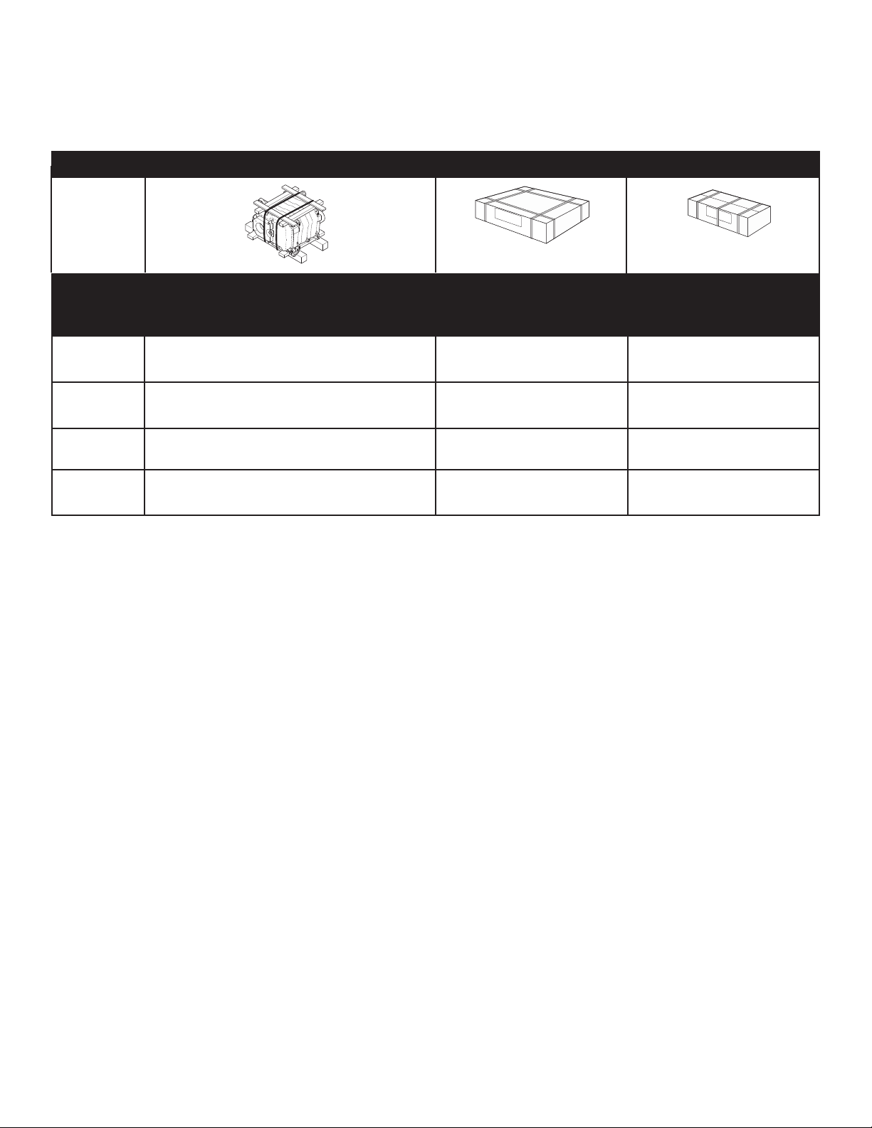
Boiler Boiler Casting Sub-Assembly Jacket and Insulation
Control Panel
Basic or S/F-10
for EC-10 Series
EC-13 470001000 470008200
Basic – 470014000
SF-10 – 470299000
EC-14 470002000 470009200
Basic – 470014000
SF-10 – 470299000
EC-15 470003000 470010200
Basic – 470014000
SF-10 – 470299000
EC-16 470004000 470011200
Basic – 470014000
SF-10 – 470299000
Contains the boiler instructions Contains the control panel instructions
Packaging:
The following table shows the package numbers included with the boiler to be installed.
The packages are presented in the order in which they should be opened for assembly.
EC-10
The assembly of any options delivered with the boiler is described in the instructions accompanying the options.
The list of available options is indicated in the price list in force.
Page 3
3
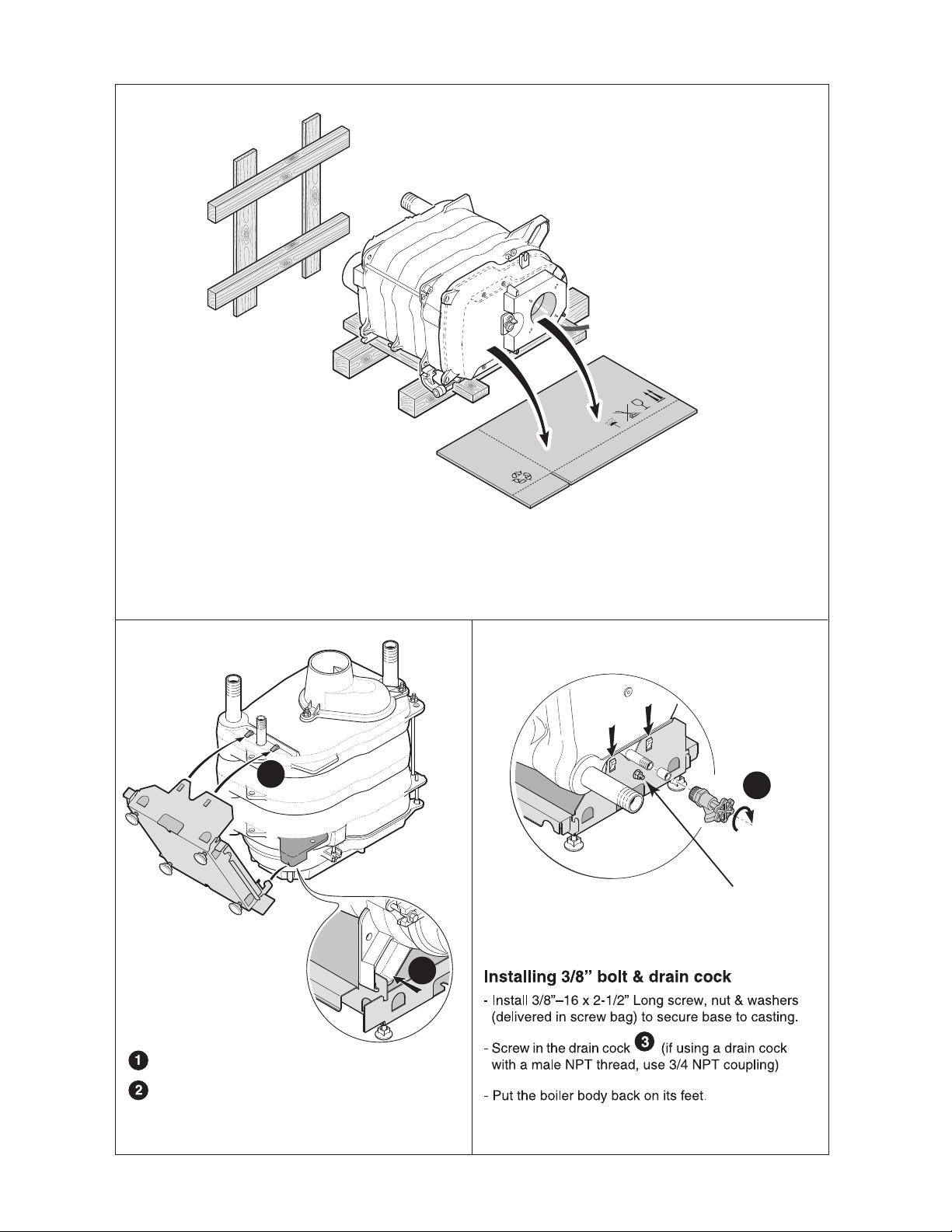
1
Put a protective piece of cardboard on the floor in front
of the boiler casting sub-assembly.
Take the body off the pallet and put it down vertically on
the burner door.
Packagees
2
1
Installing the base
Attach the base onto the front of the boiler.
Clip the base onto the rear section.
32
3
3/8” Bolt, Nut & Washers
Page 4
4
3
4
3
5
4
4.2
4.3
8575N018
8575N019
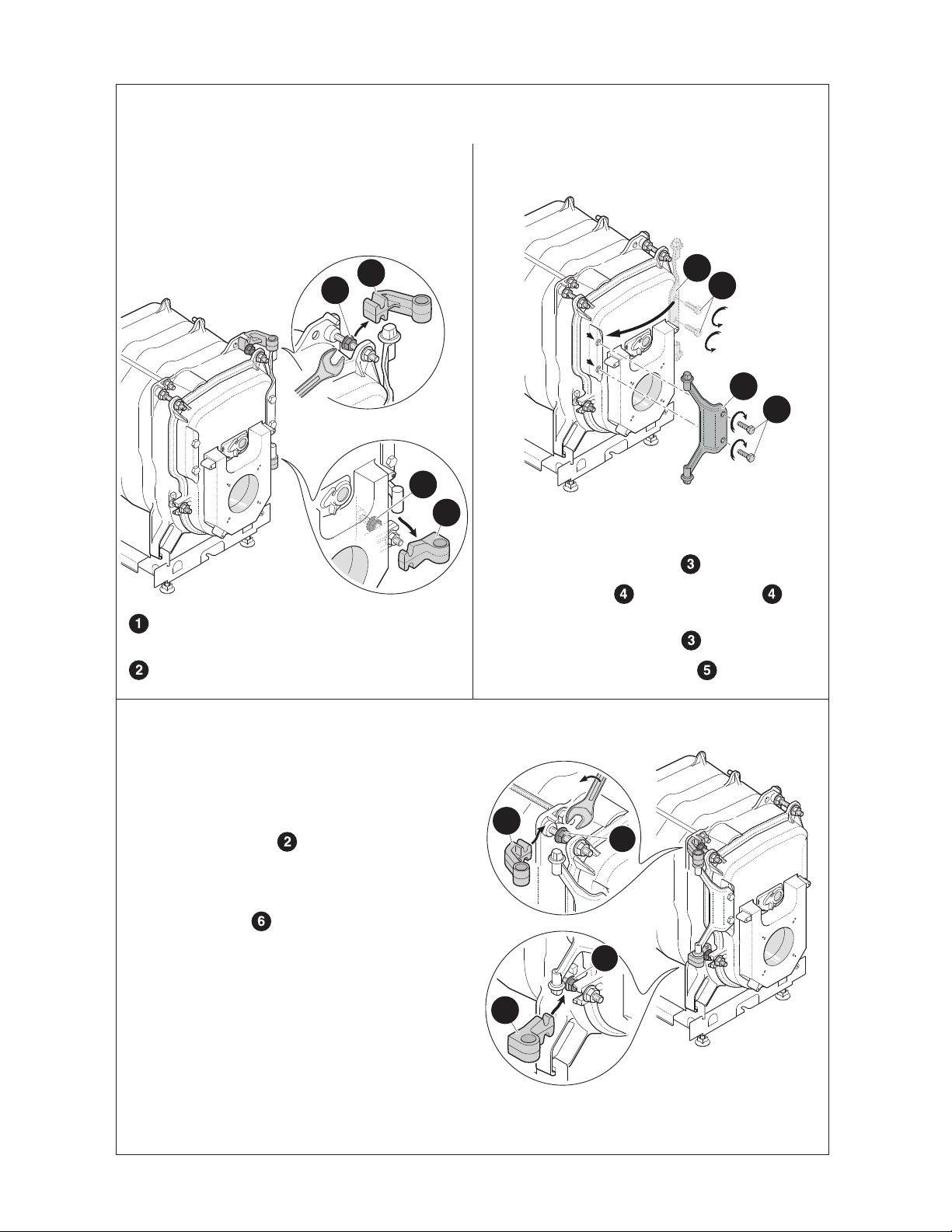
Loosen the 2 top and bottom nuts.
Remove the lower and upper hinges.
8575N020
13
1
2
1
2
- Remove the cast iron hinge pin for the burner door
fixed by the 2 screws . Put the two screws back
on the right-hand side
- Reinstall the cast iron hinge pin for the burner door
on the left side using the 2 screws .
Reverse the direction of opening of the burner door if necessary
(opening at left).
2
6
2
6
- Reinstall the hinge pins on the left side, fixing them
using the nuts located on the burner door hinge pins, on
the left side, as shown on the adjacent figure.
- Tighten the 2 nuts .
4.1
When the burner leaves the factory, the burner
door opens towards the right. Perform operations
4.1, 4.2 and 4.3 below to open the burner door
towards the left (if absolutely necessary).
Page 5

5
5
6
8575N021A
- Pass the strap between the cast iron body and the base.
- Install the insulation around the body, folding the bottom on each side of the boiler inside the base.
1
2
8575N022
Installing the insulating material
3
2
1
Fix the insulation using the strap(s) and the attach-
ment strip .
- Put the back insulation into place and fix it onto the pre-
viously installed insulation using the fasteners .
notch in front
- 1 strap on the 3 and 4 section versions,
- 2 straps on the 5 and 6 section versions
Page 6

6
85
75
N
023
B
1
4
5
6
3
6
2
1
4
7
8
8575N024
9
10
10
7
8
- Put the rear cross bar into place on the lugs of the rear
section facing the outside of the boiler positioning it on:
• the assembly rod ,
• the rear section positioning pin .
- Fix on the rear section with 1 HM8 x 30 screw + 2
flanged nuts .
Installing the control panel support cross bar
- Put the support cross bar into place on the boiler body,
positioning it on :
• the M8 studs at the front,
• the assembly rod and the 3rd section positioning pin
- Fix it at the front with 2 HM8 flanged nuts .
- Fix the 3rd section with :
• 1 HM8 x 30 screw + flanged nuts ,
• 1 flanged nut on the assembly rod.
Assembling the back cross bar (EC-15/16)
Only on 5 and 6 section boilers
EC-13
EC-14
EC-15
EC-16
Page 7

7
9
Putting the burner cable in place
Attach one end of the burner wiring harness (cable)
to control box, and route other end through hole in control
panel support cross bar. (Shown with Honeywell aquastat
control.)
Attach cable clamp (from bag of screw) to cable to
limit travel of cable through hole in control panel support
cross bar. (Cable clamp will need adjustment when installing burner.)
Cable clamp.
Honeywell Aquastat
Cable
Page 8

8
10
Put the front of the side panel into place, engaging
the lower notch of the panel in the cross bar of the base.
Make sure that the lower fold in the panel is cor-
rectly positioned under the fold of the cross bar.
Straighten the side panel and pull it upwards.
Attach the side panel to the lugs of the control panel
support, pulling its upper fold upwards such that the
upper fold of the side panel is centred and blocked between the two notches.
Fix the side panels using 2 self tapping screws +
serrated washers.
5
4
1
1
3
3
1
2
8575N025B
Installing the side panels
Page 9

9
11
Installing the rear panel
Hang up the rear panel on the side panels.
Fix it using four self tapping screws + serrated
washers delivered in the fasteners pack.
Installing the front burner door panels
Fix the two front burner door panels using four RLS
M6 x 10 black screws (delivered in the screw bag).
2
2
1
1
8575N449A
12
8575N031D
2
2
1
Installing the cover
Put the cover into place and push it forwards to
fix it in the two side panel bushings.
Fix it at the back with 2 ø 3.94 x 12.7 screws +
2 ø 4 serrated washers.
8575N032A
13
black screws
Page 10

10
Push the burner into the burner
door until it will not go any further.
Fix the burner using four washers
and hex nuts, supplied.
Note:
After the installation has been
connected and filled with water, start
the burner into service following the
instructions supplied with it.
Connect the connector into the
burner connector after having secured
the burner.
Adjust the cable length so that the burner cable has to be disconnected to
open the burner door.
Fix the cable in position using the
cable clamp and the 2 ø 3.5 x 25
screws.Slide the surplus cable backwards between the insulation and the
side panel. Secure cable clamp after
slack is removed from cable to make
sure cable will disconnect when burner
door is opened.
- Replace the burner cover.
4
Assembling the burner
14
8575N
239B
1
Fix the gasket with the flange on the burner
door using four 3/8”–16 studs, supplied.
(screw shorter length of metric thread into
burner door.)
To be plugged
into molex plug
on burner.
Cable routine must come
from left side for right hand
hinge (factory equipped).
5
If hinged door is changed
to left side, cable routing
must be moved to the right.
Cable clamp.
Page 11

11
16
Final levelling of the boiler
- Level the boiler by adjusting its adjustable feet (preinstalled on the base).
(1) basic height 1”,
adjustment range : 1” – 1-9/16”
N
5758
A5
3
0
1”
(1)
19
19
1”
(1)
15
Assembling the front cap
Lift the window.
Attach the front cap in the openings near the bot-
tom of the side panels.
Slide the two lugs of the front cap into the notches
of the side panels and then fix it in the two spring clips.
Push the front cap into contact with the side panels
and fix it using the two black RLS M 6 x 10 screws
(S/F part no. 470128000) (delivered in the casing screw bag).
4
2
1
3
3
4
Page 12

17
1
Stick the nameplate and other labels on the side of the boiler.
Rating plate.
Place “DANGER” label as shown, near front.
Place nozzle spec/burner set up procedure,
near front as shown.
Place “Installing Boiler Label” near rear as shown.
3
4
Place “ETL” label where shown.
5
2
4
5
SLANT/FIN CORPORATION., Greenvale, N.Y. 11548 • www.slantfin.com
Phone: (516) 484-2600 • Fax: (516) 484-5921
In Canada: Slant/Fin LTD/LTEE, Mississauga, Ontario • www.slantfin.can
©Slant/Fin Corp. 2014 • Printed in the U.S.A. 614 • Part # 470901000 • Publication No. EC-10-50 Rev.B
 Loading...