

Page 1
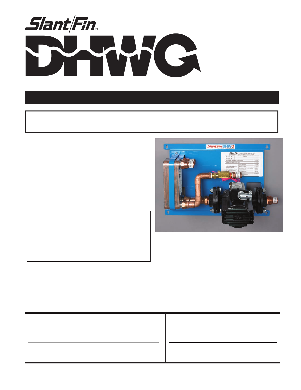
INSTALLATION INSTRUCTIONS
D O M E S T I C H O T W A T E R G E N E R A T O R
DHWG designed for use with Slant/Fin Bobcat and Lynx series
and other similar boilers with DHW priority control capabilities.
Contents Page
Components Included . . . . . . . . . . . . . . . . . . . . . . . . . 2
Dimensions & Specifications . . . . . . . . . . . . . . . . . . . . 3
Wall Mounting Instructions. . . . . . . . . . . . . . . . . . . . . . 3
Water Piping . . . . . . . . . . . . . . . . . . . . . . . . . . . . . . . 3-4
Electrical Wiring . . . . . . . . . . . . . . . . . . . . . . . . . . . . . . 5
System Settings . . . . . . . . . . . . . . . . . . . . . . . . . . . . . . 5
Warning - Hot Water Can SCald!
A tempering valve is recommended to be installed on
the hot water outlet to all fixtures where direct user contact can be made with the water supplied by the DHW
system, to prevent any possible scalding conditions. See
Figure 3 for the appropriate installation method of this
device (not supplied with the DHWG system).
Heating Contractor
Address
Phone Number
Printed in U.S.A. 111 PUBLICATION DHWG-40
Part No. 67 5025
Model Number
Serial Number
Installation Date
Page 2
DHWG Domestic Hot Water Generator
Installation Instructions
Use these instructions in conjunction with the boiler Installation and Operating
Instructions (publication BA-40 for Bobcat and LX1-40 for Lynx boilers) for utilizing this
domestic hot water generator with the boiler.
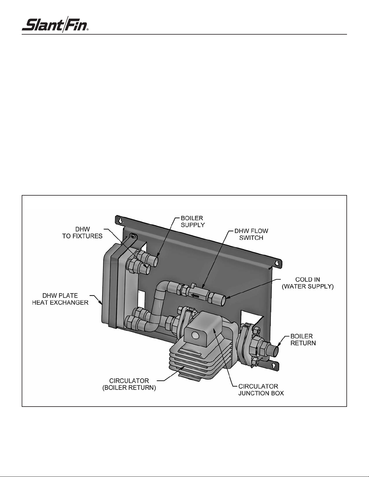
Components included:
1. See Figure 1 for the identification and location of each component and piping
connection provided in the DHWG system.
2. The DHWG pump is sized for the required flow rate through the plate exchanger
to provide adequate hot water production.
3. A flow switch is provided to detect any flow of domestic water, and will energize
the DHWG pump and give a call for the burner to operate as required for the demand.
4. DHWG pump provided has integral flow check, to prevent water flow in
the DHW boiler loop when it is running for space heating demand.
Figure 1. Components and piping of DHWG.
2
Page 3

DHWG Domestic Hot Water Generator
Dimensions:
Width = 17" Height = 12" Depth = 83⁄8"
Specifications:
Weight (empty) = 21 lbs
Water content = 0.2 gallons
Piping connections = 3/4" nom. I.D. copper
Min. DHW flow = 0.3 gpm
Max. working pressure = 125 psi
Mounting to a Wall:
1. DHWG must be installed with water pipes at right or left
side of the unit (see figure 2).
Figure 2.
2. Be sure that the wall is vertically plumb, and capable
of carrying the weight of the DHWG system and all
associated piping, when full of water. See the
specifications above.
3. The system may be mounted onto a combustible wall,
but the water piping must be kept a minimum of 1” away
from any combustible materials.
4. For stud type walls, be sure that there are studs available
in the desired location, and the appropriate fasteners are
utilized for the wood or metal stud type and weight
capacity.
5. For masonry walls, utilize anchors of the appropriate
design for the material and weight capacity.
6. Do not attempt to support the system with anchors driven
into sheetrock only.
Table 1. DHWG pressure drop vs. flow
Temp.
rt –˚F
100
80
70
60
55
Table 2. DHWG temperature rise vs. water flow*
LX-85A
Boiler
1.4
1.8
2.1
2.5
2.8
DHWG Flow Rate–GPM
LX-90
Boiler
1.6
2.0
2.3
2.7
3.0
B-120A or LX-120
Boiler
2.0
2.5
3.0
3.5
4.0
LX-150
Boiler
2.3
3.3
4.0
4.5
5.0
B-200A
Boiler
2.5
3.75
4.75
5.75
6.5
3
Page 4

DHWG Domestic Hot Water Generator
DOMESTIC HOT WATER GENERATOR
DHWG
Water Piping:
1. Make all piping connections to and from the DHWG system
as shown in Figure 3.
2. Isolation valves and unions are recommended on all
piping connections to the DHWG system, to facilitate any
possible service needs. Use full port valves to insure
proper water flow through the system.
3. The piping to and from the boiler should be kept as short
as possible, with a minimum number of restrictions, such
as elbows. The diameter of the piping must not be
reduced from the DHWG system’s provided connection size.
4. The piping for the domestic water in and out should be
adequately sized for the desired flow rates at each
fixture. The distance to each fixture should be considered,
for the response rate of adequate hot water to each.
5. Refer to the boiler manual “Water Piping” section, for
proper installation of the space heating system and all
other piping.
CAUTION: A tempering valve is recommended to be installed
on the hot water outlet to all fixtures where direct user contact
can be made with the water supplied by the DHWG system to
prevent any possible scalding conditions. See Figure 3 for the
appropriate installation method of this device (not supplied with
the DHWG system).
Figure 3. Water piping from boiler to DHWG system (Bobcat B-120A shown)
4
Page 5

DHWG Domestic Hot Water Generator
Electrical Wiring:
1. Make all wiring connections to the DHWG system as
shown in Figure 4.
2. Wire the DHWG system circulator’s junction box leads
to
the boiler’s “DHW CIRC” line voltage terminals. Use 14
gage conductors in BX or conduit, secured to the
connectors provided (See figure 5).
3. Wire the DHWG system water flow switch to the
boiler’s “DHW T-STAT” low voltage terminals. (terminal
#3 and #4 of boiler low voltage terminals, See figure 5).
4. Refer to the boiler manual’s “Electrical Wiring”
section, for proper installation of all additional wiring
necessary for the space heating system and operation
of the boiler.
System Settings:
Refer to the boiler manual’s “Boiler Control and Display
Features”, in the “Operating Instructions” section, for
setting the boiler parameters properly to operate with the
DHWG system.
1. The domestic hot water post pump time (see Table 5 of
the boiler manual) should be set for the minimum value
of 1 second, when the alternating letter indication of
“P-d” is selected.
2. The domestic hot water mode must be set for # 2
(see Table 5), when the alternating letter indication of
“d-t” is selected.
3. The priority mode must be set for 0, DHW priority with
no time limit (see Table 5), when the alternating letter
indication of “b-t” is selected.
4. Set all other parameters as appropriate for the space
heating system and operation of the boiler.
Figure 4. Wiring DHWG system to the Bobcat or Lynx boilers.
5
Page 6

DHWG Domestic Hot Water Generator
TO TERMINAL #3 AND 4
ON BOILER'S LOW VOLTAGE
TERMINALS
TO DHW CIRCULATOR
TERMINALS ON BOILER
LINE VOLTAGE TERMINALS
Figure 5. Electrical wiring connections
6
Page 7

DHWG Domestic Hot Water Generator
NOTES
7
Page 8

©Slant/Fin Corp. 2011. Printed in the U.S.A. 111. Publication No. DHWG-40
SLANT/FIN CORPORATION, Greenvale, N.Y. 11548 • Phone: (516) 484-2600
FAX: (516) 484-5921 • Canada: Slant/Fin LTD/LTEE, Mississauga, Ontario
www.slantfin.com
 Loading...