

Page 1
This manual must be left
®
C US
with owner and should be
hung on or adjacent to the
boiler for reference.
HIGH EFFICIENCY FIRETUBE
CONDENSING GAS BOILER
MODELS CHS-85 through CHS-399
– APPENDIX A –
CONTROLLER AND DISPLAY INSTRUCTIONS
IMPORTANT
READ ALL OF THE FOLLOWING WARNINGS AND STATEMENT
SYMBOLS AND DEFINITIONS BEFORE READING THE
INSTALLATION INSTRUCTIONS
DANGER
!
Danger Sign: Indicates a hazardous situation which,
if not avoided, will result in serious injury or death.
WARNING
!
Warning Sign: Indicates a hazardous situation which,
if not avoided, could result in serious injury or death.
CAUTION
!
Caution Sign plus Safety Alert Symbol: Indicates a hazardous situa-
tion which, if not avoided, could result in minor or moderate injury.
CAUTION
Caution Sign without Safety Alert Symbol: Indicates a hazardous
situation which, if not avoided, could result in property damage.
NOTICE
Notice Sign: Indicates a hazardous situation which, if
not avoided, could result in property damage.
WARNING
!
This Boiler must be installed by a licensed and trained Heating Technician or the Warranty is Void. Failure to properly install thisunit may re-
sult in property damage, serious injury to occupants, or possibly death.
©Slant/Fin Corp. 2013 • 813 • PUBLICATION CHS-CD-40
Page 2

Table of Contents
1.0 INTRODUCTION ........................................................................................................................... 1
1.1 Clearing a Lockout .................................................................................................................... 1
1.2 Keypad ....................................................................................................................................... 1
1.3 Home Screen ............................................................................................................................. 2
2.0 I-INFORMATION SCREEN (MAIN MENU) ................................................................................ 4
2.1 Quick Start ................................................................................................................................. 5
2.2 Login ......................................................................................................................................... 6
2.3 Test ............................................................................................................................................ 6
2.3.1 Forced Rate ................................................................................................................... 7
2.3.2 Manual Burner and Pump Operation ............................................................................ 8
2.4 Advanced Setup ......................................................................................................................... 9
2.4.1 CH Config .................................................................................................................. 10
2.4.1.1 CH Config – CH Config ............................................................................. 10
2.4.1.2 CH Config - Outdoor Reset Config ............................................................ 12
2.4.1.3 CH Config - Warm Weather Shutdown ...................................................... 13
2.4.2 DHW Config .............................................................................................................. 14
2.4.3 Lead Lag Config ......................................................................................................... 15
2.4.3.1 Lead Lag Master Config ............................................................................. 16
2.4.3.2 Use of 4-20mA Input .................................................................................. 17
2.4.3.3 Lead Lag Slave Config ............................................................................... 18
2.4.3.4 Lead Lag Outdoor Reset ............................................................................. 19
2.4.4 System Config ............................................................................................................ 20
2.4.4.1 System ID & Access ................................................................................... 20
2.4.4.2 Pump Config ............................................................................................... 22
2.4.4.3 Statistics Config .......................................................................................... 23
2.4.4.4 High & Stack Limits ................................................................................... 24
2.4.4.5 System Config ............................................................................................. 25
2.4.5 Modulation Config ..................................................................................................... 26
2.4.6 Delta T & T-rise Limits .............................................................................................. 27
2.4.7 Frost Protection Config .............................................................................................. 28
2.4.8 Burner Control Ignition and Timings & Rates ........................................................... 29
2.5 Diagnostics .............................................................................................................................. 30
2.5.1 History ........................................................................................................................ 31
2.6 Display Setup .......................................................................................................................... 32
Page 3
1
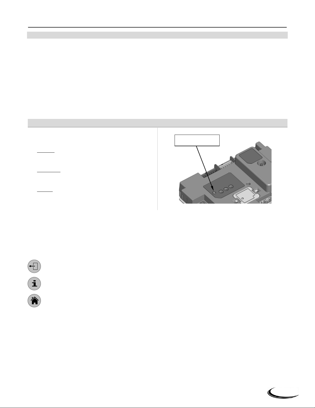
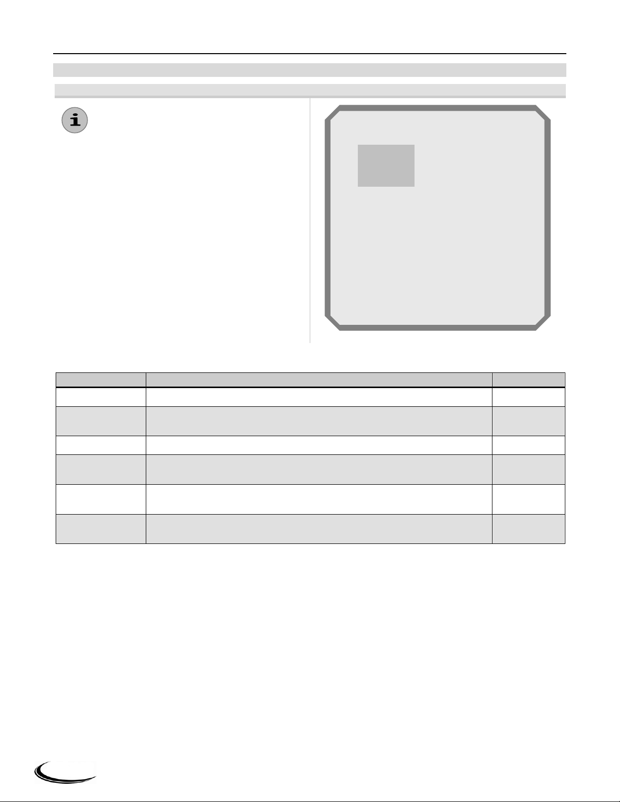
Clearing a Lockout – Any of the following methods
can be used to clear a Lockout:
1. Display - Clear the lockout from the display Home
Screen; press “OK” button on the keypad (see
Figure 1-2).
2. Controller - Clear the lockout by pressing the
RESET button situated on the boiler controller near
the indicator lights (see Figure 1-1).
3. Switch - Cycle power to the boiler using the power
on/off switch situated on the display console.
Reset Button
CHS Series Controller and Display │Slant Fin Corp.
1.0 INTRODUCTION
The Controller and Display, together, form the control system of the Slant/Fin CHS boiler. All control
configuration parameters are stored in non-volatile memory in the CHS controller. Access to controller status
and configuration is achieved with the display. Interaction with the display is performed by physically touching
the buttons on the display keypad. Communication between the CHS controller and display is via EIA-485
interface using the Modbus RTU protocol.
When the appliance is powered there is a brief interval while the display retrieves data from the boiler control.
The display then shows the Home Screen (Summary screen) similar to the one depicted in Figure 1-2. The Home
Screen provides a summary of the overall operational status of the boiler. A series of menus, entered by pressing
the “i-Information” button, provide access to all boiler configuration parameters, information and diagnostics.
1.1 Clearing a Lockout
Figure 1-1 Clearing a Lockout
1.2 Keypad
See Figure 1-2 and Table 1-1 for a complete description of the functions of each keypad button.
Directional Arrow Buttons – are used to quickly navigate through the menu structures and within each
individual screen.
OK Button – Confirms/enters an item selection.
Back Button – returns the user to the previous screen.
i-Information Button – accesses the Main Menu where all control settings, diagnostics, etc are accessed
Home Button – immediately returns the display to the Home Screen.
via a series of sub-menus.
Page 4
2
Analog Sensors I/O
Digital I/O
Outlet temp
Inlet temp
Delta T
DHW temp
Stack temp
Outdoor temp
Fan speed
Flame signal
Firing rate
4-20mA input
System sensor
70 oF
70 oF
1 oF
OPEN
71 oF
OPEN
LOW
0.00 A
0 RPM
OPEN
Outlet
Boiler pump (B)
CH pump (C)
DHW pump (A)
Blower/HSI
Eternal ignition
Pilot valve
Main valve
Alarm
Interlock (ILK)
Pre-ignit interlock (PTI)
Load control input (LCI)
STAT (Demand)
Time Of Day
Safety relay
off
off
off
off
off
off
off
off
on
off
off
off
off
off
7
1 2 3
6
4
5 9 8
10
11
12
13
Slant Fin Corp. │Controller and Display CHS Series
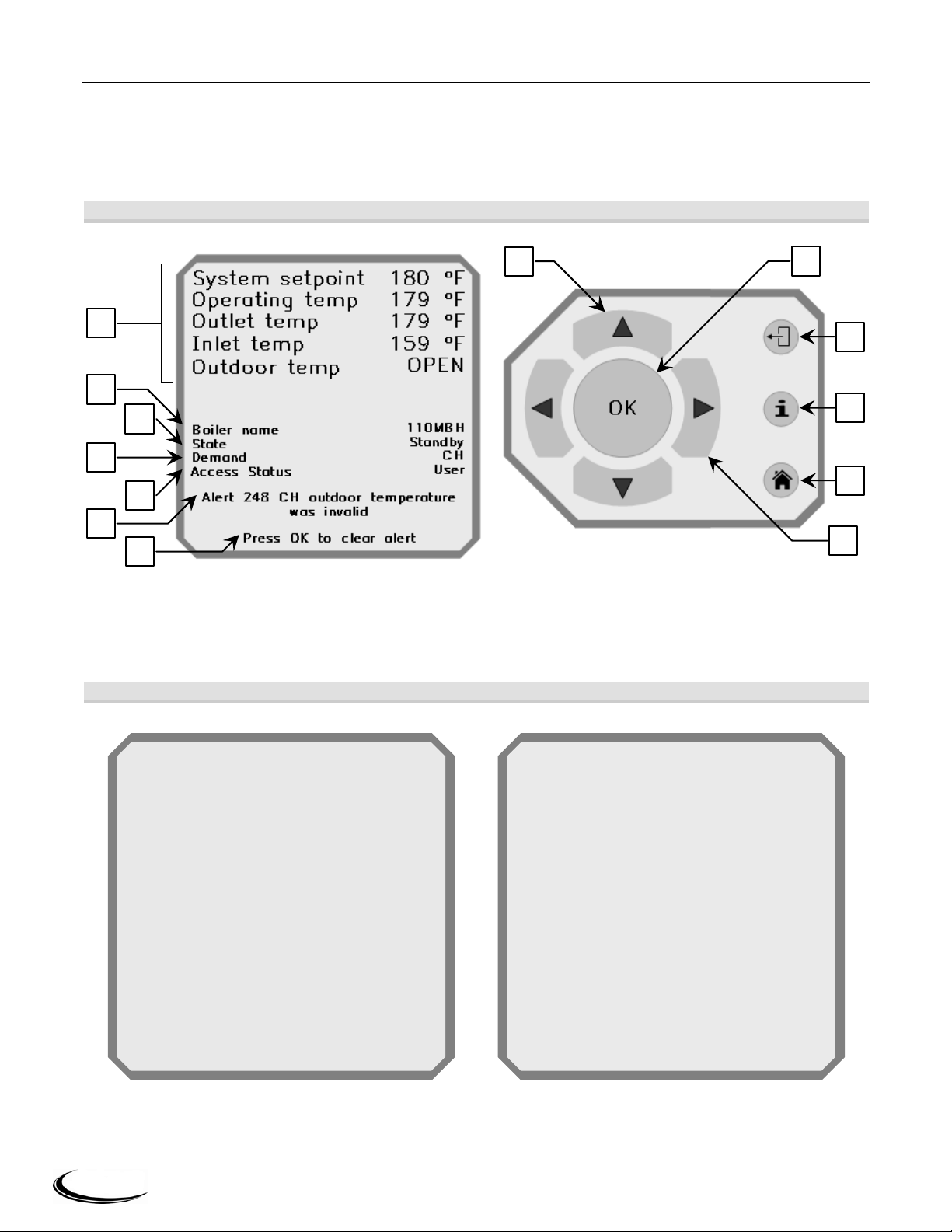
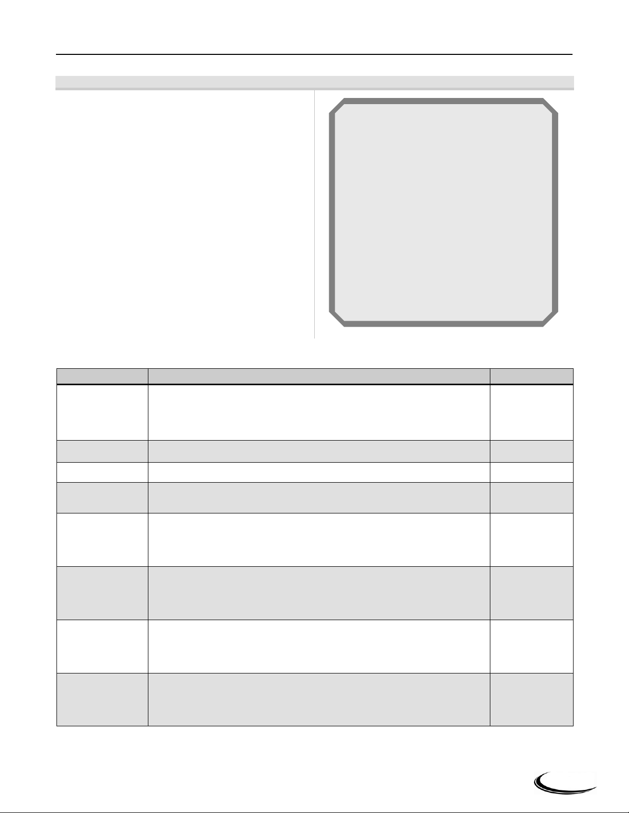
1.3 Home Screen
The Home Screen is displayed following initial power-up and can be displayed at anytime by simply pressing the
“Home” button. The Home Screen provides a summary of the current boiler status, most recent Alert or Lockout,
and readings from chosen boiler sensors. Figure 1-2 below, identifies each Home Screen and keypad item; Table
1-1 describes them.
Figure 1-2 Home Screen & Key Pad Identification
From the Home Screen the display offers easy access to diagnostic screens through the use of the horizontal
directional buttons (◄ ►) on the display keypad. Pressing either of the horizontal buttons advances you through
the Analog Sensor I/O (inputs/outputs), Digital I/O, and then back to the Home Screen.
Figure 1-3 Diagnostic Screens
Page 5
3
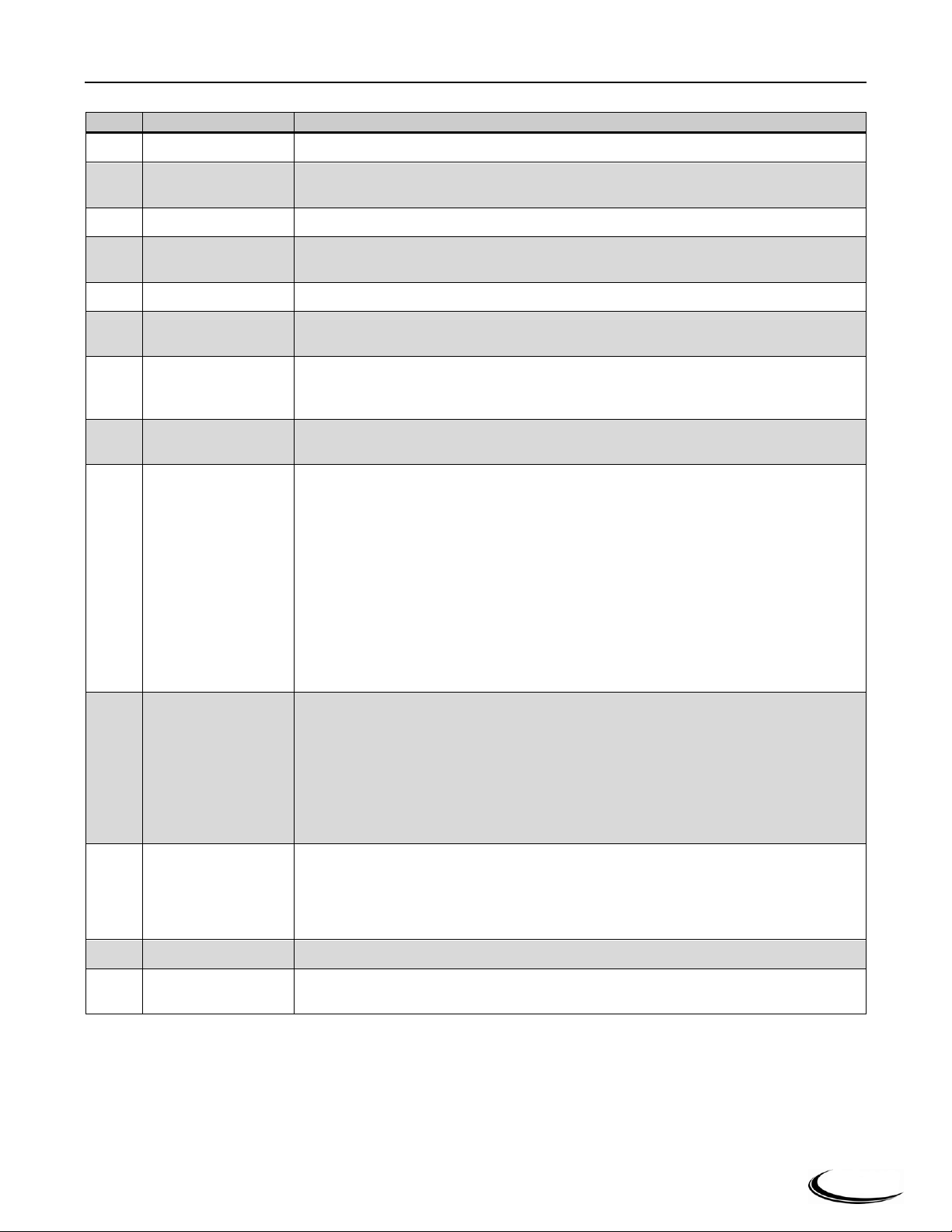
Item
Name
Description
1
Back button
Returns the display to the previous screen in the menu structure.
2
i-Information button
Displays the Main Menu screen, where all control settings, diagnostics, etc are accessed
via a series of sub-menus.
3
Home button
Returns the display to the Home Screen (screen illustrated in Figure 1-2).
4
Directional buttons
(horizontal)
Left and right buttons (◄ ►) allow navigation within some display screens. Also
provide access, via the Home Screen, to controller input and output diagnostic screens.
5
OK button
Used to select highlighted display items, necessary for confirming settings.
6
Direction buttons
(vertical)
Up and down buttons (▲ ▼) allow navigation within display screens.
7
Boiler summary
Provides the status of five (5) boiler readings (i.e. sensor inputs or boiler operating
conditions). From a list of 15 readings, the user can select which 5 will be displayed
/summarized on the Home Screen, see Section 2.6 Display Setup
8
Boiler name
Provides the name of the boiler, i.e. 110MBH; user can choose to change the name, see
Section 2.4.4.1 System ID & Access.
9
State
Indicates the current state of burner operation:
Initiate
Standby delay
Standby
Safe startup
Prepurge - Measured purge time
Prepurge - Drive to lightoff rate
Pre ignition test
Direct Burner ignition
Run
Postpurge
Lockout
10
Demand
Indicates the current heat demand source:
OFF (no heat demand)
CH (Central Heat demand – CH1)
LL [ Lead Lag heat demand – CH2 (LL)
DHW (Domestic Hot Water demand)
CH frost protection
DHW frost protection
LL frost protection
11
Access Status
Indicates the present level of access:
User (indicates that no password has been entered – adjustment of certain settings
will be blocked.
Installer (indicates that the installer password, “sola” has been entered, allowing
adjustment of all field adjustable parameters).
12
Lockout/alert/hold
Indicates the most recent Alert, or a current Hold or Lockout.
13
Clear
When selected, clears the most recent Alert from the Home Screen; also resets and clears
a current Lockout.
CHS Series Controller and Display │Slant Fin Corp.
Table 1-1 Home Screen & Key Pad Description (Reference Figure 1-2)
Page 6
4
i-Information – Main Menu screen, accessed
by pressing the “i” button, lists the major submenus. Use the arrow buttons to navigate the
menu options; when the desired option is
highlighted it will appear at the top of the
screen (i.e. Quick Start in the example right);
select by pressing the “OK” button.
Menu Item
Description
Reference
Quick Start
Provides a summary of the most common settings for installer adjustment.
Section 2.1
Login
Provides access to a keypad for entry of the installer password – many
parameters are installer level password protected.
Section 2.2
Test
Allows the installer to test specific firing rates and pump operation manually.
Section 2.3
Advanced Setup
Provides access to all parameter settings (including those in Quick Start), for
more advanced settings.
Section 2.4
Diagnostics
Lists the status of all controller inputs and outputs (i.e. sensors and switches);
also provides access to a history of Alerts and Lockouts.
Section 2.5
Display Setup
Allows the installer to set what information (i.e. sensor status) is displayed on the
Home Screen.
Section 2.6
Quick
Start
Test
Diagnostics
Login
Advanced
Setup
Display
Setup
Quick Start
Slant Fin Corp. │Controller and Display CHS Series
2.0 i-Information Screen (Main Menu)
Figure 2-1 i-Information Screen
Table 2-1 i-Information Screen Menu Options
Page 7
5
Quick Start – screen, accessed by selecting
“Quick Start” from the “i-Information” screen,
provides a summary of the most common settings
that will need to be adjusted (or considered) when
initially setting up the boiler. Use the up and down
(▲▼) buttons to navigate the menu options; when
the desired option is highlighted select by pressing
the “OK” button.
Each of the parameters under Quick Start are also
listed under separate setting groups under
“Advanced Setup”; where more advanced settings
can be accessed..
Parameter
Description
Factory Setting
CH setpoint
Setpoint value for CH modulation. If “Outdoor reset” is set to “Disable”, this is
the target temperature at the “Modulation sensor”. If “Outdoor reset” is set to
“Enable”, this is the maximum target temperature at the “Modulation sensor”
(Setpoint for CHI heat input).
180ºF
DHW setpoint
Boiler setpoint for DHW modulation. Range 60°F to 190°F
180ºF
Outdoor reset
Enables or disables CH outdoor reset function for CH1 heat inputs.
Enable
Low water temp
Minimum boiler setpoint; occurs when the outdoor temperature is equal to or
greater than the “Max outdoor temp”. Range 60°F to 140°F
95ºF
Max outdoor temp
Outdoor temperature that corresponds to the “Low water temp” setting.
Example: If the “Low water temp” setting is 95°F, and the “Max outdoor
temp” setting is 70°F, the boiler setpoint will be 95°F when the outdoor
temperature is 70°F or higher. Range 50°F to 95°F
70ºF
Min outdoor temp
Design Temperature - Outdoor temperature that corresponds to the “CH
setpoint” setting. Example: If the “CH setpoint” is 180°F, and the “Min
outdoor temp” setting is 0°F, the boiler setpoint will be 180°F when the
outdoor temperature is 0°F or lower. Range -40°F to 40°F
0ºF
Adjustable high
limit
Outlet water temperature high limit. Controller will not permit burner
operation above this setting. Recommend leaving configured as 200ºF. Range
100°F to 200°F
200ºF
Adjustable stack
limit
Stack exhaust gas high limit. Controller will lockout if exhaust gas
temperature exceeds this setting. Range 145°F to 220°F
220ºF
CH setpoint
DHW setpoint
Outdoor reset
Low water temp
Max outdoor temp
Min outdoor temp
Adjustable high limit
Adjustable stack limit
180 oF
180 oF
Enable
95
o
F
70
o
F
0
o
F
200
o
F
220
o
F
Quick Start
CHS Series Controller and Display │Slant Fin Corp.
2.1 Quick Start
Figure 2-2 Quick Start Screen
Table 2-2 Quick Start Configuration Parameters
Page 8
6
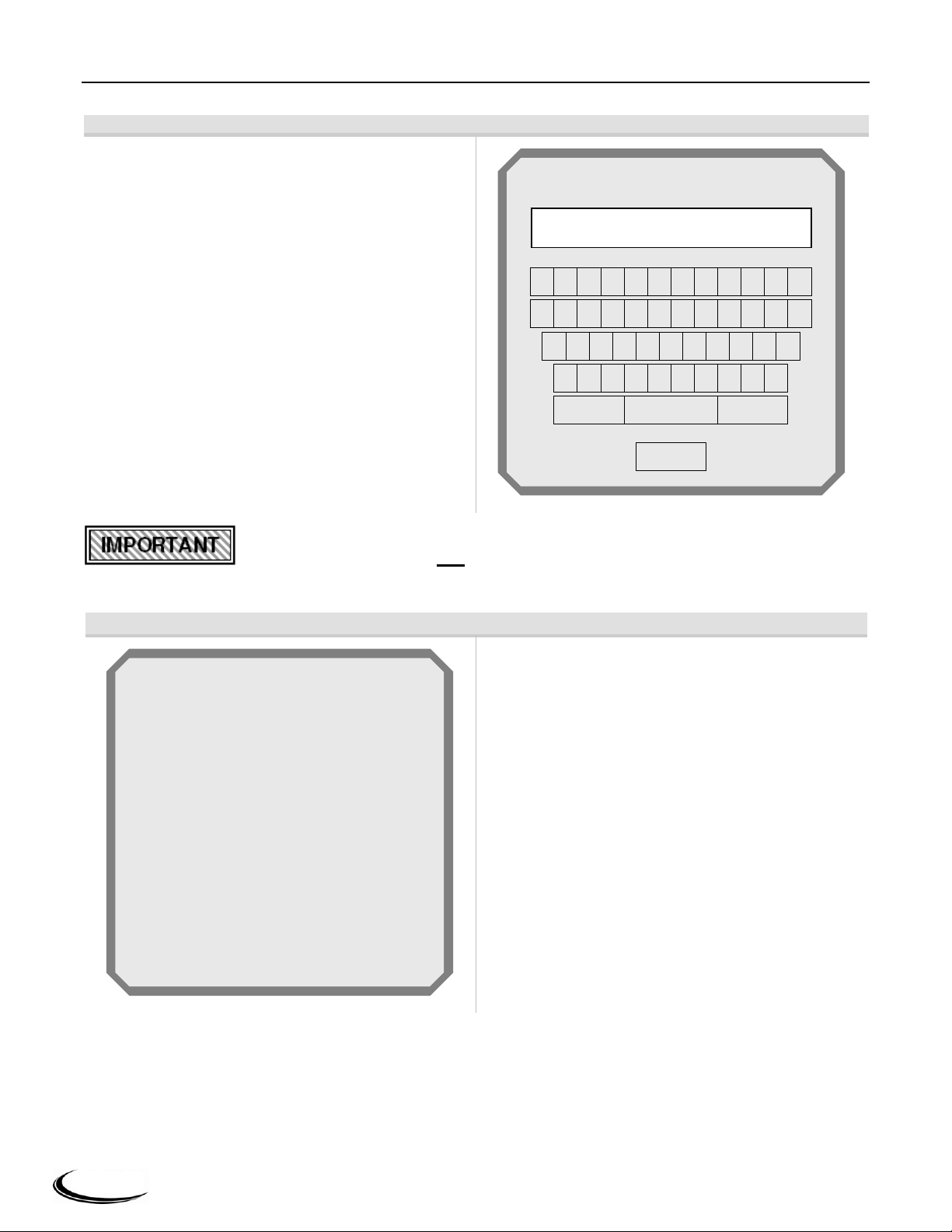
Login - Parameters that are password protected
require an installer to enter the password before they
can be changed. A message indicating this may
appear when a password protected parameter is
selected. To enter the password, touch the “iInformation” button and select Login to access the
keyboard screen.
Use the horizontal and vertical directional buttons
(▼▲◄►) on the keypad to navigate the keyboard
screen. Once the desired letter or number is
selected/highlighted, press the round “OK” button on
the keypad to confirm selection.
Once the password is filled in, select/highlight “OK”
on the keyboard, and press the round OK button on
the keypad to confirm selection.
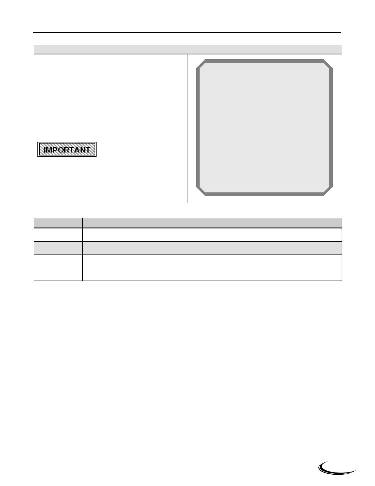
Figure 2-4 Test Screen Menu
Test – menu screen, accessed by selecting “Test”
from the “i-Information” screen, lists the three test
screen options. Use the up and down (▲▼) buttons
to navigate the menu options; when the desired option
is highlighted select by pressing the “OK” button.
1 2 3 4 5 6 7 8 9 0 -
=
q w e r t y u i o
p
[
]
a s d f g h j k l
;
'
z x c v b n m , .
/
Shift
BS
OK
Password
sola
Forced Rate
Manual Burner Operation
Manual Pump Operation
Test
Slant Fin Corp. │Controller and Display CHS Series
2.2 Login
Figure 2-3 Login Screen
Password - Many of the configuration parameters are password protected. The required
case-sensitive password is "sola" and must be entered in lower-case letters.
2.3 Test
Page 9
7
Figure 2-5 Forced Rate Test Screen
Forced Rate – test screen, permits the installer to
force the burner to operate at “high fire” or “low fire”
for the purpose of combustion setup and diagnoses.
Set the “Manual firing rate” to high or low fire by
using the up and down (▲▼) buttons to highlight
either “Set high fire” or “Set low fire”; then select it
by pressing the “OK” button.
When the test is complete, select “Stop test” to return
firing rate control to automatic.
The burner MUST be firing
to initiate “Start test”.
Parameter
Description
Set high fire *
When selected, sets “Manual firing rate” setting equal to the maximum modulation rate of the boiler.
Set low fire *
When selected, sets “Manual firing rate” setting equal to the minimum modulation rate of the boiler.
Start test *
When selected, initiates the forced rate test, burner will operate at the “Manual firing rate” setting
indicated on the screen. To stop test select “Stop test”; which will be displayed in place of “Start test”
once the test is initiated.
* = Password protected
State
Firing rate
Fan speed
Outlet temp
Manual firing rate
Test State: Idle
Test Timer: 0 sec
Set high fire
Set low fire
Start test
Standby
0 RPM
Low
71 oF
1625 RPM
Forced Rate
Burner must be in run state
CHS Series Controller and Display │Slant Fin Corp.
2.3.1 Forced Rate
Table 2-3 Forced Rate Parameters
Page 10
8
Figure 2-6 Manual Burner and Pump Operation Test Screens
Parameter
Description
Default
Burner
Switch *
Allows the installer to manually switch the burner off and on.
On
Manual
firing rate *
Establishes the burner firing rate (blower RPM) when “Firing rate control” is set to
“Manual in Run” or “Manual in Run & Standby”. Feature may be useful as a diagnostic
tool; i.e. to test burner operating characteristic at a specific firing rate.
N/A
Firing rate
control *
Establishes the firing rate control of the boiler:
Auto (firing rate – blower RPM is controlled by the boiler control)
Manual in Run (blower RPM is set to the “Manual firing rate” setting; only when
burner is running).
Manual in Run & Standby (blower RPM is set to the “Manual firing rate” setting).
Auto
* = Password protected
Burner switch
Manual firing rate
Firing rate control
Off
1625 RPM
Auto
Manual Burner Operation
CH Pump Control
DHW Pump Control
Boiler Pump Control
Auto
Auto
Auto
Manual Pump Operation
Slant Fin Corp. │Controller and Display CHS Series
2.3.2 Manual Burner and Pump Operation
Manual Burner Operation – test screen, allows the installer to manually control the firing rate of the burner.
Using the up and down (▲▼) buttons to highlight the menu options, and the “OK” button to select them, set
“Firing rate control” to “Manual”, then adjust “Manual firing rate” to the desired value.
Manual Pump Operation – test screen, allows the installer to manually turn the individual pumps on. Using the
up and down (▲▼) buttons to highlight the menu options, and the “OK” button to select them, set the desired
“Pump Control” to “On”.
Table 2-4 Manual Burner Operation Parameters
The burner MUST be firing to initiate Manual Burner Operation.
Setting “Burner switch” to “Off” will inhibit burner operation, regardless of the operating
conditions.
When the test is complete, return the settings to “Auto” to allow the control to
automatically turn the circulators off and on and modulate the burner firing rate as needed.
Page 11
9
Figure 2-7 Advanced Setup (Menu) Screen
Advanced Setup – menu screen, accessed by
selecting “Advanced Setup” from the “i-Information”
screen, lists all of the configuration parameter groups.
Use the up and down (▲▼) buttons to navigate the
menu options; when the desired option is highlighted
select by pressing the “OK” button.
Login – adjustment of many of the advanced settings
will prompt the user to login.
Name
Description
Reference:
CH Config
Edit Central Heat settings; CH1 heat input.
Section 2.4.1
DHW Config
Edit Domestic Hot Water settings.
Section 2.4.2
Lead Lag Config
Edit Lead-Lag Master and Slave settings; CH2 (LL) heat input.
Section 2.4.3
System Config
Edit temperature units, anti-short-cycle time, alarm silence time.
Section 2.4.4
Modulation Config
Edit burner modulation settings.
Section 2.4.5
Delta T Limits
Edit delay time for delta-t limit.
Section 2.4.6
T-rise Limits
Edit delay time for T-rise limit.
Section 2.4.6
Frost Protection Config
Enable/disable CH, DHW and LL frost protection
Section 2.4.7
Burner Timings & Rates
Read only, for information only.
Section 2.4.8
Burner Control Ignition
Read only, for information only.
Section 2.4.9
CH Config
DHW Config
Lead Lag Config
System Config
Modulation Config
Delta T Limits
T-rise Limits
Frost Protection Config
Burner Control Timings & Rates
Burner Control Ignition
Advanced Setup
CHS Series Controller and Display │Slant Fin Corp.
2.4 Advanced Setup
Table 2-5 Advanced Setup Menu Options
Page 12

10
Figure 2-8 Central Heat Configuration Main Menu Screen
CH Config – main menu screen, accessed by
selecting “CH Config” from the “Advanced Setup”
screen, lists the sub-menus specific to the Central Heat
Configuration. Use the up and down (▲▼) buttons to
navigate the menu options; when the desired option is
highlighted select by pressing the “OK” button.
The settings under “CH Config” are specific to boiler
operation given a local central heat demand, i.e. CH1
heat input.
Figure 2-9 Central Heat Configuration Sub-menu Screen
CH Config – sub-menu screen, allows the installer to
set parameters specific to the boiler response and
operation for local (i.e. non Lead Lag) Central Heat
demands. Use the up and down (▲▼) buttons to
navigate the menu options; when the desired option is
highlighted select by pressing the “OK” button.
Demand switch - Central heat demand can be
initiated by a contact closure to CH1, “LCI”, or by
boiler temperature, “Sensor only”.
Setpoint source – The boiler setpoint can be “Local”,
i.e. the “CH setpoint” set from the display, or “420mA” set from an external source.
Modulation sensor – With the “Setpoint source” set
to “Local”, the control can be set to use either the
“Outlet”, “Inlet” or “S10” (pipe) sensor for regulation
of burner modulation.
Mod rate source – The burner modulation can either
be controlled by the boiler control, “Local”, or by an
external source, “4-20mA”.
Demand switch
Setpoint source
CH setpoint
Off hystersis
On hysteresis
Modulation sensor
Mod rate source
CH Config
LCI
Local
180 oF
10 oF
20 oF
Outlet
Local
CH Config
Outdoor Reset Config
Warm weather shutdown
CH Config
Slant Fin Corp. │Controller and Display CHS Series
2.4.1 CH Config
2.4.1.1 CH Config – CH Config
Page 13

11
Parameter
Description
Factory Settings
Demand
switch *
Source of CH demand:
Sensor only (modulation sensor – no contact closure required)
LCI (contact closure of “CH1” to “R”, i.e. via a thermostat)
LCI
Setpoint
source *
Select the Central Heat setpoint source:
Local (control references “CH setpoint” setting)
4-20mA with sensor on/off [remote source]
Local
CH setpoint
Setpoint value for CH modulation. If “Outdoor reset” is set to “Disable”, this is the
target temperature at the “Modulation sensor”. If “Outdoor reset” is set to “Enable”,
this is the maximum target temperature at the “Modulation sensor” (see Section
2.4.1.2 Outdoor Reset Config). Range 60°F to 190°F
180°F
Off hysteresis
Value added to CH setpoint to determine water temperature at which the burner will
shut off e.g. if CH setpoint is 180°F, and CH off hysteresis is 10°F, the burner will be
shut off at 190°F. Range 2°F to 20°F
10°F
On hysteresis
Value subtracted from “CH setpoint” to determine water temperature at which the
burner will fire e.g. if “CH setpoint” is 180°F, and “CH on hysteresis” is 20°F, the
burner will fire at 160°F. Range 2 °F to 40°F
20°F
Modulation
sensor *
Select which sensor Central Heat will modulate to:
Outlet
Inlet
S10 [System (pipe) temperature sensor]
Outlet sensor
Mod rate
source *
Select which source controls the modulation rate:
Local [PID control]
4-20mA with sensor on/off [remote source]
Local
* = Password protected
CHS Series Controller and Display │Slant Fin Corp.
Use of 4-20mA Input
Setpoint source – If “Local” is selected as the “Setpoint source”, the “CH setpoint” value entered on the screen,
depicted in Figure 2-10, is used for control. If 4-20mA is selected as the “Setpoint source”, the boiler determines
its setpoint from the 4-20mA signal. The setpoint is calculated from a factory-set scale between 60°F
corresponding to 4mA, and 190°F corresponding to 20mA. If the 4-20mA input signal is invalid, out of range, or
absent, the “CH setpoint” is used until the signal is valid again. Regardless of the “Setpoint source”, “Local” or
“4-20mA”, the controller’s internal PID algorithm modulates the burner.
Mod rate source – The Slant/Fin CHS controller supports two methods of burner modulation for CH, selected
by the “Mod rate source” parameter, depicted on Figure 2-10; the factory set method is by internal PID
algorithm. The installer has the option to use a 4-20mA signal from an external control to directly modulate the
burner. Rates vary (see Section 2.4.5 Modulation Config) from minimum at 4mA to CH maximum at 20mA.
The 4-20mA signal does not create burner demand; a call for heat must be present; i.e. CHI input made when
“Demand Switch” = LCI..
Table 2-6 Central Heat Configuration Parameters
Page 14

12
Figure 2-10 Outdoor Reset Configuration Screen
(CH Config) Outdoor Reset Config – sub-menu
screen, allows the installer to set parameters specific
to the effect the outdoor temperature has on the
operation of the boiler during local (i.e. non Lead
Lag) Central Heat demands. Use the up and down
(▲▼) buttons to navigate the menu options; when
the desired option is highlighted select by pressing the
“OK” button.
Outdoor Reset is in effect only if the following two
conditions are met: “Outdoor reset” is set to "Enable",
and an outdoor temperature sensor is connected to the
boiler. The “Outdoor Reset Config” parameters,
together with the “CH Config” parameters, define the
relationship of boiler temperature setpoint to outdoor
temperature. Refer to Figure 2-12 for an example of
the relationship between outdoor temperature and
boiler temperature, with a given set of settings.
Parameter
Description
Factory Settings
Outdoor reset
enable
Enables or disables Outdoor reset
Enabled
Max outdoor
temp
Outdoor temperature that corresponds to the “Low water temp” setting. Example:
If the “Low water temp” setting is 95°F, and the “Max outdoor temp” setting is
70°F, the boiler setpoint will be 95°F when the outdoor temperature is 70°F or
higher. Range 50°F to 95°F
70ºF
Min outdoor
temp
Design Temperature - Outdoor temperature that corresponds to the “CH
setpoint” setting. Example: If the “CH setpoint” is 180°F, and the “Min outdoor
temp” setting is 0°F, the boiler setpoint will be 180°F when the outdoor
temperature is 0°F or lower. Range -40°F to 40°F
0ºF
Low water temp
Minimum boiler setpoint; occurs when the outdoor temperature is equal to or
greater than the “Max outdoor temp”. Range 60°F to 140°F
95ºF
Outdoor boost
max off point
Read only – functional in future revisions.
130ºF
Figure 2-11 Outdoor Reset Graph
Outdoor reset
Max outdoor temp
Min outdoor temp
Low water temp
Outdoor boost max off point
Enable
70 oF
0 oF
95 oF
130 oF
Outdoor Reset Config
Point defined by:
Min outdoor temp= 0ºF
Point defined by:
Max outdoor temp= 70ºF
Slant Fin Corp. │Controller and Display CHS Series
2.4.1.2 CH Config - Outdoor Reset Config
Table 2-7 Outdoor Reset Configuration Parameters
Page 15

13
Figure 2-12 WWSD Configuration Screen
(CH Config) Warm Weather Shutdown
(WWSD) – sub-menu screen, allows the installer to
enable the WWSD function for local (i.e. non Lead
Lag) Central Heat demands, and define at what
outdoor temperature it is initiated. Use the up and
down (▲▼) buttons to navigate the menu options;
when the desired option is highlighted select by
pressing the “OK” button.
When “Warm weather shutdown” is set to one of the
“Shutdown” options, and the outdoor temperature is
above the “Warm weather shdn setpoint”, CH
operation is inhibited.
CH operation is restored when the outdoor
temperature drops below the WWSD setpoint by a
fixed value of 4ºF.
Parameter
Description
Factory Settings
Warm weather
shutdown
Enable or Disable Warm Weather Shutdown and select shutdown options
Shutdown after demand ends
Shutdown immediately
Disable
Disable
Warm weather
shdn setpoint
Temperature at which local Central Heat operation is inhibited. Not applicable
when “Warm weather shutdown” is set to “Disable”. Range 50°F to120°F
60°F
Warm weather shutdown
Warm weather shdn setpoint
Disable
60 oF
Warm Weather Shutdown
CHS Series Controller and Display │Slant Fin Corp.
2.4.1.3 CH Config - Warm Weather Shutdown
Table 2-8 Warm Weather Shutdown Configuration Parameters
Page 16

14
Figure 2-13 Domestic Hot Water Configuration Screen
DHW Config – menu screen, accessed by selecting
“DHW Config” from the “Advanced Setup” screen, lists
the configuration parameters specific to boiler operation
for a DHW demand. Use the up and down (▲▼)
buttons to navigate the menu options; when the desired
option is highlighted select by pressing the “OK” button.
Demand switch - DHW demand can be initiated by a
contact closure, “DHW switch”, or by a tank
temperature sensor, “DHW Sensor with On/Off Temp”.
Mod sensor – The control can be set to use the “Outlet”
or “Inlet” sensor for regulation of burner modulation.
When “Demand switch” is set to
“DHW Sensor with On/Off
Temp”, demand is determined by
the Demand ON and OFF temp settings.
Parameter
Description
Factory Settings
Demand
switch *†
Select which sensor is the DHW demand source:
DHW switch
DHW Sensor with On/Off Temp
(If “DHW Sensor with On/Off Temp is selected, a tank sensor must be used to
generate a demand.)
DHW switch
Mod
sensor *
Select the DHW modulation sensor:
Outlet
Inlet
Outlet
DHW
setpoint
Setpoint for DHW modulation. If “Mod sensor” is set to “DHW” or “Inlet”, reduce
setting accordingly. Range 60°F to 190°F
180°F
Off
hysteresis *
Value added to “DHW setpoint” to determine water temperature at which the burner
will shut off e.g. if “DHW setpoint” is 180°F, and “Off hysteresis” is 10°F, the
burner will be shut off at 190°F. Range 5°F to 70°F
10°F
On
hysteresis *
Value subtracted from “DHW setpoint” to determine water temperature at which the
burner will fire e.g. if “DHW setpoint” is 180°F, and “On hysteresis” is 10°F, burner
ignition occurs at 170°F. Range 2°F to 40°F
10°F
Priority
time *
Time period during which a DHW demand has priority. If override time has elapsed,
the boiler and CH pump (Pump C) will service a CH demand regardless of DHW
demand. Value=0 inhibits DHW priority. Range 0 to 18 hours.
2 hour
Demand
ON temp *
DHW demand is switched ON when DHW tank temperature is < this setting.
Applied when “Demand switch” is set to “DHW Sensor with on/off temperatures”.
Range 60°F to 165°F.
135 oF
Demand
OFF temp *
DHW demand is switched OFF when DHW tank temperature is ≥ this setting.
Applied when “Demand switch” is set to “DHW Sensor with on/off temperatures”.
Range 65°F to 170°F.
140 oF
* = Password protected
† = If “Demand switch” is set to “DHW Sensor with On/Off Temp”, demand is determined by the Demand ON and OFF temp settings.
DHW tank sensor MUST be used in conjunction with a DHW temperature safety shutoff
switch. Failure to provide such a switch may result in property damage, serious injury to
occupants, or possibly death.
Demand switch
Mod sensor
DHW setpoint
Off hystersis
On hysteresis
Demand ON temp
Demand OFF temp
DHW switch
Outlet
180 oF
10 oF
10 oF
135 oF
140 oF
DHW Config
Slant Fin Corp. │Controller and Display CHS Series
2.4.2 DHW Config
Table 2-9 DHW-Domestic Hot Water Configuration Parameters
Page 17

15
CHS Series Controller and Display │Slant Fin Corp.
2.4.3 Lead Lag Config
The CHS boiler can be used as a stand-alone unit or as part of a cascaded arrangement with as many as 8 CHS
boilers. The Lead Lag Configuration parameters determine the boiler’s (or group of boilers) behavior during a
Lead Lag heat demand [i.e. CH2 (LL) heat input]. Only a demand on CH2 (LL) will initiate Lead-Lag, or
“staging”, of cascaded boilers. For stand-alone boilers, the CH2 (LL) demand simply behaves as a second heat
input (CH1 being the first). Note: a demand for central heat from CH1, takes priority over a demand for central
heat from CH2 (LL).
To enable, or allow the use of Lead-Lag function and the CH2 (LL) input, the “Lead Lag Master Config”
parameter “Master enable”, must be set to “Enable”; see Section 2.4.3.1 Lead Lag Master Config. In Lead Lag
cascade boiler arrangements, only one boiler has “Master enable” set to “Enable”, the others are set to “Disable”
(factory default).
Check List for Lead Lag Installation:
1. All Boilers in Cascade
a. Wire boilers together – Daisy-chain Data Communication wiring between boilers. See Installation and
Operating Instructions (Not applicable for stand-alone boiler applications).
b. Lead Lag Slave Configuration Settings (Optional) – Adjust the “Lead Lag Slave Config” setting “Slave
mode”, as desired. See Section 2.4.3.2.
c. MB2 Modbus address – set a unique “MB2 Modbus address” for each boiler. See Section 2.4.4.1 System
ID & Access.
2. Master Boiler in Cascade
a. Set “Master enable” to “Enable” – Select one boiler in the cascade to be Master; set its “Master enable”
setting to “Enable”. Other boilers are left as “Disable” (factory default). For stand-alone boilers the lone
boiler must have “Master enable” configured as “Enable”. See Section 2.4.3.1 Lead Lag Master Config.
b. Lead Lag Master Configuration Settings – Adjusted the “Lead Lag Master Config” and “Outdoor Reset”
settings to the desired values on the boiler with “Master enable” configured as “Enable”. No need to
adjust these settings on other boilers.
c. Heat Demand Input [CH2 (LL)] – Wire the head demand input to CH2 (LL) of the boiler with “Master
enable” configured as “Enable”.
d. System Sensor (Optional) – Wire the system (pipe) sensor to the boiler with “Master enable” configured
as “Enable”.
3. Any Boiler in Cascade
a. Outdoor Sensor (Optional) – Wire the outdoor sensor to any boiler within the cascade. Note: only one
outdoor sensor is required for a multiple boiler application.
b. System Pump Control (Optional) – With “CH pump use for LL master” set to “On”. The respective boiler
will operate the CH pump (Pump C) anytime there is a Lead Lag heat demand. See Section 2.4.4.2 Pump
Config.
Page 18

16
Figure 2-14 Lead Lag Configuration Main Menu Screen
Lead Lag Config – main menu screen, accessed by
selecting “Lead Lag Config” from the “Advanced
Setup” screen, lists the sub-menus specific to the Lead
Lag Configuration. Use the up and down (▲▼)
buttons to navigate the menu options; when the
desired option is highlighted select by pressing the
“OK” button.
Figure 2-15 LL Master Configuration Screen
Lead Lag Master Config – sub-menu screen,
allows the installer to set parameters specific to the
boiler response and operation for Lead Lag CH2 (LL)
demands. Use the up and down (▲▼) buttons to
navigate the menu options; when the desired option is
highlighted select by pressing the “OK” button.
Master enable – must be set to “enable” in order for
the boiler to respond to a CH2 (LL) demand (only one
boiler in the cascade can have “Master enable” set to
“Enable”.
Setpoint source – The boiler LL setpoint can be
“Local”, i.e. the “Setpoint” set from the display, or “420mA” set from an external source.
System Sensor – When using the optional system
(pipe) sensor; the controller automatically uses it as
the modulation sensor – reduce the “Setpoint”
accordingly.
Master enable
Setpoint source
Setpoint
Off hysteresis
On hysteresis
P gain
I gain
Base load common rate
Disable
Local
150 oF
15 oF
15 oF
30
15
70%
Lead Lag Master Config
Lead Lag Master Config
Lead Lag Slave Config
Lead Lag Outdoor Reset
Lead Lag Config
Slant Fin Corp. │Controller and Display CHS Series
2.4.3.1 Lead Lag Master Config
Page 19

17
Parameter
Description
Factory Settings
Master
enable *
Enable or Disable Lead Lag Master. One (and only one) unit must be set to
“Enable” for Lead Lag operation to function.
Disable
Setpoint
source *
Select the Lead Lag setpoint source:
Local (control references “Setpoint” setting)
4-20mA (control references 4-20mA signal from an external control). “Outdoor
reset enable” must be set to “Disable” when using a 4-20mA signal; see Section
2.4.3.3 Lead Lag Outdoor Reset.
Local
Setpoint
Setpoint value for Lead Lag modulation. Range 60°F to 190°F.
150°F
Off
Hysteresis *
Value added to the “Setpoint” to determine water temperature at which the burner
will shut off. Example: If “Setpoint” is 150°F, and “Off hysteresis” is 15°F, the
burner will be shut off at 165°F. Range 5 °F to 70°F.
15°F
On
Hysteresis *
Value subtracted from “Setpoint” to determine water temperature at which the
burner will fire. Example: If “Setpoint” is 150°F, and “On hysteresis” is 10°F,
burner ignition occurs at 140°F. Range 2°F to 40°F.
10°F
P Gain *
Gain applied to the proportional term of the LL PID control algorithm. Range 5 to
50 (no units). Decrease to slow rate of control response.
30
I Gain *
Gain applied to the integral term of the LL PID control algorithm. Range 5 to 50 (no
units). Decrease to slow rate of control response.
15
Base load
common *
Maximum modulation rate of all firing units when other units are still available and
idle. Range 25 - 100%.
70%
* Password protected
CHS Series Controller and Display │Slant Fin Corp.
Table 2-10 Lead Lag Master Configuration Parameters
Use of 4-20mA Input
Setpoint source – If “Local” is selected as the “Setpoint source”, the “Setpoint” value entered on the screen,
depicted in Figure 2-16, is used for control. If 4-20mA is selected as the “Setpoint source”, the boiler
determines its setpoint from the 4-20mA signal. The setpoint is calculated from a factory-set scale between 60°F
corresponding to 4mA, and 190°F corresponding to 20mA. If the 4-20mA input signal is invalid, out of range, or
absent, the “Setpoint” is used until the signal is valid again. Regardless of the “Setpoint source”, “Local” or “4-
20mA”, the controller’s internal PID algorithm modulates the burner. The 4-20mA signal does not create
burner demand; a call for heat must be present at the CH2 (LL) input.
Page 20

18
Figure 2-16 LL Slave Configuration Screen
Lead Lag Slave Config – sub-menu screen, allows
the installer to set the “Slave mode” which establishes
the order in which the boiler is chosen during the
staging sequence of a Lead Lag demand.
Use First – This mode has priority over all others. A
unit with its “Slave mode” set to "Use First", will
always fire first before any other slave in the cascade
and it will be the last one dropped.
Equal run time – This mode stages the units based
on run time equalization where the unit with the least
burner hours fires first and the most burner hours
fires last. Only "Use First" has higher priority.
Use Last – This mode has the lowest priority. A unit
with its “Slave mode” set to "Use Last", will always
fire last after every other slave in the cascade is
running. It will be the last slave to fire and the first
one dropped.
Parameter
Description
Factory Settings
Slave mode *
Select slave mode from drop down list:
Use First
Equal run time
Use Last
Equal run time
* Password protected
Slave mode
Equal run time
Lead Lag Slave Config
Slant Fin Corp. │Controller and Display CHS Series
2.4.3.2 Lead Lag Slave Config
Table 2-11 Lead Lag Slave Configuration Parameters
Page 21

19
Figure 2-17 LL Outdoor Reset Screen
(LL Config) Outdoor Reset Config – sub-menu
screen, allows the installer to set parameters specific
to the effect the outdoor temperature has on the
operation of the boiler during a CH2 (LL) demand.
Use the up and down (▲▼) buttons to navigate the
menu options; when the desired option is highlighted
select by pressing the “OK” button.
Outdoor Reset is in effect only if the following two
conditions are met: “Outdoor reset enable” is set to
"Enable", and an outdoor temperature sensor is
connected to the boiler. The “Lead Lag Outdoor
Reset” parameters, together with the “Lead Lag
Master Config” parameters, define the relationship of
boiler temperature setpoint to outdoor temperature.
Refer to Figure 2-12 for an example of the
relationship between outdoor temperature and boiler
temperature, with a given set of settings.
Parameter
Description
Factory Settings
Outdoor reset
enable *
Enables or disables Outdoor reset
Enabled
Max outdoor
temp *
Outdoor temperature that corresponds to the “Low water temp” setting. Example:
If the “Low water temp” setting is 85°F, and the “Max outdoor temp” setting is
70°F, the boiler setpoint will be 85°F when the outdoor temperature is 70°F or
higher. Range 50°F to 95°F
70ºF
Min outdoor
temp *
Design Temperature - Outdoor temperature that corresponds to the “Setpoint”
setting. Example: If the “Setpoint” is 150°F, and the “Min outdoor temp” setting
is 0°F, the boiler setpoint will be 150°F when the outdoor temperature is 0°F or
lower. Range -40°F to 40°F
0ºF
Low water
temp *
Minimum boiler setpoint; occurs when the outdoor temperature is equal to or
greater than the “Max outdoor temp”. Range 60°F to 140°F
85ºF
Outdoor boost
max off point *
Read only – functional in a future revision.
130ºF
* = Password protected
Outdoor reset enable
Max outdoor temp
Min outdoor temp
Low water temp
Outdoor boost max off point
Enable
70 oF
0 oF
85 oF
130 oF
Lead Lag Outdoor Reset
CHS Series Controller and Display │Slant Fin Corp.
2.4.3.3 Lead Lag Outdoor Reset
Table 2-12 Lead Lag Outdoor Reset Config Parameters
Page 22

20
Figure 2-18 System Configuration Main Menu Screen
System Config – main menu screen, accessed by
selecting “System Config” from the “Advanced
Setup” screen, lists the sub-menus specific to the
System Configuration. Use the up and down (▲▼)
buttons to navigate the menu options; when the
desired option is highlighted select by pressing the
“OK” button.
Figure 2-19 System Identification & Access Screen
System ID & Access – sub-menu screen contains
information about the CHS controller; it also provides
the installer with the ability to change the “Boiler
name” as it appears on the display, and the “Modbus
address”, which is necessary for configurating Lead
Lag multiple boiler installations. Use the up and
down (▲▼) buttons to navigate the menu options;
when the desired option is highlighted select by
pressing the “OK” button.
MB2 Modbus address – each boiler in a Lead Lag
multiple boiler installation, must have a unique MB2
Modbus address.
Boiler name
OEM ID
MB1 Modbus address
MB2 Modbus address
Modbus address
Modbus port used
Product ID
Product family
OS number
Model name
Software version
Date code
Application revision
Safety revision
110MBH
F/T110v06-18-12
1
1
1
MB1
IResidential
Hydronic boiler
R7910B1015
R7910B1015s1m
4104.2901
1117
19
13
System ID & Access
System ID & Access
Pump Config
Statistics Config
High Limits
System Config
System Config
Slant Fin Corp. │Controller and Display CHS Series
2.4.4 System Config
2.4.4.1 System ID & Access
Page 23

21
Parameter
Description
Factory Settings
Boiler name *
Name describing the specific boiler. Limited to 20 characters.
e.g.: 110MBH
OEM ID
Name identifying factory configuration settings; field is read only.
N/A
MB1 Modbus
address *
Modbus communication address used by the display to identify the attached
controller. No need to change this setting. Range: 1 – 8.
1
MB2 Modbus
address *
Unique controller I.D. needed when multiple boilers are connected together in a
Lead Lag cascade configuration. Each boiler in a Lead Lag cascade
configuration must have a unique setting. Range: 1 – 8.
1
Modbus address
Displays the “MB1 Modbus address” setting – do not adjust this setting.
1
Modbus port used
Identifies the Modbus port used by the display to controller; field is read only.
MB1
Product ID
Controller type identification; field is read only.
Residential
Product family
Hydronic boiler
OS number
Controller model identification; field is read only.
R7910B1015
Model name
Software version
Controller software version identification; field is read only.
N/A
Date code
Controller date code; field is read only.
N/A
Application
revision
Controller application revision; field is read only.
N/A
Safety
revision
Controller safety revision; field is read only.
N/A
CHS Series Controller and Display │Slant Fin Corp.
Table 2-13 System Identification & Access Parameters
* = Password protected
Page 24

22
Figure 2-20 Pump Configuration
Pump Config – sub-menu screen allows adjustment
of the individual pump overrun times; also allows the
individual pumps to be manually turned on for testing
purposes. Use the up and down (▲▼) buttons to
navigate the menu options; when the desired option is
highlighted select by pressing the “OK” button.
CH pump use for LL Master – for Lead Lag
multiple boiler configurations; set this parameter to
“On” on the boiler that is controlling the System
pump with the Pump C output.
pump control – This may be
used to manually override
automatic control of the pumps for testing purposes.
If used in this manner, ensure that it is set back to
“Auto”; otherwise, the selected pump(s) will remain
powered on indefinitely.
Parameter
Description
Factory Settings
CH pump
control *
Switches CH pump (Pump C) control from Automatic to ON.
Auto
CH overrun
time *
Amount of time the CH pump (Pump C) will continue to run after a CH [CH1
or CH2 (LL)] demand ends. Range 0 to 1080 minutes.
0 sec
CH pump use for
LL master *
Check box used to allocate Pump C output as the system pump operator for
Lead Lag applications.
off
Boiler pump
control *
Switches Boiler pump (Pump B) control from Automatic to ON.
Auto
Boiler pump
overrun time *
Amount of time the Boiler pump (Pump B) will continue to run after burner
shutdown. Range 0 to 1080 minutes.
30 sec
DHW pump
control *
Switches DHW pump (Pump A) control from Automatic to ON.
Auto
DHW pump
overrun time *
Amount of time the DHW pump (Pump A) will continue to run after a DHW
demand ends. Range 0 to 1080 minutes.
10 sec
* = Password protected
CH pump control
CH pump overrun time
CH pump use for LL Master
Boiler pump control
Boiler pump overrun time
DHW pump control
DHW pump overrun time
Auto
0 sec
off
Auto
30 sec
Auto
10 sec
Pump Config
Slant Fin Corp. │Controller and Display CHS Series
2.4.4.2 Pump Config
Table 2-14 Pump Configuration Parameters
Page 25

23
Figure 2-21 Statistics Configuration Screen
Statistics Config – sub-menu screen displays the
number of burner and pump cycles, as well as burner
run time. Use the up and down (▲▼) buttons to
navigate the menu options; when the desired option is
highlighted select by pressing the “OK” button.
Pump cycle counts can be reset by the installer, for
example when a circulator is replaced.
Burner cycles and Burner run
time counters cannot be reset.
Parameter
Description
Factory Settings
Burner cycle
count
Number of burner cycles on controller. Not resettable by the installer. Range 0 to
999,999.
0
Burner run time
Total number of hours of burner operation. Range 0 to 999,999 hours.
0 hour
Boiler pump
cycle count *
Number of Boiler pump (Pump B) cycles since last reset. Range 0 to 999,999.
0
CH pump cycle
count *
Number of CH pump (Pump C) cycles since last reset. Range 0 to 999,999.
0
DHW pump
cycle count *
Number of DHW pump (Pump A) cycles since last reset. Range 0 to 999,999.
0
Burner cycle count
Burner run time
Boiler pump cycle count
CH pump cycle count
DHW pump cycle count
29
7 hour
75
56
74
Statistics Config
CHS Series Controller and Display │Slant Fin Corp.
2.4.4.3 Statistics Config
Table 2-15 Statistics Configuration Parameters
* = Password protected
Page 26

24
Figure 2-22 High Limit Screen
Parameter
Description
Factory
Outlet high limit
response
Indicates controller response to an outlet temperature exceeding the “Outlet high
limit setpoint”. Parameter is read only.
Recycle & Hold
Outlet high limit response
Recycle & hold
High Limit
Slant Fin Corp. │Controller and Display CHS Series
2.4.4.4 High Limit
High Limit – sub-menu screen displays the outlet limit response. This value is “read only” and cannot be
adjusted.
Table 2-16 High & Stack Limit Parameters
Page 27

25
Figure 2-23 System Configuration Screen
System Config – sub-menu screen allows the
operator to set the temperature units (ºF/ºC) and the
burner “Anti short-cycle time”. Use the up and down
(▲▼) buttons to navigate the menu options; when
the desired option is highlighted select by pressing the
“OK” button.
Anti short-cycle time - This
feature does not apply to
Domestic Hot Water demand or recycle events.
The Anti short-cycle feature is designed to prevent
excessive burner on/off cycling due to short or rapid
thermostat cycles, low heating load, etc.
Parameter
Description
Factory Settings
Temperature
units
Select which temperature units to display:
Fahrenheit
Celsius
Fahrenheit
Anti shortcycle time *
Whenever the burner is turned off due to no demand the anti-short-cycle timer is
started and the burner remains in a Standby Delay condition waiting for this time to
expire.
Range 0 to 60 minutes (1 hour).
5 min
Burner off
inhibit time *
If demand changes from a high-temperature setpoint to a lower setpoint (e.g. from
DHW to CH), water temperature may exceed the burner off point for the new
demand. This value determines how long the control will ignore the burner off
hysteresis or threshold before shutting down the burner, in order to reduce burner
cycling. Range 0 to 30 minutes.
10 sec
General
Config
Allows for advanced parameter configuration modifications – only use when
instructed by Slant/Fin technical support.
N/A
* Password protected
Temperature units
Anti short-cycle time
Burner off inhibit time
General Config
Fahrenheit
5 min
10 sec
System Config
CHS Series Controller and Display │Slant Fin Corp.
2.4.4.5 System Config
Table 2-17 System Configuration Parameters
Page 28

26
Figure 2-24 Modulation Configuration Screen
Modulation Config – menu screen, accessed by
selecting “Modulation Config” from the “Advanced
Setup” screen, allows for adjustment of the min. and
max. modulation rates of the boiler. Use the up and
down (▲▼) buttons to navigate the menu options;
when the desired option is highlighted select by
pressing the “OK” button.
Modulation rates are listed by model number:
CH and DWH
Max Modulation Rate
Min Modulation
Rate
CHS-85 = 6300
CHS-110 = 7000
CHS-155 = 3700
CHS-175 = 4100
CHS-200 = 4650
CHS-250 = 5900
CHS-300 = 5000 (4800 on LP)
CHS-399 = 6900 (6600 on LP)
85 = 1525
110 = 1625
155 = 900
175 = 900
200 = 900
250 = 900
300 = 1500
399 = 1500
Parameter
Description
Factory Settings
CH max
modulation rate *
Maximum permissible blower speed during CH demand [CH1 or CH2 (LL)].
Range is model dependent.
Model dependent
DHW max
modulation rate *
Maximum permissible blower speed during DHW demand. Range is model
dependent.
Model dependent
Min modulation
rate *
Minimum permissible blower speed. Range is model dependent.
Model dependent
* = Password protected
CH max modulation rate
DHW max modulation rate
Min modulation rate
7000 RPM
7000 RPM
1625 RPM
Modulation Config
Slant Fin Corp. │Controller and Display CHS Series
2.4.5 Modulation Config
Table 2-18 Modulation Configuration Parameters
Page 29

27
Figure 2-25 Delta T & T-rise Limits Screens
Parameter
Description
Factory Settings
Delta T
delay *
Delay time between burner cycles when Delta T limit is exceeded. Range 1 to 60
minutes.
5 min
Outlet T-rise
delay *
Delay time between burner cycles when T-rise limit is exceeded. Range 1 to 60
minutes.
5 min
*=Password Protected
Outlet T-rise delay
5 min
T-rise Limits
Delta T delay
5 min
Delta T Limits
CHS Series Controller and Display │Slant Fin Corp.
2.4.6 Delta T & T-rise Limits
Delta T Limits – accessed by selecting “Delta T Limits” from the “Advanced Setup” screen; Delta T is the
difference in water temperature between Inlet and Outlet of the boiler. If the temperature difference (Delta T) is
greater than 60oF the burner is shut off for the time specified before firing again. An initial cycle and two recycles
are allowed before Lockout occurs.
T-rise Limits – accessed by selecting “T-rise Limits” from the “Advanced Setup” screen; T-rise is the rate of
increase of the boiler Outlet temperature. If the boiler outlet temperature increases by a rate greater than
4oF/second the burner will recycle with a delay equal to the “Outlet T-rise delay” setting. An initial cycle and two
recycles are allowed before Lockout occurs.
Table 2-19 Delta T & T-rise Limits Parameters
Page 30

28
Figure 2-26 Frost Protection Screen
Frost Protection Config – accessed by selecting
“Frost Protection Config” from the “Advanced
Setup” screen. Provides optional freeze protection
for the boiler system. Use the up and down (▲▼)
buttons to navigate the menu options; when the
desired option is highlighted select by pressing the
“OK” button.
When set to “Enable”, causes the respective
circulators to operate when the inlet temperature
drops below 45°F; and the burner to fire (at the min.
modulation rate) when the outlet temperature drops
below 38°F.
Parameter
Description
Factory Settings
CH frost
protection *
Enable or Disable frost protection for central heat (i.e. Pumps B and C).
Enabled
DHW frost
protection *
Enable or Disable frost protection for DHW (i.e. Pumps A and B).
Disabled
Lead Lag frost
protection *
Enable or Disable frost protection for lead lag (i.e. Pumps B and C). Each slave
detects frost protection and notifies the Master.
Disabled
* Password protected
CH frost protection
DHW frost protection
Lead Lag frost protection
Enable
Disable
Disable
Frost Protection Config
Slant Fin Corp. │Controller and Display CHS Series
2.4.7 Frost Protection Config
Table 2-20 Frost Protection Configuration Parameters
Page 31

29
Figure 2-27 Burner Control Ignition and Timings & Rates Screens
Parameter
Description
Factory Settings
Postpurge rate *
Rate the blower will operate following the shutdown of the burner. Parameter
is read only.
4500 RPM
Postpurge time *
Time the blower will operate following the shutdown of the burner.
Parameter is read only.
25 sec
Adjustable
lightoff rate *
Rate the blower will operate during burner ignition. Range 2500 rpm to 5000
rpm.
4000 RPM
Postpurge rate
Postpurge time
4500 RPM
20 sec
Burner Timings & Rates
Adjustable lightoff rate
4000 RPM
Burner Control Ignition
CHS Series Controller and Display │Slant Fin Corp.
2.4.8 Burner Control Ignition and Timings & Rates
Burner Timings & Rates – accessed by selecting “Burner Timings & Rates” from the “Advanced Setup” screen.
Displays the Postpurge rate and time settings; values are “read only” and cannot be adjusted.
Burner Control Ignition – accessed by selecting “Burner Control Ignition” from the “Advanced Setup” screen.
Displays the “Adjustable lightoff rate” setting.
Table 2-21 Burner Control Ignition and Timings & Rate Parameters
* Password protected
Page 32

30
Figure 2-28 Diagnostic Input/Output Screens
Diagnostics – menu screen, accessed by selecting
“Diagnostics” from the “i-Information” screen, allows
the user to view the operational status of the boiler.
Use the up and down (▲▼) buttons to navigate the
menu options; when the desired option is highlighted
select by pressing the “OK” button.
Analog Sensors – indicates the status of all
temperature sensors, flame sensor, blower speed (both
demanded and actual), and optional 4-20mA input
signal; see Figure 2-31.
Digital IO – indicates the status of each on/off input
and output, i.e. pump outputs and thermostat inputs;
see Figure 2-31.
Analog Sensors
Digital IO
Analog Sensors
Digital IO
History
Diagnostics
Outlet temp
Inlet temp
Delta T
DHW temp
Stack temp
Outdoor temp
Fan speed
Flame signal
Firing rate
4-20mA input
System sensor
70 oF
70 oF
1 oF
OPEN
71 oF
OPEN
LOW
0.00 A
0 RPM
OPEN
Outlet
Boiler pump (B)
CH pump (C)
DHW pump (A)
Blower/HSI
Eternal ignition
Pilot valve
Main valve
Alarm
Interlock (ILK)
Pre-ignit interlock (PTI)
Load control input (LCI)
STAT (Demand)
Time Of Day
Safety relay
off
off
off
off
off
off
off
off
on
off
off
off
off
off
Slant Fin Corp. │Controller and Display CHS Series
2.5 Diagnostics
Figure 2-29 Diagnostic Screens
Page 33

31
Figure 2-30 History Screen
History – sub-menu screen provides access to a log
of past Lockouts and Alerts. Use the up and down
(▲▼) buttons to navigate the menu options; when
the desired option is highlighted select by pressing
the “OK” button.
Figure 2-31 Example Lockout History Record Screen
Lockout/Alert Record – by selecting a Lockout or
Alert event from the list of Lockouts/Alerts, the
display provides specific information about the
operating condition of the boiler during the
Lockout/Alert (see example left). This information
can be helpful for troubleshooting.
Lockout History
Alert Log
History
Lockout 67
ILK OFF
Cycle: 8 Hours: 3
Time: 0 sec
State: Run
First out: None
Outlet: 77ºF
Inlet: 76ºF
DHW: 110ºF
Lockout History Record 1
CHS Series Controller and Display │Slant Fin Corp.
2.5.1 History
The CHS controller identifies and records two kinds of events and categorizes them as either Lockouts or Alerts.
The bulleted lists below indicate the significance of each type of fault:
Lockouts:
Cause the burner to shutdown and require manual intervention to reset the controller from Lockout
Always cause the Alarm contacts to close
Are logged in the Lockout History
Alerts:
Events reported by the controller
For informational purposes only
Page 34

32
Figure 2-32 Display Setup User Customizable Screen
Display Setup – menu screen, accessed by selecting
“Display Setup” from the “i-Information” screen,
allows the user to select which value (operating
parameter or sensor reading) is displayed on each of
the first 5 lines of the Home Screen. Use the up and
down (▲▼) buttons to navigate the menu options;
when the desired option is highlighted select by
pressing the “OK” button.
The comprehensive list of sensor I/O is identified in
Table 2-22 below.
Value
Description
System setpoint
Indicates the actual local CH setpoint (i.e. for a CH1 demand); adjusts for outdoor reset.
Operating temp
Indicates the temperature at the sensor used for burner modulation during a local CH or DHW
demand, i.e. boiler inlet, boiler outlet or system/pipe sensor.
Outlet temp
Indicates the temperature reading from the boiler outlet sensor.
Inlet temp
Indicates the temperature reading from the boiler inlet sensor.
Outdoor temp
Indicates the temperature reading from the outdoor sensor.
Delta T
Indicates the temperature difference between the boiler inlet and outlet sensors.
LL Operating temp
Indicates the temperature at the sensor used for burner modulation during a Lead Lag demand, i.e.
boiler outlet or system/pipe sensor.
LL System setpoint
Indicates the actual Lead Lag setpoint [i.e. for a CH2 (LL) demand]; adjusts for outdoor reset.
Fan speed
Indicates the speed that the combustion blower is running at – tachometer reading.
Flame signal
Indicates the flame current sensed from the flame probe.
Firing rate
Indicates the speed that the combustion blower is being commanded to operate at.
DHW temp
Indicates the dhw tank temperature (if used) or OPEN/CLOSED for Aquastat switch status.
Stack temp
Indicates the temperature reading from the boiler stack sensor.
4-20mA input
Indicates the input signal from an external 4-20mA source (used for direct burner modulation or
establishing temperature setpoint).
Lead Lag temp
Indicates the temperature reading from an optional system/pipe sensor.
LCD contrast 270
Home screen l ine 1: System setpo 180oF
Home screen l ine 2: Operating tem 71oF
Home screen l ine 3: Outlet temp 71oF
Home screen l ine 4: Inlet temp 71oF
Home screen l ine 5: Outdoor temp OPEN
OS number DSP49G2094
Software version 0.14
Display Setup
Slant Fin Corp. │Controller and Display CHS Series
2.6 Display Setup
Table 2-22 List of Optional Values for Display on Home/Summary Screen
Page 35

33
CHS Series Controller and Display │Slant Fin Corp.
NOTES
Page 36

©Slant/Fin Corp. 2013
SLANT/FIN CORPORATION, Greenvale, N.Y. 11548 • Phone: (516) 484-2600
FAX: (516) 484-5921 • Canada: Slant/Fin LTD/LTEE, Mississauga, Ontario
www.slantfin.com
 Loading...