

Slant/Fin CB-45,CB-90,CB-135,CB-180,CONCEPT 21 CB-180 Installation And Operating Instructions Manual
CONCEPT 21Models CB-45 through CB-180
• Cast-iron • Hot water boilers • Gas Fired • Sealed Combustion
• Direct Vent, Category I, or Category IV Venting Flexibility
INSTALLATION AND OPERATING INSTRUCTIONS
Contents . . . . . . . . . . . . . . . . . . . . . . . . . . . . . . . . . . . . .Page
Specifications and Dimensions . . . . . . . . . . . . . . . . . . . . . . . .2
Installation Requirements
Boiler Location . . . . . . . . . . . . . . . . . . . . . . . . . . . . . . . . . 3
Boiler Foundation . . . . . . . . . . . . . . . . . . . . . . . . . . . . . . . 3
Minimum Clearances . . . . . . . . . . . . . . . . . . . . . . . . . . . . 3
Approved Venting Applications . . . . . . . . . . . . . . . . . . . . 4
Direct Vent Application Requirements . . . . . . . . . . . . . 4–8
Category IV Venting Requirements . . . . . . . . . . . . . 9–11
Category I Venting Requirements . . . . . . . . . . . . . 12–14
Water Piping . . . . . . . . . . . . . . . . . . . . . . . . . . . . . . . . . . .15
Gas Piping . . . . . . . . . . . . . . . . . . . . . . . . . . . . . . . . . . . .16
Electrical Wiring . . . . . . . . . . . . . . . . . . . . . . . . . . . . .16–17
Operation Procedures . . . . . . . . . . . . . . . . . . . . . . . . . . . .18–19
Input Rate Adjustment Specifications . . . . . . . . . . . . . . . . . .20
Testing of System . . . . . . . . . . . . . . . . . . . . . . . . . . . . . . . . . .21
Sequence of Operations . . . . . . . . . . . . . . . . . . . . . . . . . . . . .22
Wiring Diagrams . . . . . . . . . . . . . . . . . . . . . . . . . . . . . . . . . . .23
Troubleshooting . . . . . . . . . . . . . . . . . . . . . . . . . . . . . . . . .24-27
Air and Gas Orifices . . . . . . . . . . . . . . . . . . . . . . . . . . . . 28–29
Lighting Instructions . . . . . . . . . . . . . . . . . . . . . . . . . . . . . . . .30
Maintenance Procedures . . . . . . . . . . . . . . . . . . . . . . . . . . . .31
Boiler Package/Options . . . . . . . . . . . . . . . . . . . . . . . . . . . . .32
IMPORTANT
READ ALL OF THE FOLLOWING WARNINGS
AND STATEMENTS BEFORE READING THE
INSTALLATION INSTRUCTIONS
WARNING
LIQUEFIED PETROLEUM (L.P.)
PROPANE FIRED GAS BOILERS
Installation location ONLY as permitted in paragraph entitled
"LIQUEFIED PETROLEUM (L.P.) PROPANE GAS FIRED
BOILER LOCATION" on page 3 of this instruction book.
The above warning does not apply to NATURAL gas fired
boilers.
NOTICE: INSTALLATION AND SERVICE MUST BE PERFORMED BY A
TRAINED AND QUALIFIED TECHNICIAN.
The installation must conform to the requirements of the
National Fuel Gas Code ANSI Z223.1 or the CSA B149.1-00
for natural gas and propane and the requirements of the
authority having jurisdiction as well as the requirements in
this instruction manual. In addition, where required by the
authority having jurisdiction, installation must conform to the
Standard for Controls and Safety Devices for Automatically
Fired Boilers, ANSI/ASME CSD-1 or the CSA B149.1-00 for
natural gas and propane. If there is any conflict in the above
requirements, then the more stringent requirement will apply.
WARNING
This boiler, gas piping and accessories must be installed,
connected, serviced and repaired by a trained, experienced
service technician, familiar with all precautions required for
gas fired equipment and licensed or otherwise qualified, in
compliance with the authority having jurisdiction.
Printed in Canada
Publication No. CB-40 Rev. C
Part No. 66-1001
This manual must be left with owner, hung on or
adjacent to the boiler. Owner should retain manual
for future reference.
Heating Contractor
Address
Phone Number
Boiler Model Number
Boiler Serial Number
Installation Date
®
2
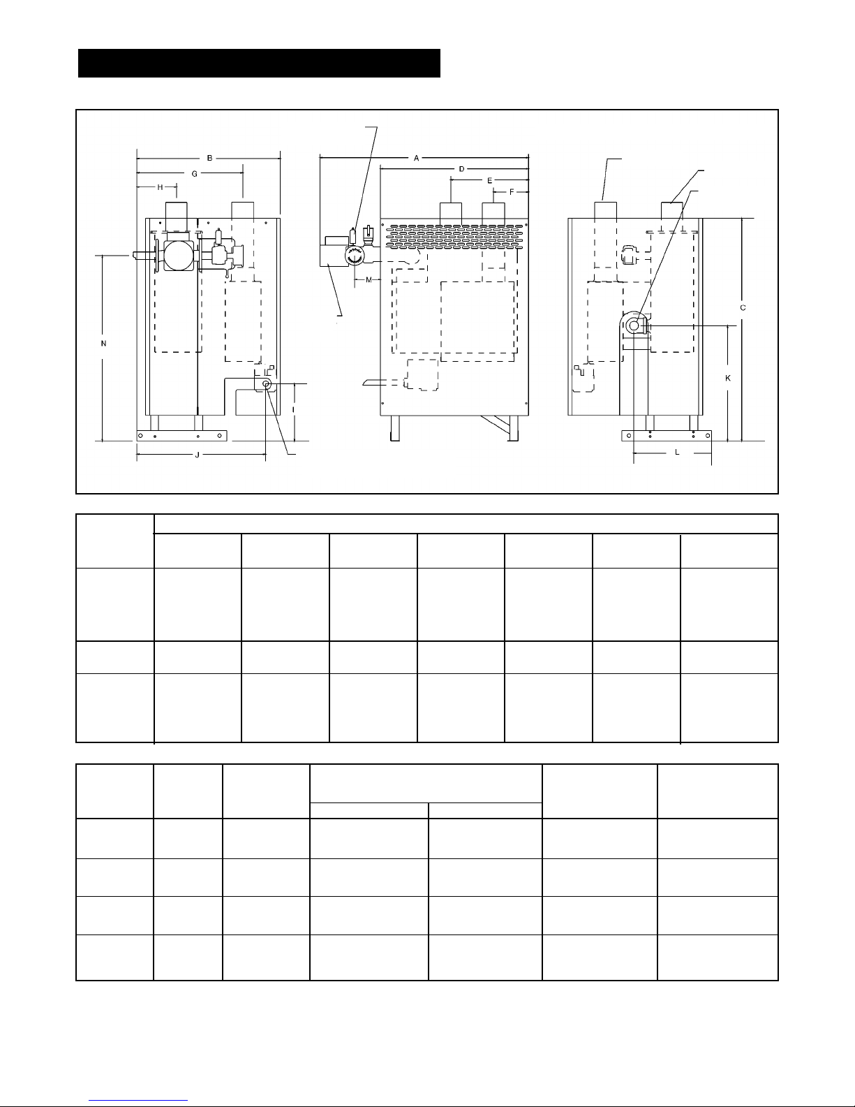
Figure 1. Views — Dimensions — Data
ABCDEFG
mm in mm in mm in mm in mm in mm in mm in
CB-45 743 29.25 508 20 794 31.25 527 20.75 279 11 127 5 356 14
CB-90 743 29.25 584 23 794 31.25 527 20.75 279 11 127 5 432 17
CB-135 743 29.25 660 26 794 31.25 527 20.75 279 11 127 5 508 20
CB-180 743 29.25 737 29 794 31.25 527 20.75 279 11 127 5 584 23
HIJKLMN
mm in mm in mm in mm in mm in mm in mm in
CB-45 127 5 203 8 457 18 413 16.25 273 10.75 95 3.75 660 26
CB-90 165 6.5 203 8 533 21 413 16.25 273 10.75 95 3.75 660 26
CB-135 203 8 203 8 610 24 413 16.25 273 10.75 95 3.75 660 26
CB-180 241 9.5 203 8 686 27 413 16.25 273 10.75 95 3.75 660 26
Boiler
Model
DIMENSIONS INCHES
RATINGS AND DIMENSIONS
Boiler No. of Gas Gas Supply Pressure Shipping Boiler
Model Sections Type Max Min Weight Water Vol.
mm in mm in kg lbs l USG
CB-45 1 Natural 229 9 89 3.5
87 192 1.9 0.5
CB-45 1 Propane 356 14 279 11
CB-90 2 Natural 229 9 89 3.5
112 246 3.8 1.0
CB-90 2 Propane 356 14 279 11
CB-135 3 Natural 229 9 89 3.5
142 312 5.7 1.5
CB-135 3 Propane 356 14 279 11
CB-180 4 Natural 229 9 89 3.5
167 368 7.6 2.0
CB-180 4 Propane 356 14 279 11
WATER SUPPLY
32mm (1 1/4") NPT
GAS SUPPLY
13mm (1/2") NPT
76mm (3") VENT DIA. FOR ALL VENTING, ALL MODELS
AIR INTAKE
EXHAUST
WATER RETURN
32mm (1 1/4")
LEFT SIDE VIEW FRONT VIEW RIGHT SIDE VIEW
CIRC.
PUMP

NOTICE: INSTALLATION AND SERVICE MUST BE
PERFORMED BY A QUALIFIED HEATING CONTRACTOR
The installation must conform to the requirements of
the National Fuel Gas Code ANSI Z223.1 and CSA
B149.1-00 for natural gas and propane for Gas Burning
Appliances and Equipment, and the requirements of the
authority having jurisdiction as well as the requirements
in this instruction manual. In addition, where required by
the authority having jurisdiction, installation must
conform to the Standard for Controls and Safety Devices
for Automatically Fired Boilers, ANSI/ASME CSD-1. If
there is any conflict in the above requirements, then the
more stringent requirement will apply.
BOILER LOCATION
Structure through which venting will pass must be free
and clear for opening (i.e. no hidden conduit, telephone
cables or other obstructions).
Boiler location should be such that the gas ignition
system components are protected from water (dripping,
spraying, rain, etc.) during appliance operation and
service (circulator replacement, condensate trap, control
replacement, etc.).
For a closet installation, ventilation openings must be
provided through a door or wall to prevent excessive
heat build-up. Two openings, one near the floor and one
near the ceiling, should be sized to assure sufficient air
circulation in the closet (minimum 64,516mm
2
[100 sq.
inches] each).
WARNING
LIQUEFIED PETROLEUM (L.P.) PROPANE FIRED
GAS BOILER LOCATION
REQUIRES SPECIAL ATTENTION
Liquefied Petroleum (L.P.) propane gas is heavier than
air. Therefore, propane boilers, piping, valves must NOT
be installed in locations where propane leaking from
defective equipment and piping will "pool" in a basement
or other space below the leak.
A spark or flame from the boiler or other source may
ignite the accumulated propane gas causing an
explosion or fire.
Provide a level, solid foundation for the boiler. Location
should be as near the chimney as possible so that the
flue pipe from boiler to the chimney is short and direct.
The UNIFORM MECHANICAL CODE may be in effect
in your geographic area.
The following precautions are cited by the 1994
UNIFORM MECHANICAL CODE, section 304.6 or CSA
B149.1-00 for natural gas and propane.
“LPG Appliances. Liquefied petroleum gas-burning
appliances shall not be installed in a pit, basement
or similar location where heavier-than-air-gas might
collect. Appliances so fueled shall not be installed in
an above-grade under-floor space or basement
unless such location is provided with an approved
means for removal of unburned gas.”
Consult Chapter 5 of the 1994 UNIFORM MECHANICAL
CODE for design criteria of the "approved" means for
removal of unburned gas.
SAFETY—
KEEP THE BOILER AREA CLEAR AND FREE FROM
COMBUSTIBLE MATERIALS, GASOLINE AND OTHER
FLAMMABLE VAPORS AND LIQUIDS.
BOILER FOUNDATION
A. Provide a solid, level foundation, capable of
supporting the weight of the boiler filled with water,
and extending at least 51mm (2") past the jacket on
all sides. See dimensions of boilers, page 2.
B. Boiler can be installed on both combustible and non-
combustible floors, but must NOT be installed on or
above carpeting.
C. If boiler is to be located over buried conduit
containing electric wires or telephone cables, consult
local codes or the National Board of Fire Underwriters
for specific requirements.
MINIMUM CLEARANCES
A. Minimum clearances to the exterior surfaces of the
boiler shall be as follows:
MINIMUM ALCOVE AND CLOSET CLEARANCE.
B. Provide 457mm (18") on sides used for passage.
For Combustible Recommended
Surface
Construction for Service
Front 51mm (2") 457mm (18")
Rear 51mm (2") 203mm (8")
Left Side 51mm (2") 457mm (18")
Right Side 51mm (2") 457mm (18")
Top 254mm (10") 254mm (10")
Flue Connector 76mm (3") 152mm (6")
C. All minimum clearances shown above must be met.
This may result in increased values of some
minimum clearances in order to maintain the
minimum clearances of others.
D. Clearance from hot water pipes shall be
25mm (1") **.
** At points where hot water pipes emerge from a
floor, wall or ceiling, the clearance at the opening
through the finished floor boards or wall or ceiling
boards may not be less than 13mm (1/2"). Each
such opening shall be covered with a plate of
noncombustible material.
3
INSTALLATION REQUIREMENTS
APPROVED VENTING APPLICATIONS
This Concept 21 boiler is approved to be vented using
Direct Vent, Category I, or Category IV applications.
These applications are differentiated as follows:
Direct Vent — The air for combustion is piped directly to
the air intake of the boiler from outdoors. The vent piping
may be run horizontally or vertically to the outdoors, to a
common terminal with the combustion air intake or
separate from the combustion air intake means.
Category I— The air for combustion is taken from the
ambient air surrounding the boiler. The vent piping must
be upsized and run into a vertical chimney or vent which
will insure a non-positive vent pressure. There is only one
specified input rate for each model boiler on Category I
installations. See chart 2 on page 20.
Category IV— The air for combustion is taken from the
ambient air surrounding the boiler. The vent piping may be
run horizontally or vertically to the outdoors. The vent
pressure is typically positive in this application.
The following venting installation requirements are divided
into 3 sections, each pertaining to the 3 different
applications described above. Once the appropriate
venting application has been selected, follow only the
requirements specified under that section for venting the
boiler. These requirements must be carefully read and
followed in order to avoid any hazardous conditions due to
improper installation of the flue gas venting system.
DIRECT VENT APPLICATION REQUIREMENTS
VENTING LOCATION
Vent installations shall be in accordance with Part 7,
Venting of Equipment, of the National Fuel Gas Code,
ANSI Z223.1, and CSA B149.1-00 for natural gas and
propane, or applicable provisions of local building codes.
Vent termination must meet the following clearances:
Minimum of 305mm (12”) above grade and normal snow
line to vent terminal bottom; minimum of 305mm (12”)
from any building opening; minimum of 914mm (3 feet)
above any forced air intake located within 3048mm (10
feet); minimum of 1219mm (4 feet) horizontally from, and
in no case above or below, unless 1219mm (4-foot)
horizontal distance is maintained, from electric or gas
meters, regulators and relief equipment.
Vent termination must not be located over any public
walkway, in any confined space (i.e. window wells,
alcoves, narrow alleys) or under any overhang or deck.
Vent termination should not allow flue gas discharge
towards neighbor's windows or where personal injury or
property damage can occur.
DO NOT install the vent into a common venting system.
DO NOT install a vent damper or similar device in vent
tubing or on the boiler.
VENT MATERIAL
A. DO NOT use galvanized or plastic vent system
materials. The vent system for Direct Vent Applications
must be UL listed 76mm (3”) diameter corrosion
resistant stainless steel. The following manufacturer’s
systems are approved for use within a specified
minimum and maximum equivalent vent length for each
model of boiler. Refer to Slant/Fin Parts List, Publication
CB 10PL.
B. When joining the various components of the above
listed vent systems, the manufacturers’ instructions
should be closely followed to insure proper sealing
. Use
GE-RTV106 or Dow-Corning 732 sealant for sealing of
pipe and fittings. See Figure 4 for proper application of
vent pipe sealant.
C. All vent connections must be liquid and pressure tight.
4
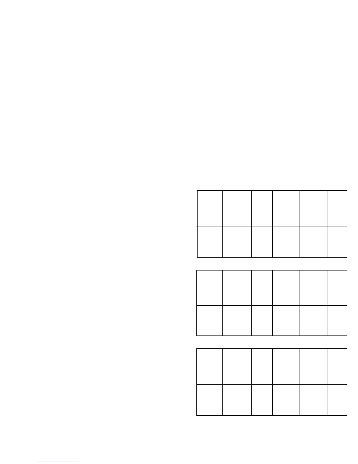
CB-45 30 100 5 914 3 1524 5 1
CB-90 30 100 5 914 3 1524 5 1
CB-135 24 80 5 914 3 1524 5 1
CB-180 12 40 5 914 3 1524 5 1
Boiler
Model
No.
Maximum
Equivalent
Length
including
Elbows
m ft
Max.
No. of
Elbows*
Equivalent
Length of
each
Elbow
mm ft
Minimum
Equivalent
Length*
mm ft
Min.
No. of
Elbows*
* All lengths specified include mandatory minimum use of 610mm (2
feet) of tubing plus one elbow from boiler to vent termination all
models.
Heat Fab Saf-T Vent System
CB-45 30 100 5 1829 6 2438 8 1
CB-90 30 100 5 1829 6 2438 8 1
CB-135 18 60 5 1829 6 2438 8 1
CB-180 9 30 3 1829 6 2438 8 1
Boiler
Model
No.
Maximum
Equivalent
Length
including
Elbows*
m ft
Max.
No. of
Elbows*
Equivalent
Length of
each
Elbow
mm ft
Minimum
Equivalent
Length*
mm ft
Min.
No. of
Elbows*
ProTech Fas-N Seal System
CB-45 30 100 5 1829 6 2438 8 1
CB-90 30 100 5 1829 6 2438 8 1
CB-135 21 70 5 1829 6 2438 8 1
CB-180 11 35 4 1829 6 2438 8 1
Boiler
Model
No.
Maximum
Equivalent
Length
including
Elbows*
m ft
Max.
No. of
Elbows*
Equivalent
Length of
each
Elbow
mm ft
Minimum
Equivalent
Length*
mm ft
Min.
No. of
Elbows*
Flex-L Star-34 System

Figure 2. General Vent and Air Intake Piping from Boiler
for Direct Venting
All items shown below are REQUIRED. All vent
joints must be LIQUID and PRESSURE TIGHT.
Figure 3. Floor and ceiling venting passage
All items shown below are REQUIRED.
All vent joints must be LIQUID and PRESSURE TIGHT.
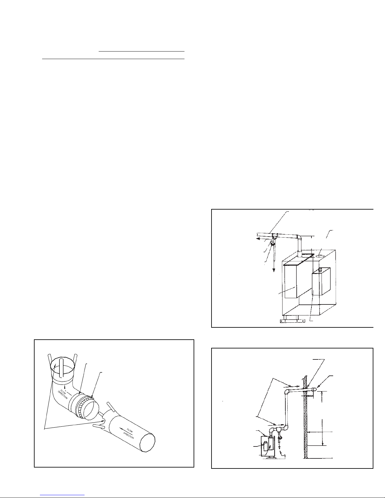
Figure 4. Vent sealing instructions
(Consult vent manufacturer’s instructions.)
5
DIRECT VENT APPLICATION REQUIREMENTS
AIR INTAKE
A. 76mm (3”) diameter PVC piping materials are
recommended. Sewer and drain type material or PVC
schedule 40 piping are best suited for connection to
boiler and vent terminal. Use 76mm (3”) PVC fitting
provided with vent kit to adapt PVC schedule 40 air
intake tubing to air filter box collar. The fitting provided
will fit onto the filter box collar and then a schedule 40
76mm (3”) coupling will fit over that.
B. The venting length requirements specified in this
section also apply to the air intake piping.
C. Seal all joints on air intake piping using appropriate
sealants.
VENTING INSTALLATION
A. Follow the vent material manufacturer’s instructions in
conjunction with these instructions for venting system
installation.
B. Refer to Figures 2, 3 and 4 which illustrate some of
the requirements for venting in a typical installation.
C. A condensate drain and drain trap MUST be installed
on the flue tubing, see Figure 2. The condensate
drain should be installed close to the boiler, as
shown, and must be equipped with a trap formed by
attaching 10mm (3/8”) I.D. clear plastic tubing to the
drain assembly, making a loop approximately 102mm
(4") diameter and securing with cord or a tie wrap
where the loop crosses over itself. This loop should
then be filled with water to form a liquid-filled trap.
DO NOT OPERATE THE BOILER WITHOUT
INSTALLING THIS TRAP AND FILLING WITH WATER
EXHAUST VENT PIPING 76mm (3”) I.D.
AIR INTAKE PIPING 76mm (3”) I.D.
76mm
(3”) PVC
FITTING.
152mm (6”)
MIN. 610mm
(24”) MAX.
CONTINUE WITH PIPING
AS SHOWN IN
FOLLOWING FIGURES
SLOPE UP
20mm/m (1/4”/FT)
CONDENSATE
DRAIN ASSY
FILL TRAP WITH
WATER
HEAT EXCHANGER
ASSY
TO DRAIN
AIR FILTER BOX ASSY
VENT SEALING INSTRUCTIONS FOR HEAT-FAB 29-4C
STAINLESS STEEL VENTING MATERIALS
RING
APPLY ADHESIVE BEAD (6mm [1/4”] DIA. MINIMUM)
AROUND OUTSIDE OF MALE END ONLY, BETWEEN
6mm (1/4”) AND 10 mm (3/8”) FROM THE EDGE OF
THE MALE END. CARE MUST BE TAKEN TO ASSURE
THAT ADHESIVE DOES NOT BLOCK INSIDE OF PIPE
DO NOT APPLY ADHESIVE INSIDE
OF FEMALE FITTINGS IN ORDER TO PREVENT
BLOCKAGE OF INSIDE OF FITTINGS AND TUBING.
IF ANY ADHESIVE SHOULD GET INSIDE, BE SURE
TO WIPE IT OUT BEFORE ASSEMBLING
FIRESTOP
EXHAUST VENT TUBING
76mm (3”) I.D.
CLEARANCE: 152mm
(6”) MIN. FOR 29-4C
STAINLESS STEEL
VENTING
FIRESTOP AND SUPPORT
AIR INTAKE
TUBING 76mm
(3”) I.D.
CLEARANCE:
51mm (2”) MIN.
BETWEEN TUBING
76mm (3”)
MIN. 610mm
(24”) MAX.
TO PREVENT FLUE GAS DISCHARGE INTO SPACE.
Periodic inspection should be made of this assembly for
deterioration of the tubing and to insure that the trap is
filled with water, but not plugged. If it is plugged or
appears to have excessive sediment in it, it should be
removed from the drain assembly, straightened out to clear
the obstruction, reformed, filled with water and reinstalled
as before. The drain must extend to a floor drain.
D. The horizontal pipe must be sloped UPWARD from
the boiler, at a pitch of 20mm/m (*1/4” per 1 foot) of
run, so that the condensate from the vent system runs
to the drain trap. The horizontal portion must also be
supported with 19mm (3/4”) pipe strap at intervals no
greater than 1829mm (6 feet).
E. The vertical portion of the pipe must be supported in
at least one location for each 9m (30 feet) of vertical
run. A firestop is required for each wall, ceiling and
floor penetration.
F. Use tabs on vent collar to secure stainless steel vent
tubing to the boiler.
G. Venting is approved for combustible wall passage
through a 102mm (4”) minimum to 305mm (12”)
maximum thick wall, providing a thimble is used.
6
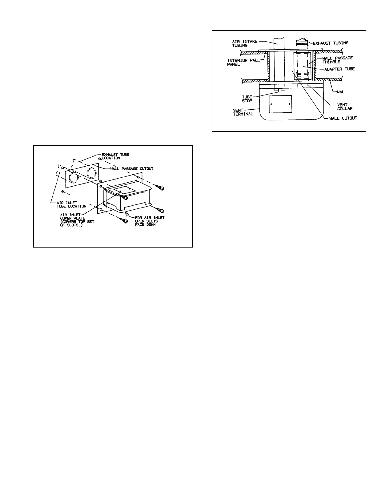
Figure 5a. Vent terminal orientation
Figure 5b. Vent terminal installation
VENT TERMINAL INSTALLATION
Warning: The vent terminal provided is to be used for
horizontal venting only. DO NOT alter this part in any
manner other than shown in these instructions. Only mount
on a vertical surface. DO NOT use when vertically venting
through a roof or chimney.
1. Wall cutout opening:
a) Cut out a rectangular opening 152mm (6”) high and
305mm (12”) wide in the appropriate location of an
exterior wall. Be sure that this location will allow for
the connection of vent materials that come in fixed
lengths, or an adjustable connector will be needed.
b) Boxing in the cutout with wood is allowable, but the
152mm x 305mm (6” x 12”) opening size must be
maintained.
c) Plan on the edge of the cutout to be about 76mm (3”)
from the center of the exhaust tube, when installed.
2. Vent terminal orientation: see Figure 5a.
a) The open slots for the air intake on the vent terminal
must face downward.
b) The air inlet cover plate must face upward to insure
that rain, debris and flue gases do not enter the air
inlet.
3. Vent and air intake tubing orientation: see Figure 5a.
a) Air inlet tubing may be located to the left or to the
right of the flue exhaust tubing.
b) If the air inlet tubing is going to be to the left of the
flue exhaust (viewed from outside of building) then
the vent terminal should be installed as supplied
without alteration.
c) If the air inlet tubing is going to be to the right of t
flue exhaust (viewed from outside building) then t
air inlet cover plate must be removed and reinstall
over the alternate set of slots. This alteration w
insure that the air inlet slots face down when the ve
terminal is installed.
4. Vent terminal installation: see Figure 5b.
a) Center the vent terminal over the wall cutout. T
collar on the back of the vent terminal panel shou
clear the cutout edges by about 12mm (1/2”).
b) Mark and drill out the location of the four screw hol
in the wall for mounting vent terminal.
c) Seal the vent collar adapter tube 76mm (3”) dia. ma
end stainless) into the collar on the back of the ve
terminal box and slide the ring on the tube over t
collar tabs, then bend the tabs back over the rin
This piece will allow easy connection of the fl
exhaust tubing from inside the building.
d) Run a bead of silicone around the perimeter of w
panel and vent collar to prevent water and drafts fro
entering building.
e) Orientate the vent terminal on the wall as describ
in Step 2 and secure it to the wall.
5. Interior wall panel installation:
a) Cut the wall thimble 127mm (5”) diameter galv. pip
about 12mm (1/2”) shorter than the wall thickness
b) Fit thimble onto the collar on the back of the ve
terminal inside the wall.
c) Hold the interior wall panel up to the wall cutout a
fit the collar on this panel into the thimble. Line up t
air inlet holes and secure to wall.
6. Vent and air intake tubing installation to vent terminal:
a) Finish tubing connections back to the boil
following
the requirements in the venting installati
instructions
on pages 4 and 5.
b) Exhaust tubing connects to the vent collar adapt
tube. Observe correct flow direction.
c) Air intake tubing should slip into the air inlet openi
in the back of the vent terminal. Make sure the tubi
extends into the vent terminal box as far as the tu
stop inside the box allows (19mm [3/4”] approx
Seal around the air intake tubing where it pass
through the outside wall plate.
*Shown with air inlet to the left of exhaust
from outside view.
* Shown from top view.
DIRECT VENTING WITH VENT TERMINAL
All Concept 21 boiler models are certified for horizontal
Direct Venting utilizing the vent terminal provided by
Slant/Fin only.
This vent terminal must be mounted on a vertical wall
outside surface. Terminal CANNOT be mounted on a roof
or any horizontal surface.
Vent terminal is designed to deflect flue gases away from
outside building wall; properly installed, it will prevent flue
gas degradation of normal building materials and reduce
the possibility of air intake freeze-up. It is recommended
to utilize this vent terminal on Direct Vent applications
whenever the installation permits.

Figure 7a. Vent and air intake run through a pitched roof
Figure 7b. Vent and air intake run through a flat roof
7
EXHAUST WITH SCREEN
AIR INTAKE 180° ELBOW
WITH SCREEN FACE
DOWN
3048mm (10 ft)
or less
610mm (2 ft) min.
ROOF FLASHING
54mm (2“) min.
305mm
(1 ft) min.
54mm (2“) min.
ROOFLINE
SNOWLINE
EXHAUST WITH
SCREEN
3048mm (10 ft)
or less
610mm (2 ft) min.
ROOF
LINE
SNOW
LINE
ROOF FLASHING
54mm (2”) min.
54mm (2”) min.
AIR INTAKE 180° ELBOW
WITH SCREEN FACE DOWN
305mm (1 ft) min.
305mm (1 ft) min.
914mm
(3 ft)
min.
305mm
(1 ft) min.
914mm
(3 ft) min.
Vertical Venting Configurations
All Concept 21 boiler models are certified for vertical
Direct Venting utilizing the following configurations.
1. Vent and air intake piping vertically run up through a
roof in close proximity.
a. For a pitched roof installation, refer to Figure 7a. For
a flat roof installation, refer to Figure 7b. When floor
and ceiling passage is necessary, refer to Figure 3.
Adhere to all clearances and materials specified in
these illustrations.
b. The stainless exhaust vent pipe must pass through
the roof vertically through a 178mm (7”) min.
diameter cutout and appropriate roof flashing. The
pipe must exhaust straight up and terminate with a
screen terminator.
c. The air intake pipe must pass through the roof
vertically. The cutout does not require any clearance,
but must be sealed with a flashing or other means.
The air intake opening must face down by using a
180° elbow with a screen positioned at the opening.
The air intake opening must be at least 305mm (1
foot) below the vent opening.
DIRECT VENTING WITHOUT VENT TERMINAL
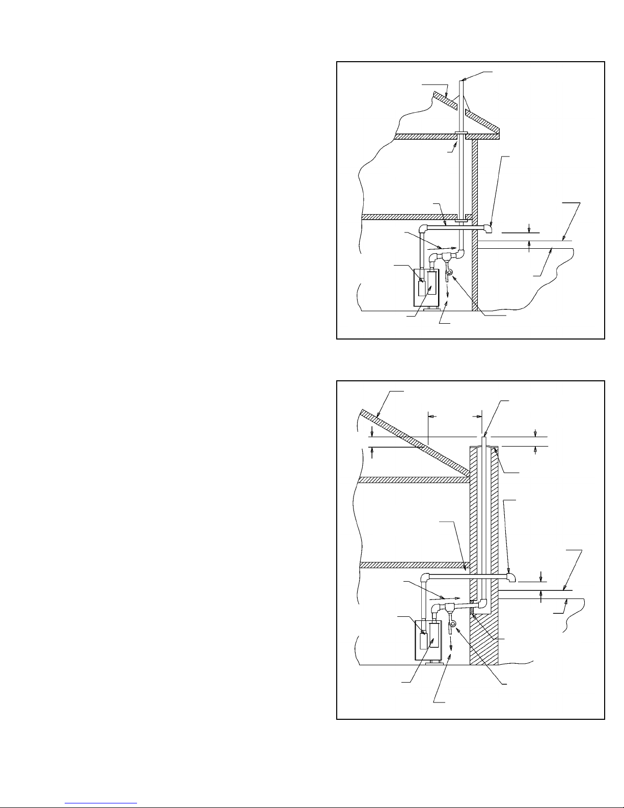
Figure 8b. Vent piping vertically run up an existing chimney
and air intake horizontally run out a vertical wall.
Figure 8a. Vent run through a roof and air intake run through
a wall
8
REFER TO VENT PIPE
REQUIREMENTS SHOWN IN
PREVIOUS FIGURES FOR
VENT AND AIR INTAKE RUN
THROUGH A PITCHED OR
FLAT ROOF
EXHAUST WITH SCREEN
AIR INTAKE 90° ELBOW WITH
SCREEN FACE DOWN
SNOWLINE
305mm (1 ft) min.
GROUNDLINE
CONDENSATE DRAIN ASSY
TO DRAIN
HEAT EXCHANGER
ASSY
AIR FILTER
BOX ASSY
Slope up
20mm/m
(1/4” per ft)
RUN AIR INTAKE PIPE
THROUGH THE
FOUNDATION OR AN
EXTERIOR WALL
REFER TO
PREVIOUS FIGURE
FOR FLOOR AND
CEILING PASSAGE
ROOF LINE
3048mm
(10 ft) or
less
EXHAUST WITH
SCREEN
305mm (1 ft) min.
CHIMNEY TOP PLATE
AIR INTAKE 90° ELBOW
WITH SCREEN FACE
DOWN
SNOWLINE
305mm (1 ft) min.
GROUNDLINE
CONDENSATE DRAIN ASSY
TO DRAIN
HEAT EXCHANGER
ASSY
AIR FILTER
BOX ASSY
SLOPE UP
20mm/m
(1/4” per ft)
RUN AIR INTAKE PIPE
THROUGH THE
FOUNDATION OR AN
EXTERIOR WALL
SEAL CHIMNEY OPENING
WITH MORTAR OR
COVER PLATE
610mm
(2 ft) min.
Vertical Venting Configurations
2. Vent piping vertically run up through a roof and air
intake horizontally run out a vertical wall.
a. See Figure 8a for general configuration. For a
pitched roof installation, refer to vent pipe
requirements shown in Figure 7a. For a flat roof
installation, refer to the vent pipe requirements
shown in Figure 7b. When floor and ceiling passage
is necessary, refer to Figure 3. Adhere to all
clearances and materials specified in these
illustrations for installing the vent pipe only. For
installing the air intake pipe, refer to the air intake
requirements shown in Figure 8a.
b. The stainless exhaust vent pipe must pass through
the roof vertically through a 178mm (7”) min.
diameter cutout and appropriate roof flashing. The
pipe must exhaust straight up and terminate with a
screen terminator.
c. The air intake pipe must pass through a vertical wall
or foundation horizontally. The cutout does not
require any clearance, but must be sealed with a
flashing or by other means. The air intake opening
must face down by using 90° elbow with a screen
positioned at the opening.
3. Venting piping vertically run up an existing chimney
and air intake horizontally run out a vertical wall.
a. Refer to Figure 8b. Adhere to all clearances and
materials specified in this illustration.
b. The stainless exhaust vent pipe must extend the
total length of the chimney. The pipe must exhaust
straight up and terminate with a screen terminator.
The top of the chimney must be sealed off around
the protruding pipe with an appropriate plate or
flashing. Other appliances CANNOT be vented into
the same chimney or vent pipe within the chimney.
c. The air intake pipe must pass through a vertical wall
or foundation horizontally. The cutout does not
require any clearance, but must be sealed with a
flashing or by other means. The air intake opening
must face down by using a 90° elbow with a screen
positioned at the opening.
DIRECT VENTING WITHOUT VENT TERMINAL
BOILER ROOM AIR SUPPLY AND VENTILATION
An ample supply of air is required for combustion and
ventilation. When buildings are insulated, caulked and
weather-stripped, now or later on, direct openings to outside
may be required and should be provided. If the boiler is not
near an outside wall, air may be ducted to it from outside
wall openings.
Provisions for combustion and ventilation air must be made
in accordance with section 5.3, Air for Combustion and
Ventilation, of the National Fuel Gas Code, ANSI Z223.1 and
CSA B149.1-00 for natural gas and propane
, or applicable
provisions of the local building codes. The following
recommendation applies to buildings of energy-saving
construction, fully caulked and weather- stripped:
Provide one GRILLED opening near the floor and one near
the ceiling on an outside wall near the boiler (or duct from
such openings to the boiler), EACH opening to be a
minimum of 645mm
2
(one square inch) per 586w (2000 Btuh)
input to ALL
APPLIANCES in the area. For a total appliance
input of 58 620w
(200,000 Btuh), each opening will be 64 516
mm
2
(100 square inches). A grilled opening 254mm x 254mm
(10"X10") has 64 516mm
2
(100 square inches) of area. If fly
screen must be used over openings, double the area and
inspect and clean the screen frequently.
Openings must never be reduced or closed. If doors or
windows are used for air supply, they must be locked open.
Protect against closure of openings by snow and debris.
Inspect frequently.
No mechanical draft exhaust or supply fans are to be used in
or near the boiler area.
The flow of combustion and ventilating air to the boiler must
not be obstructed.
The air inlet passage hole located on the top of the boiler
jacket should be covered for any installation which does not
require combustion air to be piped into the boiler. (i.e. Direct
Vent Installation)
VENTING LOCATION REQUIREMENTS
Vent installations shall be in accordance with Part 7, Venting
of Equipment, of the National Fuel Gas Code, ANSI Z223.1
and
CSA B149.1-00 for natural gas and propane, or
applicable provisions of local building codes.
This Concept 21 boiler is approved for pressure venting both
horizontally and vertically. The following requirements apply
to both types of venting installation.
Vent termination must meet the following clearances:
Minimum of 305mm (12”) above grade and normal snow line
to vent termination bottom; minimum of 1219mm (4 feet)
below or horizontally, or 305mm (1 foot) above any building
opening; minimum of 914mm (3 feet) above any forced air
intake located within 3048mm (10 feet); minimum of 1219mm
(4 feet) horizontally from, and in no case above or below,
unless 1219mm (4-foot) horizontal distance is maintained,
from electric or gas meters, regulators and relief equipment.
Vent termination must not be located over any public
walkway, in any confined space (i.e. window wells,
alcoves, narrow alleys) or under any overhang or deck.
Vent termination should not allow flue gas discharge
towards neighbor's windows or where personal injury or
property damage can occur.
DO NOT install the vent into a common venting system.
DO NOT install a vent damper or similar device in vent
tubing or on the boiler.
VENT MATERIAL REQUIREMENTS
A. DO NOT use galvanized or plastic vent system
materials. The vent system for Category IV applications
must be UL listed 76mm (3”) diameter corrosion
resistant stainless steel. The following manufacturer’s
systems are approved for use within a specified
minimum and maximum equivalent vent length for each
model of boiler.
Category IV Venting Requirements
CB-45 30 100 5 914 3 1524 5 1
CB-90 30 100 5 914 3 1524 5 1
CB-135 24 80 5 914 3 1524 5 1
CB-180 12 40 5 914 3 1524 5 1
Boiler
Model
No.
Maximum
Equivalent
Length
including
Elbows
m ft
Max.
No. of
Elbows*
Equivalent
Length of
each
Elbow
mm ft
Minimum
Equivalent
Length*
mm ft
Min.
No. of
Elbows*
* All lengths specified include mandatory minimum use of 610mm (2
feet) of tubing plus one elbow from boiler to vent termination all
models.
Heat Fab Saf-T Vent System
CB-45 30 100 5 1829 6 2438 8 1
CB-90 30 100 5 1829 6 2438 8 1
CB-135 18 60 5 1829 6 2438 8 1
CB-180 9 30 3 1829 6 2438 8 1
Boiler
Model
No.
Maximum
Equivalent
Length
including
Elbows*
m ft
Max.
No. of
Elbows*
Equivalent
Length of
each
Elbow
mm ft
Minimum
Equivalent
Length*
mm ft
Min.
No. of
Elbows*
ProTech Fas-N Seal System
CB-45 30 100 5 1829 6 2438 8 1
CB-90 30 100 5 1829 6 2438 8 1
CB-135 21 70 5 1829 6 2438 8 1
CB-180 11 35 4 1829 6 2438 8 1
Boiler
Model
No.
Maximum
Equivalent
Length
including
Elbows*
m ft
Max.
No. of
Elbows*
Equivalent
Length of
each
Elbow
mm ft
Minimum
Equivalent
Length*
mm ft
Min.
No. of
Elbows*
Flex-L Star-34 System
B. When joining the various components of the above
listed vent systems, the manufacturers’ instructions
should be closely followed to insure proper sealing. Use
GE-RTV106 or Dow-Corning 732 sealant for sealing of
pipe and fittings. See Figure 4 for proper application of
vent pipe sealant.
C. All vent connections must be liquid and pressure tight.
VENTING INSTALLATION
A. Follow the vent material manufacturer’s instructions in
conjunction with these instructions for venting system
installation.
B. Refer to Figures 4 and 9 which illustrate some of the
requirements for venting in a typical installation.
C.
A condensate drain and drain trap MUST be installed on
the flue tubing, see Figure 9. The condensate drain should
be installed close to the boiler, as shown, and must be
equipped with a trap formed by attaching 9mm (3/8") I.D.
clear plastic tubing to the drain assembly, making a loop
approximately 102mm (4") diameter and securing with cord
or a tie wrap where the loop crosses over itself. This loop
should then be filled with water to form a liquid-filled trap.
DO NOT OPERATE THE BOILER WITHOUT INSTALLING
THIS TRAP AND FILLING WITH WATER TO PREVENT
FLUE GAS DISCHARGE INTO SPACE. Periodic inspection
should be made of this assembly for deterioration of the
tubing and to insure that the trap is filled with water, but not
plugged. If it is plugged or appears to have excessive
sediment in it, it should be removed from the drain
assembly, straightened out to clear the obstruction,
reformed, filled with water and reinstalled as before. The
drain must extend to a floor drain.
D. The horizontal pipe must be sloped UPWARD from the
boiler, at a pitch of 20mm/m (1/4” per 1 foot) of run, so
that the condensate from the vent system runs to the
drain trap. The horizontal portion must also be
supported with 19mm (3/4”) pipe strap at intervals no
greater than 1828mm (6 feet).
Category IV Venting Requirements
E.
The vertical portion of the pipe must be supported in at leas
one location for each 9m (30 feet) of vertical run. A firestop
is required for each wall, ceiling and floor penetration.
F. Use tabs on vent collar to secure stainless steel vent
tubing to the boiler.
G. Venting is approved for combustible wall passage
through a 102mm (4”) minimum to 305mm (12”)
maximum thick wall, providing a thimble is used.
HORIZONTAL CATEGORY IV VENTING
All Concept 21 boiler models are certified for horizontal
Category IV venting provided the following conditions are met
1. For combustible wall passage of vent piping, a UL and
CUL listed thimble must be used, providing the wall
thickness is 102mm (4”) minimum to 305mm (12”)
maximum.
2. The venting piping must terminate with a screened tee,
elbow, or straight termination at the minimum distance
from the outside wall shown in Figure 10.
10
Figure 9. General Vent Piping from Boiler for Category IV Ventin
All items shown below are REQUIRED.
All vent joints must be LIQUID and PRESSURE TIGHT.
Figure 4. Vent sealing instructions
(Consult vent manufacturer’s instructions.)
Figure 10. Horizontal Category IV Venting through outside wall
CONTINUE WITH VENT
PIPING AS SHOWN IN
FOLLOWING FIGURES
EXHAUST VENT
PIPING 76MM (3”) I.D.
AIR INLET COVER
203mm (8”) MIN.
610mm (24”) MAX.
AIR FILTER BOX ASSY.
HEAT
EXCHANGER
ASSY.
TO DRAIN
FILL TRAP WITH WATER
CONDENSATE DRAIN ASSY.
SLOPE UP 20mm/m (1/4” PER FT.)
76mm (3”) MIN.
610mm (24”) MAX.
VENT SEALING INSTRUCTIONS FOR HEAT-FAB 29-4C
STAINLESS STEEL VENTING MATERIALS
RING
APPLY ADHESIVE BEAD (6mm [1/4”] DIA.
MINIMUM) AROUND OUTSIDE OF MALE END ONLY,
BETWEEN 6mm (1/4”) AND 9mm (3/8”) FROM THE
EDGE OF THE MALE END.
CARE MUST BE TAKEN TO ASSURE THAT
ADHESIVE DOES NOT BLOCK INSIDE OF PIPE
DO NOT APPLY ADHESIVE INSIDE
OF FEMALE FITTINGS IN ORDER TO
PREVENT BLOCKAGE OF INSIDE OF
FITTINGS AND TUBING. IF ANY ADHESIVE
SHOULD GET INSIDE, BE SURE TO WIPE IT
OUT BEFORE ASSEMBLING
WALL
THIMBLE
VENT
TERMINATION
WITH SCREEN
305mm
(1 FT.)
MIN.
OUTSIDE WALL
SNOW LINE
GROUNDLINE
HEAT EXCHANGER
ASSY.
AIR FILTER BOX
ASSY.
AIR INLET COVER
VENT PIPE
SLOPE UP 20mm/m
(1/4” PER FT.)
102mm
(4”)
MIN.
TO
DRAIN
 Loading...