

Page 1

SERVICE MANUAL
8M27 A/E/S/B CHASSIS
Page 2

1. PFS
2. BLOCK DIAGRAM
3. LIST OF KEY PARTS
4. IC BLOCK DOAGRAM
5. CIRCUIT DIAGRAM
6. MAIN PCB
7. USE MAUNAL
Page 3
(ETD/ETA)
(
Gostandard/CE/MPTT/CB/U
(
Gostandard/CE/MPTT/C
8M27 CHASSIS PFS(production feature specification)
Model #
Production content
ID for reference only
Country( West Eu./East
Eu./Russia/AP/US/S.A./Japan/
…)
Brand name
Category
(Monitor/TV/Combo/Portable
TV…)
TV Type(ATV、DTV(DVBT/DVB-T2/DTMB/ATSC/ISDBT…))
Panel technology (LCD /
LED/PDP)
Market Position
(High/Mid/Access,,,)
机芯机型型号 8M27 E57系
列
主要内容
产品造型(图)
国家(西欧/东欧/俄罗斯/
亚太/美国/南非/日本...)
品牌名称
品类(显示器/电视机/组合
产品/移动电视)
TV Type(ATV、
DTV(DVB-T/DVBT2/DTMB/ATSC/ISDB-T
屏体技术
(LCD/LED/PDP)
市场定位(高/中/低)
A E S B
AP AP S.A S.A
TV TV TV TV
ATV ATV+D
LED LED LED LED
LOW-class LOW-
8M27
E57系
VBT,ATV+
class
8M27
E57系列
ATV ATV+ISD
LOWclass
8M27 E57
系列
B-T
LOWclass
Cabinet Design (Example:
01,23 series )
Product NO.
Chassis solution(IC)
Chassis name
Chassis PCB Standard
Predecessor (replace,Base
mark)
Status( Pre./Finish )
Status(PP/Finish )
MP date requested (ETD)
MP date confirmed by supplier
Regional requirement
Homologation
RoHS ROHS RoHS RoHS RoHS RoHS
货柜设计(如:01、23系
列)
产品型号(机壳)
设计方案(IC)
机芯名称
PCB板标准
参考样机或被替代产品
状态(预研/完成)
状态(试产/完成)
量产要求时间(预计的发
货时间)
量产要求时间(预计的发
区域需求
认证
MST6E182X
DT-UZ
SKYWORTH SKYW
CB CB CB CB
MSD13
ORTH
MST6E
182XDT MSD1306
SKYWO
RTH
SKYWOR
TH
PSU Description
PSU P/N
电源描述
电源料号、型号
Page 4
PSU PCB Dimension
Annual
Type(MVA/PVA/IPS/…)
LTI/CTI/BLE/WLE
POP
电源PCB尺寸
Power supply(100-240V AC +/10%/...)
Power consumption working /
Power consumption standby
Power plug(VDE/UL/BS/…)
Picture display
Screen size : diagonale (inch)
Aspect ratio (16/9 // 4/3 // 15/9)
1st panel supplier : panel
suppliers
Luminance
Colour Temp@ maximum
brightness
Horizontal and vertical viewing
angle
Contrast ratio
Typical panel Life Time
电源输入(100-240V AC
+/-10%/...)
功率消耗/每年
待机功耗
电源插头
(VDE/UL/BS/...)
图像显示
屏幕尺寸:对角线(英
宽高比(16:9/4:3/15:9)
第一屏体供应商:
亮度
色温
视角
对比度
屏体寿命
AC 100240V
TBD TBD TBD TBD
<1W <1W <1W <1W
TBD TBD TBD TBD
TBD TBD TBD TBD
AC 100240V
AC 100240V
AC 100240V
second panel supplier : panel
reference
Panel Display
1st panel supplier : resolution
Dynamic contrast ratio
Video signal process
Comb Filter (2D/3D)
Noise Reduction
Picture improvement (
LTI/CTI,BLE,WLE,...)
Color process (Gama
correction/Skin correction /... )
Colour preset
(Cool/Normal/Warm/Personal)
Picture control (
Bright/Con./Sharpness/Color/Ti
Picture presets : Standard /
Bright / Soft / User
Picture freeze
第二屏体供应商
面板显示种类
第一面板供应商:解决方
动态对比度
视频信号处理
梳状滤波(2D/3D)
降噪技术(适度/3D等)
画质提升技术
(
彩色信号处理(伽玛校正/
趋肤效应校正)
色彩设置(冷/标准/暖和/
个性)
图像控制(
Bright/Con./Sharpness/Col
图像设置(标准/明亮/柔和
/用户)
图像冻结
)
TBD TBD TBD TBD
TBD TBD TBD TBD
TBD TBD TBD TBD
3D 3D 3D 3D
3D 3D 3D 3D
Mstar ACE-
5UC
Yes Yes Yes Yes
Neutral/War
m/Cool
Bright/Con./
Sharpness/C
Bright /
Normal/Soft /
Yes Yes Yes Yes
Mstar
ACE-
Neutral/
Warm/C
Bright/C
on./Sha
Bright /
Normal/
Mstar
ACE-
Neutral/
Warm/C
Bright/C
on./Shar
Bright /
Normal/
Mstar
ACE-5UC
Neutral/W
arm/Cool
Bright/Con
./Sharpnes
Bright /
Normal/So
Multi picture : PIP ( AV )/POP
(AV)
Dynamic Backlight Control
多画面(PIP画中画和
画中画)
动态背光调节
No No No No
No No No No
Page 5
Backlight
capability
)
M,N
)
M,N
M,N
背光源
Yes Yes Yes Yes
Deinterlacer (No/linerar/motion
adaptive/motion compensative)
Film mode / reverse 3:2/2:2
pull down
Full HD support ( 1080P )
Single scan / Dual scan (
Zoom type : 4/3 format
Zoom type : 16/9 Format
Zoom type : Auto ( by SCART
Pin8 and WSS )
Picture Auto adjustment (PC
Sound
Sound type ( Mono/AV
Music Power (Watt)/RMS
Power (Watt)
Tone control ( Bass&Treble /
Graphic Equalizer )
Special sound effect ( AVL /
WIDE / Pseudo /… )
Suround system ( Dolby / VD /
SRS / BBE / … )
Sound control ( Volume ,
Balance , Mute )
Sound presets
(User/Speech/News/Standard)
Headphone volume control (
Separated / linked )
Sound quality ( High / Mid /
Low )
Reception and Decoding
逐行转换(没有/线性/运动
自适应/运动补偿)
电影模式/3:2翻转 或2:2拉
伸
支持全高清(1080P)
单扫描及双扫描(120Hz)
放大类型:4:3格式
放大类型:16:9格式
放大类型:自动(以8PIN
SCART 和WSS)
图像自动调整(电脑模式)
声音
声音类别(单声道/AV 立体
伴音功率(单位为瓦特)/
有效功率(单位为瓦特)
音调控制(低音&高音/图示
均衡器)
特殊的声音效果
(AVL/WIDE/Pseudo)
环绕声系统(Dolby / VD /
SRS / BBE / … )
声音控制(音量、平衡、
静音)
声音设置(用户模式/演讲
模式/新闻模式/标准模式)
耳机声音控制(独立的/关
联的)
声音质量(高/中/低)
接收和解码能力
Yes Yes Yes Yes
3:2/2:2 pull
down
3:2/2:2
pull
3:2/2:2
pull
3:2/2:2
pull down
Yes Yes Yes Yes
Single scan Single
Single
Single
Yes Yes Yes Yes
Yes Yes Yes Yes
WSS WSS WSS WSS
Yes Yes Yes Yes
Stereo Stereo Stereo Stereo
19"/22":1.5W
X2
23"/24":3WX
Bass&Treble Bass&T
19"/22":
1.5WX2
23"/24":
reble
19"/22":
1.5WX2
23"/24":
Bass&Tr
eble
19"/22":1.
5WX2
23"/24":3
Bass&Tre
ble
AVL AVL AVL AVL
Surround SurroundSurroundSurround
Volume,Bala
nce,Mute
Standard/Mu
sic/News/Fil
Volume,
Balance
Standar
d/Music/
Volume,
Balance
Standar
d/Music/
Volume,B
alance,Mu
Standard/
Music/Ne
LINKED LINKED LINKED LINKED
LOW LOW LOW LOW
RF range(ATV)
RF range(DTV)
Color System
(PAL/SECAM/NTSC/PAL M,N
Audio Standard (
B/G/H/D/K/K'/I/L/L' )
Stereo audio system (
Nicam,MTS,A2,….)
Video standard NTSC 3.58 /
4.43 (AV)/PAL 60
RF范围(ATV)
RF范围(DTV)
彩色制式
(PAL/SECAM/NTSC/PAL
音频标准
(B/G/H/D/K/K'/I/L/L' )
立体音频系统(
Nicam,MTS,A2,….)
视频标准 NTSC 3.58 / 4.43
(AV)/PAL 60
45MHz ~
45MHz ~
PAL/NTSC/S
ECAM
45MHz
45MHz
PAL/SE
CAM
45MHz
45MHz
NTSC-
M,PAL-
45MHz ~
45MHz ~
NTSC-
M,PALDK/I/BG/M DK/I/BG/MM/N M/N
NICAM/A2 NICAM/A2BTSC BTSC
NTSC3.58/4.
43,PAL50/60
NTSC3.
58/4.43,
NTSC3.
58/4.43,
NTSC3.58
/4.43,PAL
Page 6
DTV SD support (DVB-T/S/C ,
VI/MPEG2/WMV- HD/SD
Lv3.0/4.0) /
AVC
AVC
VC
ROM/DVD+R/+RW/-R/-
ROM/DVD+R/+RW/-R/-
ATSC , QAM , … )
DTV HD Support
MHEG5 MHEG5 No No No No
GINGA GINGA No No No No
数字标清支持(DVB-T/S/C ,
ATSC , QAM , … )
数字高清支持
No DVB-
T/DVBT2
No No No No
No ISDB-T
HD capability with YPbPr
PC capability (up to maximum
format)
HDMI capability (AV/PC
Format)
Compatible video format if
DVD/USB:
Compatible audio format if
DVD/USB:
Playable Discs (CD/CDR(RW)/CD-
Card reader format
Macrovision
PVR
TV 3D feature
PR
分量高清解码能力
PC通道解码能力(最大范
围的格式)
HDMI解码能力(AV/PC 格
式)
USB的视频支持格式:
DviX/VCD/SVCD/JPEG/A
USB的音频支持格式:
DviX/VCD/SVCD/JPEG/A
可播放的Discs (CD/CDR(RW)/CD-
读卡支持的格式
模拟CPS
可录
3D功能
偏光式
YES (720p,
1080i
1280×1024
60Hz
AV/PC AV/PC AV/PC AV/PC
MPEG4(H.264AVC
MPEG-1
Layer Ⅰ/Ⅱ
No No No No
No No No No
No No No No
No YES No YES
NO NO NO NO
YES
(720p,
1280×
1024
MPEG4(H.264
MPEG1 Layer
YES
(720p,
1280×
1024
MPEG4(H.264
MPEG1 Layer
YES
(720p,
1280×
1024 60Hz
MPEG-
4(H.264A
MPEG-1
Layer Ⅰ/
SG
IPTV(Network)
Web browser
Netflix Netflix No No No No
Youtube Youtube No No No No
Facebook Facebook No No No No
Terra Terra No No No No
Twitter Twitter No No No No
Picasa Picasa No No No No
WiFi
User convenience 用户适用性
快门式
网络功能
浏览器
无线网络
No No No No
No No No No
No No No No
Page 7
OSD Language* OSD 语言 Optional
(Power; Vol+/-; Pr+/-, Menu )
节目
+/-
、
菜单
)
/V-CHIP
OSD
languages:E
nglish/Russia
/Arbic/Frenc
h/Hebrew/Th
ai/Vietmame
se/Turkish/S
panish/Portu
guese/Indon
esia/
Optional
OSD
languag
es:/Engl
ish/Rus
sia/Arbi
c/Frenc
h/Hebre
w/Thai/
Vietma
mese/T
urkish/S
panish/
Portugu
ese/Ind
onesia/
Optional
OSD
languag
es:Engli
shFrenc
h/Spani
sh/Portu
guese
Optional
OSD
languages
:EnglishFr
ench/Span
ish/Portug
uese
OSD Positioning OSD定位 Low-class Low-
class
OSD Transparency Adjust OSD 透明度调整 No No No No
OSD Timeout Adjust 菜单消逝时间调整 15s 15s 15s 15s
Customer Brand name(LOGO)
IB languages
ATV Program Numbers
(example: 99+3AV input )
DTV Program Numbers
Program edit ( naming , sorting
, skip , swap …. )
Auto Naming/Auto Sorting
TV Guide(DTV EPG)
Favorite programs
Number of buttons on cabinet
Main switch button (yes/No)
客户品牌LOGO
IB语言
ATV 频道数
DTV 频道数
节目编辑(名称、排序、跳
跃、交换)
自动命名/自动排序
电视节目指南
喜爱节目
按键数(电源、音量+/-、
电源开关按钮
OPTION OPTIO
English English English English
200 100 181 181
370 370 370 370
skip skip skip skip
No No No No
No YES(On
ly for
No No No No
6 6 6 6
NO NO NO NO
Lowclass
OPTIO
No YES(Only
Low-class
OPTION
for
CCD(Closed Caption)/V-CHIP 隐藏的带有解释意味字幕
Text Standard: (Top, FLOF,,,)
Teletext Level: 2.5 / 1.5
Pages for teletext
Teletext character sets ****
DVB-T/T2 teletext
Real clock 实时时钟 No No No No
Sleep timer 睡眠时间 Yes Yes Yes Yes
文字标准(Top, FLOF,,,)
图文水平
图文的页数
图文字母设置
DVB-T/T2 下的图文
No No CCD CCD
YES YES No No
1.5 1.5 No No
1000 1000 No No
Yes Yes No No
No No No No
Page 8
Timer 计时器 No No No No
certain channel)
on/Standby)
Red
d
2in1
线/2合
1
S-VIDEO
RGB / S-VIDEO
Parent Control -Source and
Channel lock (Input code for
Parent Control - Child lock (set
the lock of the keyboard, only
the RCU can control the TV)
Parent Control - Kid pass
(preset the ontime, channel for
each day of the week)
Parent Control - Channel lock
(For digital transmission and
Calendar / Games
No program auto switch off
Hotel mode (Y/N)
DVD/BD module player
(No/slot/tray)
Tuner FM (yes/No) 广播接收 No No No No
software
download(RS232/CI/USB/OAD/
Factory reset 工厂设置 Yes Yes Yes Yes
父母控制-信源及频道锁
(对某些特定的频道输入密
父母控制-童锁(遥控器锁
住、只是部分按键可以控制
电视)
父母控制-每周固定某个时
段开通频道
父母控制-频道锁(特别过
滤某些节目)
日历及游戏
无信号自动关机
酒店模式(Y/N)
DVD 播放器
软件下载
(RS232/CI/USB/OAD)
No No No No
Yes Yes Yes Yes
No No No No
No No No No
--/yes --/yes --/yes --/yes
Yes Yes Yes Yes
Yes(in
factory
No No No No
USB USB USB USB
Yes(in
factory
Yes(in
factory
Yes(in
factory
Screen saver 屏幕保护 No No No No
Blue Back 蓝底 Yes Yes Yes Yes
LED indicator(Power
Connectors -Rear
RF Input (Antenna): Air/ Cable/
Scart : CVBS) in&out / RGB/
CINCH video in / out(AV1)
CINCH audio in / out (No
volumpe control on Audio
S-video in
Component Video Input
(YCrCb/YPrPb)
Component Audio Input
(YCrCb/YPrPb)
PC(VGA) in / Audio L/R in /
Jack audio in 3.5mm
HDMI(1/2/3/4) HDMI(1/2/3/4) 2 2 2 2
LED 指示灯(开机/待机)
端子-后出
RF输入(天线):有线/无
Scart : CVBS in&out /
CINCH video in / out
(AV1)
CINCH audio in / out (音
频输出无音量控制/can be
S端子输入
分量视频输入
分量音频输入
PC(VGA) 输入/左右声道输
入/3.5耳机输入
Green/Red Green/
2 in1 2 in1 2 in1 Air/Cable
No No No No
yes/-- yes/-- yes/-- yes/--
yes/-- yes/-- yes/-- yes/--
No No No No
yes yes yes yes
yes(share
with CINCH
Jack audio in
3.5mm
yes(sha
re with
Jack
audio in
3.5mm
Green/RedGreen/Re
yes(shar
e with
Jack
audio in
3.5mm
yes(share
with
Jack audio
in 3.5mm
DVI DVI No No No No
Page 9
Audio input for DVI DVI 音频输入 Share with
out (S/PDIF)
Coaxial out (S/PDIF)
DB9 port …
)
(YCrCb/YPrPb)
(YCrCb/YPrPb)
VGA(3.5mm)
CINCH subwoofer out / Coaxial
CINCH subwoofer out /
no no no no
Share
with
Share
with
Share with
VGA(3.5m
Headphone output connector
(mm)
RS232 ( Y/N , VGA or DB9
port …)
Card Readers 读卡器 No No No No
USB slot (No/1.1/2/3/4) USB接口数 no no no no
DVB-CI (common
External power converter input 外部电源转换输入 No No No No
Connectors -Side 端子-侧置
CINCH video in / out(AV1)
CINCH audio in / out (No
volumpe control on Audio
AV-OUT AV-OUT No video
Component Video Input
Component Audio Input
耳机输出接口 No No No No
RS232(Y/N , VGA or
DVB-CI (公共接口,CI+)
CINCH video in / out
(AV1)
CINCH audio in / out (音
频输出无音量控制/can be
分量视频输入 no no no no
分量音频输入 no no no no
VGA VGA VGA VGA
No No No No
no no no no
no no no no
out;with
audio out
No
video
out;with
No
video
out;with
No video
out;with
audio out
Headphone output connector
(dia.mm)
CINCH subwoofer out / Coaxial
out (S/PDIF)
USB slot (No/1.1/2/3/4) USB 接口数 1 1 1 1
DVB-CI (common
DLNA DLNA No No No No
UI/RC
UI design spec.
UI design (font/pixel, 2D/3D
graphic engine..)
RC Model RC 模式 TBD TBD TBD TBD
RC system RC系统 TOSHIBA
RC # of keys 遥控器按键数 TBD TBD TBD TBD
Accessories included
耳机输出端子 3.5mm 3.5mm 3.5mm 3.5mm
CINCH subwoofer out /
Coaxial out (S/PDIF)
DVB-CI (公共接口,CI+)
UI和遥控
UI设计标准
UI设计( font/pixel, 2D/3D
graphic engine..)
包含附件
No No No No
No No No No
skyworth
standard
2D 2D 2D 2D
system
skywort
h
standar
TOSHIBATOSHIBATOSHIBA
skywort
h
standar
skyworth
standard
system
Carton
(English/French/Spanish)
卡通箱语言(英语\法语\西
班牙语)
Page 10
IB IB
(included/optionnal + ref/No)
无
)
Circuit diagram 电路图 No No No No
Batteries 电池 Yes Yes Yes Yes
Product registration Card 产品注册卡
AC Cable Length AC线长 180MM 180MM 180MM 180MM
Audio Cord (Jack 3.5mm)
VGA(PC) Cord
Wallmount frame
Antenna Cable
6 in 1( YPbPr & CVBS) cable
adapter
General Data
Size (W x H x D, with stand) in
mm
Size (W x H x D, without
stand) in mm
Package Size (W x H x D,
without stand) in mm
Net Weight in kg
Gross Weight in Kg
Design / Mechanical 结构设计
Wallmount VESA compatible
(standard reference)
Adaptor for VESA wallmount
compatibility (accessory ref)
Desktop Stand
音频线(3.5MM Jack)
VGA(PC)线
挂墙支架
天线
6合1(分量和复合)线
通用数据
大小(含底座)
大小(未含底座)
包装尺寸(未含底座)
净重
毛重
视频电子设备标准协会挂墙
孔的兼容性(参考标准)
视频电子设备标准协会挂墙
孔的兼容性(参考附件)
底座(标配或可选+参考或
Yes Yes Yes Yes
No No No No
No No No No
No No No No
Panel Tilt
(Fowards/Backwards/Rotation)
Swivel function desktop stand
(yes/No) + motorized?
Docking station (yes/No)
Floor Stand (included/optionnal
+ ref/No)
Glass shield (yes/No)
Finish on Front
Finish on side
Finish on back
Finish on stand
number of colors on carton box
屏体倾斜(前倾、后倾/前
后旋转)
旋转底座(是/否)+电动底
座
扩展底座(是否有)
落地底座(包含或可选)
是否为封屏结构
底座的表面处理方案
底座的表面处理方案
边框的表面处理方案
底座的表面处理方案
卡通箱上有几种颜色
Page 11

Brand logo
Other logo 其它LOGO TBD TBD TBD TBD
品牌LOGO
External AC/DC Power with DC
power cord (yes/No)
Handle (yes/No)
Detachable speaker (yes/No)
Rating Label langages
USB media support
format(refer. Usb media list)
外接AC To DC
是否有手柄
是否有可粘贴喇叭
标签语言
USB支持媒体格式(参考
USB媒体支持格式表)
TBD TBD TBD TBD
Issued by: Han Shixin 2013/2/25 Checked by: Approved by:
Date:
Page 12
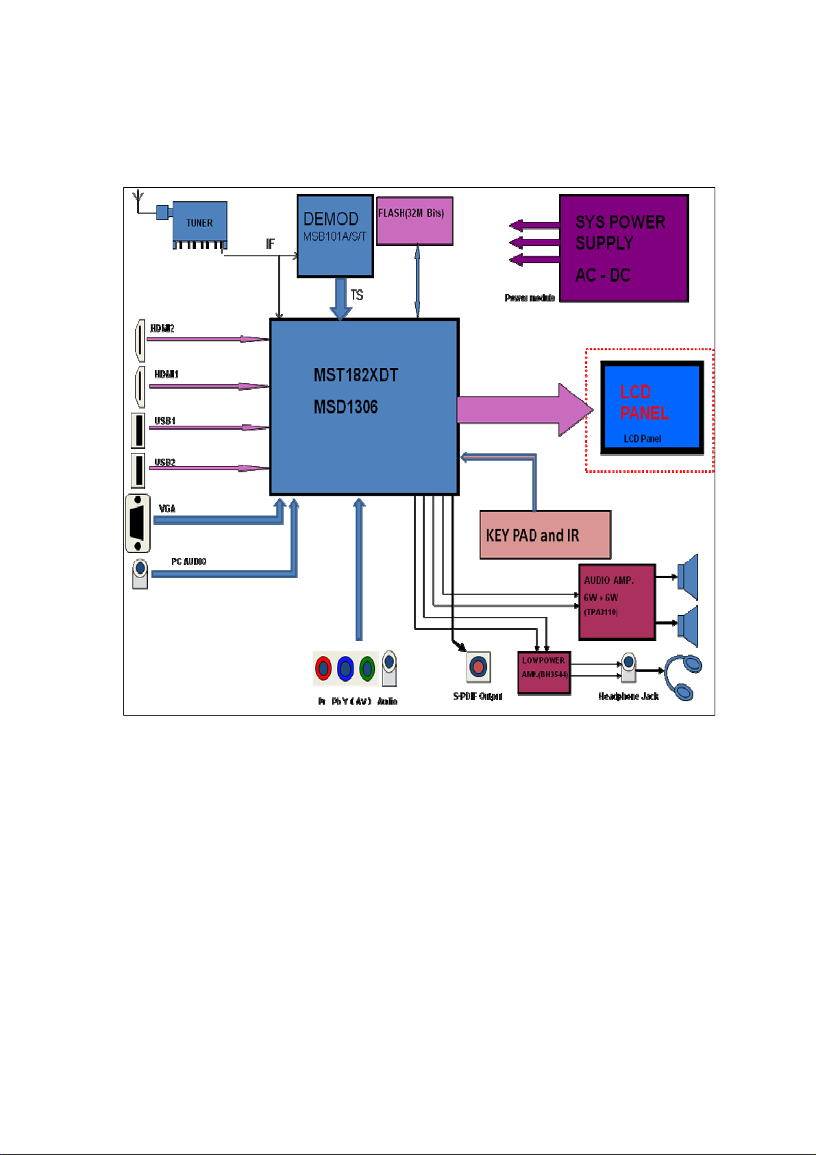
8M47E Block Diagram:
Page 13

List of key part:
No. Name Position Type P/N
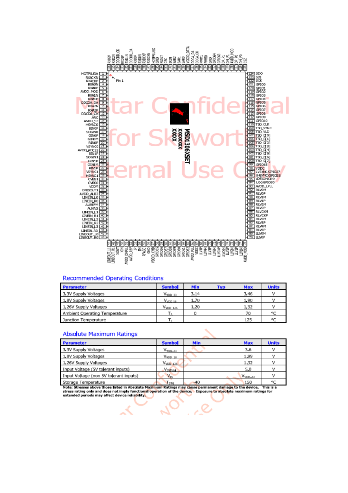
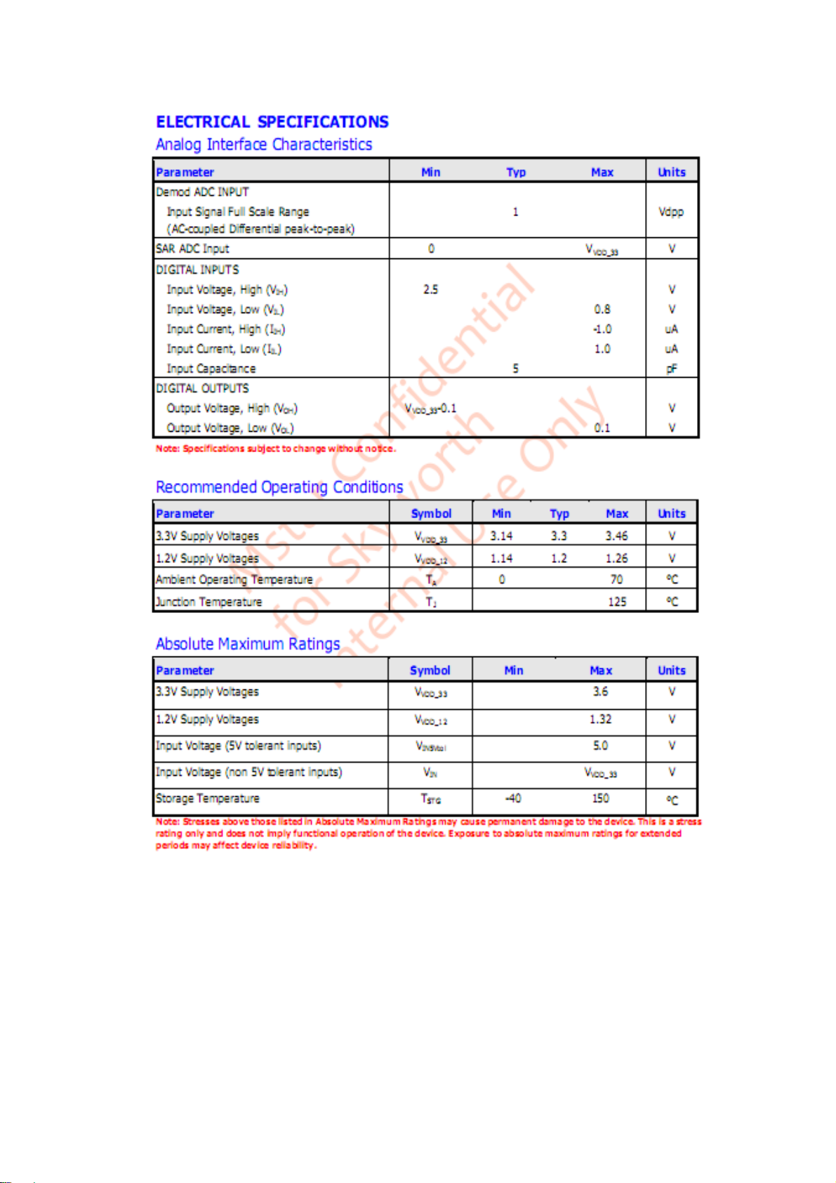
1 U14 MSD1306XSET 475C-M13060-1560
2 U16 MSB101T 475C-M10102-0480
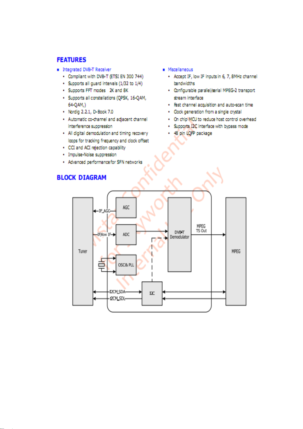
3 U3 TDA18274HD 4706-T18270-0480
4 U7 MP1495 476A-M14950-0080
5 U2 TPA3110D2 4722-T31100-0280
6 U100 GD25Q32B 47F2-G25320-0080
7 U13 BH3544 4740-B35440-0080
IC
8 U30
G5250F2T1 474R-G52500-0050
9 U31
10 U53 SY8086 47EC-S80860-0050
11 U10 ME9435A 47D9-M94350-0080
12 U12
AS1117L-3.3 47B6-A11170-03
13 U8
14
U4 AS1117L-1.8 47B6-A11172-03
Page 14
MSD1306XSET:
Page 15
Page 16
Page 17
Page 18
MSB101T:
Page 19
Page 20
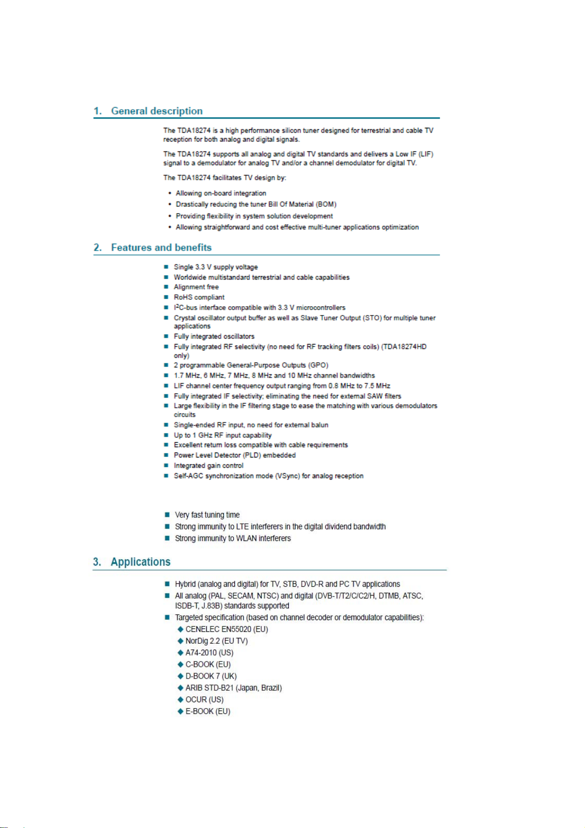
TDA18274HD:
Page 21

Page 22

MP1495:
Page 23

Page 24

TPA3110D2:
Page 25

Page 26

GD25Q32B:
Page 27

BH3544:
Page 28

G5250F2T1:
Page 29

SY8086:
Page 30

Page 31

ME9435A:
Page 32

AS1117L:
Page 33

5
4
3
2
1
C4
10uFC410uF
R39 1KR39 1K
1
CA29
CA29
100uF/16 V
100uF/16 V
1
Q4
Q4
AO3401A /NC
AO3401A /NC
C149
C149
0.1uF
0.1uF
R344 100R344 100
R32 1KR32 1K
Q23
Q23
3904
3904
2 3
L38 FBL38 FB
+5V_Standby
+3.3V_Stan dby
BRI_ADJ-PW M1
BRI_ADJ-PW M0
C82
C82
+
+
0.1uF
0.1uF
1
+5V_Standby
C72 1uFC72 1uF
R69
R69
2.2K
2.2K
2 3
+1.2V_VDDC
R48
R48
4.7K
4.7K
VBL_CTRL
R44
R44
10K/NC
10K/NC
VPANEL_IN
R40
R40
10K
10K
Q21
Q21
3904
3904
2 3
1
Q19
Q19
3904
3904
12VST_ON/OFF
R33 1 0KR33 10K
R341 4.7KR341 4.7K
L50 FBL50 FB
C83
C83
1uF
1uF
+5V_Normal
C97
C97
0.1UF
0.1UF
+5V_Standby
+1.2V_VDDM
VBL_CTRL
BRI_ADJ-PW M1
BRI_ADJ-PW M0
U10
U10
ME9435A
ME9435A
1
S
2
S
3
S
4
G
C80
C80
+3.3V_Stan dby
R25
R25
2.2K
2.2K
1
Q18
Q18
3904
3904
2 3
R343 2.2KR343 2.2K
1
Q26
Q26
3904
3904
2 3
5
D
6
D
7
D
8
D
33nF
33nF
R340 2.2KR340 2.2K
VCC-Panel
VPANEL_IN
R46
R46
2.2K
2.2K
Q5
ME2345Q5ME2345
PWR-ON/O FF
VCC-Panel
+5V_Standby
LDO
+5V_Standby
+5V_Normal
L22 FBL22 FB
22uF/16V
22uF/16V
NC/200R
NC/200R
+12V_NORMAL
CA53
CA53
AS1117L -3.3
AS1117L -3.3
R27
R27
1.2K
1.2K
R282KR28
R22
R22
R24
R24
0R/200R
0R/200R
L27 FBL27 FB
FB
L28FBL28
R67 4 70KR67 4 70K
C35 NC/0.1uFC35 NC/0.1uF
R68
R68
C25
C25
CA125
CA125
C23
C23
10uF/16v
10uF/16v
100K
100K
+
+
0.1uF/16v
0.1uF/16v
100uF/16 V
100uF/16 V
C29
C29
0.1uF
0.1uF
U53
U53
VCC4OUT
R93 10kR93 10k
C119
C119
C142
C142
+
+
1uF
1uF
0.1uF
0.1uF
1
EN
2
GND
4
U8
U8
ADJ
OUT
ADJ
OUT
IN
IN
320mA
321
+3.3V_Stan dby
C73
C73
C75
C75
C76
C76
2K
0.1uF
0.1uF
4
ADJ
OUT
ADJ
OUT
IN
IN
321
C17
C17
C16
C16
2.2uF
2.2uF
0.1uF
0.1uF
2.2uF
2.2uF
AS1117L -1.8
AS1117L -1.8
C18
C18
0.1uF
0.1uF
0.1uF
0.1uF
C21
C21
10uF
10uF
C77
C77
10uF
10uF
U4
U4
L7 0RL7 0R
C22
C22
10uF
10uF
R53
R53
100K
100K
R51
R51
10K
10K
SY8086
SY8086
130mA
+12V_1
AVDD_DDR+1.8V_DDR2
5V
0.4~0.6V
C32
C32
10nF
10nF
FB
2
6
7
1
3
5
U7
U7
IN
EN/SYNC
VCC
AAM
+5V_Normal
BST
SW
FB
GND
4
MP1495DJ-LF-Z
MP1495DJ-LF-Z
L44 3.3uHL44 3.3uH
AS1117L -3.3
AS1117L -3.3
R1972KR197
R64
R64
22R
22R
5
3
8
R159
R159
22K
22K
R157
R157
20K
20K
R72 33kR72 33k
C24
C24
0.1uF
0.1uF
C140
C140
10pF
10pF
2010-3-14
CA13
CA13
+
+
22uF/16V
22uF/16V
10uH/3A
10uH/3A
L11
L11
500mA
+1.2V_VDDC
C199
C199
0.1u
0.1u
R61
R61
56K_1%
56K_1%
R66
R66
R65
R65
10K_1%
10K_1%
4
U12
U12
ADJ
OUT
ADJ
OUT
IN
IN
320mA
321
R1881.2KR1881.2K
C116
C116
2K
0.1uF
0.1uF
+3.3V_Normal
C110
C110
C113
C113
C114
C114
10uF
10uF
0.1uF
0.1uF
2.2uF
2.2uF
H5NCH5
1
2
NC
+5V_Normal/
5V
C27
C27
C28
C28
NC/0.1uF
NC/0.1uF
NC/0
NC/0
+
+
CA126
CA126
0.1uF
220uF/16 V
220uF/16 V
0.1uF
DGND GND AGND GND_SIGNAL
M2NCM2
1
NC
H4NCH4
1
5
9
4
8
3
7
2
6
NC
H6NCH6
1
5
4
3
2
NC
M4NCM4
NC
1
M1NCM1
M3NCM3
NC
NC
1
1
H1NCH1
1
5
9
4
8
3
7
2
6
NC
H3NCH3
1
5
9
8
7
6
9
4
8
3
7
2
6
NC
8M27 SCHEMATIC DIAGRAM (1)
TP2NCTP2
TP3NCTP3
NC
1
NC
1
THIS IS MAIN BOARD SCHEMATIC DIAGRAM,ONLY FOR REFERENCE.
SOME SPECIAL FUNCTIONS ARE OPTIONAL.IT IS SUBJECT TO CHANGE
WITHOUT PRIOR NOTICE.
+5V_Standby
CN2
CN2
D D
CON10:5400-92400 0-10
CON10:5400-92400 0-10
BL-ON/OFF
1
BL-ADJUST
2
3
STANDBY
4
5
6
7
8
9
10
+5V_Standby
+12V_NORMAL
STANDBY
4
U1
U1
ADJ
OUT
ADJ
R2
R10RR1
0R
+5V_Normal
R341KR34
1K
R49
R49
3904Q73904
PANEL_ON/OFF
R52
R52
47K
47K
R56 10KR56 10K
OUT
IN
IN
150mA
321
+1.2V_VDDM
NC/1.2KR2NC/1.2K
C3
C2
C1
0.1uFC30.1uF
0.1uFC20.1uF
2.2uFC12.2uF
R421KR42
1K
R70NCR70
Q28
Q28
NC
3904
3904
2 3
Q7
1
2 3
R38 4.7KR38 4.7K
FB2 NC/0RFB2 NC/0R
FB1 0RFB1 0R
R31
R31
4.7K
4.7K
R45
R45
4.7K
4.7K
R43 1KR43 1K
FB/NC
FB/NC
L39
L39
C98
C98
0.1uF
0.1uF
AS1117L -1.2
AS1117L -1.2
+5V_Normal
C C
BL-ON/OFF
R35 0RR35 0R
BL-ADJUST
C88
C88
NC/12K
NC/12K
NC/2.2uF
NC/2.2uF
+5V_Normal/
B B
2
+5V_Normal/
A A
+12V_NORMAL
+5V_Normal
PANEL_ON/OFF
+5V_Normal/
12VST_ON/OFF
5
4
3
2
1
Page 34

5
4
3
2
1
SERIAL FLASH
RESET CIRCUIT
+5V_Standby
3
1
C111
C111
2.2uF
2.2uF
D100
D100
BAV99
BAV99
R102 100KR102 100K
C164
C164
220pF
220pF
C166
C166
220pF
220pF
C167
C167
220pF
220pF
C168
C168
220pF
220pF
2
1
RGB2-HDTV_BIN
RGB2-HDTV_SOGIN
RGB2-HDTV_GIN
RGB2-HDTV_RIN
AV_AUOUTL3AV-AUOUTL3
AMP_AUOUTR0
AMP_AUOUTL0
C101
C101
2.2uF
2.2uF
Q101
Q101
3906
3906
3 2
R103 1KR103 1K
R105
R105
22K
22K
HDMI_HP1
HDMI_HP1
HDMI1-CLKN
HDMI1-CLKN
HDMI1-CLKP
HDMI1-CLKP
HDMI1-RX0N
HDMI1-RX0N
HDMI1-RX0P
HDMI1-RX0P
HDMI1-RX1N
HDMI1-RX1N
HDMI1-RX1P
HDMI1-RX1P
HDMI1-SDA DDCDA_DA
HDMI1-SDA
HDMI1-RX2N
HDMI1-RX2N
HDMI1-RX2P
HDMI1-RX2P
HDMI1-SCL DDCDA_CK
HDMI1-SCL
ARC HDMI 1-ARC
ARC
VGA_HS
VGA_HS
RGB0_Pb+
RGB0_Pb+
RGB0_Y-SOG
RGB0_Y-SOG
RGB0_Y+
RGB0_Y+
RGB0_Pr+
VGA_VS
RGB2-HDTV_BIN
RGB2-HDTV_SOGIN
RGB2-HDTV_GIN
AVDD_33
TP5TP5
AV-CVBS0P CVBS0P
AV-CVBS0P
AV_AULin0 AUL0
AV_AULin0
AV_AURin0
VGA-AULin0 AUL1
VGA-AULin0
VGA-AURin0
VGA-AURin0
AV_AUOUTL3
R121
R121
200K
200K
AV_AUOUTR3AV-AUOUTR3
AV_AUOUTR3
R126
R126
200K
200K
AMP_AUOUTR0
R127
R127
200K
200K
AMP_AUOUTL0
R133
R133
200K
200K
R148 68RR148 68R
RGB0_Pr+
VGA_VS
R149 68RR149 68R
HSYNC1
1
R150 68RR150 68R
System-RST
C112
C112
1nF
1nF
R147 0RR147 0R
C195 47nFC195 47nF
C184 1nFC184 1nF
C150 47nFC150 47nF
C151 47nFC151 47nF
C194 47nFC194 47nF
C152 47nFC152 47nF
C189 1nFC189 1nF
C196 47nFC196 47nF
C185 47nFC185 47nF
C154 47nFC154 47nF
R827 NC/0RR827 NC/0R
R828 0RR828 0R
C159 47nFC159 47nF
C155 47nFC155 47nF
C198 2.2uFC198 2.2uF
C197 2.2uFC197 2.2uF
C200 2.2uFC200 2.2uF
C201 2.2uFC201 2.2uF
BIN0
SOGIN0
GIN0P
GIN0M
RIN0
BIN2
SOGIN2
GIN2P
GIN2M
RIN2
VCOM0
AVDD_33
VDDC
AVDD_ADC
AUR0AV_AURin0
AUR1
HDMI_HP1
HDMI1-CLKN
HDMI1-CLKP
HDMI1-RX0N
HDMI1-RX0P
HDMI1-RX1N
HDMI1-RX1P
DDCDA_DA
HDMI1-RX2N
HDMI1-RX2P
DDCDA_CK
HDMI1-ARC
VGA_HS
BIN0
SOGIN0
GIN0P
GIN0M
RIN0
VGA_VS
BIN2
SOGIN2
GIN2P
GIN2M
RIN2
SCART_HS
CVBS0PCVBS0PCVBS0PCVBS0PCVBS0PCVBS0P
VCOM0
1
TP6TP6
AU33
AUL0
AUR0
AUVRM
AUVAG
AUL1
AUR1
AV-AUOUTL3
AV-AUOUTR3
1
2
3
4
5
6
7
8
9
10
11
12
13
14
15
16
17
18
19
20
21
22
23
24
25
26
27
28
29
30
31
32
33
34
35
36
37
38
39
40
41
42
43
44
45
46
MST6M182XDT_NEW
MST6M182XDT_NEW
R1011MR101
D D
C C
B B
1M
AMP-AUOUTR0
AMP-AUOUTL0
System XTAL
C157
C157
33pF
+5V_Standby
R117
R117
R118
R118
4.7K
4.7K
4.7K
4.7K
R184 68RR184 68R
UART_RX
UART_TX
R185 68RR185 68R
A A
PWM1
CHIP_CONFIG
R181
R181
4.7K
4.7K
R0402
R0402
100R
100R
R187
R187
5
BRI_ADJ-PWM0PWM1
UART-RX
UART-TX
R183
R183
4.7K
4.7K
R0402
R0402
SYS_SDASYS_SDA
SYS_SCLSYS_SCL
USB_ON
CN3
CN3
1
2
3
4
5
CON4_2.5
CON4_2.5
33pF
R1201MR120
Y100
Y100
3
24MHZ
24MHZ
1 2
C163
C163
1M
33pF
33pF
R131 0RR131 0R
Audio
C160
C160
0.1uF
0.1uF
L103FBL103
FB
4
HDMI0-SCL
HDMI0-RX2P
HDMI0-RX2N
HDMI0-SCLDDCDD_CK
HDMI0-RX2N
HDMI0-RX2P
HDMI0-RX1P
DDCDD_CK
HDMI0-RX1P
HDMI0-RX2P
HDMI0-RX2N
156
155
154
153
157
158
159
160
E-PAD
MASK0
MASK1
RX2P_D
RX2N_D
Test_EPAD
DDCDD_CK
HOTPLUGA
RXCN_A
RXCP_A
RX0N_A
RX0P_A
AVDD_MOD
RX1N_A
RX1P_A
DDCDA_DA
RX2N_A
RX2P_A
DDCDA_CK
ARC0
AVDD1P2_DVI_A
HSYNC0
BIN0P
SOGIN0
GIN0P
GIN0M
RIN0P
VSYNC0
AVDD3P3_ADC/AVDD2P5_ADC
BIN1P
SOGIN1
GIN1P
GIN1M
RIN1P
VSYNC1
HSYNC1/AVDD303_ADC
CVBS1
CVBS0
VCOM0
CVBS_OUT1
AVDD_AU33
LINEIN_L0
LINEIN_R0
AUREFM
VAG
LINEIN_L1
LINEIN_R1
LINEIN_L2
LINEIN_R2
LINEIN_L3
LINEIN_R3
LINEOUT_L0
LINEOUT_R0
LINEOUT_L1
LINEOUT_R1
XTAL_OUT49IFAGC55VDDIO_CMD57GPIO5558VIFM
50
47
48
XTALI
XTALO
AMP-AUOUTR0
AMP-AUOUTL0
XTALI
XTALO
AUVRM
AUVAG
C162
C162
10uF
10uF
HDMI0-RX1P
HDMI_HP0
HDMI0-SDADDCDD_DA
HDMI0-CLKP
HDMI0-CLKN
HDMI_HP0
HDMI0-RX0N
HDMI0-RX0P
HDMI0-RX1N
HDMI0-RX0N
HDMI0-CLKP
HDMI0-CLKN
HDMI0-RX1N
HDMI_HP0
DDCDD_DA
HDMI0-RX0P
System-RST
GND-EFUSE
144
152
151
150
149
148
147
146
145
RX1P_D
RX0P_D
RX1N_D
RX0N_D
RXCP_D
RXCN_D
DDCDD_DA
HOTPLUGD
GND_EFUSE
AVDD3P3_DADC
AVDD3P3_DMPLL51XTAL_IN
GND
VIFP
52
56
54
53
VIFP
VIFMVIFMVIFMVIFMVIFMVIFMVIFMVIFMVIFMVIFMVIFMVIFMVIFMVIFMVIFMVIFMVIFMVIFMVIFMVIFMVIFMVIFMVIFMVIFMVIFMVIFMVIFMVIFMVIFMVIFMVIFMVIFMVIFMVIFMVIFMVIFMVIFMVIFMVIFMVIFMVIFMVIFMVIFMVIFMVIFMVIFMVIFMVIFMVIFMVIFMVIFMVIFMVIFMVIFMVIFMVIFMVIFMVIFMVIFMVIFMVIFMVIFMVIFMVIFMVIFMVIFMVIFMVIFMVIFMVIFMVIFMVIFMVIFMVIFMVIFMVIFMVIFMVIFMVIFMVIFMVIFMVIFMVIFMVIFMVIFMVIFMVIFMVIFMVIFMVIFMVIFMVIFMVIFMVIFMVIFMVIFMVIFMVIFMVIFMVIFMVIFMVIFMVIFMVIFMVIFMVIFMVIFMVIFMVIFMVIFMVIFMVIFMVIFMVIFMVIFMVIFMVIFMVIFMVIFMVIFMVIFMVIFMVIFMVIFMVIFMVIFMVIFMVIFMVIFMVIFMVIFMVIFMVIFMVIFMVIFMVIFMVIFMVIFMVIFMVIFMVIFMVIFMVIFMVIFMVIFMVIFMVIFMVIFMVIFMVIFMVIFMVIFMVIFMVIFMVIFMVIFMVIFMVIFMVIFMVIFMVIFMVIFMVIFMVIFMVIFMVIFMVIFMVIFMVIFMVIFMVIFMVIFMVIFMVIFMVIFMVIFMVIFMVIFMVIFMVIFMVIFMVIFMVIFMVIFMVIFMVIFMVIFMVIFMVIFMVIFMVIFMVIFMVIFMVIFMVIFMVIFMVIFMVIFMVIFMVIFMVIFMVIFMVIFMVIFMVIFMVIFMVIFMVIFMVIFMVIFMVIFMVIFMVIFMVIFMVIFMVIFMVIFMVIFMVIFMVIFMVIFMVIFMVIFMVIFMVIFMVIFMVIFMVIFMVIFMVIFMVIFMVIFMVIFMVIFMVIFMVIFMVIFMVIFMVIFMVIFMVIFMVIFMVIFMVIFMVIFMVIFMVIFMVIFMVIFMVIFMVIFMVIFMVIFMVIFMVIFMVIFM
AGCAGCAGCAGCAGCAGCAGCAGCAGCAGCAGCAGCAGCAGCAGCAGCAGCAGCAGCAGCAGCAGCAGCAGCAGCAGCAGCAGCAGCAGCAGCAGCAGCAGCAGCAGCAGCAGCAGCAGCAGCAGCAGCAGCAGCAGCAGCAGCAGCAGCAGCAGCAGCAGCAGCAGCAGCAGCAGCAGCAGCAGCAGCAGCAGCAGCAGCAGCAGCAGCAGCAGCAGCAGCAGCAGCAGCAGCAGCAGCAGCAGCAGCAGCAGCAGCAGCAGCAGCAGCAGCAGCAGCAGCAGCAGCAGCAGCAGCAGCAGCAGCAGCAGCAGCAGCAGCAGCAGCAGCAGCAGCAGCAGCAGCAGCAGCAGCAGCAGCAGCAGCAGCAGCAGCAGCAGCAGCAGCAGCAGCAGCAGCAGCAGCAGCAGCAGCAGCAGCAGCAGCAGCAGCAGCAGCAGCAGCAGCAGCAGCAGCAGCAGCAGCAGCAGCAGCAGCAGCAGCAGCAGCAGCAGCAGCAGCAGCAGCAGCAGCAGCAGCAGCAGCAGCAGCAGCAGCAGCAGCAGCAGCAGCAGCAGCAGCAGCAGCAGCAGCAGCAGCAGCAGCAGCAGCAGCAGCAGCAGCAGCAGCAGCAGCAGCAGCAGCAGCAGCAGCAGCAGCAGCAGCAGCAGCAGCAGCAGCAGCAGCAGCAGCAGCAGCAGCAGCAGCAGCAGCAGCAGCAGCAGCAGCAGCAGCAGCAGCAGCAGCAGCAGCAGCAGCAGCAGCAGCAGCAGCAGCAGCAGCAGCAGCAGCAGCAGCAGCAGCAGCAGCAGCAGCAGCAGCAGCAGCAGCAGCAGCAGCAGCAGCAGCAGCAGCAGCAGCAGCAGCAGCAGCAGCAGCAGCAGCAGCAGCAGCAGCAGCAGCAGCAGCAGCAGCAGCAGCAGCAGCAGCAGCAGCAGCAGCAGCAGCAGCAGCAGCAGCAGCAGCAGCAGCAGCAGCAGCAGCAGCAGCAGCAGCAGCAGCAGCAGCAGCAGCAGCAGCAGCAGCAGCAGCAGCAGCAGCAGCAGCAGCAGCAGCAGCAGCAGCAGCAGCAGCAGCAGCAGCAGCAGCAGCAGCAGCAGCAGCAGCAGCAGCAGCAGCAGCAGCAGCAGCAGCAGCAGCAGCAGCAGCAGCAGCAGCAGCAGCAGCAGCAGCAGCAGCAGCAGCAGCAGCAGCAGCAGCAGCAGCAGCAGCAGCAGCAGCAGCAGCAGCAGCAGCAGCAGCAGCAGCAGCAGCAGCAGCAGCAGCAGCAGCAGCAGCAGCAGCAGCAGCAGCAGCAGCAGCAGCAGCAGCAGCAGCAGCAGCAGCAGCAGCAGCAGCAGCAGCAGCAGCAGCAGCAGCAGCAGCAGCAGCAGCAGCAGCAGCAGCAGCAGCAGCAGCAGCAGCAGCAGCAGCAGCAGCAGCAGCAGCAGCAGCAGCAGCAGCAGCAGCAGCAGCAGCAGCAGCAGCAGCAGCAGCAGCAGCAGCAGCAGCAGCAGCAGCAGCAGCAGCAGCAGCAGCAGCAGCAGCAGCAGCAGCAGCAGCAGCAGCAGCAGCAGCAGCAGCAGCAGCAGCAGCAGCAGCAGCAGCAGCAGCAGCAGCAGCAGCAGCAGCAGCAGCAGCAGCAGCAGCAGCAGCAGCAGCAGCAGCAGCAGCAGCAGCAGCAGCAGCAGCAGCAGCAGCAGCAGCAGCAGCAGCAGCAGCAGCAGCAGCAGCAGCAGCAGCAGCAGCAGCAGCAGCAGCAGCAGCAGCAGCAGCAGCAGCAGCAGCAGCAGCAGCAGCAGCAGCAGCAGCAGCAGCAGCAGCAGCAGCAGCAGCAGCAGCAGCAGCAGCAGCAGCAGCAGCAGCAGCAGCAGCAGCAGCAGCAGCAGCAGCAGCAGCAGCAGCAGCAGCAGCAGCAGCAGCAGCAGCAGCAGCAGCAGCAGCAGCAGCAGCAGCAGCAGCAGCAGCAGCAGCAGCAGCAGCAGCAGCAGCAGCAGCAGCAGCAGCAGCAGCAGCAGCAGCAGCAGCAGCAGCAGCAGCAGCAGCAGCAGCAGCAGCAGCAGCAGCAGCAGCAGCAGCAGCAGCAGCAGCAGCAGCAGCAGCAGCAGCAGCAGCAGCAGCAGCAGCAGCAGCAGCAGCAGCAGCAGCAGCAGCAGCAGCAGCAGCAGCAGCAGCAGCAGCAGCAGCAGCAGCAGCAGCAGCAGCAGCAGCAGCAGCAGCAGCAGCAGCAGCAGCAGCAGCAGCAGCAGCAGCAGCAGCAGCAGCAGCAGCAGCAGCAGCAGCAGCAGCAGCAGCAGCAGCAGCAGCAGCAGCAGCAGCAGCAGCAGCAGCAGCAGCAGCAGCAGCAGCAGCAGCAGCAGCAGCAGCAGCAGCAGCAGCAGCAGCAGCAGCAGCAGCAGCAGCAGCAGCAGCAGCAGCAGCAGCAGCAGCAGCAGCAGCAGCAGCAGCAGCAGCAGCAGCAGCAGCAGCAGCAGCAGCAGCAGCAGCAGCAGCAGCAGCAGCAGCAGCAGCAGCAGCAGCAGCAGCAGCAGCAGCAGCAGCAGCAGCAGCAGCAGCAGCAGCAGCAGCAGCAGCAGCAGCAGCAGCAGCAGCAGCAGCAGCAGCAGCAGCAGCAGCAGCAGCAGCAGCAGCAGCAGCAGCAGCAGCAGCAGCAGCAGCAGCAGCAGCAGCAGCAGCAGCAGCAGCAGCAGCAGCAGCAGCAGCAGCAGCAGCAGCAGCAGCAGCAGCAGCAGCAGCAGCAGCAGCAGCAGCAGCAGCAGCAGCAGCAGCAGCAGCAGCAGCAGCAGCAGCAGCAGCAGCAGCAGCAGCAGCAGCAGCAGCAGCAGCAGCAGCAGCAGCAGCAGCAGCAGCAGCAGCAGCAGCAGCAGCAGCAGCAGCAGCAGCAGCAGCAGCAGCAGCAGCAGCAGCAGCAGCAGCAGCAGCAGCAGCAGCAGCAGCAGCAGCAGCAGCAGCAGCAGCAGCAGCAGCAGCAGCAGCAGCAGCAGCAGCAGCAGCAGCAGCAGCAGCAGCAGCAGCAGCAGCAGCAGCAGCAGCAGCAGCAGCAGCAGCAGCAGCAGCAGCAGCAGCAGCAGCAGCAGCAGCAGCAGCAGCAGCAGCAGCAGCAGCAGCAGCAGCAGCAGCAGCAGCAGCAGCAGCAGCAGCAGCAGCAGCAGCAGCAGCAGCAGCAGCAGCAGCAGCAGCAGCAGCAGCAGCAGCAGCAGCAGCAGCAGCAGCAGCAGCAGCAGCAGCAGCAGCAGCAGCAGCAGCAGCAGCAGCAGCAGCAGCAGCAGCAGCAGCAGCAGCAGCAGCAGCAGCAGCAGCAGCAGCAGCAGCAGCAGCAGCAGCAGCAGCAGCAGCAGCAGCAGCAGCAGCAGCAGCAGCAGCAGCAGCAGCAGCAGCAGCAGCAGCAGCAGCAGCAGCAGCAGCAGCAGCAGCAGCAGCAGCAGCAGCAGCAGCAGCAGCAGCAGCAGCAGCAGCAGCAGCAGCAGCAGCAGCAGCAGCAGCAGCAGCAGCAGCAGCAGCAGCAGCAGCAGCAGCAGCAGCAGCAGCAGCAGCAGCAGCAGCAGCAGCAGCAGCAGCAGCAGCAGCAGCAGCAGCAGCAGCAGCAGCAGCAGCAGCAGCAGCAGCAGCAGCAGCAGCAGCAGCAGCAGCAGCAGCAGCAGCAGCAGCAGCAGCAGCAGCAGCAGCAGCAGCAGCAGCAGCAGCAGCAGCAGCAGCAGCAGCAGCAGCAGCAGCAGCAGCAGCAGCAGCAGCAGCAGCAGCAGCAGCAGCAGCAGCAGCAGCAGCAGCAGCAGCAGCAGCAGCAGCAGCAGCAGCAGCAGCAGCAGCAGCAGCAGCAGCAGCAGCAGCAGCAGCAGCAGCAGCAGCAGCAGCAGCAGCAGCAGCAGCAGCAGCAGCAGCAGCAGCAGCAGCAGCAGCAGCAGCAGCAGCAGCAGCAGCAGCAGCAGCAGCAGCAGCAGCAGCAGCAGCAGCAGCAGCAGCAGCAGCAGCAGCAGCAGCAGCAGCAGCAGCAGCAGCAGCAGCAGCAGCAGCAGCAGCAGCAGCAGCAGCAGCAGCAGCAGCAGCAGCAGCAGCAGCAGCAGCAGCAGCAGCAGCAGCAGCAGCAGCAGCAGCAGCAGCAGCAGCAGCAGCAGCAGCAGCAGCAGCAGCAGCAGCAGCAGCAGCAGCAGCAGCAGCAGCAGCAGCAGCAGCAGCAGCAGCAGCAGCAGCAGCAGCAGCAGCAGCAGCAGCAGCAGCAGCAGCAGCAGCAGCAGCAGCAGCAGCAGCAGCAGCAGCAGCAGCAGCAGCAGCAGCAGCAGCAGCAGCAGCAGCAGCAGCAGCAGCAGCAGCAGCAGCAGCAGCAGCAGCAGCAGCAGCAGCAGCAGCAGCAGCAGCAGCAGCAGCAGCAGCAGCAGCAGCAGCAGCAGCAGCAGCAGCAGCAGCAGCAGCAGCAGCAGCAGCAGCAGCAGCAGCAGCAGCAGCAGCAGCAGCAGCAGCAGCAGCAGCAGCAGCAGCAGCAGCAGCAGCAGCAGCAGCAGCAGCAGCAGCAGCAGCAGCAGCAGCAGCAGCAGCAGCAGCAGCAGCAGCAGCAGCAGCAGCAGCAGCAGCAGCAGCAGCAGCAGCAGCAGCAGCAGCAGCAGCAGCAGCAGCAGCAGCAGCAGCAGCAGCAGCAGCAGCAGCAGCAGCAGCAGCAGCAGCAGCAGCAGCAGCAGCAGCAGCAGCAGCAGCAGCAGCAGCAGCAGCAGCAGCAGCAGCAGCAGCAGCAGCAGCAGCAGCAGCAGCAGCAGCAGCAGCAGCAGCAGCAGCAGCAGCAGCAGCAGCAGCAGCAGCAGCAGCAGCAGCAGCAGCAGCAGCAGCAGCAGCAGCAGCAGCAGCAGCAGCAGCAGCAGCAGCAGCAGCAGCAGCAGCAGCAGCAGCAGCAGCAGCAGCAGCAGCAGCAGCAGCAGCAGCAGCAGCAGCAGCAGCAGCAGCAGCAGCAGCAGCAGCAGCAGCAGCAGCAGCAGCAGCAGCAGCAGCAGCAGCAGCAGCAGCAGCAGCAGCAGCAGCAGCAGCAGCAGCAGCAGCAGCAGCAGCAGCAGCAGCAGCAGCAGCAGCAGCAGCAGCAGCAGCAGCAGCAGCAGCAGCAGCAGCAGCAGCAGCAGCAGCAGCAGCAGCAGCAGCAGCAGCAGCAGCAGCAGCAGCAGCAGCAGCAGCAGCAGCAGCAGCAGCAGCAGCAGCAGCAGCAGCAGCAGCAGCAGCAGCAGCAGCAGCAGCAGCAGCAGCAGCAGCAGCAGCAGCAGCAGCAGCAGCAGCAGCAGCAGCAGCAGCAGCAGCAGCAGCAGCAGCAGCAGCAGCAGCAGCAGCAGCAGCAGCAGCAGCAGCAGCAGCAGCAGCAGCAGCAGCAGCAGCAGCAGCAGCAGCAGCAGCAGCAGCAGCAGCAGCAGCAGCAGCAGCAGCAGCAGCAGCAGCAGCAGCAGCAGCAGCAGCAGCAGCAGCAGCAGCAGCAGCAGCAGCAGCAGCAGCAGCAGCAGCAGCAGCAGCAGCAGCAGCAGCAGCAGCAGCAGCAGCAGCAGCAGCAGCAGCAGCAGCAGCAGCAGCAGCAGCAGCAGCAGCAGCAGCAGCAGCAGCAGCAGCAGCAGCAGCAGCAGCAGCAGCAGCAGCAGCAGCAGCAGCAGCAGCAGCAGCAGCAGCAGCAGCAGCAGCAGCAGCAGCAGCAGCAGCAGCAGCAGCAGCAGCAGCAGCAGCAGCAGCAGCAGCAGCAGCAGCAGCAGCAGCAGCAGCAGCAGCAGCAGCAGCAGCAGCAGCAGCAGCAGCAGCAGCAGCAGCAGCAGCAGCAGCAGCAGCAGCAGCAGCAGCAGCAGCAGCAGCAGCAGCAGCAGCAGCAGCAGCAGCAGCAGCAGCAGCAGCAGCAGCAGCAGCAGCAGCAGCAGCAGCAGCAGCAGCAGCAGCAGCAGCAGCAGCAGCAGCAGCAGCAGCAGCAGCAGCAGCAGCAGCAGCAGCAGCAGCAGCAGCAGCAGCAGCAGCAGCAGCAGCAGCAGCAGCAGCAGCAGCAGCAGCAGCAGCAGCAGCAGCAGCAGCAGCAGCAGCAGCAGCAGCAGCAGCAGCAGCAGCAGCAGCAGCAGCAGCAGCAGCAGCAGCAGCAGCAGCAGCAGCAGCAGCAGCAGCAGCAGCAGCAGCAGCAGCAGCAGCAGCAGCAGCAGCAGCAGCAGCAGCAGCAGCAGCAGCAGCAGCAGCAGCAGCAGCAGCAGC
IF-AGC-SEL
AVDD_DDR
AVDD_DADC
AVDD_DMPLL
SYS_SCL
R137
R137
100R
100R
HDMI-CEC
HDMI-CEC
IRIN
HDMI-CEC
143
142
CEC
RESET
U100
U100
GPIO5659GPIO5760GPIO5962GPIO60
61
AMP-MUTE
SYS_SDA
R139
R139
100R
100R
VIFP
VIFM
BRI_ADJ-PWM0
PWR-ON/OFF
SPI_WP0N
AVDD_DDR
VBL_CTRL
KEY0-SAR1
KEY0-SAR0
141
140
139
138
IRIN
SAR2
SAR1
SAR0
VDDIO_DATA
GPIO58
GPIO6164B_ODD[0]/LVA4+
63
65
MUTE_PHO
EAR-MUTE
AMP-MUTE
PANEL_ON/OFF
UART_RX
UART_TX
137
136
DDCA_DA
DDCA_CK
VDDC
AVDD_PLL66B_ODD[1]/LVA4-69GPIO62
67
VDDC
AVDD_33
R130 4.7KR130 4.7K
R132 4.7KR132 4.7K
VIFP
VIFM
BRI_ADJ-PWM0
PWM1
135
134
PWN1
68
RXE4-
RXE4+
AVDD_33
PWR-ON_OFF
SPI_WP0N
USB0_DP
128
129
127
133
132
131
130
PWM0
DP_P1
DM_P1
GPIO64
GPIO63
TESTPIN
AVDD_MOD
B_ODD[3]/LVA3-71B_ODD[4]/LVACLK+72B_ODD[5]/LVACLK-73B_ODD[6]/LVA2+74B_ODD[7]/LVA2-
B_ODD[2]/LVA3+
75
70
RXE3+
RXE3-
RXE2+
RXE2-
RXEC-RXEC-
RXE1+
RXEC+RXEC+
Tuner
+3.3V_Normal
IF-AGC-SEL
SYS_SCL
SYS_SDA
TAGC AGC
TAGC
C169
C169
22nF
22nF
3
USB0_D-
USB0_D+
SPI_CS0N
USB0_DM
126
125
DP_P0
DM_P0
SPI_CZ
POL/GPIO0
GST1/GPIO1
GCLK/GPIO2
MCLK/GPIO3
GST2/GPIO4
SOE/GPIO5
OPT_P/GPIO6
E/O/GPIO7
OPT_N/GPIO8
HCONV/GPIO9
DPM/GPIO10
TS0_SYNC
AVDD_LPLL
R_ODD[7]/LVB0-
R_ODD[6]/LVB0+
R_ODD[5]/LVB1-
R_ODD[4]/LVB1+
R_ODD[3]/LVB2-
R_ODD[2]/LVB2+
R_ODD[1]/LVBCLK-
R_ODD[0]/LVBCLK+
G_ODD[7]/LVB3-
G_ODD[6]/LVB3+
G_ODD[5]/LVB4-
G_ODD[4]/LVB4+
G_ODD[3]/LVA0-
G_ODD[2]/LVA0+
AVDD_MOD
G_ODD[0]/LVA1+76G_ODD[1]/LVA1-
78
77
RXE1-
AVDD_33
R135 0RR135 0R
SPI_DO
SPI_DI
SPI_CK
TS0_CLK
TS0_VLD
TS0_D0
TS0_D1
TS0_D2
TS0_D3
TS0_D4
TS0_D5
TS0_D6
TS0_D7
GPIO65
VDDC
LVSYNC
LHSYNC
LDE
LCK
IF-AGC-SEL 3
SYS_SCL
SYS_SDA
+3.3V_Normal
R134
R134
10K
10K
124
123
122
121
120
119
118
117
116
115
114
113
112
111
110
109
108
107
106
105
104
103
102
101
100
99
98
97
96
95
94
93
92
91
90
89
88
87
86
85
84
83
82
81
80
79
SPI_Flash-SDO
SPI_Flash-SDI
SPI_Flash-SCK
TS1_CLK
TS1_SYNC
TS1_VLD
TS1_D0
TS1_D1
TS1_D2
TS1_D3
TS1_D4
TS1_D5
TS1_D6
TS1_D7
R125 NC/33RR125 NC/33R
TCON0
TCON1
TCON2
TCON3
TCON4
TCON5
TCON6
TCON7
TCON8
TCON9
TCON10
LVSYNC
LHSYNC
LDE
LCK
RXO0RXO0+
RXO1RXO1+
RXO2RXO2+
RXOCRXOC+
RXO3RXO3+
RXO4RXO4+
RXE0RXE0+
LED
KEY0-SAR0
KEY0-SAR1
LED
R1251KR125
1K
TS_CLK
TS_SYNC
TS_VLD
TS_D0
TS_D1
TS_D2
TS_D3
TS_D4
TS_D5
TS_D6
TS_D7
Normal Power 1.2V
C102
C102
2.2uF
2.2uF
DDR power
AVDD_DDR
VDDC
AVDD_33
+3.3V_Standby
R123
R123
R122
R122
10K
10K
10K
10K
KEY0-in
R128100 R128100
KEY1-in
R129100 R129100
C125
C125
C124
C124
0.1uF
0.1uF
0.1uF
0.1uF
KEY0-in
KEY1-in
IR-in
VD101NCVD101
VD103NCVD103
VD102NCVD102
NC
NC
NC
1 2
1 2
+5V_Standby
R18
R18
10K
10K
1
LED1
LED1
R211KR21
1K
R
R
R50
R50
750
750
Q10
Q10
3904
3904
G
G
2 3
R58
R58
750
750
+5V_Standby
R541KR54
R551KR55
1K
1K
Q11
Q11
1
3904
3904
2 3
2
VDDC+1.2V_VDDC
C104
C104
C103
C103
0.1uF
0.1uF
0.1uF
0.1uF
L104 FBL104 FB
C123
C123
4.7uF
4.7uF
KEY1-in
KEY0-in
AU33
C138
C138
0.1uF
0.1uF
+3.3V_Standby
L105 FOR Other
+3.3V_Standby+3.3V_Standby
IR2
IR2
NC/IR RECEIVER D IP
NC/IR RECEIVER D IP
C122
C122
0.1uF
0.1uF
1 2
VBL_CTRLMUTE_PHO
HDMI0-CLKP
HDMI0-RX0N
HDMI0-RX1N
HDMI0-CLKN
HDMI0-RX0P
HDMI0-SDA
+3.3V_Standby
R111
R111
4.7K
4.7K
R1131K R1131K
C146
C146
0.1uF
0.1uF
L107 FBL107 FB
L105 NC/FBL105 NC/FB
L111 FBL111 FB
HDMI1_5V HDMI0_5V
LVSYNC
LHSYNC
RXO0RXO0+
5R1
5R1
RXO1RXO1+
RM3
RM3
RXO2-
5R1
5R1
RXO2+
RXOC-
RXO3-
RM4
RM4
RXO3+
5R1
5R1
RXO4RXO4+
RXE0RXE0+
RXE1RXE1+
RXE2-
RM6
RM6
RXE2+
5R1
5R1
RXECRXEC+
RXE3-
RM7
RM7
RXE3+
5R1
5R1
RXE4RXE4+
SW1
SW1
STB
STB
IR1
IR1
FLASH_CS0N
FLASH_WP0N
R115
R115
10K
10K
AVDD_ADC
L107
250mA
L105
C115
C115
0.1uF
0.1uF
Normal Power 3.3V
+3.3V_Standby
AVDD_DMPLL
C136
C136
C139
C139
0.1uF
0.1uF
2.2uF
2.2uF
Net to other page
R13 4.7KR13 4.7K
R14 4.7KR14 4.7K
LVSYNC
LHSYNC
LDE
LDE
LCK
LCK
1 8
R6_RXO0+R6_RXO0+R6_RXO0+
2
7
R5_RXO1-R5_RXO1-R5_RXO1-
3
6
R4_RXO1+R4_RXO1+R4_RXO1+
4 5
1 8
2
7
R1_RXOC-R1_RXOC-R1_RXOC-
3
6
4 5
1 8
G6_RXO3+G6_RXO3+G6_RXO3+
2
7
3
6
G4_RXO4+G4_RXO4+G4_RXO4+G4_RXO4+
4 5
G3_RXE0-G3_RXE0-G3_RXE0-
1 8
G2_RXE0+G2_RXE 0+G2_RXE0+
2
7
G1_RXE1-G1_RXE1-G1_RXE1-
3
6
G0_RXE1+G0_RXE 1+G0_RXE1+G0_RXE1+
4 5
B7_RXE2-B7_RXE2-B7_RXE2-B7_RXE2-
1 8
B6_RXE2+B6_RXE2+B6_RXE2+B6_RXE2+
2
7
B5_RXEC-B5_RXEC-B5_RXEC-
3
6
B4_RXEC+B4_RXEC+B4_RXEC+B4_RXEC+
4 5
B3_RXE3-B3_RXE3-B3_RXE3-
1 8
B2_RXE3+B2_RXE3+B2_RXE3+
2
7
B1_RXE4-B1_RXE4-B1_RXE4-
3
6
B0_RXE4+B0_RXE4+B0_RXE4+
4 5
SW2
SW2
MENU
MENU
R907
R907
27k
27k
+5V_Standby
R3
100R3100
C5
4.7uFC54.7uF
SPI_CS0N
SPI_Flash-SDO
C105
C105
0.1uF
0.1uF
L107 FOR MST6M182XDT
+1.8V_DDR2
RM2
RM2
RM5
RM5
5R1
5R1
IR RECEIVER SMD
IR RECEIVER SMD
8M27 SCHEMATIC DIAGRAM (2)
THIS IS MAIN BOARD SCHEMATIC DIAGRAM,ONLY FOR REFERENCE.
SOME SPECIAL FUNCTIONS ARE OPTIONAL.IT IS SUBJECT TO CHANGE
WITHOUT PRIOR NOTICE.
U14
U14
1
CE#
2
SO
HOLD#
3
WP#
VSS4SI
EN25F32
EN25F32
L106 FOR MST6M182XDT
AVDD_33
C137
C137
0.1uF
0.1uF
R15
R15
R16
R16
12K
12K
12K
12K
R7_RXO0-R7_RXO0-R7_RXO0-
R3_RXO2-R3_RXO2-R3_RXO2R2_RXO2+R2_RXO2+R2_RXO2+
R0_RXOC+R0_RXOC+R0_RXOC+RXOC+
G7_RXO3-G7_RXO3-G7_RXO3-
G5_RXO4-G5_RXO4-G5_RXO4-
SW3V-SW3
V-
C127
C127
100pF
100pF
+3.3V_Standby
8
VDD
7
6
SCK
5
L106 FBL106 FB
+3.3V_Standby
L102 NC/FBL102 NC/FB
+1.8V_DDR2
L102 FOR Other
VDD33
C186
C186
C135
C135
0.1uF
0.1uF
0.1uF
0.1uF
TCON0TCON0
TCON0TCON0TCON0TCON0TCON0
TCON0
TCON1TCON1
TCON1TCON1TCON1TCON1TCON1
TCON1
TCON2
TCON2
TCON3
TCON3
TCON4
TCON4
TCON5
TCON5
TCON6
TCON6
TCON7
TCON7
TCON8
TCON8
TCON9
TCON9
TCON10
TCON10
R7_RXO0-
R7_RXO0-
R6_RXO0+
R6_RXO0+
R5_RXO1-
R5_RXO1-
R4_RXO1+
R4_RXO1+
R3_RXO2-
R3_RXO2-
R2_RXO2+
R2_RXO2+
R1_RXOC-
R1_RXOC-
R0_RXOC+
R0_RXOC+
G7_RXO3-
G7_RXO3-
G6_RXO3+
G6_RXO3+
G5_RXO4-
G5_RXO4-
G4_RXO4+
G4_RXO4+
G3_RXE0-
G3_RXE0-
G2_RXE0+
G2_RXE0+
G1_RXE1-
G1_RXE1-
G0_RXE1+
G0_RXE1+
B7_RXE2-
B7_RXE2-
B6_RXE2+
B6_RXE2+
B5_RXEC-
B5_RXEC-
B4_RXEC+
B4_RXEC+
B3_RXE3-
B3_RXE3-
B2_RXE3+
B2_RXE3+
B1_RXE4-
B1_RXE4-
B0_RXE4+
B0_RXE4+
SW4V+SW4
V+
R901
R901
3K3
3K3
+5V_Standby
R143
R143
10K
10K
R145 100R 145 100
1
C187
C187
0.1uF
0.1uF
L106
L102
SPI_Flash-SCK
SPI_Flash-SDI
AVDD_DADC
C188
C188
0.1uF
0.1uF
SW5P-SW5
P-
R902
R902
10K
10K
IRINIR-inIR-in
C126
C126
22pF
22pF
C148
C148
0.1uF
0.1uF
SW6P+SW6
P+
R903
R903
27K
27K
Page 35

5
4
3
2
1
YPbPr/CVBS IN
D D
P2 6AP2 6A
HD_Y
HD_Pb
C C
B B
HD_Pr
1
1
2
2
3
3
4
5
6
10
4
5
11
12
6
CVBS_IN
7
7
8
8
9
9
10
11
12
AV_L
AV_R
AV_L
D505NCD505
NC
AV_R AV_AURin0
D506NCD506
NC
CVBS_IN
D509NCD509
NC
1 2
HD_Y
HD_Pb
HD_Pr
D502NCD502
D503NCD503
NC
NC
1 2
1 2
1 2
D504NCD504
NC
1 2
R507 10KR507 10K
C89
C89
220pF/NC
220pF/NC
R512 10KR512 10K
C91
C91
220pF/NC
220pF/NC
75R
75R
R519
R519
R50875R R50875R
1 2
R50975R R50975R
R511
R511
12K
12K
R513
R513
12K
12K
R518 33RR518 33R
R502 33RR502 33R
R503
R503
33R
33R
R505 33RR505 33R
R506 33RR506 33R
R51075R R51075R
AV_AULin0
AV-CVBS0P
RGB2-HDTV_GIN
RGB2-HDTV_SOGIN
RGB2-HDTV_BIN
RGB2-HDTV_RIN
AV_AULin0
AV_AURin0
AV-CVBS0P
RGB2-HDTV_GIN
RGB2-HDTV_SOGIN
RGB2-HDTV_BIN
RGB2-HDTV_RIN
A A
8M27 SCHEMATIC DIAGRAM (3)
THIS IS MAIN BOARD SCHEMATIC DIAGRAM,ONLY FOR REFERENCE.
SOME SPECIAL FUNCTIONS ARE OPTIONAL.IT IS SUBJECT TO CHANGE
WITHOUT PRIOR NOTICE.
5
4
3
2
1
Page 36

5
4
3
2
1
VGA AUDIO INPUT
2
D D
4
3
VGA-Lin1
VGA-Rin1
VGA-Rin1
1
P12P12
VGA-Lin1VGA-Lin1VGA-Lin1
C C
TP1NCTP1
NC
1
B B
P7
15
14
13
12
11
5
10
4
9
3
8
2
7
1
6
16
17
VGAP7VGA
UART-RX0
VGA-Bin
VGA-Gin
VGA-Rin
R155 10RR155 10R
D95NCD95
D104NCD104
NC
NC
1 2
1 2
UART-RX
D105NCD105
NC
R15375R153
1 2
75
R28575R285
75
R13875R138
75
R166 10KR166 10K
DD19
DD19
ESD-0402
ESD-0402
R167 10KR167 10K
DD20
DD20
ESD-0402
ESD-0402
R95 33R95 33
R161 33R161 33
R203 0R203 0
R97 33R97 33
RGB0_Pb+
RGB0_Y+
RGB0_Y-SOG
RGB0_Pr+
R165
R165
12K
12K
R168
R168
12K
12K
RGB0_Pb+
RGB0_Y+
RGB0_Y-SOG
RGB0_Pr+
C79
C79
200p
200p
C78
C78
200p
200p
VGA-AURin0
VGA-AULin0 2
2
R156 10RR156 10R
D42NCD42
A A
NC
D44NCD44
NC
1 2
1 2
UART-TX
VGA-HS
VGA-VS
R284 100R284 100
R154 100R154 100
UART-TXVGA-SDA
UART-RXVGA-SCL
UART-TX
UART-RX
D45NCD45
NC
D41NCD41
NC
1 2
1 2
R217
R217
10K
10K
R229
R229
10K
10K
VGA_HS
VGA_VS
VGA_HS
VGA_VS
8M27 SCHEMATIC DIAGRAM (4)
THIS IS MAIN BOARD SCHEMATIC DIAGRAM,ONLY FOR REFERENCE.
SOME SPECIAL FUNCTIONS ARE OPTIONAL.IT IS SUBJECT TO CHANGE
WITHOUT PRIOR NOTICE.
5
4
3
2
1
Page 37

5
P10
P10
USB_A
USB_A
D D
5
6
C C
B B
USB_ON
1
1
5
2
2
3
3
4
4
6
+12V_NORMAL
USB1_D1-_in
USB1_D1+_in
L1FBL1
+3.3V_Standby
R17 10KR17 10K
R12
R12
47K
47K
1
+5V_USB1
FB
R281
R281
10K
10K
2 3
4
NC
Q25
Q25
3904
3904
D62NCD62
NC
1 2
D61NCD61
1 2
R11
R11
C128
C128
22uF
22uF
4.7K
4.7K
R60 5.1R60 5.1
R59 5.1R59 5.1
+12V_1
3
IN
5
EN
U209
U209
USB0_DUSB0_D+
BST
SW
GND
1
MP1470
MP1470
FB
3
USB0_DUSB0_D+
R74
R74
22R
NC/0
NC/0
22R
C106
C106
1uF
1uF
L43
L43
C156NCC156
6
2
R76
R76
10uH/3A
10uH/3A
NC
2
R73
R73
56K_1%
56K_1%
+5V_USB1
C120
C120
22uF
22uF
C100
C100
0.1uF
0.1uF
1
C6
22uFC622uF
4
R75
R75
75k
75k
R80
R80
10K_1%
10K_1%
A A
8M27 SCHEMATIC DIAGRAM (5)
THIS IS MAIN BOARD SCHEMATIC DIAGRAM,ONLY FOR REFERENCE.
SOME SPECIAL FUNCTIONS ARE OPTIONAL.IT IS SUBJECT TO CHANGE
WITHOUT PRIOR NOTICE.
5
4
3
2
1
Page 38

5
HDMI2
P11
P11
20
GND
21
D D
C C
GND
GND
GND
CEC/DDC GND
DDC SCL
DDC SDA
CEC
HPD
Dat2 shield
Dat1 shield
Dat0 shield
clk shield
DAT0+
DAT0-
DAT1+
DAT1-
DAT2+
DAT2-
ARC1
HDMI
HDMI
+5V
clk+
22
23
18
17
15
16
13
19
2
5
8
11
7
9
4
6
1
3
10
12
clk-
14
HDMI0-HPD
C701 1uFC701 1uF
CEC
ARC
HDMI0_5V
D122NCD122
NC
HDMI1_5V
4
HDMI0_5V
D116NCD116
NC
HDMI0-HPD
D121NCD121
NC
R7311KR731
1K
HDMI0-DDC-SCL HDMI0-SCL
HDMI0-DDC-SDA
Q702
Q702
3904
3904
2 3
R733 4.7KR733 4.7K
1
R737
R737
10K
10K
R736
R736
10K
10K
HDMI_HP0
HDMI0-RX0+
HDMI0-RX0HDMI0-RX1+
HDMI0-RX1HDMI0-RX2+
HDMI0-RX2HDMI0-RXC+
HDMI0-RXC-
3
R734
R734
R735 22RR735 22R
10K
10K
R732 22RR732 22R
HDMI0-SDA
HDMI0-RX2+
HDMI0-RX2-
HDMI0-RX1+
HDMI0-RX1-
HDMI0-RX0+
HDMI0-RX0-
HDMI0-RXC+
HDMI0-RXC-
2
R701 10RR701 10R
R702 10RR702 10R
R703 10RR703 10R
R704 10RR704 10R
R705 10RR705 10R
R706 10RR706 10R
R707 10RR707 10R
R708 10RR708 10R
R709 200RR709 200R
HDMI0-RX2P
HDMI0-RX2N
HDMI0-RX1P
HDMI0-RX1N
HDMI0-RX0P
HDMI0-RX0N
HDMI0-CLKP
HDMI0-CLKN
HDMI_HP0
HDMI0-SCL
HDMI0-SDA
ARC
HDMI-CECCEC
HDMI0-RX2P
HDMI0-RX2N
HDMI0-RX1P
HDMI0-RX1N
HDMI0-RX0P
HDMI0-RX0N
HDMI0-CLKP
HDMI0-CLKN
HDMI_HP0
HDMI0-SCL
HDMI0-SDA
ARC
HDMI-CEC
1
HDMI1
P13
P13
20
GND
21
GND
22
GND
23
GND
B B
CEC/DDC GND
Dat2 shield
Dat1 shield
Dat0 shield
A A
HDMI
HDMI
+5V
DDC SCL
DDC SDA
CEC
HPD
clk shield
DAT0+
DAT0-
DAT1+
DAT1-
DAT2+
DAT2-
clk+
clk-
ARC1
18
17
15
16
13
19
2
5
8
11
7
9
4
6
1
3
10
12
14
CEC
HDMI1-HPD
C700 1uFC700 1uF
D124NCD124
NC
ARC
D117NCD117
NC
HDMI1-HPD
D123NCD123
NC
HDMI1_5V
R7391KR739
1K
Q703
Q703
3904
3904
HDMI1-DDC-SCL
HDMI1-DDC-SDA
R741 4.7KR741 4.7K
1
2 3
R743
R743
R744
R744
10K
10K
10K
10K
HDMI1-RX0+
HDMI1-RX0HDMI1-RX1+
HDMI1-RX1HDMI1-RX2+
HDMI1-RX2HDMI1-RXC+
HDMI1-RXC-
R740
R740
10K
10K
HDMI_HP1
R742 22RR742 22R
R738 22RR738 22R
HDMI1-SCL
HDMI1-SDA
HDMI1-RX2+
HDMI1-RX2HDMI1-RX1+
HDMI1-RX1HDMI1-RX0+
HDMI1-RX0-
HDMI1-RXC+
HDMI1-RXC-
R716 10RR716 10R
R717 10RR717 10R
R718 10RR718 10R
R719 10RR719 10R
R720 10RR720 10R
R721 10RR721 10R
R722 10RR722 10R
R723 10RR723 10R
HDMI1-RX2P
HDMI1-RX2N
HDMI1-RX1P
HDMI1-RX1N
HDMI1-RX0P
HDMI1-RX0N
HDMI1-CLKP
HDMI1-CLKN
HDMI_HP1
HDMI1-SCL
HDMI1-SDA
ARC
HDMI1-RX2P
HDMI1-RX2N
HDMI1-RX1P
HDMI1-RX1N
HDMI1-RX0P
HDMI1-RX0N
HDMI1-CLKP
HDMI1-CLKN
HDMI_HP1
HDMI1-SCL
HDMI1-SDA
ARC
8M27 SCHEMATIC DIAGRAM (6)
THIS IS MAIN BOARD SCHEMATIC DIAGRAM,ONLY FOR REFERENCE.
SOME SPECIAL FUNCTIONS ARE OPTIONAL.IT IS SUBJECT TO CHANGE
WITHOUT PRIOR NOTICE.
5
4
3
2
1
Page 39

5
4
3
2
1
+3.3V_Normal
R2
41
GNDRF542GNDRF443GNDRF344GNDRF245GNDRF1
VCCRFFilter
GNDSYNTH
20
NC/A03401
NC/A03401
32
Q34
Q34
1
R8221KR822
1K
40
C830
C830
6.8nF
6.8nF
IF AGC Switch
Q808
Q808
3906
3906
R821
R821
100K
100K
R4
R819
R819
10K
10K
ATV only:R823 0R,Other NC
With DTV:R823 NC
GNDRF937GNDRF838GNDRF739GNDRF6
GNDRF10
GNDRF11
GNDRF12
Vsync_ScanClock
IRQ_Scanout2
VIFAGC
VCCIF
GNDIF1
IF
IFN
ScanOut1
XTout2
24
TUNER_VCC3.3V/
R23
R23
430R
430R
C832
C832
C831
C831
2.7nF
2.7nF
220nF
220nF
6000-C20103-0500
F5
NC/150mAF5NC/150mA
C33
C33
0.1uF/NC
0.1uF/NC
IF-AGC-SEL 3
36
35
34
33
32
31
30
29
28
27
26
25
TP18TP18
L51 NC/200mAL51 NC/200m A
C31
C31
NC/0.1uF
NC/0.1uF
AGND
1
D_IF-AGC
R30
R30
4.7K
4.7K
AGC_T
TUNER_VCC3.3V/
C833
C833
100nF
100nF
ANT_PC
C834
C834
100nF
100nF
TUNER_VCC3.3V/
IF-IN-
IF-IN+
R823 NC/0RR823 NC/0R
TU-AGC TUAGC D_IF-AGC
+3.3V_Normal
Q806
Q806
3904
3904
R19
R19
4.7K
4.7K
TU_SW
C828
C828
100nF
100nF
R816
R816
10K
10K
AGND
TUNER_VCC3.3V/
R20
R20
4.7K
4.7K
AGND
C822
C822
27pF NPO
27pF NPO
12
X3
NX3225GAX3NX3225GA
TU_SW
C34
C34
0.1uF
0.1uF
AGND
Q803
Q803
3906
3906
R814
R814
100K
100K
R3
R815
R815
100K
100K
R1
R1
远大于
49
EP
1
RFVCC
2
GPO_RFAGC_Sens
3
GPIO2
4
GNDRF1
5
RFin
6
GNDRF2
7
LTO(214)
8
STO
9
CAPSmooth
10
NC
11
GNDDIG
12
AS_Scanin1
C823
C823
27pF NPO
27pF NPO
R78
R78
NC/10K
NC/10K
R77
R77
NC/10K
NC/10K
AGND
R2
C835
C835
220nF
220nF
48
CAPRFAGC
XtallnSel_Scanin213SCL14SDA_AsyncDisable
1
47
GNDRF0
TU_SCL
+5V_Normal
R79
R79
NC/4.7K
NC/4.7K
TU-AGC
TAGC
Q807
Q807
3904
3904
TUNER_VCC3.3V/
46
U3
U3
TDA18274_HLQFN48_ES1
TDA18274_HLQFN48_ES1
GNDDIG16XTAL17XTALn18CapRegVco19Vt21CP22VCCSynth23XTout1
15
AGND
TU_SDA
C829
C829
100nF
100nF
AGND AGND AGND AGND
C30
C30
0.1uF/NC
0.1uF/NC
R81
R81
Q12
Q12
NC/1K
NC/1K
NC/3904
NC/3904
2 3
2
1
4100-L80000-Z300
4100-L80000-Z300
D102
D102
AGND
ANT_PC
AGND
+3.3V_Normal
TU_SDA
TU_SCL
BPF_IN
C841
C841
1n 50V
1n 50V
C840
C840
1n 50V
1n 50V
D103
D103
4100-L80000-Z300
4100-L80000-Z300
R273 100R/NCR273 100R/NC
R274 100R/NCR274 100R/NC
IF-IN-
IF-IN+
TUNER_VCC3.3V/
AGND
AGND
L33 121/NCL33 121/NC
R63 100RR63 100R
R62 100RR62 100R
C837
C837
47nF
47nF
AGND
C838
C838
22pF
22pF
C369
C369
100PF/56PF
100PF/56PF
R41NCR41
NC
C368
C368
100PF/56PF
100PF/56PF
AGND
10
10
12
11
12
11
C1
C2
C1
C2
1
VDD
1
VDD
9
9
GND
GND
GND
GND
2
2
8
8
RF1
RF2
RF1
RF2
3
7
3
7
GND
GND
GND
GND
GND
RFC
GND
GND
RFC
GND
5
6
5
6
4
4
PE42750DS
PE42750DS
U9
U9
AGND
TUNER_VCC3.3V
C818
C818
C817
C817
C836
C836
47nF
47nF
47nF
47nF
1uF
1uF
R838 100RR838 100R
TU_SDA_INC
TU_SCL_INC SYS_SCL
C816
C816
C812
C812
C821
C821
22pF
22pF
0.1uF
0.1uF
22pF
22pF
AGND
AGND
R47
R47
NC/0
NC/0
C819
C819
47nF
47nF
AGNDAGNDAGND
C815
C815
22pF
22pF
R37
R37
C842
C842
0.1uF
0.1uF
Tuner_VCC
TUNER_VCC3.3V/
C820
C820
47nF
47nF
AGND
TU-AGCAGC_T
R836 68RR836 68R
R837 68RR837 68R
100R
100R
R57
R57
NC/0
NC/0
100R/NC
100R/NC
R271
R271
R272 100R/NCR272 100R/NC
C839
C839
1n 50V
1n 50V
C361 0.1uC361 0.1u
C366 0.1uC366 0.1u
C824
C824
120pF 100V
120pF 100V
AGND
SYS_SDA
TUNER-SCL
TUNER-SDA
120pF 100V
120pF 100V
L34
L34
330nH 140mA 5%
330nH 140mA 5%
VIFP
VIFM
C825
C825
AGND
SYS_SDA
SYS_SCL
TUNER-SCL
TUNER-SDA
VIFM
VIFP
C826
C826
150pF 50V
150pF 50V
L35
L35
220nH 120mA 5%
220nH 120mA 5%
TUNER_VCC3.3V/
C827
C827
1n 50V
1n 50V
D D
IF-IN-
IF-IN-
IF-IN+
IF-IN+
CN901
CN901
TUNER COVER
TUNER COVER
3
4
5
6
7
8
AGND
CON902
9
10
11
12
13
14
15
16
17
CON901
18
19
C C
B B
A A
8M27 SCHEMATIC DIAGRAM (7)
THIS IS MAIN BOARD SCHEMATIC DIAGRAM,ONLY FOR REFERENCE.
SOME SPECIAL FUNCTIONS ARE OPTIONAL.IT IS SUBJECT TO CHANGE
5
4
3
WITHOUT PRIOR NOTICE.
2
1
Page 40

5
D D
AU. AMP
C256
C256
R295
R296
R296
47K/NC
47K/NC
0.1uF/16V
0.1uF/16V
C257
C257
0.1uF/16V
0.1uF/16V
L1
R1
R160
R160
22K
22K
NC
VCC-AMP
R227NCR227
R225NCR225
R163
R163
R162
R162
22K
22K
NC
10R
10R
C66
C66
1uF/50V
1uF/50V
AMP_LIN
AMP_AUOUTL0
2
2
AMP_AUOUTR0
C C
R278 150RR278 150R
R294 150RR294 150R
2.2nF/50V
2.2nF/50V
2.2nF/50V
2.2nF/50V
R295
C233
C233
47K/NC
47K/NC
C234
C234
MUTE_AMP
R298 150RR298 150R
R164 4.7KR164 4.7K
C42
C42
1uF/16V
1uF/16V
4
+12V_NORMAL
L41
L41
PVCCL
PVCCL
BSPL
OUTPL
PGND
OUTNL
BSNL
BSNR
OUTNR
PGND
OUTPR
BSPR
PVCCR
PVCCR
VCC-AMP
CA2
CA2
+
+
100uF/35V
100uF/35V
C15
C15
0.1uF/50V
0.1uF/50V
28
C44
C44
27
220nF/50V
220nF/50V
26
25
24
C61
C61
23
220nF/50V
220nF/50V
22
21
20
19
18
220nF/50V
220nF/50V
17
16
C69
C69
15
0.1uF/50V
0.1uF/50V
PHONEJACK STEREO SW 180d
PHONEJACK STEREO SW 180d
220nF/50V
220nF/50V
C70
C70
+
+
100uF/35V
100uF/35V
C67
C67
CA6
CA6
VCC-AMP
P15
P15
TPA3110
+12V_NORMAL
R262
L1
C68 220nF/10VC68 22 0nF/10V
C65
C65
1uF/16V
1uF/16V
C92
C92
100K
100K
R265
R265
R1
R262
100K
100K
U2
U2
1
1
PVCCL
SD
2
FAULT
3
LINP
4
LINN
5
GAIN0
6
GAIN1
7
AVCC
8
AGND
9
GVDD
10
PLMIT
11
RINN
12
RINP
13
NC
14
PBTL
IC-TPA3121D2_0
IC-TPA3121D2_0
GVDD
29
C19
C19
1uF/6V
1uF/6V
R1581KR158
1K
R1863KR186
3K
220nF/16V
220nF/16V
R297
R297
150R
150R
3
FUSE
FUSE
L8
22uH/2.7AL822uH/2.7A
21
C94
C94
330nF/X5R/50V
330nF/X5R/50V
L9
22uH/2.7AL922uH/2.7A
L21
L21
22uH/2.7A
22uH/2.7A
L6
22uH/2.7AL622uH/2.7A
21
21
21
C95
C95
330nF/X5R/50V
330nF/X5R/50V
C74
C74
330nF/X5R/50V
330nF/X5R/50V
C93
C93
330nF/X5R/50V
330nF/X5R/50V
2
1
2
1
2X2.5MM
2X2.5MM
CON11
CON11
2X2.0MM
2X2.0MM
CON9
CON9
R219 100KR219 100K
OP_VCC1
MUTE_EAR
R332 4.7KR332 4.7K
AV_AUOUTL3
AV_AUOUTL32
AV_AUOUTR3
AV_AUOUTR32
2
D85 1N4148D85 1N4148
U13
U13
BH3544F
EARPHONE_JACK_REARPHONE_JACK_R OP_VCC1
INR
BH3544F
1
2
3
4
C47
C47
2.2uF
2.2uF
C41
C41
R228 4.7KR228 4.7K
2.2uF
2.2uF
C46
C46
R226 4.7KR226 4.7K
2.2uF
2.2uF
RO
MUTE
RIN
GND
VCC
LO
BIAS
LIN
INL
C39
C39
1nF
1nF
INR
C43
C43
1nF
1nF
8
EARPHONE_JACK_LEARPHONE_J ACK_L
7
6
5
+5V_Normal
INL
+
+
CA120
CA120
+
+
CA119
CA119
47uF/16V
47uF/16V
47uF/16V
47uF/16V
CA5
CA5
+
+
100uF/16V
100uF/16V
CA4
CA4
+
+
100uF/16V
100uF/16V
1
R205
R205
AMP-PRout
22R
22R
R198
R198
AMP-PLout
22R
22R
MUTE
4
B B
R246
R246
100K
100K
A A
D2
1N4148D21N4148
CA55
CA55
+
+
100uF/16V
100uF/16V
5
+12V_NORMAL
R283
R283
10K
10K
Q22
Q22
3906
3906
EAR-MUTE
2
PWD_MT
2
AMP-MUTE
+5V_Standby
R309
R309
4.7K
4.7K
+5V_Standby
R10
R10
4.7K
4.7K
D5
1N4148D51N4148
D1
1N4148D11N4148
D3
1N4148D31N4148
D4
1N4148D41N4148
H: MUTE, L: UN-MUTE
R9
47KR947K
R293
R293
47K
47K
R286 10KR286 10K
R8 10KR8 10K
MUTE_PHO
MUTE_PHO2
MUTE_EAR
Q24
Q24
1
3904
3904
2 3
MUTE_AMP
Q1
1
3904Q13904
2 3
4
+5V_Standby
R311
R311
4.7K
4.7K
R2021KR202
1K
321
AMP-PRout
AMP-PLout
8M27 SCHEMATIC DIAGRAM (8)
THIS IS MAIN BOARD SCHEMATIC DIAGRAM,ONLY FOR REFERENCE.
SOME SPECIAL FUNCTIONS ARE OPTIONAL.IT IS SUBJECT TO CHANGE
3
2
WITHOUT PRIOR NOTICE.
1
Page 41

5
+1.2V_VDDM
C192
C192
C193
C171
C171
C191
C191
D D
1uF/NC
1uF/NC
0.1uF/NC
0.1uF/NC
C193
0.1uF/NC
0.1uF/NC
0.1uF/NC
0.1uF/NC
XTAL
C174 33pF/NCC174 33pF/NC
Y101
Y101
3
24MHZ
24MHZ
1 2
R259
C175 33pF/NCC175 33pF/NC
C C
R259
VCC3V3/
IF-IN-
IF-IN+
R261 0R/NCR261 0R/NC
C178
C178
22nF/NC
22nF/NC
R263 0R/NCR263 0R/NC
C182
C182
NC/NC
NC/NC
R266
R266
0R/NC
0R/NC
D_IF-AGC
B B
0R/NC
0R/NC
XTAL_IN
R257
R257
1M/NC
1M/NC
XTAL_OUT
R260
R260
10K/NC
10K/NC
IF_AGC_M
C179
C179
0.1uF/NC
0.1uF/NC
TC17 100nF/NCTC17 100nF/NC
L36
L36
NC/NC
NC/NC
TC23 100nF/NCTC23 100nF/NC
SYS_SCL
VCC3V3/
C180
C180
0.1uF/NC
0.1uF/NC
C170
C170
1uF/NC
1uF/NC
TR10
TR10
XTAL_OUT
XTAL_IN
MSPI_WP
IF_AGC_M
QP
QM
IP
IM
+1.2V_VDDM
4
VCC3V3/
100R/NC
100R/NC
C177
C177
0.1uF/NC
0.1uF/NC
U16
U16
1
2
3
4
5
6
7
8
9
10
11
12
0.1uF/NC
0.1uF/NC
C181
C181
I2CS_SCL
GND
XTAL_OUT
XTAL_IN
AVDD33
GPIO
IF_AGC
QP
QM
GND
IP
IM
VCC3V3/
C190
C190
0.1uF/NC
0.1uF/NC
100R/NC
100R/NC
TR9
TR9
C183
C183
C172
C172
0.1uF
0.1uF
0.1uF/NC
0.1uF/NC
+1.2V_VDDM
VCC3V3/
SYS_SDA
TS1_M
TS2_M
TS0_MConfigure
TSVLD_M
TSSYNC_M
46
42
43
44
45
47
48
VDD
GND
VDD33
TS_VLD
TS_SYNC
I2CS_SDA
MSB101A/S/T
MSB101A/S/T
AVDD3316NC15GND
I2CM_SCL20I2CM_SDA
VSS
VDD
AVDD33
13
Configure
14
21
18
17
19
3
22RX4/NC
TS0_M
TS1_M
TS3_M
TS4_M
TS5_M
TS6_M
TS7_M
TSVLD_M TS_VLD
TSSYNC_M
TSCLK_M
TS3_M
TS4_M
TS5_M
TS_D[5]37TS_D[4]38TS_D[3]39TS_D[2]40TS_D[1]41TS_D[0]
VDD3323TS_ERR
GND
R267
R267
24
22
RM23
RM23
8 6 4 2
8 6 4 2
RM24 22RX4/NC
RM24 22RX4/NC
8 6 4 2
8 6 4 2
RM25 22RX4/NC
RM25 22RX4/NC
8 6 4 2
8 6 4 2
TS_D[6]
TS_D[7]
TS_CLK
SSPI_CLK
SSPI_DI
SSPI_DO
GND
RESETZ
SSPI_CSZ
VDD33
GND
VDD
10K/NC
10K/NC
22RX4/NC
7 5 3 1
7 5 3 1
7 5 3 1
7 5 3 1
7 5 3 1
7 5 3 1
36
35
34
33
32
31
30
29
28
27
26
25
C173
C173
NC/NC
NC/NC
TSCLK_M
VCC3V3/
TS_D0
TS_D1
TS_D2TS2_M
TS_D3
TS_D4
TS_D5
TS_D6
TS_D7
TS_SYNC
TS6_M
TS7_M
SSPI_CSZ
SSPI_DO
SSPI_DI
/RESET
SSPI_CLK
TS_D0 1
TS_D1 1
TS_D2 1
TS_D3 1
TS_D4 1
TS_D5 1
TS_D6 1
TS_D7 1
TS_VLD 1
TS_SYNC1
TS_CLK 1
VCC3V3/
+1.2V_VDDM
+3.3V_Normal
R26
R26
NC/10K
NC/10K
MSPI_WP
R29
R29
10K
10K
VCC3V3/
2
MSPI_WP
Reset
VCC3V3/
C176
C176
10uF
10uF
VCC3V3/
L20 121L20 121
SERIAL FLASH
VCC3V3/
R112
R112
4.7K
4.7K
R258
R258
10K/NC
10K/NC
/RESET
SSPI_CSZSSPI_CSZSSPI_CSZ
SSPI_DO
C1150
C1150
0.1uF
0.1uF
R115033R R115033R
1
2
3
U101
U101
CE#
SO
HOLD#
WP#
VSS4SI
EN25FXX
EN25FXX
VDD
SCK
1
VCC3V3/
8
7
6
5
SSPI_CLKSSPI_CLK
SSPI_DI
Config
R268 10K/NCR268 10K/NC
Configure
A A
VCC3V3/
4.7K/NC
4.7K/NC
R269
R269
R270 4.7K/NCR270 4.7K/NC
TUNER-SCL
TUNER-SDA
TUNER-SCL
TUNER-SDA
IF-IN-
IF-IN+
SYS_SDA
SYS_SCL
D_IF-AGC
IF-IN-
IF-IN+
SYS_SDA
SYS_SCL
D_IF-AGC
8M27 SCHEMATIC DIAGRAM (9)
THIS IS MAIN BOARD SCHEMATIC DIAGRAM,ONLY FOR REFERENCE.
SOME SPECIAL FUNCTIONS ARE OPTIONAL.IT IS SUBJECT TO CHANGE
WITHOUT PRIOR NOTICE.
5
4
3
2
1
Page 42

5
A0+
A1+
A2+
ACA3+
A4+
GND
B0+
B1+
B2+
BC+
B3+
B4+
GND
GND
VCC
VCC
TP4NCTP4
NC
1
39
37
35
33
31
29
27
25
23
I/O
21
19
17
15
13
11
9
7
5
3
1
R6_RXO0+
R4_RXO1+
R2_RXO2+
R0_RXOC+
G6_RXO3+
G4_RXO4+
DCR-IN
I/O
G2_RXE0+
G0_RXE1+
B6_RXE2+
B4_RXEC+
B2_RXE3+
B0_RXE4+
LVDS
BRI_ADJ-PWM1
R7_RXO0R5_RXO1R3_RXO2-
D D
TCON_10
C C
B B
R664
R664
100/NC
100/NC
NC/0R
NC/0R
R241
R241
R238
R238
NC/0R
NC/0R
VCC-Panel
C453
C453
0.1u
0.1u
R1_RXOCG7_RXO3G5_RXO4-
3D_FLAG
MODE
SG_SYNC
G3_RXE0G1_RXE1B7_RXE2B5_RXECB3_RXE3B1_RXE4-
+5V_Normal
TP7NCTP7
NC
1
CN6
CN6
J450
J450
40
A0-
38
A1-
36
A2-
34
AC-
32
A3-
30
A4-
28
GND
26
DCR-O
DCR-I
24
MODE
22
3D-EN
SG
20
B0-
18
B1-
16
B2-
14
BC-
12
B3-
10
B4-
8
GND
6
GND
4
VCC
2
VCC
4
BRI_ADJ-PWM0
R580
R580
100/NC
100/NC
R242 NC/0RR242 NC/0R
TCON_9
+5V_Normal
R6
R7
100/NCR6100/NC
R5
100/NCR5100/NC
R243 NC/0RR243 NC/0R
TCON_2
NC/0RR7NC/0R
TCON_6
CN7
CN7
GND
NC
NC
NC
GND
RXE3+
RXE3-
GND
RXEC+
RXEC-
GND
RXE2+
RXE2-
GND
RXE1+
RXE1-
GND
RXE0+
RXE0-
GND
NC
LVDS M
GND
GND
GND
GND
VCC
VCC
VCC
VCC
GND
GND
HEADER 30
HEADER 30
3
LVSYNC
LHSYNC
LDE
LCK
1
2
3
4
5
6
7
8
9
10
11
12
13
14
15
16
17
18
19
20
21
22
23
24
25
26
27
28
29
30
31
32
RM10 5R1RM10 5R1
1 8
2
3
4 5
B2_RXE3+
B3_RXE3-
B4_RXEC+
B5_RXEC-
B6_RXE2+
B7_RXE2-
G0_RXE1+
G1_RXE1-
G2_RXE0+
G3_RXE0-
MODE
VCC-Panel
2
BOE_60PIN
BOE_60PIN
CON42
GAMMA_Bank0
TCON_0
TCON_1
TCON_2
TCON_3
TCON_4
TCON_5
TCON_6
TCON_7
GAMMA_Bank1
SYS_SCL
SYS_SCL
SYS_SDA
SYS_SDA
TCON_9
SCN_EN
LD_EN
VCC-Panel
TCON_10
DCR-IN
R7_RXO0R6_RXO0+
R5_RXO1-
R4_RXO1+
R3_RXO2-
R2_RXO2+
R1_RXOCR0_RXOC+
G7_RXO3-
G6_RXO3+
G5_RXO4-G5_RXO4-G5_RXO4-G5_RXO4-G5_RXO4-G5_RXO4-G5_RXO4-G5_RXO4-G5_RXO4-G5_RXO4-
G4_RXO4+
TCON_8
VCOM_DYN
G3_RXE0-
G2_RXE0+
G1_RXE1-
G0_RXE1+
B7_RXE2-
B6_RXE2+
B5_RXEC-
B4_RXEC+
B3_RXE3-
B2_RXE3+
B1_RXE4-
B0_RXE4+
7
6
CON42
60
61
59
58
57
56
55
54
53
52
51
50
49
48
47
46
45
44
43
42
41
40
39
38
37
36
35
34
33
32
31
30
29
28
27
26
25
24
23
22
21
20
19
18
17
16
15
14
13
12
11
10
9
8
7
6
5
4
3
2
1
62
5R1
5R1
RM13
RM13
5R1
5R1
RM12
RM12
5R1
5R1
RM11
RM11
63
R7_RXO0R6_RXO0+
R5_RXO1R4_RXO1+
R3_RXO2R2_RXO2+
R1_RXOCR0_RXOC+
G7_RXO3G6_RXO3+
G5_RXO4G4_RXO4+
G3_RXE0G2_RXE0+
G1_RXE1G0_RXE1+
B7_RXE2B6_RXE2+
B5_RXECB4_RXEC+
B3_RXE3B2_RXE3+
B1_RXE4B0_RXE4+
LCK
LDE
LHSYNC
LVSYNC
TCON_0
TCON_1
TCON_2
TCON_3
TCON_4
TCON_5
TCON_6
TCON_7
TCON_8
TCON_9
TCON_10
TCON_3 3D_FLAG
LCK
LDE
LHSYNC
LVSYNC
7
6
7
6
7
6
R7_RXO0R6_RXO0+
R5_RXO1R4_RXO1+
R3_RXO2R2_RXO2+
R1_RXOCR0_RXOC+
G7_RXO3G6_RXO3+
G5_RXO4G4_RXO4+
G3_RXE0G2_RXE0+
G1_RXE1G0_RXE1+
B7_RXE2B6_RXE2+
B5_RXECB4_RXEC+
B3_RXE3B2_RXE3+
B1_RXE4B0_RXE4+
1
1
1
1
TP17TP17
TP10TP10
TP11TP11
TP12TP12
18
2
3
45
18
2
3
45
18
2
3
45
1
TCON0: POL
TCON0
TCON1: GST1
TCON1
TCON2: GCLK
TCON2
TCON3: MCLK
TCON3
TCON4: GST2
TCON4
TCON5: SOE
TCON5
TCON6: OPT_P
TCON6
TCON7: E/O
TCON7
TCON8: OPT_N
TCON8
TCON9: HCONV
TCON9
TCON10: DPM
TCON10
TCON_2
TCON_9
TCON_10
A A
R24510K/NCR24510K/NC
R24810K/NCR24810K/NC
R24910K/NCR24910K/NC
R24410K/NCR24410K/NC
R24710K/NCR24710K/NC
R25110K/NCR25110K/NC
R25310K/NCR25310K/NC
R26410K/NCR26410K/NC
R25510K/NCR25510K/NC
R27910K/NCR27910K/NC
R28010K/NCR28010K/NC
3D_FLAG
10K/NC
R25010K/NCR25010K/NC
R25210K/NCR25210K/NC
R25410K/NCR25410K/NC
R25610K/NCR25610K/NC
10K/NC
R27510K/NCR27510K/NC
R27610K/NCR27610K/NC
R277
R277
SCN_EN
LD_EN
GAMMA_Bank1
GAMMA_Bank0
VCOM_DYN
8M27 SCHEMATIC DIAGRAM (10)
THIS IS MAIN BOARD SCHEMATIC DIAGRAM,ONLY FOR REFERENCE.
SOME SPECIAL FUNCTIONS ARE OPTIONAL.IT IS SUBJECT TO CHANGE
WITHOUT PRIOR NOTICE.
5
4
3
2
1
Page 43

Page 44

Page 45

Instruction Manual
Size:A5
19E5719E57
Description:
MANUAL(8M27A)
Job No.
MODEL:
19E57
REV:
Engineering Dept:
Artwork By:
Checked By:
Approved By:
Brand Name:
P/No.
Scale:
SKYWORTH
Date:
2013-3-28
Date:
Date:
Page 46

CONTENT
CONTENT ............................................................................................................. 1
WARNING AND PRECAUTION ......................................................................... 2-4
FUNCTIONS AND FEATURES ............................................................................. 5
EXTERNAL SCHEMATIC AND INSTALLATION .............................................. 6-10
Front Panel .................................................................................................... 6
Back Panel .................................................................................................... 7
Remote Control ........................................................................................ 8-10
MENU CONTROL .......................................................................................... 11-15
Menu Operation ........................................................................... 11
PICTURE ...................................................................................................... 11
SOUND ........................................................................................................ 12
INSTALLATION ............................................................................................ 12
SETUP ......................................................................................................... 13
TIME ............................................................................................................ 13
LOCK ........................................................................................................... 14
PC ................................................................................................................ 14
USB Menu ................................................................................................... 15
Game ........................................................................................................... 15
USB CONTROL ............................................................................................. 16-17
Video Menu .................................................................................................. 16
Music Menu ................................................................................................. 16
Photo Menu ................................................................................................. 17
Text Menu .................................................................................................... 17
CONTENT
TROUBLESHOOTING ........................................................................................ 18
SPECIFICATIONS .............................................................................................. 19
-1-
Page 47

WARNING AND PRECAUTION
Read all of the instructions before operating the set. Keep these instructions well for later use.
Warning
Only use attachments/accessories specified or provided by the manufacturer (such as the
exclusive supply adapter, battery etc).
Please refer the information on exterior back enclosure for electrical and safety information
before installing or operating the apparatus.
To reduce the risk of fire or electric shock, do not expose this apparatus to rain or moisture.
The ventilation should not be impeded by covering the ventilation openings with items, such
as newspaper, table-cloths, curtains, etc.
The apparatus shall not be exposed to dripping or splashing and that no objects filled with
liquids, such as vases, shall be placed on the apparatus.
For the terminals marked with symbol of may be of sufficient magnitude to constitute a
risk of electric shock. The external wiring connected to the terminals requires installation by
an instructed person or the used of ready-made leads or cords.
To prevent injury, this apparatus must be securely attached to the floor/wall in accordance with
the installation instructions.
Danger of explosion if battery is incorrectly replaced. Replace only with the same or
equivalent type.
The battery (battery or batteries or battery pack) shall not be exposed to excessive heat such
as sunshine, fire or the like.
Excessive sound pressure from earphones and headphones can cause hearing loss.
Listening to music at high volume levels and for extended durations can damage one’s hearing.
In order to reduce the risk of damage to hearing, one should lower the volume to a safe,
comfortable level, and reduce the amount of time listening at high levels.
The mains plug is used as disconnect device, the disconnect device shall remain readily
operable.
When not in use and during movement, please take care of the power cordset, e.g. tie up the
power cordset with cable tie or something like that. It shall be free from sharp edges and the
like that can cause abrasion of the power cordset. When put into use again, please make sure
the power cordset being not damaged, If any damages found, please look for the service
person to replace the power cordset specified by the manufacturer or have the same
characteristics as the original one.
Explanation of symbol, marking, signal lamp or similar means indicate that apparatus is
completely disconnected from the mains.
Attention should be drawn to environmental aspects of battery disposal.
No naked flame sources, such as lighted candles, should be placed on the apparatus.
To prevent the spread of fire, keep candles or other open flames away from this
“”
product at all times.
Each USB terminal shall be loaded with 500mA under normal operation.
-2-
Page 48

WARNING AND PRECAUTION
Important Information For Austrial
Using cabinets or stands recommended by the manufacture of the television.
Only using furniture that can safety support the television.
Ensuring the television is not overhanging the edge of the supporting furniture.
Not placing the television on tall furniture(for example, cupboards or bookcases) without
anchoring both the furniture and the television to a suitable support.
Not standing the television on cloth or other materials placed between the television and
supporting furniture.
Educating children about the dangers of climbing on furniture to reach the television or its
controls.
The apparatus should be provided with a restraining device such as a fixing point to facilitate
restraining the apparatus from toppling forward.
WEEE Directive
Correct Disposal of this product. This marking indicates that this product should not be
disposed with other household wastes throughout the EU. To prevent possible harm to the
environment or human health from uncontrolled waste disposal, recycle it responsibly to
promote the sustainable reuse of material resources. To return your used device, please use the
return and collection systems or contact the retailer where the product was purchased. They
can take this product for environmental safe recycling.
Positioning The TV Set
Install Display on solid horizontal surface such as a table or desk. For ventilation, leave a
space of at least 10cm free all around the set. To prevent any fault and unsafe situations,
please do not place any objects on top of the set. This apparatus can be used in tropical
and/or moderate climates.
10CM
10CM
10CM
Use Environment
Do not install this equipment in a confined space such as a bookcase or similar unit.
Do not use the set near damp, and cold areas, protect the set from overheating.
Keep away from direct sunlight.
Do not use the set near dust place.
Do not attach candle to accessible opening area, to avoid flammable foreign material from
entering the TV.
-3-
Page 49

WARNING AND PRECAUTION
Precautions For Using Remote Control
Use the remote control by pointing it towards the remote sensor. The items between the
remote control and the remote sensor will interfer the nomal operation.
Do not make remote control vibrate violently. Also, do not splash lequid on the
remote control, also do not put the remote control in high humidity place.
Do not place remote control under direct sunlight which will cause deformation
of the unit by heat.
When the remote sensor is under direct sunlight or strong lighting, the remote
control will do not work. If so please change the lighting or TV's position, or
operate the remote control closer to the remote sensor.
Precautions For Using Battery
Improper using of the battery will cause leakage. So please do as the following methods
and use carefully.
1. Please note the batteries polarity, to avoid short circuit.
2. When the battery s voltage is insufficient which affect the use range, you should replace
new battery. Remove the batteries from the remote control unit if you do not intend to use it for a
long time.
3. Do not use different types of batteries( for example, Manganese and Alkaline batteries)
together.
4. Do not put the battery into fire, and charge or decompose the battery.
5. Please dispose batteries abide by relevant environmental protection regulation.
'
'
Installation Of Remote Control Battery
Place two AA size batteries in the remote controls battery compartment, making sure to
match the polar-ity markings inside the compartment.
1
Open.
Make sure the
2
polarity is correct.
-4-
3
Close.
Page 50

FUNCTIONS AND FEATURES
Brief Introduction:
Thanks for your purchase of our digital high-definition LED television! This product with diverse
functions is designed to fulfill the optimum requirements from commercial, industrial and
household uses. LED television possesses the display function of both TV and PC. It features
advanced picture performance, smaller in size and lighter in weight, meanwhile, consumes less
power and makes no radiation. The new generation LED provides you with comfortable, safe
and environmental protection feeling. Some description could be little different base on different
model.
Basic Function
1. Auto and manual tuning.
2. AV and COMPONENT inputs are available.
3. Full-function infrared remote control.
4. Sleep timer and program recall shortcut.
5. Narrow design of ultra-thin ultra-light.
6. A wealth of reception(TV / AV / COMPONENT / PC / HDMI / USB1 / GAME).
PC Monitor Functions
1. Auto resizing & centering, perfect geometric graphic.
2. Supports PC sound source input.
3. Supports 800x600, 1024x768, 1360x768, PC formats, refresh rate is 60Hz.
Features
1. Embedded digital color gain control circuit, provides better brightness and reality.
2. Embedded comb filter.
3. Black/white Level Stretch Circuit.
4. High class LCD screen features, high brightness, high contrast and wide viewing angle,
responding fast.
5. Component input supports 1080P high definition signal formats.
6. Support HDMI input.
7. This TV can be used as a high-performance PC monitor for it has a VGA interface.
Computer sound source can also be supported to realize the multimedia function.
8. Low power consumption in standby mode to save energy.
9. Latest high integrated digital processor chip.
3D
-5-
Page 51

EXTERNAL SCHEMATIC AND INSTALLATION
Front Panel
Note: The graphics are for representation only.
1
2
3
5
4
6
6
1.Program Up/Down Button
2.Volume Up/Down Button
3.Menu Button
4..Standby button or OK button(OK button is available when there is a menu displayed on
screen)
5.Power Indicator / Remote Sensor
6.Speakers
-6-
Page 52

EXTERNAL SCHEMATIC AND INSTALLATION
Back Panel
Note: The graphics are for representation only.
1
6
4
Y
VIDEO
INPUT
HDMI2 HDMI1
Pb
AUDIO-L
PC
PC
2
POWER
AUDIO
3
1. HDMI1\HDMI2: Connect HDMI input signal from signal source such as DVD.
2. PC IN: Connect a PC via a VGA cable.
7
Pr
AUDIO-R
ANTENNA IN
5
USB1
8
5V
500mA
9
3. PC AUDIO IN: Audio input for PC and Audio input for HDMI when the signal is DVI timing.
4. COMPONENT IN (Y Pb Pr IN): Connect COMPONENT signal from signal source such as DVD.
Share the same AUDIO input with AV IN.
5. AUDIO IN: Connect AUDIO input signal from signal source such as DVD.
6. VIDEO IN: Connect VIDEO input signal from signal source such as DVD.
7. ANTENNA IN: Connect a coaxial cable to receive signal from the antenna or cable.
8. USB1: USB port.
9. EARPHONE: Audio output, speakers will be muted when earphone is plugged and select
headphone; speaker will be not muted when
an audio output plug is inserted and
line output is selected in the auto pop-up menu or in the audio output item of
sound mode menu. The output audio signal is needed when TV connects to
other audio instruments, such as an audio amplifier
-7-
.
Page 53

EXTERNAL SCHEMATIC AND INSTALLATION
Remote Control
1.Mute( )
Press to mute or restore the volume.
1
3
4
6
8
10
12
2
5
7
9
11
13
2.POWER( )
Press to turn the TV on or standby.
3.Number buttons
Press to set the TV channel directly.
4.Return
Button
Press to return to the previously viewed channel.
5.Information (INFO.)
Press to display the current information including
screen format, source, etc.
6.Menu
Press to enter or exit from the TV menu.
7.Source
Press to select the input source mode.
8.Up/Down/Left/Right( / / / )
Press to select or adjust the desired item on the
TV menu.
9.OK button
Press to confirm and execute the selection.
10.TEXT Buttons(Option)
Press to enter the teletext menu.
11.NICAM (Option)
Press to select desired sound output(Mono,Stereo
or NICAM)depending on the broadcasting channel.
12.Volume Up/Down(V+/V-)
Press to adjust the volume.
Program Up/Down
13. (PR+/PR-)
Press to select previous/next channel.
-8-
Page 54

EXTERNAL SCHEMATIC AND INSTALLATION
Remote Control
14. USB Play Control Buttons
Play & Pause ( )
2
3
7
14
Press to pause playback,
press again to continue playback.
Stop ( )
Press the stop button to exit full-screen
playback, access to the preview.
Fast Backward Button( )
Press to fast reverse.
Fast Forward ( )
Press to fast forward.
Previous ( )
Press to play the previous file.
Next ( )
Press to play the next file.
15.3D
Not used.
16.Zoom
Press to the desired picture format.
17.Picture Mode(P.M.)
Press to select the desired picture mode.
18.Sound Mode(S.M.)
Press to select the desired sound mode.
19.Color Buttons
(Red/Green/Yellow/Blue)
Press these buttons that corresponds to
the desired menu or page number.
Note : use in teletext mode.
15
17
19
16
18
-9-
Page 55

EXTERNAL SCHEMATIC AND INSTALLATION
Remote Control
20.INDEX
Press this button to display index page.
2
3
7
HOLD
Press to hold the teletext page on screen
without update and changes. Press again to
release the hold state. When not in teletext
mode, press this button to freeze the picture
display.
REVEAL
Press this button to display concealed
information, such as solutions to riddles
or puzzles. Press again to remove the
information from the display.
MIX
Press this button to superimpose the
teletext over the TV program.
Press again to return to normal teletext
mode.
SIZE
Enlarge the teletext display: Press this
button once to enlarge upper half of the
screen. Press this button again to
enlarge lower half of the screen. Press
this button again to resume to normal
screen size.
SUBTITLE
Press this button to access subtitle
service directly (if the channel has the
subtitle service broadcasting).
20
Note: if you want to use subtitle function in USB,
please operate the info bar.
-10-
Page 56

MENU CONTROL
Menu Operation
Press "MENU" key to enter the main menu .
Press the[ ] / [ ] key to select a menu.
Press the[ ] / [ ] key to select a item.
Press "OK" key to enter the item.
Press "MENU" key to exit the item.
PICTURE
Picture Mode
Backlight
Color Temperature
Display Mode
DNR
PICTURE
Picture Mode: Contain "Bright", "Normal", "Soft", "Personal" four modes .
Contrast:
Adjusts the difference between the light and dark areas of the picture. To get
better picture value, Contrast should be adjusted to the proper value.
Brightness:
Adjusts the brightness of the picture, and usually is adjusted together
with Contrast.
Adjusts the richness of colour. This function is not available in PC mode.
Color:
Sharpness:
Tint: djust the tint of the picture.
Adjusts the sharpness of the picture. This function is not available in PC mode.
A Only can be done under the NTSC system.
Backlight: Contain "Low", "Middle", "High" three modes .
Color Temperature: Contain "Neutral", "Warm", "Cool" three modes.
Display Mode: Contain "Caption", "16:9", "4:3", "Panorama", "Just Scan ", "Movie " six
modes.(Some option is no visible at some source).
DNR: Contain "Off", "Low", "Middle", "High". (No useful at PC source)
-11-
Page 57

MENU CONTROL
SOUND
Sound Mode
Balance
AVL
Surround
Audio Output
SOUND
Sound Mode: Contain "Standard", "Music", "News", "Film" and "Personal".
Treble:
Adjusts the highest part of the sound.
Bass: Adjusts the lowest part of the sound.
Balance: Control the sound balance between the right and left loudspeaker (earphone).
This function may be set as On or Off. Auto Volume Level can set the volume
AVL :
automatically adjust corresponding to the input audio.
Surround: Contain On and Off.
Audio Output: Select Headphone or Line Output when an earphone or an audio output
plug is inserted.
INSTALLATION
Auto Search
TV Manual Search
INSTALLATION
Auto Search: Search and save all programs at current source by automatically.
TV Manual Search: Search and save the digital programs at TV source by manually.
-12-
Page 58

SETUP
OSD Language
TTX Language
USB Charge
Sticker Demo
Input Source
SETUP
MENU CONTROL
OSD Language:
Select you desired OSD language.
TTX Language: Select you desired teletext language.
USB Charge: The standby charging, choose to On or Off In Standby (only to USB port).
Sticker Demo: Functional demo switch.
Input Source: S
elect the input source mode.
TIME
Sleep Timer
Auto Sleep
TIME
Sleep Timer: Contain Off, 10, 20, 30, 60, 90, 120, 180, 240 minutes.
Auto Sleep: TV set auto to standby when there is no signal. Contain On and Off.
-13-
Page 59

MENU CONTROL
LOCK
Set Password
Lock Panel Keys
User Reset
LOCK
Set Password: Reset the password.
Lock Panel keys: Switch the lock system between On and Off.
User Reset:
item.
Restore the menu setting back to default, do not include the Set Password
""
NOTE:
- Default password is [0000].
- The Super password is [8899].
In the event whereby new password is forgotten, you can use Super Password as the old
password to reset a new password. Or directly using the super password to enter.
PC
Auto Adjust
H.Position
V.Position
Frequency
Phase
PC
Auto Adjust: A
H.Position: A
V.Position: A
Frequency: A
Phase: A
djust PC size and position.
djust the H.Position of the television.
djust the V.Position of the television.
djust the updating frequency of the picture.
djust the phase of the picture.
-14-
Page 60

MENU CONTROL
USB Menu
You can view video, music, photo and text files from your USB storage devices. Depending on
which USB input terminal you connect first, that particular USB port will be named as
C:\ drive follow by D:\ .
1.Connect USB storage device to USB input terminal.
Press the source to select the USB.
2.
3.Press [ ] / [ ] to select the types of media modes: VIDEO, MUSIC, PHOTO and TEXT.
VIDEO:Play videos from USB.
MUSIC:Play music from USB.
PHOTO:View photos from USB.
TEXT:View text files from USB.
USB 2.0
Game
Note:game settings are only available in GAME mode.
1.Press [ ] / [ ] to select game or
"Snaker"
2.Press
. Press [ OK ] to enter.
"MENU"or"0" to exit game.
"Push Box"
VIDEO
[OK] Enter
MUSIC
PHOTO
Select Game
Push Box
Snaker
[MENU/0] Exit
TEXT
-15-
Page 61

USB CONTROL
Video Menu
1.Press [ ] / [ ] to select VIDEO. Press
[ OK ] to enter.
2.Press [ ] / [ ] or [ ] / [ ] to select the desired
folder and press [ OK ] to open the folder, press
[ ] to start playing.
3.Press [ ] to stop movie playing and return
to video list.
4.Press "RETURN" to the previous menu screens.
Video Control Bar
Pause Fast Forward
Fast Reverse
Next
Previous
Play Mode
Stop
- Press [ INFO ] to display Video Control Bar while playing the video.
- Press [ ] / [ ] to select the desired settings.
- Press [ ] to exit from Video Control Bar.
LIST
A/BA/B
AAAA
Repeat Play
Music Menu
1.Press [ ] / [ ] to select MUSIC. Press
[ OK ] to enter.
2.Press [ ] / [ ] or [ ] / [ ] to select the desired
folder and press [ OK ] to open the folder, press
[ ] to start playing.
3.Press [ ] to stop music playing and return
to music list.
4.Press "RETURN" to the previous menu screens.
C: \Video
MUSIC
VIDEO
PHOTO TEXT
.flv
Selection Play
Current Information
C: \Music
MUSIC
VIDEO
PHOTO
.mp3
Zoom In
--
Zoom Out
TEXT
[RETURN] Return
Move
[RETURN] Return
[0] Delete
1/1
[0] Delete
1/1
Music Control Bar
Pause
Fast Forward Next
Fast Reverse
Previous
- Press [ INFO ] to display Music Control Bar while playing the music.
- Press [ ] / [ ] to select the desired settings.
- Press [ ] to exit from music Control Bar.
Note:For lyric function to work, the music and lyric files must be named in the same format.
Play Mode
Stop
Current Information
AA
Selection Play
LIST
-16-
Page 62

USB CONTROL
Photo Menu
1.Press [ ] / [ ] to select PHOTO. Press
[ OK ] to enter.
2.Press [ ] / [ ] or [ ] / [ ] to select the desired
folder and press [ OK ] to open the folder, press
[ ] to start playing.
3.Press [ ] to stop picture playing and return
to picture list.
4.Press "RETURN" to the previous menu screens.
C: \Photo
VIDEO
MUSIC
.bmp
PHOTO
TEXT
[RETURN] Return
[0] Delete
1/1
Photo Control Bar
Pause
Previous
Next
Stop
Play Mode
AA
Background Music
List
Clockwise
90 Degrees
90
Current
Information
Zoom In
90
+
Counterclockwise
90 Degrees
- Press [ INFO ] to display Photo Control Bar during photo slide show.
- Press [ ] / [ ] to select the desired settings.
- Press [ ] to exit from photo Control Bar.
Text Menu
1.Press [ ] / [ ] to select TEXT. Press [ OK ]
to enter.
2.Press [ ] / [ ] or [ ] / [ ] to select the desired
folder and press [ OK ] to open the folder, press
[ ] to start playing.
3.Press [ ] to stop text playing and return to
text list.
4.Press "RETURN" to the previous menu screens.
C: \Text
VIDEO
MUSIC
.txt
PHOTO TEXT
Text Control Bar
Fast Reverse
Previous
Stop
List
Zoom Out
-
[RETURN] Return
Move
[0] Delete
1/1
Fast Forward
Background Music
Next
Current Information
- Press [ INFO ] to display Text Control Bar while reading the text.
- Press [ ] / [ ] to select the desired settings.
- Press [ ] to exit from Info bar.
Note:The txt document supports up to 1000 pages.
-17-
Page 63

TROUBLESHOOTING
NO PICTURE, NO SOUND
1. Check if the fuse or circuit breaker is working.
2. Plug another electrical device into the outlet to
make sure it is working or turned on.
3. Power plug is bad contact with the outlet.
4. Check the signal source.
NO COLOR
1. Change the color system.
2. Adjust the saturation.
3. Try another channel. Black-white program may
be received.
REMOTE CONTROL DOES NOT WORK
1. Change the batteries.
2. Batteries are not installed correctly.
3. Main power is not connected.
NO PICTURE, NORMAL SOUND
1. Adjust the brightness and contrast.
2. Broadcasting failure may happen.
NORMAL PICTURE, NO SOUND
1. Press the volume up button to increase volume.
2. Volume is set to mute, press MUTE to restore
sound.
3. Change the sound system.
4. Broadcasting failure may happen.
BLANK SCREEN IN PC MODE
Perhaps the TV can not recognize the resolution set
by the PC. Suggest to change to the best resolution
or other standard resolutions of Windows system.
Set refresh rate to be 60Hz.
SNOWY DOTS AND INTERFERENCE
If the antenna is located in the fringe area of a
television signal where the signal is weak, the
picture may be marred by dots. When the signal
is extremely weak, it may be necessary to install
a special antenna to improve the reception.
1. Adjust the position and orientation of the
indoor/outdoor antenna.
2. Check the connection of antenna.
3. Fine tune the channel.
4. Try another channel. Broadcasting failure may
happen.
IGNITION
Black spots or horizontal streaks appear, or the
picture flutters or drifts. This is usually caused by
interference from car ignition system, neon lamps,
electric drills, or other electrical appliance.
GHOST
Ghosts are caused by the television signal
following two paths. One is the direct path, the
other is reflected from tall buildings, hills, or other
objects. Changing the direction or position of the
antenna may improve the reception.
UNORDERLY RIPPLES ON THE PICTURE
It is usually caused by local interference, such as
cars, daylight lamps and hair driers. Adjust the
antenna to minimize the interference.
RADIO FREQUENCY INTERFERENCE
This interference produces moving ripples or
diagonal streaks, and in some case, loss of
contrast in the picture. Find out and remove the
radio interference source.
-18-
Page 64

SPECIFICATIONS
Screen size - diagonal:
Screen resolution:
Audio output power (L+R):
Working voltage:
100-240V~ 50/60Hz
Rated power consumption:
Dimensions (W x D x H):
451X130X325.5mm
Net weight:
Environment : (only for Tropical climates zone)
Working temperature: 5 C~45 C
oo
Working humidity: 20%~80%
Storage temperature: -15C~50 C
oo
Storage humidity: 10%~90%
Environment : (only for Moderate climates zone)
Working temperature: 5 C~35 C
oo
Working humidity: 20%~80%
Storage temperature: -15C~45 C
oo
Storage humidity: 10%~90%
Channel coverage:
System:
43.25~869.25MHz full range of RF input
TV:PAL / SECAM-BG / DK, PAL-I, NTSC-M
AV:PAL, NTSC, SECAM
48cm
1366x768
1.5W + 1.5W
25W
2.4Kg
Preset programs: ATV: 200
Status displaying method: On screen display
Function adjustment indicator: Menu display
Language of OSD: Multiple options
RF aerial input: 75 ohm unbalanced
AV video input: 75 ohm, 1.0Vp-p, RCA
AV audio input: 10k ohm, 0.5Vrms
-19-
 Loading...