

Page 1

Page 2

Page 3

SkyWAN®
Operation Manual
®
SkyWAN
THE INTEGRATED SATELLITE
CORPORATE NETWORK SOLUTION
OPERATION MANUAL
FOR SKYWAN RELEASE 5.6
PART NR 0088HB9450000
REVISION Rev. B1.51
Rev. B1.51, 10-05-2007 0-1
Page 4

SkyWAN
Operation Manual
®
0-2 Rev. B1.51, 10-05-2007
Page 5

SkyWAN®
Operation Manual
Table of Contents
Table of Contents
1 INTRODUCTION .......................................................................................1-1
1.1 Purpose/Applicability ................................................................................ 1-1
1.1.1 Who should read this document ........................ ...................................................... ... .. .....1-1
1.1.2 What do you need to know .................................................................................................1-1
1.2 Overview ...................................................................................................... 1-2
1.3 Notes for This Guide/Manual ..................................................................... 1-3
1.3.1 Related Documents .............................................................................................................1-4
1.3.2 Terminology .........................................................................................................................1-5
2 NODE RUN MODES .................................................................................2-1
2.1 Operational Mode ....................................................................................... 2-1
2.1.1 Permanent Mode .............. ....................................................................................................2-2
2.1.2 Temporary Mode ........... ... ..................................................... ... .......................................... ..2-2
2.2 Diagnostic Mode ......................................................................................... 2-3
2.3 BERT Mode ................................................................................................. 2-3
2.3.1 Continuous Wave Mode (CW Screen) ................................................................................2-7
2.4 Start-up of Node ........................................................................................ 2-10
3 NODE MANAGEMENT .............................................................................3-1
3.1 Configuration .............................................................................................. 3-1
3.1.1 Loading a new configuration file and restarting the unit .................................................3-1
3.1.2 Using SNMP .........................................................................................................................3-2
3.1.3 Telnet session ......................................................................................................................3-2
3.2 Monitoring ................................................................................................... 3-2
3.3 Logging ....................................................................................................... 3-2
3.4 Node Access ............................................................................................... 3-3
3.4.1 Direct Access .......................................................................................................................3-4
3.4.1.1 IP Network Addressing ........................................................................................................3-4
3.4.1.2 PPP Access Restriction .......................................................................................................3-5
3.4.2 Dial-In Access ......................................................................................................................3-6
3.4.3 Ethernet Access ...................................................................................................................3-7
3.4.3.1 MAC Addressing .......................................... ... ........................................................ .............3-7
3.4.3.2 IP Network Addressing ........................................................................................................3-7
Rev. B1.51, 10-05-2007 1
Page 6

SkyWAN
Operation Manual
Table of Contents
3.5 Management Services ................................................................................ 3-8
3.5.1 Telnet ....................................................................................................................................3-8
3.5.2 FTP ........................................................................................................................................3-9
3.5.3 SNMP ..................................................................................................................................3-10
3.6 Services vs. Run Mode .............................................................................3-11
3.7 Management Tools ................................................................................... 3-12
3.7.1 SkyNMS Console .......................................................... ... ..................................................3-12
3.7.2 SkyNMS Main Applications ...............................................................................................3-13
3.7.2.1 Configuration Manager ............................. ........................................................ ... ... ...........3-13
3.7.2.2 Software Manager .............................................................................................................3-13
3.7.2.3 Service Monitor ..................................................................................................................3-13
3.7.2.4 IDU Monitor ........................ ........................................................ ... ....................................3-14
3.7.2.5 Link Manager ..................................................................................................................... 3-14
3.7.2.6 Component Administrator ..................................................................................................3-14
3.7.2.7 Topology Manager ............................................................................................................. 3-14
3.7.2.8 User Administration ...........................................................................................................3-14
3.7.2.9 Component Administration ................................................................................................3-15
3.7.2.10 Logging Manager ...............................................................................................................3-15
3.7.2.11 MIB Browser ......................................................................................................................3-16
3.7.2.12 Grapher .............................................................................................................................3-16
3.7.2.13 Event Browser ...................................................................................................................3-16
3.7.2.14 Data Collection Manager ...................................................................................................3-17
3.7.2.15 Event Manager ..................................................................................................................3-17
3.7.2.16 SNMP Configurator ............... .. ........................................................ ..................................3-18
®
4 GLOBAL FUNCTION ................................................................................4-1
4.1 Node Licensing ........................................................................................... 4-1
4.2 Logging ....................................................................................................... 4-3
4.2.1 General .................................................................................................................................4-3
4.2.2 Severity Levels .....................................................................................................................4-4
4.2.3 Logging modules .................................................................................................................4-5
4.2.4 Logfile reset .........................................................................................................................4-5
4.2.5 Erase logfile .........................................................................................................................4-6
4.2.6 Automatic Logfile transfer .......................... ........................................................ ................4-6
4.2.6.1 Time Interval ........................................................... ... ..........................................................4-7
4.2.6.2 Log buffer utilization ......................... ........................................................ ... .. ......................4-7
4.2.7 Manual Logfile transfer .......................................................................................................4-7
4.2.7.1 Initiate logfile spooling .........................................................................................................4-7
4.2.7.2 FTP transfer .........................................................................................................................4-8
4.2.8 Logging Statistics ................................................................................................................4-8
4.3 Station administration ................................................................................ 4-9
4.3.1 Save / Freeze mechanism ...................................................................................................4-9
2 Rev. B1.51, 10-05-2007
Page 7

SkyWAN®
Operation Manual
Table of Contents
4.3.2 Parameters .........................................................................................................................4-10
4.3.3 Passwords ..........................................................................................................................4-11
4.4 MIB-2 Parameter ....................................................................................... 4-15
4.5 MIB-2 System Parameters ....................................................................... 4-16
4.6 MIB-2 Interface Parameters ..................................................................... 4-17
4.7 MIB-2 IP Parameters ................................................................................. 4-18
4.8 SNMP Parameter ....................................................................................... 4-18
4.9 Interface MIB Parameters ........................................................................ 4-19
5 SATELLITE ACCESS ...............................................................................5-1
5.1 Function ...................................................................................................... 5-1
5.1.1 Operation without Self-Reception ......................................................................................5-1
5.1.2 Operation with Self-Reception ...........................................................................................5-2
5.1.3 Transmit Control ..................................................................................................................5-2
5.1.3.1 Ranging ...............................................................................................................................5-2
5.1.3.2 Transmit Power Control .......................................................................................................5-3
5.1.3.3 Uplink Frequency Control ....................................................................................................5-4
5.1.3.4 Reference Burst Modes .......................................................................................................5-4
5.2 Parameter .................................................................................................... 5-7
5.2.1 Network Parameter ..............................................................................................................5-7
5.2.2 Station Parameter ..............................................................................................................5-12
5.2.3 Master Parameter ...............................................................................................................5-26
5.2.4 RFT Parameters ............................................................ ... ..................................................5-34
5.3 Examples ................................................................................................... 5-36
5.3.1 Network in SRB Mode .......................................................................................................5-36
5.3.2 Network in MRB Mode .......................................................................................................5-37
5.3.3 Network in MRB-DUB Mode ..............................................................................................5-39
5.3.4 Network in NFB-DUB Mode ...............................................................................................5-40
6 IP SERVICES ............................................................................................6-1
6.1 Function ...................................................................................................... 6-1
6.1.1 IP Router ...............................................................................................................................6-1
6.1.2 Dynamic Routing (OSPF) .............................................................................. ... ...................6-2
6.1.3 Static Routing ......................................................................................................................6-5
6.1.4 Multicast ...............................................................................................................................6-5
6.1.5 TCP-Acceleration .................................................................................................................6-6
6.1.6 Differentiated Services ........................................................................................................6-7
6.1.7 Load Balancing ....................................................................................................................6-9
Rev. B1.51, 10-05-2007 3
Page 8

SkyWAN
Operation Manual
Table of Contents
6.2 Parameter .................................................................................................. 6-10
6.2.1 IP Router .............................................................................................................................6-10
6.2.2 Static Routes ......................................................................................................................6-12
6.2.3 Dynamic Routing Protocol (OSPF) ..................................................................................6-17
6.2.3.1 Enabling OSPF ............................................................. ... ..................................................6-18
6.2.3.2 Configuring OSPF Interface Parameters ...........................................................................6-20
6.2.3.3 Configuring OSPF Area Parameters .................................................................................6-23
6.2.3.4 Configuring OSPF Router Parameters ......................... ... .. ................................................6-24
6.2.4 Load Balancing ..................................................................................................................6-25
6.2.5 Differentiated Services ......................................................................................................6-25
6.2.6 Real-Time Bandwidth Allocation ......................................................................................6-35
6.2.7 RObust Header Compressio n (R OHC) .............................................................................6-35
6.2.7.1 Router ROHC Parameter ..................................................................................................6-36
6.2.8 TCP Acceleration ...............................................................................................................6-39
6.2.9 IP Multicast Forwarding ....................................................................................................6-41
6.2.10 Redistribution of Static Routes into OSPF ......................................................................6-50
6.3 Examples ................................................................................................... 6-51
6.3.1 IP Routing ...........................................................................................................................6-51
6.3.2 OSPF ...................................................................................................................................6-54
6.3.3 Redistribution of Static Routes ............................. ........................................................ ...6-57
6.3.4 IP Routing on cross-strapped networks, min. conn. ......................................................6-60
6.3.5 IP Routing on cross-strapped networks, full conn. ........................................................6-63
6.3.6 Differentiated IP Services .................................................................................................6-66
6.3.7 RObust Header Compressio n (R OHC) .............................................................................6-71
6.3.8 TCP-Accelerator .................................................................................................................6-72
6.3.9 IP Multicast ......................................................................................................................... 6-74
6.3.10 FMCA ..................................................................................................................................6-75
6.3.10.1 Example FMCA Static Mode ............................... ..............................................................6-75
6.3.10.2 Example FMCA with IGMP groupmembership ..................................................................6-77
6.3.10.3 Example FMCA with IGMP Querier selection ....................................................................6-79
6.3.11 Load Balancing ..................................................................................................................6-80
®
7 FRAME RELAY SERVICES .....................................................................7-1
7.1 Function ...................................................................................................... 7-1
7.1.1 Serial Interface Types ..........................................................................................................7-1
7.1.2 Basic Frame Relay ...............................................................................................................7-2
7.1.3 Realtime Frame Relay .........................................................................................................7-3
7.1.4 Call Processing ....................................................................................................................7-3
7.1.5 Isochronous FRAD ..............................................................................................................7-4
7.2 Parameter .................................................................................................... 7-4
7.2.1 Frame Relay General Configuration ..................................................................................7-4
7.2.2 Frame Relay Port Configuration .........................................................................................7-7
7.2.3 Frame Relay Port Link Management ................................................................................7-14
4 Rev. B1.51, 10-05-2007
Page 9

SkyWAN®
Operation Manual
Table of Contents
7.2.4 Frame Relay PVC Configuration ......................................................................................7-18
7.2.5 Frame Relay Routing Scheme Creation ..........................................................................7-24
7.3 Examples ................................................................................................... 7-27
7.3.1 Basic Frame Relay .............................................................................................................7-27
7.3.2 Realtime Frame Relay .......................................................................................................7-30
7.3.3 Voice over Frame Relay ....................................................................................................7-31
7.3.4 GSM traffic over Frame Relay ...........................................................................................7-32
7.3.5 Isochronous FRAD ............................................................................................................7-34
8 NODE MONITORING ................................................................................8-1
8.1 User Screens over Telnet ........................................................................... 8-1
8.1.1 Common ...............................................................................................................................8-1
8.1.2 Logging Screen ....................................................................................................................8-2
8.1.3 Monitoring Screens .............................................................................................................8-3
8.1.3.1 TDMA Main ..........................................................................................................................8-4
8.1.3.2 TDMA Frequency & RFT ...................................................................................................8-10
8.1.3.3 TDMA Power .....................................................................................................................8-15
8.1.3.4 TDMA Network Configuration ............................................................................................8-19
8.1.3.5 TDMA Channel Capacity ...................................................................................................8-21
8.1.3.6 TDMA AGC One and TDMA AGC Two ................................ .............................................8-23
8.1.3.7 TDMA AFC One and TDMA AFC Two .......................................................... ... .................8-25
8.1.3.8 TDMA BERT ......................................................................................................................8-26
8.1.3.9 TDMA CW .........................................................................................................................8-26
8.1.3.10 FR Main .............................. ...............................................................................................8-27
8.1.3.11 IP Router ...........................................................................................................................8-32
8.1.4 Configuration User Screens .............................................................................................8-34
8.2 Node and Network Adjustments ............................................................. 8-35
8.2.1 Attenuation Readjustments .............................. .. ......................................................... .. ...8-35
8.2.2 Transmit Power Control Calibration ................................................................................8-37
8.3 MIB Statistics ............................................................................................ 8-39
8.3.1 Differentiated Services (QoS) ........................................................................................... 8-39
8.3.2 TCP-A ..................................................................................................................................8-42
8.3.3 RoHC (Robust Header Compression) ..............................................................................8-45
8.3.4 Frame Relay Statistics ......................................................................................................8-49
8.3.4.1 Traffic to the Satellite .........................................................................................................8-49
8.3.4.2 Traffic from the Satellite .....................................................................................................8-52
8.3.5 Voice Calls ..........................................................................................................................8-56
8.3.6 TDMA Statistics .................................................................................................................8-57
8.3.6.1 tdmaStatsChanAccess ......................................................................................................8-57
8.3.6.2 tdmaStatsDemod ...............................................................................................................8-59
8.3.6.3 tdmaStatsTpc ....................................................................................................................8-59
8.3.6.4 tdmaStatsUfc .....................................................................................................................8-61
Rev. B1.51, 10-05-2007 5
Page 10

SkyWAN
Operation Manual
Table of Contents
8.3.6.5 tdmaStatsAgc ....................................................................................................................8-61
8.3.6.6 tdmaStatsAfc .....................................................................................................................8-61
8.3.6.7 tdmaStatsCapacity ............................................................................................................8-62
8.3.7 Satmux Statistics ...............................................................................................................8-63
8.3.7.1 satmuxStatsTx ...................................................................................................................8-63
8.3.7.2 satmuxStatsRx ..................................................................................................................8-64
8.3.8 tdmaRftSmcp Statistics ....................................................................................................8-65
8.3.8.1 tdmaRftSmcpDevice Statistics ..........................................................................................8-65
8.3.8.2 tdmaRftSmcpExtended Statistics ......................................................................................8-67
8.3.8.3 Other tdmaRftSmcp Statistics ..................................................................... .. ... .................8-70
8.3.9 Logging Statistics ..............................................................................................................8-71
8.3.10 Realtime Bandwidth Module (rbm) ...................................................................................8-71
8.3.10.1 rbmStatsRtBandwidthTable ...............................................................................................8-72
8.3.10.2 rbmStatsAvailRtBandwidthTable .......................................................................................8-72
9 NODE TROUBLESHOOTING ...................................................................9-1
9.1 Optical Indication ....................................................................................... 9-2
9.1.1 User Ports .............................................................................................................................9-2
9.1.2 UIM Board .............................................................................................................................9-2
9.1.3 FPG Board ............................................................................................................................9-4
9.1.4 SIM Boards .................................................................................. ... ......................................9-5
9.1.4.1 Primary SIC/DEMOD Board ............................................................ ... .................................9-5
9.1.4.2 Secondary SIC/DEMOD Board ........................................................................................... 9-6
®
9.2 Log File ........................................................................................................ 9-6
9.3 Monitoring Screens /BER Tests ................................................................ 9-7
9.4 Hardware Check ......................................................................................... 9-9
9.4.1 IDU Hardware Test (Modem Mode 21kkgg and 22kkgg) ..................................................9-9
9.4.2 RFT Check ..........................................................................................................................9-11
9.4.2.1 BUC Test ...........................................................................................................................9-12
9.4.2.2 LNC Test ...........................................................................................................................9-13
9.4.2.3 BERT over Satellite ...........................................................................................................9-13
9.5 Satellite Link Quality ................................................................................ 9-15
9.5.1 EsToNo ...............................................................................................................................9-15
9.5.2 BER Measurements .................................. ... ... ...................................................................9-16
9.5.3 Frame Plan CRC Error .......................................................................................................9-17
9.5.4 Header CRC Error ..............................................................................................................9-18
9.6 No Data Traffic Possible ........................................................................... 9-18
9.6.1 Prerequisite ........................................................................................................................9-18
9.6.2 License Key ........................................................................................................................9-18
9.6.3 Frame Relay Traffic ...........................................................................................................9-19
9.6.3.1 FR PVC ..................... ................................................................................................... .....9-19
6 Rev. B1.51, 10-05-2007
Page 11

SkyWAN®
Operation Manual
Table of Contents
9.6.3.2 FR Port ........................................................ ... ..................................................... ... ........... 9-20
9.6.3.3 Allocation of Real-time Bandwidth .....................................................................................9-21
9.6.4 IP Traffic .............................................................................................................................9-22
9.6.4.1 Cable .................................................................................................................................9-22
9.6.4.2 PING Test ..........................................................................................................................9-22
9.7 No Voice Call Possible ............................................................................. 9-23
9.7.1 Port Status of the FAD ......................................................................................................9-23
9.7.2 PVC between the FADs .....................................................................................................9-23
9.7.3 Mapping File .......................................................................................................................9-24
9.7.4 No Dial Tone .......................................................................................................................9-24
9.7.5 Realtime Bandwidth ........................................................................... ...............................9-24
10 SOFTWARE MIGRATION ......................................................................10-1
10.1 Software Release Management ............................................................... 10-1
10.2 Steps for a Successful Migration ............................................................ 10-4
11 APPENDIX A: USER PORT CABLE ......................................................11-1
11.1 EIA-232 DTE Cable W50 ............................................................................ 11-2
11.2 EIA-232 DCE Cable W51 ............................................................................11-4
11.3 EIA-449 DTE Cable W52 CPN: E-11C00041 .............................................11-6
11.4 EIA-449 DCE Cable W53 CPN: E-11C00042 .............................................11-8
11.5 V.35 DTE Cable W54 CPN: E-11C00043 .................................................11-10
11.6 V.35 DCE Cable W55 CPN: E-11C00044 .................................................11-12
11.7 X.21 DTE Cable W56 CPN: E-11C00045 .................................................11-14
11.8 X.21 DCE Cable W57 CPN: E-11C00046 .................................................11-16
12 APPENDIX B: CONFIGURATION OF SERIAL PPP CONNECTION ....12-1
12.1 Windows 2000/Windows XP .................................................................... 12-1
12.1.1 Configuration of local ppp connection ............................................................................12-1
12.1.2 Configuration of Dial-up ppp connection ......................................................................12-10
12.2 Windows NT 4.0 PPP Connection Setup .............................................. 12-18
13 APPENDIX C: LIST OF ACRONYMS ....................................................13-1
Rev. B1.51, 10-05-2007 7
Page 12

Table of Contents
SkyWAN
Operation Manual
®
8 Rev. B1.51, 10-05-2007
Page 13

SkyWAN®
Operation Manual
List of Tables
List of Tables
Table 1-1: YeRelationship between software release and supported features ..............................1-2
Table 2-1: Reset Types ................................................................................................................2-11
Table 3-1: Operator Access Matrix .................................................................................................3-3
Table 3-2: SkyWAN
Table 3-3: SkyWAN
Table 3-4: Services vs. Run Mode ...............................................................................................3-11
Table 4-1: License Controlled Features .........................................................................................4-2
Table 4-2: Feature Activation States ..............................................................................................4-2
Table 4-3: Logging severity level ............................. ................................ ................................ .......4-4
Table 4-4: Logging event modules .................................................................................................4-5
Table 4-5: Logfile Spool Destinations .............................................................................................4-6
Table 4-6: Default Passwords ......................................................................................................4-11
Table 4-7: module number for MIB modules ................................................................................4-13
Table 4-8: MIB-2 Modules ............................................................................................................4-15
Table 4-9: SkyWAN
Table 5-1: Coding Schemes .........................................................................................................5-10
Table 5-2: Station states ..............................................................................................................5-13
Table 5-3: HomeChannel 2 Filter .................................................................................................5-15
Table 5-4: RFT Control Protocols .................................................................................................5-18
Table 5-5: Reference Signal (10 MHz) mode ...............................................................................5-20
Table 5-6: Station Modem Modes ................................................................................................5-21
Table 5-7: Station Phase Inversion Modes ...................................................................................5-22
Table 6-1: SkyWAN
Table 6-2: IP TOS ........................................................................................................................6-13
Table 6-3: Static Route Types ......................................................................................................6-14
Table 6-4: Routing protocols ........................................................................................................6-15
Table 6-5: Standard SkyWAN
Table 6-6: Calculation of DCSP values ........................................................................................6-31
Table 6-7: Supported Video and Audio Codecs ...........................................................................6-39
Table 8-1: Code compensation at frequency channel k ...............................................................8-16
Table 8-2: Delta to lowest EsToNo ............................. ................................ ................................ ..8-39
®
Default Values for PPP Access ....................................................................3-5
®
Default Values for FTP Access ....................................................................3-9
®
IDU Interfaces ............................................................................................4-19
®
forwarding behaviours ..................................................................................6-7
®
DSCPs ................................................... ... ... .... ...........................6-31
Rev. B1.4, 31-08-2006 1
Page 14

SkyWAN
Operation Manual
List of Tables
Table 9-1: States of Diagnostics LED on UIM Board .....................................................................9-3
Table 9-2: States of the Operations LED on the UIM Board ..........................................................9-4
Table 9-3: Name of the signals depending on the interface type .................................................9-21
Table 10-1:Upgrade Procedure .....................................................................................................10-4
Table 11-1:EIA-232 DTE Cable Connection .................................................................................11-3
Table 11-2:EIA-232 DCE Cable Connection .................................................................................11-5
Table 11-3:EIA-449 DTE Cable Connection .................................................................................11-7
Table 11-4:EIA-449 DCE Cable Connection .................................................................................11-9
Table 11-5:V.35 DTE Cable Connection .....................................................................................11-11
Table 11-6:V.35 DCE Cable Connection ....................................................................................11-13
Table 11-7:X.21 DTE Cable Connection .....................................................................................11-15
Table 11-8:X.21 DCE Cable Connection ....................................................................................11-17
Table 13-1:Acronyms ....................................................................................................................13-6
®
2 Rev. B1.4, Rev. B1.4
Page 15

SkyWAN®
Operation Manual
List of Figures
List of Figures
Figure 1-1: Document Overview....................................................................................................1-4
Figure 2-1: TDMA BERT Screen ...................................................................................................2-5
Figure 2-2: TDMA CW Screen.......................................................................................................2-8
Figure 2-3: Reset buttons on IDU 5000 front and back side........................................................2-10
Figure 3-1: Null-modem link...........................................................................................................3-4
Figure 3-2: PSTN modem link........................................................................................................3-6
Figure 3-3: Ethernet Access ..........................................................................................................3-7
Figure 3-4: IDU Diagnostic Mode Configuration............................................................................3-8
Figure 3-5: Manager
Figure 3-6: SkyNMS Architecture ................................................................................................3-12
Figure 4-1: Logging Parameter in SkyWAN
Figure 4-2: Logging Statistics ........................................................................................................4-8
Figure 4-3: MIB-2 System Group and SNMP Group in ConfigManager......................................4-15
Figure 4-4: MIB-2 Interface parameters.......................................................................................4-17
Figure 5-1: TDMA Main Screen.....................................................................................................5-3
Figure 5-2: TDMA Parms NW view in SkyWAN
Figure 5-3: TDMA Parms NW view in SkyWAN
Figure 5-4: TDMA PARMS Station Parameter (1).......................................................................5-12
Figure 5-5: TDMA PARMS Station Parameter (2).......................................................................5-19
Figure 5-6: TDMA Parms Master parameter (1)..... ... ... ... .... ... ... ... .... ... ........................................5-26
Figure 5-7: TDMA Parms Master Parameter (2)..........................................................................5-29
Figure 5-8: TDMA Parms Master Parameter (3)..........................................................................5-32
Figure 5-9: tdmaRftSmcpExtended Parameters..........................................................................5-34
Figure 5-10: SRB Mode example...................................................................................................5-36
Figure 5-11: MRB Mode example..................................................................................................5-37
Figure 5-12: MRB Mode TDMA PARMS Parameter example.......................................................5-38
Figure 5-13: MRB-DUB Mode example.... ... ... ... ... .... ... ... ... .... ... ... ... .... ... ... ... ... .... ... ... ... ..................5-39
Figure 5-14: MRB-DUB Mode TDMAPARMS Network settings example. ... ... .... ... ... ... .... ... ... ... ... ..5-40
Figure 5-15: NFB-DUB Mode example........................................ ... .... ... ... ... ... .... ... ... ... ..................5-41
Figure 5-16: NFB-DUB Mode TDMAPARMS Network settings example ........... ... ........................5-42
Figure 6-1: SkyWAN
÷ Agent Communication Model................................... .... ... ... ... .... ... ... ... ... ..3-11
®
NMS ConfigManager Tool ............................... ... ....4-3
®
NMS ConfigManager (1)...................................5-8
®
NMS ConfigManager (2).................................5-11
®
IP Network..................................................................................................6-1
Rev. B1.5, 01-03-2007 1
Page 16

SkyWAN
Operation Manual
List of Figures
Figure 6-2: Router Types...............................................................................................................6-4
Figure 6-3: IP-Router section in SkyWAN
Figure 6-4: IP-Forwarding section in SkyWAN
Figure 6-5: OSPF section in SkyWAN
®
NMS ConfigManager ...............................................6-10
®
NMS ConfigManager........................................6-12
®
NMS ConfigManager.....................................................6-17
Figure 6-6: RTR Qos Parms Group Configuration.......................................................................6-25
Figure 6-7: Configuration of a rtrQos Aggregate Group...............................................................6-28
Figure 6-8: Configuration Parameter ROhC Group .....................................................................6-36
Figure 6-9: Configuration of rtrQosParmsAggrGroupCompression.............................................6-38
Figure 6-10: Configuration of RTR Tcpa Group.............................................................................6-40
Figure 6-11: Configuration of RTR Mcst Parameter ......................................................................6-41
Figure 6-12: Configuration of rtrMcstFwdTable .............................................................................6-44
Figure 6-13: Parameter rtrRedistFibStaticToOSPF.......................................................................6-50
Figure 6-14: IP Routing Example...................................................................................................6-51
Figure 6-15: Router configuration example for IDU 1....................................................................6-52
Figure 6-16: IP Forwarding ipCidrRoute example for IDU 1..........................................................6-52
Figure 6-17: Router configuration example for IDU 2....................................................................6-52
Figure 6-18: IP Forwarding ipCidrRoute example for IDU 2..........................................................6-53
Figure 6-19: OSPF Network Example............................................................................................6-54
Figure 6-20: Router configuration example for IDU 1....................................................................6-54
Figure 6-21: OSPF configuration example for IDU 1.....................................................................6-55
Figure 6-22: Router configuration example for IDU 2....................................................................6-55
Figure 6-23: OSPF configuration example for IDU 2.....................................................................6-56
Figure 6-24: Redistribution of static routes (example)...................................................................6-57
Figure 6-25: RTR Config example for IDU 1..................................................................................6-57
Figure 6-26: Static route at IDU 1..................................................................................................6-58
Figure 6-27: OSPF Configuration of IDU 1....................................................................................6-59
Figure 6-28: Minimum connectivity in cross-strapped network......................................................6-60
Figure 6-29: IP config in cross-strapped network with min. connectivity .......................................6-61
Figure 6-30: Full connectivity in cross-strapped networks.............................................................6-63
Figure 6-31: IP subnetworks for full connectivity in MRB-DUB mode............................................6-64
Figure 6-32: Example for Differentiated Services..........................................................................6-66
Figure 6-33: RTR QoS Aggregates at IDU 1 .................................................. .... ... ... ... .... ... ... ... ... ..6-67
Figure 6-34: Example for Platinum Dynamic Microflow.................................................................6-69
Figure 6-35: RTR QoS Aggregates at IDU 1 for microflow traffic....... ... ... ... ... .... ... ... ... .... ... ... ... ... ..6-70
®
2 Rev. B1.5, Rev. B1.5
Page 17

SkyWAN®
Operation Manual
List of Figures
Figure 6-36: Example configuration for ROhC...............................................................................6-71
Figure 6-37: TCP-A example network............................................................................................6-72
Figure 6-38: TCP-A configuration example....................................................................................6-72
Figure 6-39: goldTcpa forwarding aggregate example..................................................................6-73
Figure 6-40: Example for standard Multicast operation..... .... ... ... ... .... ... ... ... ... .... ... ... ... .... ... ... ... .....6-74
Figure 6-41: Example static FMCA transmission...........................................................................6-76
Figure 6-42: Example FMCA transmission w. IGMP groupmembership ..................................... ..6-78
Figure 6-43: Example FMCA with IGMP Querier selection............................................................6-79
Figure 6-44: Load balancing for star topologies.............................................................................6-80
Figure 6-45: Load balancing for dual hub architectures.................................................................6-81
Figure 6-46: Load balancing for hybrid/meshed network topologies .................................. ... ... ... ..6-82
Figure 6-47: OPSF routing and load balancing..............................................................................6-83
Figure 7-1: Location of Serial Ports ...............................................................................................7-1
Figure 7-2: Structure of a Frame Relay network (example)...........................................................7-2
Figure 7-3: FRSPARMS Global Group configuration.....................................................................7-4
Figure 7-4: frs Params Port Table..................................................................................................7-7
Figure 7-5: FR Port Link Mgmt Table...........................................................................................7-14
Figure 7-6: Frame Relay PVC Configuration............. ..................................................................7-18
Figure 7-7: Port PVC Configuration example...............................................................................7-27
Figure 7-8: PVC configuration at IDU 1 .......................................................................................7-27
Figure 7-9: PVC configuration at IDU 2 .......................................................................................7-28
Figure 7-10: PVC configuration at IDU 3 .......................................................................................7-28
Figure 7-11: Multicast FR configuration example ..........................................................................7-29
Figure 7-12: Multicast FR configuration example ..........................................................................7-30
Figure 7-13: Voice over FR network example................................................................................7-31
Figure 7-14: GSM over Frame Relay Example..............................................................................7-32
Figure 7-15: Isochronous FRAD network example........................................................................7-34
Figure 8-1: Main Monitor Screen ...................................................................................................8-1
Figure 8-2: Logging Screen ...........................................................................................................8-2
Figure 8-3: Monitoring Screens......................................................................................................8-4
Figure 8-4: TDMA Main..................................................................................................................8-5
Figure 8-5: TDMA Frequency & RFT...........................................................................................8-10
Figure 8-6: TDMA Power.............................................................................................................8-15
Figure 8-7: TDMA Network Configuration Screen .......................................................................8-19
Rev. B1.5, 01-03-2007 3
Page 18

SkyWAN
Operation Manual
List of Figures
Figure 8-8: TDMA Channel Capacity Screen...............................................................................8-21
Figure 8-9: TDMA AGC One Screen ...........................................................................................8-23
Figure 8-10: TDMA AFC One Screen............................................................................................8-25
Figure 8-11: FR Main Screen.........................................................................................................8-27
Figure 8-12: IP Router ...................................................................................................................8-32
Figure 8-13: Configuration user screen .........................................................................................8-34
Figure 8-14: TDMA Power Screen with tx attenuation offsets.......................................................8-35
Figure 8-15: TDMA Power Screen after readjustment...................................................................8-36
Figure 8-16: Transmit Power Control Example..............................................................................8-37
Figure 8-17: NMS Graphs of Es/N0 own meas. at different stations.............................................8-38
Figure 8-18: PVC statistics overview in ingress direction..............................................................8-50
Figure 8-19: PVC statistics overview in egress direction...............................................................8-54
Figure 9-1: Indoor unit block diagram............................................................................................9-1
Figure 9-2: Structure of a logfile entry............................................................................................9-7
Figure 9-3: Slot synchronisation acquired......................................................................................9-8
Figure 9-4: Slot synchronisation not acquired................................................................................9-8
Figure 9-5: The Outdoor Unit Temperature- Graph.....................................................................9-11
Figure 9-6: The ES/N0- Graph.....................................................................................................9-16
Figure 9-7: The Bad Bit Per 10 Million Dummies- Graph.............................................................9-17
Figure 9-8: The Frame plan CRC Error- Graph...........................................................................9-17
Figure 9-9: The Header CRC Error- Graph..................................................................................9-18
Figure 9-10: FR Main Screen.........................................................................................................9-20
Figure 9-11: IDU-FAD connection (FAD 9400 Example)...............................................................9-23
Figure 11-1: Smart User Port Cables........................................... ... ...............................................11-1
®
4 Rev. B1.5, Rev. B1.5
Page 19

SkyWAN®
Operation Manual
Introduction
1 INTRODUCTION
1.1 Purpose/Applicability
NOTICE
The SkyWAN® Operation Manual explains the handling and configuration of the
SkyWAN
®
IDU with software release 5.6x.
As the same software is running on SkyWAN® IDU 5000, SkyWAN® IDU 2500
and SkyWAN
The generic term SkyWAN
®
IDU 2000, this manual is relevant for all three product families.
®
IDU covers the types: 2000, 2500 and 5000.
Pictures and drawings in this document show the SkyWAN® IDU 5000 and its
interface cards. For mounting and cabling refer to the appropri ate SkyWAN
documentation.
1.1.1 Who should read this document
This document is intended for technicians operating with SkyWAN® systems. It
is expected that the users of this manual attended a SkyWAN
1.1.2 What do you need to know
Before reading this document you should have a good understanding of the
following:
- SkyWAN® architecture
- Frame Relay access services
- Ethernet technology
- LAN Routers including OSPF routing protocol
®
training.
®
Rev. B1.4, 31-08-2006 1-1
Page 20

Introduction
Operation Manual
1.2 Overview
The document describes the way of configuring a SkyWAN® IDU. The available
parameters together with the recommended values are mentioned. An impor
tant part is also dedicated to the daily tasks of the network manager namely
monitoring and controlling the network as well as evaluate its performance. In
the troubleshooting chapter some hints are given to help the ope rator to identify
and solve problems that may occur. The actions to be performed during com
missioning of a new station are listed. Finally the operator will find the procedure
to follow to upgrade the network to another software version.
Depending on the installed software version a set of functionalities are su pported. The following table gives an overview of dependencies between the features and the software release.
Table 1-1: YeRelationship between software release and supported features
SkyWAN
®
-
-
Release >
Features
Compatibility with IDU 3000 Yes
Bridge Yes
Dynamic routing OSPF V2 (Single Area Network) Yes Yes
Distribution of static routes into OSPF networks Yes Yes
FMCA with 2nd demodulator Yes Yes
IP Multicast Yes Yes
2nd demodulator: Static configuration and unicast session Yes Yes
Differentiated IP Services Yes Yes
TCP accelerator Yes Yes
Load Balancing Yes
Need of self-reception Yes
SRB Mode (Single Reference Burst) Yes Yes
MRB Mode (Multi Reference Burst) Yes Yes
MRB-DUB Mode (Multi Reference Burst - Dual Uplink Beam) Yes Yes
NFB-DUB Mode (No Direct Feedback for Active Master and Dua l Uplink Bea m) Yes Yes
Frame Relay Yes
Isochronous FRAD Yes Yes Yes
5.1 5.5 5.6
1-2 Rev. B1.4, 31-08-2006
Page 21
SkyWAN®
Operation Manual
Introduction
1.3 Notes for This Guide/Manual
A few notes and warnings in bold are used throughout this manual that you
should be aware of in order to complete certain tasks safely and completely.
These notes have different degrees of importance as described below.
WARNING
CAUTION
NOTICE
Remark:
TIP ➤
CAUTION
Information to prevent personal injury, damage to components or damage to
data.
Indicates a hazardous situation which, if not avoided, may result in minor or
moderate injury.
Information that must be followed in order to complete a task.
Certain set-up or configuration to achieve the desired result.
Tips and useful information for advanced users.
Observe standard static electricity discharge precautions.
Electronic components could be damaged by not being careful about this.
CAUTION
Rev. B1.4, 31-08-2006 1-3
Before opening any part of the equipment, power must be switched off and
mains plug must be unplugged!
Page 22

Introduction
1.3.1 Related Documents
The related documents are shown in the following diagram:
Site Preparation
Site Preparation
Guide
Guide
Design
Design
Engineering
Engineering
SkyWAN®TR/RFT
SkyWAN®TR/RFT
Assembly Guide
Assembly Guide
®
®
SkyWAN
SkyWAN
Assembly Guide
Assembly Guide
Installation
Installation
®
®
Cabling
Cabling
SkyWAN
SkyWAN
Guide
Guide
Guide
Guide
IDU
IDU
SkyWAN
Operation Manual
®
Commissioning
Commissioning
Guide
Guide
®
®
WAN
WAN
Sky
Operation
Operation
NMS
NMS
Sky
Operation Manual
Operation Manual
®
®
SkyWAN
SkyWAN
Network Management
Network Management
Guide
Guide
®
®
SkyWAN
SkyWAN
Configuration
Configuration
Manager Guide
Manager Guide
Figure 1-1: Document Overview
1-4 Rev. B1.4, 31-08-2006
Page 23

SkyWAN®
Operation Manual
1.3.2 Terminology
Introduction
The terminology tries to use/extend notions introduced in the RF Cs from the reference list.
Datagram: The unit of transmission in the network layer (such as IP). A datagram may be encapsulated in one or more packets passed to the data link layer.
Frame: The unit of transmission at the data link layer. A frame may include a
header and/or a trailer, along with some number of units of data.
Packet: The basic unit of encapsulation, which is passed across the interface
between the network layer and the data link layer. A packet is usually mapped
to a frame; the exceptions are when data link layer fragmentation is being per
formed, or when multiple packets are incorporated into a single frame.
Peer: The other end of the point-to-point link.
-
Multicast aggregate: A group of multicast-mi croflows logically grouped together. It describes a certain multicast routing behavior. This multicast aggregate
abstraction depends on the current scope. If the scope is the sat-access subnet
a multicast aggregate is a group of multicast-microflows belonging to one MFTDMA channel.
The three terms indoor unit, station, and node are used alternatively in this document. Even though they are almost interchangeable, each of them is used in
a certain context.
Indoor unit: The term indoor unit (or briefly u nit) is preferred when physical as pects are treated (e.g. hardware).
Station: The term station is most suitable when referring to a satellite earth station. If for instance satellite capacity assignment rules are explained, this term
fits because satellite capacity is assigned to a satellite earth station and not only
to the respective indoor unit.
Node: From a networking perspective a SkyWAN® station acts as a network
node. Hence, in the context of communication services the term node is pre
ferred.
-
Rev. B1.4, 31-08-2006 1-5
Page 24

Introduction
SkyWAN
Operation Manual
®
1-6 Rev. B1.4, 31-08-2006
Page 25

SkyWAN®
Operation Manual
Node Run Modes
2 NODE RUN MODES
A node provides three run modes:
• Operational mode
• Diagnostic Mode
• BERT Mode
The node starts either with an operational mode or an diagnostic mode, depending on the type of reset applied to the node.
The BERT Mode can be configured during operation or by entering the appro priate modem mode into the configuration file.
2.1 Operational Mode
This is the only mode in which user data is transferred. Channel access is performed by MF-TDMA (Multi Frequency - Time Division Multiple Access). Two
types of operational mode are distinguished.
A node will normally operate in permanent mode where the software image will
always be loaded and started at each node reset with the default co nfiguration.
A node will be set into a temporary mode for migration purposes or during node
configuration changes of TDMA parameters. This ensures that it can be
reached in case a failure occurs during the change.
Rev. B1.4, 31-08-2006 2-1
Page 26

Node Run Modes
2.1.1 Permanent Mode
SkyWAN
Operation Manual
The permanent mode is one of two release management modes (the other being the temporary mode). It denotes the image to be used in the default case. If
the permanent image is present, it is booted in the event of a power-on or resetbutton-press.
If the permanent image
• is not present
• does not have the right S/W version
• fails during image execution (fallback mechanism, as listed in section 2.2
“Diagnostic Mode” on page 2-3).
the system falls back to diagnostics mode, and an appropria te log is generated
in the non-volatile file system, i.e. a log describing the error condition.
If the image’s start-up phase is complete, the S/W runs in full-featured mode,
i.e. it is able to forward data frames and react on all defined network manage
ment interactions.
®
-
2.1.2 Temporary Mode
The temporary mode is one of two release management modes (the other being
the permanent mode). It denotes that the image booted (or to be b ooted) is the
temporary image during release management phase.
If the temporary image
• is not present
• does not have the right S/W version
• fails during image execution (fallback mechanism) then the permanent
mode is entered and an appropriate logging messa ge is generated describ
ing the error condition.
If the image’s start-up phase is complete the S/W runs in full-featured mode, i.e.
it is able to forward data frames and react on all defined ne twork manag ement
interactions.
In this state the user can decide to mark the temporary image as the new permanent image. This can be done using by using the network management interfaces namely SNMP / user screens (Telnet) .
-
2-2 Rev. B1.4, 31-08-2006
Page 27

SkyWAN®
Operation Manual
Node Run Modes
2.2 Diagnostic Mode
The diagnostics mode is a low level maintenance mode that provides basic network services to the user. The mode can be used to download SkyWAN® S/W
releases and their configuration files. The mode is entered if one or more of the
following conditions apply:
• no S/W image is present
• S/W image release does not match H/W modules releases
• permanent mode cannot be entered (fallback mechanism)
• forwarding phase exceptions, error conditions (fallback mechanism)
• reset button is pressed for more than 5 sec on ds
All conditions leading to the diagnostics mode are logged. More details about
logging files are provided in
If not even the diagnostics mode can be entered, (e.g. the basic H/W test/initialization phase is not successful), this has to be signalled by the appropriate sta tus LED (refer to section 9.1 “Optical Indication” on page 9-2).
section 9.2 “Log File” on page 9-6.
2.3 BERT Mode
This mode is used to check and verify signal transmission comp onents. No user
data is transferred as test patterns generated by the SAS (Satellite Access Sub
system) itself are transferred and evaluated. Only bursts having the data burst
structure are applied. The frequency channel used for BERT can be configured.
The following sub-modes are supported:
• BERT with baseband loop (modem mode 21kkgg): Data is looped before the modem. Preamble and unique word insertion is omitted. However,
for the processing unit this has no influence on timing. The measurement
values which are delivered by the Demodulator and stored by the control
unit for every slot are insignificant in this case. This mode is intended for
verification of the baseband functionality on Tx and Rx pipes. No transmis
sion errors should occur.
kk (01 <= kk <= 08) specifies the frequency channel used for BER test and for
TIP ➤
Rev. B1.4, 31-08-2006 2-3
CW signal transmission.
gg (00 <= gg <= 99) specifies the number of bursts skipped by the sender
between transmissions (BER test only, has no impact on Rx-only mode).
-
-
Page 28

Node Run Modes
SkyWAN
Operation Manual
• BERT with L-Band loop (modem mode 22/23kkgg for Tx- Rx1/Rx2): In
this mode the signal is looped directly from Tx pipe output to Rx1/Rx2 pipe
input. Standard L-Band input and output are disconnected automatically by
means of analog switches. Hence, it is not necessary to remove cables.
This enables remote analysis without disturbing the other stations of a run ning network.
Only a negligible amount of burst errors are expected in this mode.
• BERT in Tx/Rx mode (modem mode 26/27kkgg for Tx-Rx1/Rx2): As
preceding mode but without pipe loop, i.e. the signal is forwarded to and
expected from the standard L-Band connectors. The burst error rate in this
mode depends on the channel quality and on the coding scheme.
• BERT in Rx-only mode (modem mode 24/25kkgg for Rx1/Rx2): As pre ceding mode but without data transmission. In this mode one sender (running in Tx/Rx mode) and several receivers can be tested simultaneously.
®
Sometimes it is desirable to run a BERT on a weakly utilized channel (e.g. for
RFT checks). This can be achieved by specifying the number of bursts to be
omitted by the sender between two transmitted ones.
Containers sent during BERT consist of a test pattern which usually comprises
a sequence of zero-bytes. The header includes a 32-bit CRC residue, a 16-bit
burst sequence number and the burst's transmit time . The sequence number is
used by a receiving station to check for burst losses. The transmit time serves
for RTT measurement. Sequence number as well as transmit time are evaluat
ed only if the header CRC was passed. Headers are taken into account for burst
error statistics but not for bit error statistics (since the correct content is un
known for the case in which the CRC fails). Every container is checked for bit
errors. The burst error counter is incremente d if at least one bit error is detected
and if the CRC was okay. The bit error counter is incremented for every dete ct
ed bit error within a container.
-
-
2-4 Rev. B1.4, 31-08-2006
Page 29

SkyWAN®
Operation Manual
Node Run Modes
The following BERT statistics are maintained:
TDMA BERT Node = 11 (0 0:01 :02) 200 4-07- 22 1 3:37 :37
modemMode : 210100
currentRtt / us : 242 (now) 2 42 (m in) 243 (ma x)
lBandFreqOffset / Hz : 0 (now) 0 (m in) 0 (ma x)
lBandSignalPower / dBm : 0 (now) 0 (m in) 0 (ma x)
bBandEsToNo / dB/10 : 0 (now) 0 (m in) 0 (ma x)
txAttenuation / dB/2 : 28
burstTxCount : 20754
burstRxCount : 20757
burstLossCount : 0
burstLossRate : 0.0000E+00
burstErrorCount : 0
burstErrorRate : 0.0000E+00
bitErrorCount : 0
bitErrorRate : 0.0000E+00
sectorSlipCount : 0
sectorSlipRate : 0.0000E+00
sectorSlipOffsetAverage : 0.0000E+00
byteErrorRatePriorToBlockDec : 0.0000E+00
symbolErrorRatePriorToConvDec : 0.00E+00 (now) 0. 00E+ 00 (m in) 0.00 E+00 (ma x)
[M]ain [Esc] [R]efresh manual[0] auto[1]-[9] act ual rate: 5 s econd s
Figure 2-1: TDMA BERT Screen
The data fields shown on the TDMA BERT scr een have the fo llowing mea ning:
• currentRtt in µs: RTT of transmitting station. Not available for stations operating in baseband loop or in Rx-only mode.
• lBandFreqOffset in Hz: Frequency offset of the desired signal at the Rx
pipe input. This value is determined indirectly. The Demodulator measures
the vestigial phase rotation at the output of its internal mixer (FDevCar).
The processing unit minimizes the magnitude of FDevCar by de tuning the
digital mixer and computes one frequency offset per burst taking into ac
count the detuning value and FDevCar (which should be quite small). The
average of the last 32 frequency offsets constitutes lBandFreqOffset. This
value is not available while executing BERTs in baseband loop mode.
• lBandSignalPower in dBm: Power of the desired signal at the Rx pipe input. This value is determined indirectly as well. For each burst the Demodulator outputs a value which is proportional to the signal's magnitude
(bpower). The processing unit accounts for b power and for the gain setting
Rev. B1.4, 31-08-2006 2-5
Page 30

Node Run Modes
SkyWAN
Operation Manual
of the Rx pipe to calculate lBandSignalPower. This value is not available
while executing BERTs in baseband loop mode.
• bBandEsToNo in dB/10: Quality (E
) of the desired signal leading to
s/N0
the Demodulator. It is computed once per burst based on two Demodulator
measurement values. The average measured for the last 32 bursts consti
tutes bBandEsToNo. This value is not available while executing BERTs in
baseband loop.
• TxAttenuation: Setting of the transmit power attenuator to adjust the desired power level.
• burstTxCount: Number of transmitted bursts (0 in Rx-only mode).
• burstRxCount: Number of received bursts.
• burstLossCount: Number of bursts lost since reception of first burst.
• burstLossRate: Ratio of lost bursts to expected bursts: burstLossRate =
burstLossCount / (burstRxCount + burstLossCount). Note that even a
transmitting station applies this equation to calculate burstL ossRate rather
than substituting burstTxCount for burstRxCount + burstLossCount. This is
done for two reasons: (i) No difference has to be made between sending
stations and stations in Rx-only mode.
(ii) Due to the long propagation delay via satellite there is a crucial difference between the number of transmitted bursts and the number of received
bursts at a certain time instance even if no bursts are lost.
• burstErrorCount: Number of bursts with faulty header or faulty contai ner.
• burstErrorRate: Ratio of burstErrorCount to burstRxCount.
• bitErrorCount: Number of faulty container bits.
• bitErrorRate: Ratio of bitErrorCount to number of received container bits.
• sectorSlipCount: Number of bursts probably affected by sector slips. A
sector slip is caused if the Demodulator fails to track the carrier phase cor
rectly. This may happen anywhere in a gross container. Once occurred it
usually ranges from the first error position to the burst end. There is no def
inite indication for the processing unit to decide whether errors were
caused by sector slips. However, an error event which is not caused by a
sector slip normally affects just a few bits. Applying this knowledge the
processing unit can detect sector slips quite reliably. It checks the container
for sequences of consecutive faulty bytes and if the length of a sequence
exceeds a certain threshold, a sector slip is assumed. The value sector
SlipOffset denotes the position (within the container) of the first faulty byte
of this sequence.
®
-
-
-
2-6 Rev. B1.4, 31-08-2006
Page 31

SkyWAN®
Operation Manual
Node Run Modes
• sectorSlipRate: Ratio of sectorSlipCount to burstRxCount.
• sectorSlipOffsetAverage: Average of all sectorSlipOffsets.
• byteErrorRatePriorToBlockDec: This estimate is only available if the RS
decoder is involved. Let d be the number o f bytes processed by the de cod
er (including redundancy bytes) and c the number of bytes probably corrected. Then the byte error rate is given by c/d.
• symbolErrorRatePriorToConvDec: This estimate is only available if the
Viterbi decoder is involved. The decoder chip is able to estimate the
number of symbol errors at its input. This is accomplished by reencoding
the decoded bit stream and comparing it with the delayed input stream.
Every discrepancy is counted as a symbol error. This means that errors will
also be indicated when the decoder fails to output correct data. However,
the probability of an error at the decoder output is much lower than at its
input. Therefore, decoder output errors have a negligible effect on the ac
curacy. Unlike the other BERT statistics which account for errors since start
of a session, symbolErrorRatePriorToConvDec reflects only the last few
seconds (˜10).
-
-
TIP ➤
2.3.1 Continuous Wave Mode (CW Screen)
As a rule of thumb, the following applies: burstRxCount ~burstTxCount and
both different from 0. In order to obtain a valid BitErrorRate, the test must take
place with TxAttenuation correctly set. For more details refer to section 9.3
“Monitoring Screens /BER Tests” on page 9-7.
In the case of IDU 2000 SMCP (SkyWAN® Monitor and Control Protocol) is not
supported. For this reason no measurement can be done an d displayed on the
CW screen. (This applies only when RFT
this configuration.)
The CW (Continuous Wave) mode is employed to check physical transmit path
characteristics.The following sub-modes (modem mode) are supported:
• Transmission of unmodulated carrier (modem mode 31kk): This submode is suitable for power, frequency, and phase noise measurements.
• Transmission of PN-modulated carrier (modem mode 33kk): In this
sub-mode a PN (Pseudo Noise) generator is used to modu late the carr ier,
resulting in a quasi-continuous spectrum. The PN sequence has length
L
= 23 2-1 symbols, i.e. the spectral lines are spaced rs /L < 1 Hz apart,
2000 is used, no M&C is available in
Rev. B1.4, 31-08-2006 2-7
Page 32
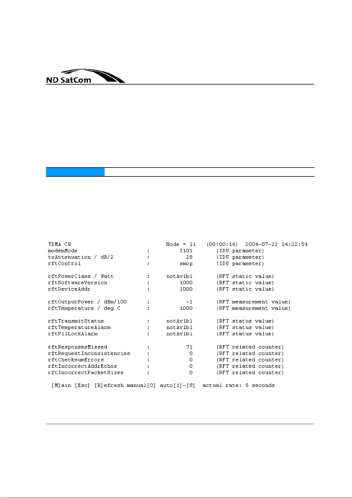
Node Run Modes
NOTICE The IDU has to run in Permant Mode (Vers. 5.5, 5.6)
SkyWAN
Operation Manual
even at the maximum symbol rate rs = 5 MBaud. This mode is suitable for
signal quality measurements.
• Transmission of phase-alternating carrier (modem mode 32 kk): In this
sub-mode the Modulator alternates the phase every symbol by 180 °. This
results in a spectrum with two distinctive lines half the symbol rate apart
from the carrier frequency. This mode is suitable for ro ugh measureme nts
of 3rd -order intermodulation products.
All mentioned CW sub-modes are single-channel modes. However, the frequency channel used for the tests is selectable, enabling all channe ls of interest
to be checked one after the other without modifying network parameters.
Provided SMCP (SkyWAN® Monitor and Control Protocol) has been selected
(rftTransmitterControl) for IDU-RFT communication, the RFT is polled once per
second for the following measurement and status values:
®
Figure 2-2: TDMA CW Screen
2-8 Rev. B1.4, 31-08-2006
Page 33

SkyWAN®
Operation Manual
Node Run Modes
The transmit power attenuator can be adjusted to the desired power level by
modifying the value of the parameter txAttenuation.
The data fields shown on the TDMA CW screen have the following meaning:
• powerClass: Rated output power of the RFT expressed in Watt.
• softwareVersion: Version of software running on the RFT controller.
• Device address: Hardware address of the RF transmitter.
– 1000: value not available
– else: hardware address
• outputPower: Output power expressed in dBm/100.
• temperature: Housing temperature expressed in °C.
• transmitStatus: Set to 1 when the RFT's high power amplifier is enabled.
• temperatureAlarm: Set to 1 when the housing temperature is out of range.
• pllLockAlarm: Set to 1 when the PLL (Phase Locked Loop) is out of lock.
• responsesMissed: Number of messages not replied to by the RFT.
• requestInconsistencies: Number of inconsistent packets received by
RFT.
• checksumErrors: Number of packets with incorrect checksum received
by IDU.
• incorrectAddrEchos: Number of packets with incorrect address echo received by IDU.
• incorrectPacketSizes: Number of packets with incorrect size received by
IDU.
Rev. B1.4, 31-08-2006 2-9
Page 34

Node Run Modes
Operation Manual
2.4 Start-up of Node
A node starts normally in operational mode with the permanent configuration.
The node starts only in diagnostic mode in case of invalid configurations or oth
er hardware or software failures.
A start-up of a node can be initiated by two possible types of reset, hard reset
and soft reset. Each reset type is associated with different start-up conditions.
The start-up distinguishes between a cold start and a warm start.
The cold start state is entered either as the result of a power-on event (cold
start), or a reset-button-press event. The reset-button- press event distinguishes
between a regular reset and a diagnostics reset. The diagnostics reset is gen
erated by the user by pressing the reset button for more than 5 seconds.
SkyWAN
®
-
-
Figure 2-3: Reset buttons on IDU 5000 front and back side
After a regular hard reset the permanent image is booted.
• The warm start is triggered by S/W means as the result of a fallback or a
network management event.
To perform a soft reset, launch the configuration manager. Click consecutively
on IDU overview and IDU Administration. Assign the attribute „AdminStationRe
setTime“ a value in the past. Then press the reset IDU now button. Whether
the soft reset should result in booting the permanent or the temporary image de
pends on the value of the attribute "adminStationReset Type".
Table 2-1 summarizes the reset types.
2-10 Rev. B1.4, 31-08-2006
-
-
Page 35

SkyWAN®
Operation Manual
Node Run Modes
Reset/start type Possible modes Events
S/W reset / warm start Perm / temp / diag Fallback / network
mgmt
H/W reset / cold start perm / diag reset-button-press /
power-on
Table 2-1: R eset Types
The modes denoted in Table 2-1 are entered either in reaction to a start-up con-
dition, or for release management purposes.
Rev. B1.4, 31-08-2006 2-11
Page 36

Node Run Modes
SkyWAN
Operation Manual
®
2-12 Rev. B1.4, 31-08-2006
Page 37

SkyWAN®
Operation Manual
Node Management
3 NODE MANAGEMENT
A SkyWAN® node can be managed by several means for configuration, monitoring and logging.
3.1 Configuration
The configuration pararameters of a SkyWAN® node are logically organized in
a tree structure as defined in the SkyWAN
®
SNMP MIB structure.
The SkyWAN® configuration file contains the complete, consistent node configuration. The SkyWAN® software reads the configuration file and ap p lies it du ring the start-up initialization.
The configuration file has the fixed name "SkyWANCF.PRM"; it is located in the
directory in/config on the IDU file system. The configuration file is a binary file
that is not human readable. It can be up/downloaded to a PC.
There are three ways to configure a SkyWAN® node. They are described in the
following sections.
3.1.1 Loading a new configuration file and restarting the unit
The configuration by transfer of configuration files is available in both, diag nostic and operational mode.
This is best suited for initial provisioning, if many parameters have to be
changed at one time and if the station is not already in a running network. It is
recommended to use the SkyWAN
configuration file. The SkyWAN
user interface, presents the configuration in a clear structure and checks the
consistency of the configuration. For more details about the handling of this tool,
refer to the SkyWAN
®
Configuration Manager Guide.
®
Configuration Manager to generate the
®
Configuration Manager provides a graphical
Direct change of a configuration file using an ASCII editor can also be done.
However, this is not recommended. The Windows tool SkyConf must be used
to convert the configuration file into an ASCII file and vice versa. It is necessary
to copy skyconf.exe into the directory where the file to convert is stored in. Then
in a DOS window type skyconf -t txt -i - skywancf.txt -o skywancf.prm to convert
the ASCII file into a binary file. To convert the binary file into an ASCII file use
skyconf -t bin - i skywancf.prm -o skywancf.txt.
Rev. B1.5, 01-03-2007 3-1
Page 38

Node Management
3.1.2 Using SNMP
3.1.3 Telnet session
SkyWAN
Operation Manual
The configuration per SNMP (V1 and V2c) is available in operational mode only.
This mechanism is not recommended for the initial provisioning, it is more appropriate for configuration changes of the working system without interruption
from a central point. The parameter changes take effect immediately, if they are
accepted by the SkyWAN
®
node that validates the parameters. This mechanism can be used if there is a central network management station with a SNMP
MIB browser like the SkyWAN
between the network management station and the SkyWAN
®
NMS. There must be a working IP connection
®
node. The modified configuration can be saved as configuration file. During the save action the
new parameter values are written to a temporary file and during the freeze
phase the temporary file (*.tmp) is changed into a perma nent file (*.prm) replac
ing the former permanent file.
The configuration per Telnet session is available in operational mode only.
The user screens allow to configure SkyWAN® nodes using a terminal connection. The terminal connection can be established via Telnet over a working IP
connection to a SkyWAN
the SkyWAN
®
node.
®
node or using a direct serial line PPP connection to
The parameter changes take effect immediately, if they are accepted by the
SkyWAN
®
node that validates the parameters. The modified configuration can
be saved as configuration file.
®
-
3.2 Monitoring
A SkyWAN® node can be monitored by requesting parameter values over
SNMP using a network management tool or by opening monitor user screens
via Telnet sessions. The monitor user screens display sets of attribute values in
a ordered manner. Details are given in
section 8.1 “User Screens over Telnet”
on page 8-1.
3.3 L ogging
A SkyWAN® node provides a logging feature supporting fault analysis and tro ubleshooting.
3-2 Rev. B1.5, 01-03-2007
Page 39

SkyWAN®
Operation Manual
Node Management
The logging feature reports runtime events. These events are stored in a logfile
that can periodically be transferred to at most two logfile servers. Every mo dule
within the SkyWAN
®
operational software has the capability to report events to
the logging module.
More details can be found in section 9.2 “Log File” on page 9-6.
3.4 Node Access
The SkyWAN® node provides the following interfaces for the operator access
from a management - or maintenance - PC:
• A PPP access over the service port
• An IP interface for the access from the Ethernet LAN or via the SkyWAN®
satellite network.
The only interface to access a SkyWAN® node is the service port using PPP
• if the SkyWAN® node starts up the first time
• if the IP configuration is incorrect or if the SkyWAN® node is in "Diagnostic
Mode".
Table 3-1 shows the relationship of interfaces, available network services and
operation mode.
Ping Telnet FTP SNMP
PPP over
service port
Ethernet Diagnostic /
Diagnostic /
Operational
Operational
Operational Diagnostic /
Operational
Operational Diagnostic /
Operational
Operational
Operational
Satellite Operational Operational Operational Operational
Table 3-1: Operator Access Matrix
Rev. B1.5, 01-03-2007 3-3
Page 40
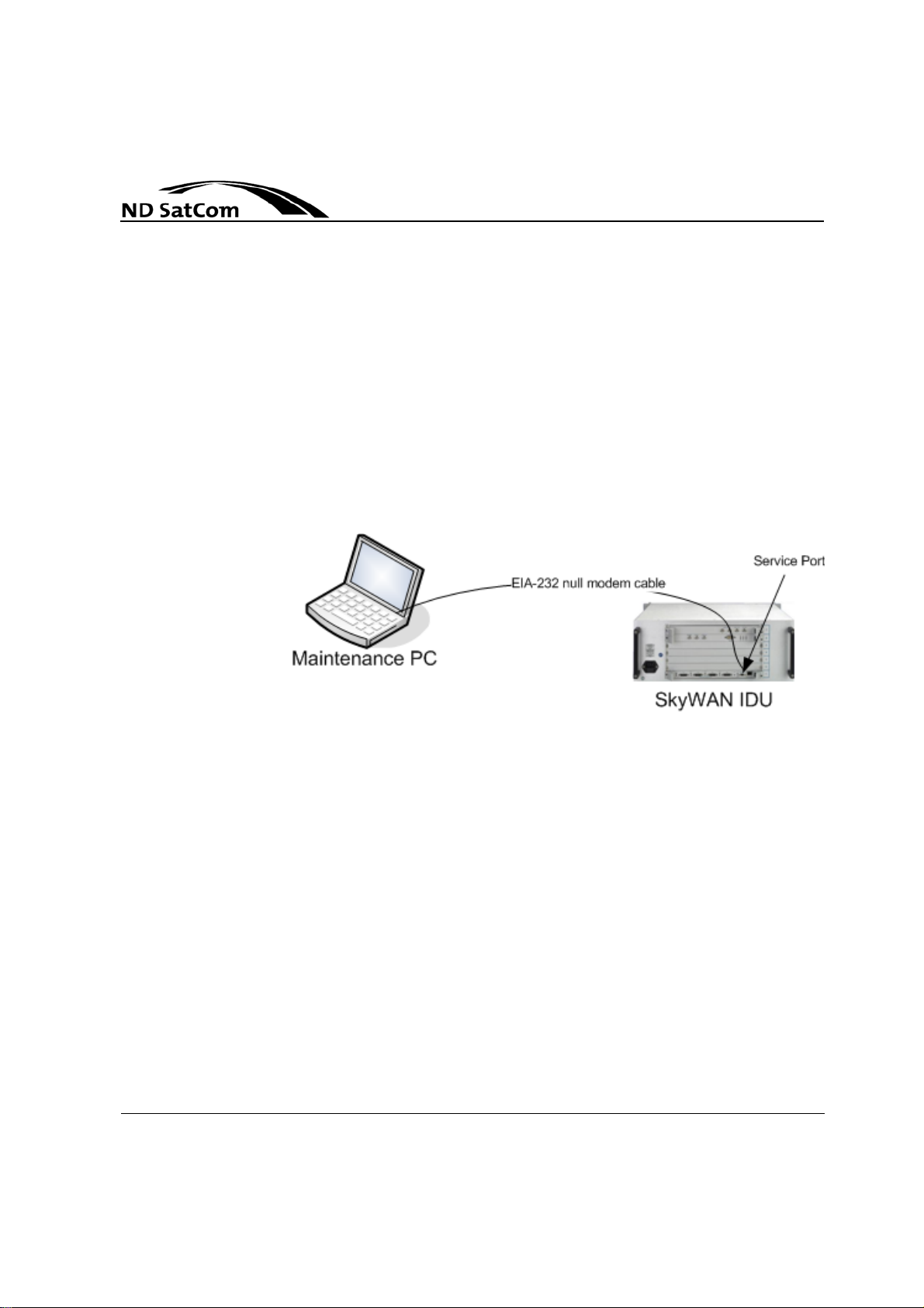
Node Management
3.4.1 Direct Access
SkyWAN
Operation Manual
The SkyWAN® node supports the following using PPP at the service port:
• a Telnet connection for the configuration and troubleshooting via the user
screens
• FTP transfer of
– SkyWAN® software images
– Configuration files
– Logfiles
The access can be established at the service port by means of a local "Null modem". A specific EIA-232 cable connects the "null modem" (cable W59) to the
service port of the SkyWAN
®
node.
®
Figure 3-1: Null-modem link
3.4.1.1 IP Network Addressing
A PPP link always has a local IP address and a remote IP address. The PPP
link is a logical subnet accessible from the maintenance PC and the SkyWAN
node (See
In the default PPP configuration the IDU is server and the PC is client.
The SkyWAN® node works as a DHCP server assigning the IP address
192.168.1.1 to its service port, and the IP address 192.168.1 .2 to the connected
maintenance PC. The TCP/IP properties on the PC must be set up with "o btain
IP address automatically".
3-4 Rev. B1.5, 01-03-2007
Figure 3-1).
®
Page 41

SkyWAN®
Operation Manual
3.4.1.2 PPP Access Restriction
Node Management
To avoid unauthorized access, the PPP access is protected via dedicated user
names and passwords.
Usernames depend on the general status of the SkyWAN® node, indicated by
the DIAG LED. The DIAG LED lights
• yellow in diagnostic mode
• green in operational mode.
Table 3-2 lists the default user names and passwords for PPP access.
Diagnostic Mode Operational Mode
PPP User operator ppp_user
PPP Password go4skywan ppp_password
Table 3-2: SkyWAN® Default Values for PPP Access
NOTICE
The diagnostic mode username and password for PPP access are fix. The
default username and password for th e op er at ion a l mod e can be mo dified,
deleted or additional entries can be created. Please refer to section 4.4 for
more details.
Rev. B1.5, 01-03-2007 3-5
Page 42
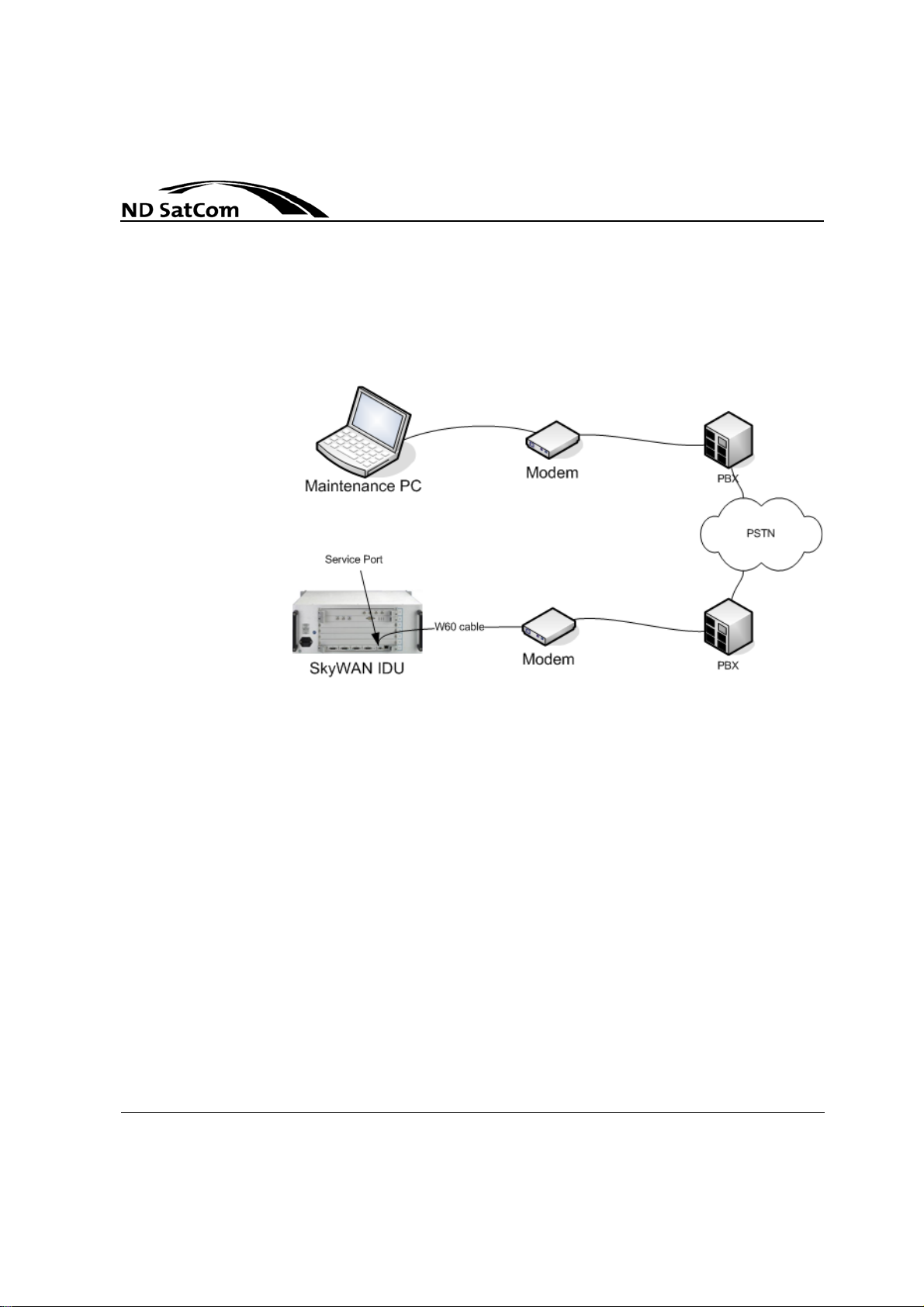
Node Management
3.4.2 Dial-In Access
SkyWAN
Operation Manual
The service port can be accessed with a telephone line modem. A specific EIA232 cable connects the modem (cable W60) to the service port of the SkyWAN
node.
®
®
Figure 3-2: PSTN modem link
The telephone line modem to be used is a specific modem (U .S.Robotics Mod5630B) supporting worldwide PSTN networks. This modem can be ordered
separately at NDSatCom.
3-6 Rev. B1.5, 01-03-2007
Page 43
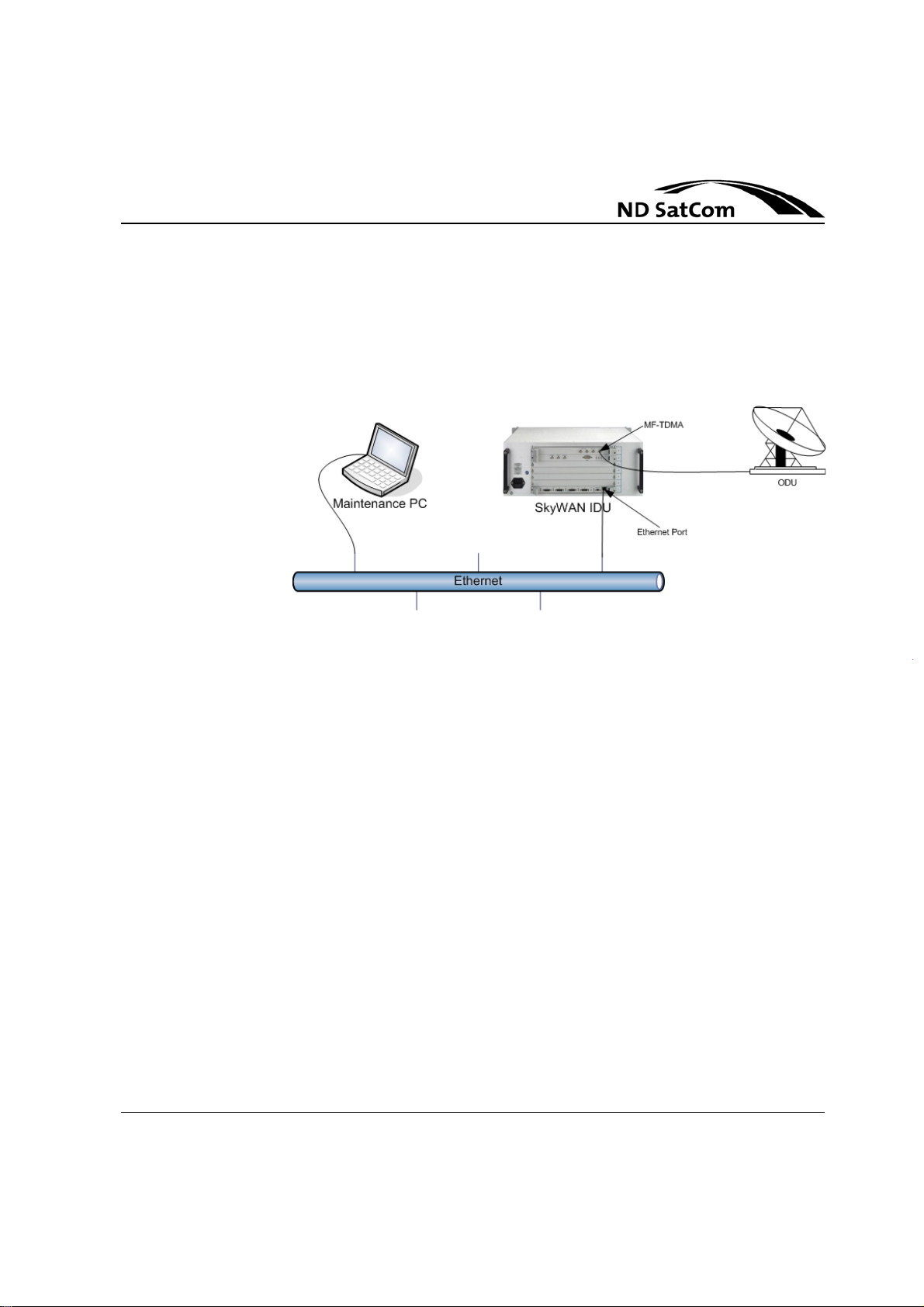
SkyWAN®
Operation Manual
3.4.3 Ethernet Access
Node Management
This IP interface provides the connectivity to the satellite network as well as a
LAN connected to the SkyWAN
®
node. The RJ-45 connector e. g. with a regular
patch cable can be used to connect a maintenance PC.
Figure 3-3: Ethernet Access
Remote SkyWAN® nodes can be accessed by the maintenance PC, provided
they are running in operational mode. The locally connected maintenance PC
can access the SkyWAN
®
node in operational or in diagnostic mode.
3.4.3.1 MAC Addressing
The MAC address is resolved by the interfaces’ address resolution module
which is ARP. The ARP protocol resolves addresses visible on the local LAN
port and the satellite network. A SkyWAN
address out of the NDSatCom pool. No further adjustments concerning ARP
are necessary within a SkyWAN
3.4.3.2 IP Network Addressing
There is no auto-configuration for the IP network address. The SkyWAN® node
uses the IP address from the last successful configuration.
If the configured IP address on the interface is unknown for any reason, it can
be set using the following procedure.
➤ Force the SkyWAN
until the DIAG LED turns to amber.
®
node in diagnostic mode by pressing the reset button
®
node.
®
node has a world-wide unique MAC
Rev. B1.5, 01-03-2007 3-7
Page 44
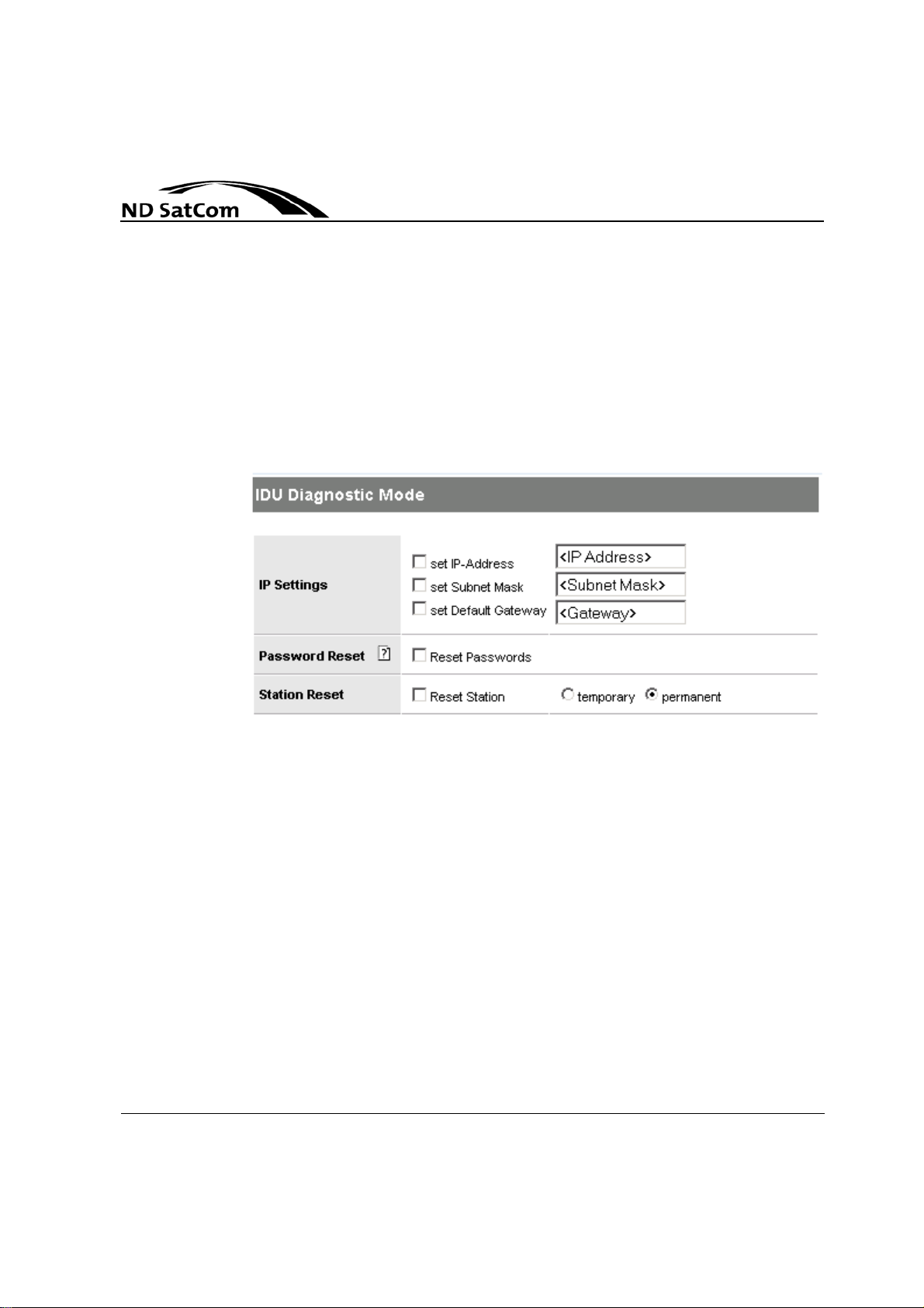
Node Management
SkyWAN
Operation Manual
➤ Establish a PPP connection over the serial port, then open the Configura-
tion Manager.
➤ Select the SkyWAN
®
node and click on the tab "IDU diagnostic mode".
➤ Tick off the "set IP address" and enter the desired IP address.
➤ Tick off the "set Subnet Mask" and enter the desired subnet mask.
➤ Tick off the "set default Gateway" and enter the desired default gateway
(optional).
➤ Push the "send" button.
®
Figure 3-4: IDU Diagnostic Mode Configuration
3.5 Management Services
A SkyWAN® node can be accessed over the three management services Telnet, FTP, and SNMP.
3.5.1 Telnet
SkyWAN® provides the possibility to connect locally a maintenance PC via se-
rial line or remotely via modem (for more technical details about the config uration, refer to Appendix B) to the SkyWAN® node in order to perform
management tasks over Telnet. The maintenance PC must be equipped with a
TCP/IP protocol stack, PPP and a Telnet client. The Telnet session provides the
access to the SkyWAN
within the SkyWAN
serve logging messages, to configure the system and/or to monitor the system
behaviour via attribute values.
3-8 Rev. B1.5, 01-03-2007
®
user screens. The user screen application is running
®
operational software and enables a remote op erator to ob-
Page 45

SkyWAN®
Operation Manual
3.5.2 FTP
Node Management
The SkyWAN® filesystem looks as follows:
• the subfolder config holds up to two configuration files.
• the subfolder relmgmt holds up to two SkyWAN® software images.
• the subfolder logging holds the log files, ready for the transfer to a log file
server.
¦
+-in
¦ +---config
¦ ¦ +------skywancf.prm
¦ ¦ +------skywancf.tmp
¦ ¦
¦ +---relmgmt
¦ +------skywanim.prm
¦ +------skywanim.tmp
+-out
+---logging
+------lowlevel.log
+------current.log
NOTICE
The file system can be accessed from a maintenance PC via FTP over the PPP
connection or over the Ethernet interface.
FTP can be used to transfer new software and configuration files to the Sky-
WAN® node or to transfer logging files from the SkyWAN® node.
These actions are protected by means of a password depending on the status
of the SkyWAN
®
node. Refer to Table 3-3.
Diagnostic Operational
FTP User operator ftp_user
FTP Password go4skywan ftp_password
Table 3-3: SkyWAN® Default Values for FTP Access
In the diagnostic mode user name and password for FTP access are fix. The
default user name and password for the operational mode can be modified,
deleted or additional entries can be created. Please refer to section 4.4 for
more details.
Rev. B1.5, 01-03-2007 3-9
Page 46

Node Management
3.5.3 SNMP
SkyWAN
Operation Manual
The software image and configuration file suffix identifies the fileset, the file belongs to:
• prm permanent fileset
• tmp temporary fileset
The file names are fix and may not be modified.
The parameter adminStationResetType specifies which software and configu-
ration file set to load at the next system bootup . Tw o re se t type s ar e po ssib l e :
• bootPermFileSet: indicates that the 'permanent' file set is to be booted at
the next reset.
• bootTempFileSet: indicates that the 'temporary' file set is to be booted at
the next reset.
The administration of SkyWAN® nodes can be done from a central site via a
Network Management System (NMS). The SNMP management involves with
respect to the SkyWAN
®
network the following components as depicted in
Figure 3-5:
• an SNMP agent residing in every SkyWAN® node
• the SNMP management protocol (SNMP version 2c), used to convey management information between the ag en ts and management stations
• the Management Information Base (MIB) as a collection of managed objects, which is a virtual management SkyWAN® information store. The
Management Information Base specifies the network management varia
bles stored in the agent. Collections of related objects are defined in MIB
modules
• at least one network management station.
®
-
3-10 Rev. B1.5, 01-03-2007
Page 47
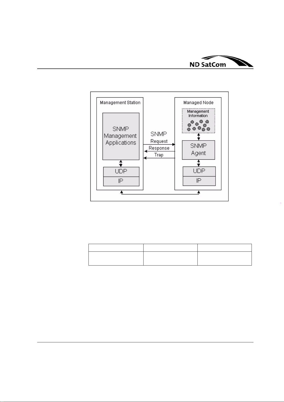
SkyWAN®
Operation Manual
Node Management
Figure 3-5: Manager ÷ Agent Communication Model
3.6 Services vs. Run Mode
The following table provides an overview about the available services in the different run modes of a SkyWAN® node:
Diagnostic Operational BERT
FTP FTP, Telnet, SNMP FTP, Telnet, SNMP
(only locally)
Table 3-4: Services vs. Run Mode
Rev. B1.5, 01-03-2007 3-11
Page 48
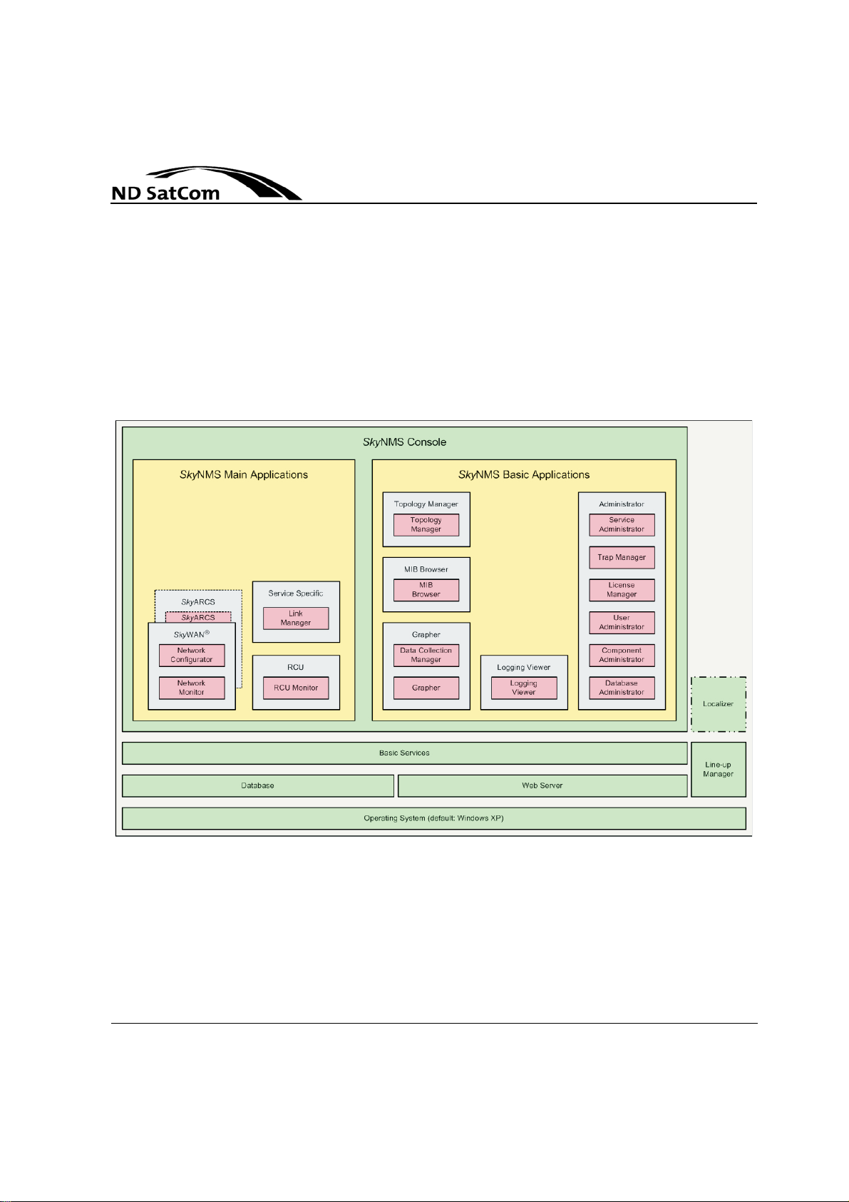
Node Management
3.7 Management Tools
SkyWAN
Operation Manual
SkyNMS consists of the following three components (refer to Figure 3-6):
• an Operating System, which is per default XP SP2,
• a Line-up Manager,
• the SkyNMS Console, which is the core of the network management system and is composed of the components Basic Applications, Main Applications, Database and Web Server.
®
Figure 3-6: SkyNMS Architecture
3.7.1 SkyNMS Console
The SkyWAN® Network Configurator allows to perform the SkyWAN® node configuration in a more user friendly manner, providing a graphical user environment. The Network Configurator is able to generate a configuration file, to
transfer and load it into a SkyWAN
3-12 Rev. B1.5, 01-03-2007
®
node.
Page 49

SkyWAN®
Operation Manual
3.7.2 SkyNMS Main Applications
Node Management
The SkyNMS Main Applications are product or service specific. Thus they can
not be used in general.
At this point of time SkyNMS provides the following Main Applications (see also
Figure 3-6):
SkyWAN
®
• Configuration Manger,
• Software Manager,
• Service Monitor,
• IDU Monitor,
Service Specific
• Link Manager
Redundancy Control Unit
•RCU Monitor
In the following a brief description of each application is given.
3.7.2.1 Configuration Manager
The Configuration Manager allows to perform the SkyW AN® node configuration
in a very user friendly manner providing a graphical user environment. The Con
figuration Manager is able to generate a configuration file, to transfer and to
load into a SkyWAN
®
node.
3.7.2.2 Software Manager
The Software Manager is a network administration tool simplifying the entire
software update process in a SkyWAN
of software is automatically controlled
3.7.2.3 Service Monitor
The Service Monitor is an administrative tool for surveillance of accessibility and
availability of
SNMP requests.
WAN® node could not communicate with the other SkyWAN® nodes in the network. All communication losses are tracked and evaluated to determine total
network availability.
.
SkyWAN® nodes. Selected units are periodically queried via
The MIB object queried indicates the period of time the Sky-
®
network. Distributation and activation
-
Rev. B1.5, 01-03-2007 3-13
Page 50

Node Management
3.7.2.4 IDU Monitor
3.7.2.5 Link Manager
SkyWAN
Operation Manual
The IDU Monitor application establishes a Telnet session to a SkyWAN® IDU.
The system administrator gets access to the user screens of the SkyWAN
which allow a configuration of SkyWAN
®
IDUs.
®
IDU,
The Link Manager is an application offering network administrators as well as
end users an easy way to manage Frame Re lay ISO F RAD an IP con nections
via a Web based graphical user interface. The t ask can be performed from eve
ry PC connected to the SkyWAN® network.
Connections like Video Conferences using ISO FRAD or IP can be scheduled
in advance, activation will be actually performed by the SkyNMS Link Manager
taking into consideration bandwidth management of the connections at the
scheduled time.
In addition to manage scheduled connections in advance, the following tasks
can also be performed for active connections:
• immediate connection termi na tio n and
• increase or decrease of connection duration.
Support of virtual private connections, password protection as well as automatic
capacity and collision checks will also be provided.
®
-
3.7.2.6 Component Administrator
The main tasks of the SkyNMS™ Component Administrator is to show, add,
modify and remove network components in the SkyNMS™ component data
base. Further functionalities are assigning users to components, defining
SNMP parameters of components and valida tin g th e da ta ba se.
3.7.2.7 Topology Manager
The Topology Manager is a GUI based application for monitoring IP an SNMP
controlled devices (e. g. SkyW AN
is continuously indicated.
Additional user definable SNMP GetRequests can be sent to all SNMP capable
devices in the network.
®
nodes). The status of ea ch individual device
3.7.2.8 User Administration
The User Administration provides the functionality of adding, removing, modifying users and their rights concerning the application s of the overall SkyNMS
system.
3-14 Rev. B1.5, 01-03-2007
Page 51

SkyWAN®
Operation Manual
3.7.2.9 Component Administration
Node Management
Any managed user needs a unique login na me (user id entification) and a p assword to login into the Console application. Login into the Console is the only way
to start other applications. After a user is successful logged in he is allowed to
start applications in accordance to his assigned application rights.
The User Administrator provides the following three GUIs:
oUser Administration GUI, which provides the functionality to add, modify and
remove users and the associated user rights,
• a GUI which controls the user access to the Console (name and password)
and
• a GUI which allows an user to change his own passwor d.
The main purpose of the Component Administration is to group single components to logical component group s, which can be assigned to user s. This is su pposed to limit the perception of a user to components, which are of interest for
him. On the other hand the user is not able to monitor or control components,
which are not assigned to him.
The Component Administration provides a GUI to create, modify and delete
component views. Component views are defined by the following properties:
•name,
• description and
• a list of components.
Each component can be linked to a new or existing component view. Components could be linked to any component view and to any number of component
views.
3.7.2.10 Logging Manager
All SkyNMS applications generate unique logbook entries, which are filed in the
database. A logbook entry consists of the following information fields:
•Timestamp,
• Code,
•User,
• Network Component,
• Severity,
• Logging Event as well as
• Application.
Rev. B1.5, 01-03-2007 3-15
Page 52

Node Management
3.7.2.1 1 MIB Browser
SkyWAN
Operation Manual
For visualization of the logbook entries the Logbook Manager is responsible.
Several filters can be set in order to manipulate the amount of shown logbook
entries. Logbook entries can be sorted in ascending and descen ding manner by
each of the information fields mentioned above.
Another function of the Logging Manager is the possibility to import and export
logging data in a standardized manner from and to a file system.
The MIB Browser allows the request and manipulation of real-time MIB attribute
values for selected components which support SNMPv1 or SNMPv2c.
In detail the MIB Browser provides the following capabilities:
• Loading of Standard- and Vendor specific SNMP MIB files,
• Graphical SNMP MIB tree navigation,
• Browsing of single attributes and MIB subtrees by simple node selection,
• Table view of SNMP tables,
• SNMP set requests and
• SNMP requests to multiple nodes.
®
3.7.2.12 Grapher
The main purpose of the Grapher is to visualize the polling results in data collections in a graphical form. From the point of vie w of the Grapher a data collec tion describes exactly one graph, which can be displayed. Within these graph
the polling results of each attribute are represented by a single line with the fol
lowing user definable parameters:
• color,
• thickness and
•style.
For each line the observed attribute name and attribute OID along with the appropriate component name and IP address is displayed.
The x-axis and y-axis of the graph are autoscaled per default but are also scala ble by the user. In addition a grid pattern can be shown. Furthermore the Grapher allows the user to import and export data collections.
3.7.2.13 Event Browser
The SkyNMS Event Browser main purpose is to display event entries filed in the
SkyNMS database in a GUI. The functionality of the SkyNMS Browser is quite
similar to the functionality of the SkyNMS Logging Manager. Each event entry
-
3-16 Rev. B1.5, 01-03-2007
Page 53

SkyWAN®
Operation Manual
Node Management
displayed in the SkyNMS Event Browser Window consists of the following information fields:
•timestamp,
• trap OID or threshold identification,
•user,
• component and
• event description.
Event entries can be sorted in ascending and descending manner by each of
the information fields mentioned above.
Filters can be set in order reduce the amount of visualized event entries. The
following filters can be set:
•timestamp,
• user and
• component.
Furthermore the SkyNMS Event Browser offers the possibility to import and export event data in a standardized manner from the file system.
3.7.2.14 Data Collection Manager
Data collections are the basis for component polling. They serve as input for the
data collector background process, which polls the components. On the other
hand the data collection background process stores the polling results in the
data collection.
The Data Collection Manager provides a GUI, which enables the use r to define,
modify and remove data collections.
3.7.2.15 Event Manager
Two different kinds of events are supported in SkyNMS:
•traps and
• threshold condition indication.
Traps are de fined in the MIB of the managed component s, while threshold con ditions are defined by the Event Manager. A so called event observer background process recognizes the arrival of traps and observes threshold
conditions. If a trap is arrived or a threshold condition is indicated, the event ob
server background process reports this event by storing an event entry into the
database. All events are displayed in the Event Browser application.
The main purpose of the Event Manager is the definition of thresholds conditions. Threshold conditions are part of an already def ine d da ta collectio n. They
-
Rev. B1.5, 01-03-2007 3-17
Page 54

Node Management
SkyWAN
Operation Manual
are defined by a comparison of a polled attribu te value with a fix value or relative
to a fix value. Comparisons can be built with the following logical operators:
• IsEqual,
•IsNotEqual,
• IsGreater,
• IsGreaterOrEqual,
• IsSmaller and
• IsSmallerOrEqual.
A threshold condition can be configured using the following expressions:
• if attrib_val <op> fix_val,
• if (attrib_val#1 <op> fix_val#1) AND (attrib_val#2 <op> fix_val#2),
• if (attrib_val#1 <op> fix_val#1) BEFORE (attrib_val#2 <op> fix_val#2) and
• if (attrib_val#1 <op> fix_val#1) UNTIL (attrib_val#2 <op> fix_val#2).
For each critical situation a start threshold condition (event) and an end threshold condition (rearm) can be defined. This is sup posed to avoid the generation
of traps during the critical situation.
For each event the polling period can be adapted and a alarm can be raised by
the event observer background process.
®
3.7.2.16 SNMP Configurator
This application allows the user to define SNMP parameters for single devices
and subnets. An entry consists of the following parameters:
•Name ,
• IP Address,
•Port,
•Version,
• Read Community and
• Write Community.
3-18 Rev. B1.5, 01-03-2007
Page 55

SkyWAN®
Operation Manual
Global Function
4 GLOBAL FUNCTION
Global functions are those functions available with every SkyWAN® node. Specific applications and configuration issues are described in other chapters.
4.1 Node Licensing
nodeLicenseKey
A unique license key is used to activate specific features within the SkyWAN
node operational software. It is generated for a single SkyWAN® node and cannot be used for another station. The value of the license key is an ASCII string
with a maximum length of 255 characters.
nodeLicenseFeatureDescr
Some SkyWAN® features need to be activated by a valid feature license which
is incorporated in a single unique license key. The license controlled features in
the SkyWAN
®
versions are listed in Table 4-1.
®
ID Feature Rel. 5.10 Rel. 5.33 Rel. 5.4 Rel. 5.5 Rel. 5.6
Ethernet Port license enabled enabled enabled enabled
1
IP Forwarding enabled license license license license
Frame Relay Port 1 license license license license license
2
Frame Relay Port 2 license license license license license
3
Frame Relay Port 3 license license license license license
4
Frame Relay Port 4 license license license license license
5
Isochronous FRAD license license license license license
6
7
Support of SkyWAN® FAD
Frame Relay UNI license license license license license
8
Frame Relay NNI license license license license license
9
Reed-Solomon Coding license enabled enabled enabled enabled
10
11
RDR Mode
a
license license license license license
enabled license license license license
Rev. B1.4, 31-08-2006 4-1
Page 56

SkyWAN
Operation Manual
Global Function
ID Feature Rel. 5.10 Rel. 5.33 Rel. 5.4 Rel. 5.5 Rel. 5.6
Dynamic Routing (OSPF) license license license license license
12
Differentiated IP Services license enabled enabled enabled enabled
13
Platinum Dynamic FB no support license license license license
TCP Accelerator no support license license license license
14
a.Without this license a station can merely operate in LDR mode
Table 4-1: License Controlled Features
Feature license keys can be obtained at ND SatCom.
nodeLicenseFeatureActivationState
The state of the licensed feature availa ble for the SkyWAN® IDU operational
software.
Table 4-2 below explains the different feature states.
®
State Description
active the feature is activated without an expiration date
expiration the feature is activated until the expiration date given
in nodeLicenseFeatureExpirationDate (YYYY-MM-
a
DD)
inactive no license is available for this feature
a.An expiration date of ‚9999-12-31‘ means that no expiration
occures.
Table 4-2: Fe at ur e Activation States
4-2 Rev. B1.4, 31-08-2006
Page 57
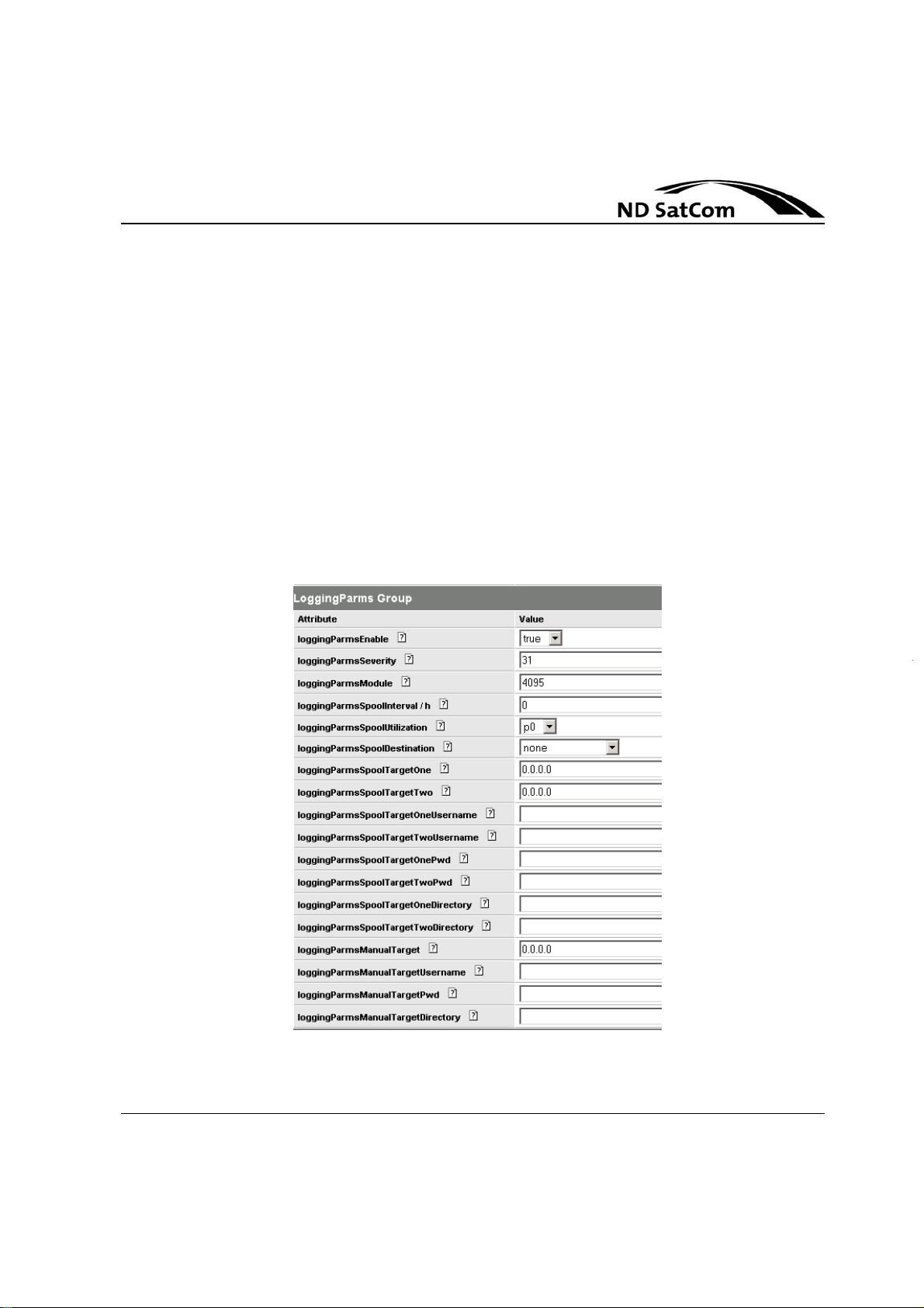
SkyWAN®
Operation Manual
4.2.1 General
Global Function
4.2 L ogging
The purpose of the logging is to report runtime events. Every module within the
SkyWAN
module. These events are stored in a logfile that can periodically be transferred
to at most two logfile servers. As an option, the file is spooled when a user
defined degree of utilization has been reached. Manually initiated file transfers
are supported as well. The last 100 logged events are addi tionally displayed on
the screen if a screen application is active. A logfile has a maximum size of 400
logging entries. If the maximum size of a logfile is reached, the next reported
event overwrites the oldest entry in the logfile. Logging is enabled by setting log
gingParmsEnable to ‚true‘. Configurable logging parameters together with examples are shown in Figure 4-1 below.
®
operational software has the capability to report events to the logging
-
Figure 4-1: Logging Parameter in SkyWAN® NMS ConfigManager Tool
Rev. B1.4, 31-08-2006 4-3
Page 58

Global Function
4.2.2 Severity Levels
Every logging event belongs to one of the following severity levels:
Level Value Severity Explanation
1 1 fatal The fatal class is used in context with fatal error
2 2 critical Critical error describe situations where a S/W
3 4 major This class is used for errors that can not be
4 8 minor This class is used for errors that can be resolved
5 16 info This class is used to notify the operator about
SkyWAN
Operation Manual
conditions that influence the proper operation of
the system. If a fatal error can be recovered by a
RESET a reset trigger is used. If the error can not
be recovered by a reset the LED is set to RED
(e.g. true flash filesystem broken).
module identifies a local problem that influences a
specific system functionality but does not make
the system inoperable. The LED is set to AMBER
in this case.
resolved by the local module but the error does
not have a critical character.
by the local module's error handling.
remarkable system configuration changes e.g.
changes in the network topology, link states and
protocol events. Especially events not directly triggered by the operator should be logged e.g.
cables connect/disconnect.
®
Table 4-3: Logging severity level
The value of the parameter loggingParmsSeverity is a sum. This sum initially
takes the value zero. Then for each severity level L in the range 1 to 5 which
should be logged,
Examples
If all critical and major events should be logged, the value is ‚6‘: .
L 1–()
is added to the sum.
2
21–()
2
31–()
2+
If all events should be logged, the value is ‚31‘. A value of ‚0‘ indicates, no
events are logged.
4-4 Rev. B1.4, 31-08-2006
Page 59

SkyWAN®
Operation Manual
4.2.3 Logging modules
Global Function
Modules for which events can be logged are screened by loggingParmsModule.
The value is a sum starting at 0.
Every supported module is assigned a unique number M:
Number M Value Module
11 base
2 2 cas
3 4 logging
4 8 rtr (router)
5 16 frs (frame relay switch)
6 32 bw (bandwidth)
7 64 satmux (satellite multiplexer)
8 128 pqDriver
9 256 simHw (satellite interface module
hardware)
10 512 tdma
11 1024 fpgHw (frame plan generator hard-
ware)
12 2048 fpg (frame plan generator)
Table 4-4: Logging event modules
Then for each module M, for which events are to be logged, the te rm is
M 1–()
2
evaluated and added to the sum.
Examples
If logging is to be done for the Router and Frame Relay switch, the value would
41–()251–()
be
2
+ 8 16 24=+=
. If the events from all modules are to be logged,
the value would be ‚4095‘. A value of ‚0‘ indicates that no events are to be
logged.
4.2.4 Logfile reset
With loggingParmsReset set to ‚true‘ the logfile ‚current.log‘ will be recreated by
overwriting it with blank characters.
Rev. B1.4, 31-08-2006 4-5
Page 60

Global Function
4.2.5 Erase logfile
If loggingParmsEraseFile is set to 'true', all logfiles ('lghhmmss.sav') saved
manually to the local file system are removed.
4.2.6 Automatic Logfile transfer
Automatic logfile spooling to at most two logfile servers can be done either on
a time interval base (loggingParmsSpoolInterval) or on a log buffer utilization
base (loggingParmsSpoolUtilization). The spool file 'lghhmmss.nnn' to be cre
ated and shipped is a copy of the whole log buffer.
Setting of loggingParmsSpoolDestination to a value of ‚1‘ to ‚4‘ gives the destination of the transfer of the last saved logfile:
Value Effect
none (1) no spooling
spoolTargetOne (2) logfile transferred to first target
spoolTargetTwo (3) logfile transferred to second target
both (4) logfile transferred to both targets
SkyWAN
Operation Manual
®
-
Table 4-5: Logfile Spool Destinations
The next parameters can be configured for up to two logfile servers.
The IP-address of the two logfile servers is configured in:
loggingParmsSpoolTargetOne and loggingParmsSpoolTargetTwo
For the logfile transfer over FTP sessions the following parameters need to be
configured for both logfile servers:
• FTP username (loggingParmsSpoolTargetOneUsername / logging-
ParmsSpoolTargetTwoUsername),
• FTP password (loggingParmsSpoolTargetOnePwd / loggingParmsSpool-
TargetTwoPwd ).
Also the directory path1 on the according logfile servers can be addressed with
the parameters loggingParmsSpoolTargetOneDirectory / loggingParmsSpool-
TargetTwoDirectory.
1.If no directory is specified, the user's home directory is taken as default.
4-6 Rev. B1.4, 31-08-2006
Page 61

SkyWAN®
Operation Manual
4.2.6.1 Time Interval
4.2.6.2 Log buffer utilization
Global Function
Logfile spooling on a time interval base is done by setting loggingParmsSpoolInterval to a value between ‚0‘ and ‚24‘ representing the hourly interval be-
tween two consecutive logfile transfers. The first logfile tran sfer is performed
after the first interval passed.
Examples
• ‚0‘: no transfer
• ‚1‘: one transfer every hour, the first transfer is done one hour after system
start-up
• ‚24‘: one transfer per day, the first transfer is done one day after system
start-up.
Logfile spooling on a log buffer utilization base is done by setting logging-
ParmsSpoolUtilization to a value out of ‚p0‘(1), ‚p50‘(2), ‚p60‘(3), ‚p70‘(4),
‚p80‘(5), ‚p90‘(6) representing the amount of new log messages, as a percent
age of log buffer capacity, required to initiate the creation and shipment of a
spool file (copy of the whole log buffer).
-
Example
• Given a log buffer size of 400 messages, a value of 60% indicates that after
receiving 240 new log messages since the last spooling, a new copy of the
whole buffer should be created and spooled to the specified destination.
4.2.7 Manual Logfile transfer
Manual logfile transfer is done either by initiating spooling to a dedicated logfile
server or FTP-Get Request of the logfile.
4.2.7.1 Initiate logfile spooling
In order to initiate a manually logfile transfer to a dedicated file server set loggingParmsManualWriteToServer to ‚true‘. In doing so the logfile 'lghhmmss.sav'
will be created, a FTP session will be setup to the IP-address given in logging
ParmsManualTarget using a dedicated account (loggingParmsManualTargetUsername and loggingParmsManualTargetPwd) and transferred via FTP to
the targets directory loggingParmsManualTargetDirectory.
After every successful upload the logfile which is created with 'loggingParmsSave' is erased automatically.
Rev. B1.4, 31-08-2006 4-7
-
Page 62
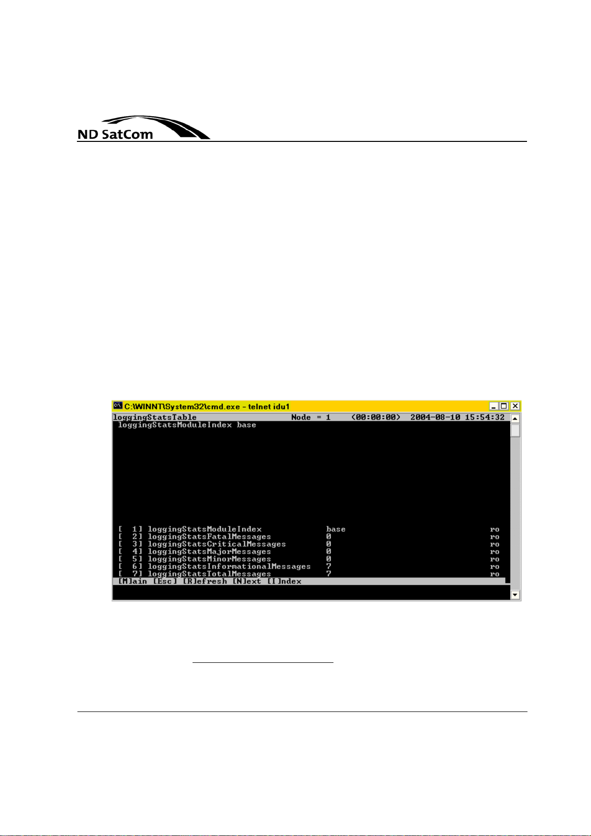
Global Function
4.2.7.2 FTP transfer
If loggingParmsSave is set to 'true', the current logging data is copied to a file
named 'current.log'2. Now start an FTP-session to that station (user: ftp_user;
password: ftp_password), change to directory ‚/out/logging‘ and download the
ASCII-file ‚current.log‘. Open the file with your standard text editor.
Alternatively it is possible to view the logfile SkyWAN® NMS ConfigurationManager.
4.2.8 Logging Statistics
The number of logged messages generated by each software module (s.
Table 4-4 on page 4-5) is given with loggingStatsTable. There is one counter for
each severity level (s. Table 4-3 on page 4-4) of logging messages, and the
sum of all messages generated by each module.
An example of Logging Statistics for the base-modul is given in .
Logging Statistics
SkyWAN
Operation Manual
®
Figure 4-2: Logging Statistics
2.If a file with the character sequence 'current.log' already exists, the file is overwritten in any
case.
4-8 Rev. B1.4, 31-08-2006
Page 63

SkyWAN®
Operation Manual
4.3.1 Save / Freeze mechanism
Global Function
4.3 Station administration
The save / freeze mechanism enables the user to save current node configuration in the configuration file. Furthermore this mechanism allows smooth software migration. The save/freeze mechanism is used by the SkyWAN® NMS
Software Manager Tool when upgrading to a new operational software release.
adminStationSaveSwImage
When set to ‚true‘ the current system software and configuration will be copied
to a temporary file set (skywanim.tmp and skywancf.tmp), which may then be
replaced without impacting operation. This process takes about 1 minute (de
pending on the size of the current image and configuration file).
Possible Values: true(1), false(2) Default: false
After successful saveImage adminStationSaveSwImageTime is updated with
the current station time given the time info of the last saveImage action3. Additionally a logging entry is generated:
„...info System (00439) RELMGMT: Successful save <time info>“
Directory /in/relmgmt on the SkyWAN® IDU file system contains now:
skywanim.prm
skywanim.tmp
-
And /in/config:
skywancf.prm
skywancf.tmp
adminStationFreezeSoftware
When set to ‚true‘ the temporary software an d co nf igu ra tio n curr en tly ru nn in g
on system will be frozen. I.e. the old 'permanent' file set is deleted, and the 'tem
porary' file set is renamed with '.prm' extensions:
'skywanim.tmp' -> 'skywanim.prm'
'skywancf.tmp' -> 'skywancf.prm'.
Possible Values: true(1), false(2) Default: false
After successful freezeSoftware adminStationFreezeSoftwareTime is updated
with the current station time. Additionally a logging entry is generated:
3.Syntax: 'YYYY-MM-DD hh:mm:ss'
Rev. B1.4, 31-08-2006 4-9
-
Page 64

Global Function
„...info System (00363) RELMGMT: Successful freeze <time info>“
Directory /in/relmgmt on the SkyWAN® IDU file system
contains now: skywanim.prm
And /in/config: skywancf.prm
4.3.2 Parameters
adminStationTime
The object 'adminStationTime' allows read and write access to the node's clock,
in order to adjust the internal time to the local time.
Syntax: 'YYYY-MM-DD hh:mm:ss', whereby YYYY = year, MM = months, DD
= day, hh = hours, mm = minutes, ss = seconds.
Example: ‚2004-08-24 16:37:00‘
adminStationSoftwareState
This is a read-only parameter which indicates the system software loaded:
- permanent: the permanent file set is in use, which is always the case
- temporary: the tempo rary file set (skywanim.tmp, skywancf.tmp) is in use,
SkyWAN
Operation Manual
after start-up or after a station reset with adminStationReset
Type set to 'bootPermFileSet'.
which only occurs after a station reset where adminStation
ResetType was set to 'bootTempFileSet'.
®
-
-
adminStationResetTime
Point in time at which the node shall perform a reset. Depending on setting of
adminStationResetType, either the 'permanent' or 'temporary' file set will be
used to load and start the station and to initialize parameters.
Syntax: 'YYYY-MM-DD hh:mm:ss'.
A set request to this parameter using a value designating a time in the past
causes the node to be reset immediately, provided the time value is different
NOTICE
4-10 Rev. B1.4, 31-08-2006
to the parameter's default value.The initial value of this parameter is read
from the configuration file during system start-up. The default value ‚1970-0101 00:00:00‘ is taken if not available.
Page 65

SkyWAN®
Operation Manual
Global Function
adminStationResetType
This object specifies the type of reset to be executed.
Two reset types are possible:
- bootPermFileSet: indicates that the 'permanent' file set is to be booted
at the next reset.
- bootTempFileSet: indicates that the 'temporary' file set is to be booted at
the next reset.
The value may be used to control release changes, in that the latter reset type
is used to initialize the release change, whereby the new software r eplaces the
temporary files. If the update was successful then the node will be running with
adminStationSoftwareState set to 'temporary', i.e. with the new software.
If the update was unsuccessful, then the node will be running with adminSta-
tionSoftwareState set to 'permanent' as the system performed a fallback (to the
previous release) for some reason.
The object has to be set appropriately before next station reset is initiated via
adminStationResetTime. After a reboot this value is se t ba ck to th e d efaul t val
ue 'bootPermFileSet'.
Possible Values: bootPermFileSet(1), bootTempFileSet(2)
Default: bootTempFileSet
-
4.3.3 Passwords
Accessing the SkyWAN® IDU requires authentication with a user name and
password. This can be configured for FTP- and PPP-access.
Querying and configuring the node with SNMP requires read a nd write community password which is also configurable.
Initial values in operational mode:
Application User Name / Password
FTP ftp_user / ftp_password
PPP ppp_user / ppp_password
SNMP read community public
SNMP write community private
Table 4-6: Default Passwords
In diagnostic mode the values are the same for PPP and FTP and can not be
changed: operator / go4skywan
(SNMP access is not available in diagnostic mode)
Rev. B1.4, 31-08-2006 4-11
Page 66
Global Function
NOTICE As a response to a SNMP GetRequest the agent always answers '********'.
SkyWAN
Operation Manual
®
adminPasswordsUsername
A username valid for this node has at least 6 and at the mos t 20 ch aracters.
adminPasswordsPassword
A password has at least 8 and at most 20 characters.
adminPasswordsProtocols
Defines whether ‚ftp‘, ‚ppp‘ or ‚both‘ are accessible by an adminPasswordsUsername / adminPasswordsPassword combination.
Possible Values: ftp(1), ppp(2), both(3) Default: both
adminPasswordsRowStatus
In order to create a new Username / Password combination the parameter adminPasswordsRowStatus has to be set first to ‚createAndWait‘ and then - after
configuring adminPasswordsUsername, adminPasswordsPassword and ad
minPasswordsProtocols - to ‚active‘.
In order to change the username, password or protocol of an existing entry, set
adminPasswordsRowStatus to ‚inactive‘, perform the changes (e. g. new pass
word) and set the row status again to ‚active‘.
-
-
Up to 30 username / password combinations can be configured.
adminCommunitiesReadString
Gives the community name used for read access of the objects' values, which
belong to the modules as defined with the object adminCommunitiesRead
MibModules (see below).
NOTICE
As a response to a SNMP GetRequest the agent always answers '********'. A
communityString has at least 6 chars and at the most 20 chars.
adminCommunitiesReadMibModules
Indicates the MIB modules, from which object' values can be read via SNMP if
the 'communitiesReadString' is known. Every supported MIB module is as
signed a unique number M:
4-12 Rev. B1.4, 31-08-2006
-
-
Page 67

SkyWAN®
Operation Manual
Global Function
module number value MIB module
-- private MIB modules -1 1 node
22rtr
34frs
48tdma
516satmux
632nms
7 64 logging
8 128 reserved
9 256 admin
-- standard MIB modules -10 512 mib-II
11 1024 reserved
12 2048 reserved
Table 4-7: module number for MIB modules
The value is a sum starting at ‚0‘. Then for each MIB module M, from which ob ject values should be read, the term is evaluated and added to the sum.
M 1–()
2
Examples
1. A user should be able to read all objects values from the node MIB module
and the TDMA MIB module. In this case the value is calculated as follows:
11–()241–()
2
+9=
2. A user should be able to read all objects values from the whole MIB. In this
case the value of this object is calculated as follows:
11–()221–()231–()241–()251–()261–()271–()
2
++++++
81–()291–()210 1–()211 1–()212 1–()
2
+++++ 4095=
3. A value of ‚0‘ indicates no object values can be read.
In order to create, modify and d elete read communities the status parameter ad-
minCommunitiesReadRowStatus is used. Possible values are defined in RFC
2579 (Textual Conventions). The 'createAndGo' value is not supported.
Up to 30 read communities can be configured.
Rev. B1.4, 31-08-2006 4-13
Page 68

Global Function
SkyWAN
®
Operation Manual
adminCommunitiesWriteString
Gives the community name used for write access of the objects' values, which
belong to the modules as defined with the object adminCommunitiesWriteM
ibModules (see below).
-
NOTICE
As a response to a SNMP GetRequest the agent always answers '********'.
A communityString has at least 6 chars and at the most 20 chars.
adminCommunitiesWriteMibModules
Indicates the MIB modules, from which object' values can be written via SNMP
if the 'communitiesWriteString' is known. Every supported MIB module is as
signed a unique number M. Table 4-7 on page 4-13 is giving the modules
number for private and standard MIB modules.
The value is a sum starting at ‚0‘. Then for each MIB module M, from which ob ject values should be written, the term is evaluated and added to the
M 1–()
2
sum.
Examples
1. A user should be able to write all objects values from the node MIB module
and the TDMA MIB module. In this case the value is calculated as follows:
11–()241–()
2
+9=
2. A user should be able to write all objects values from the whole MIB. In this
case the value of this object is calculated as follows:
11–()221–()231–()241–()251–()261–()271–()
2
++++++
81–()291–()210 1–()211 1–()212 1–()
2
+++++ 4095=
-
3. A value of ‚0‘ indicates no object values can be written.
In order to create, modify and delete write communities the status parameter
adminCommunitiesRowWriteStatus is used. Possible values are defined in
RFC 2579 (Textual Conventions). The 'createAndGo' value is not supported.
Up to 30 write communities can be configured.
4-14 Rev. B1.4, 31-08-2006
Page 69
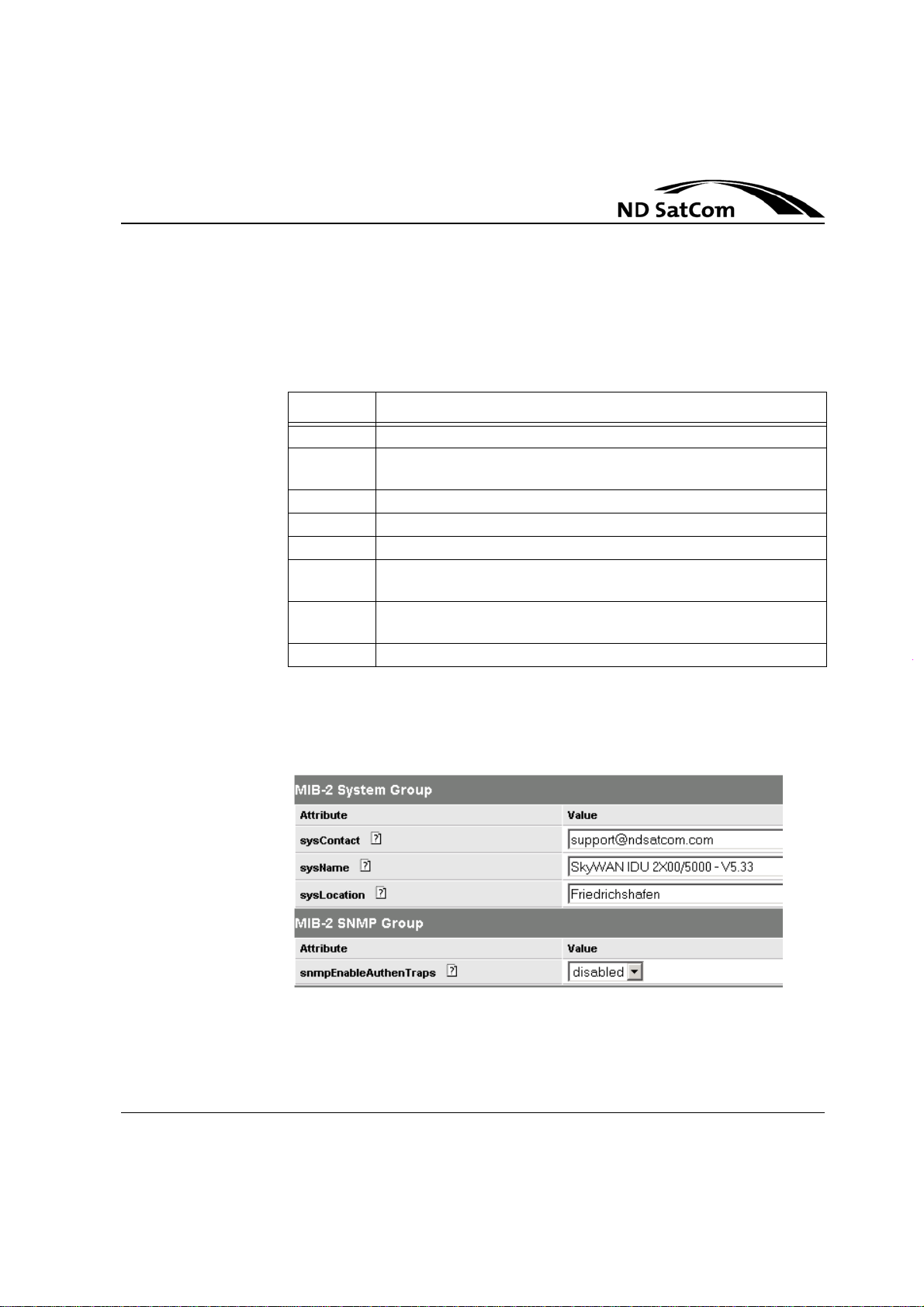
SkyWAN®
Operation Manual
Global Function
4.4 MIB-2 Parameter
Standard Management Information Base for the managemen t of TCP/IP based
internets as documented in RFC 1213 is supported. This includes the modules
in
Table 4-8.
RFC # Description
RFC 1850 The MIB module to describe the OSPF Version 2 Protocol.
RFC 2011 The MIB module for managing IP and ICMP implementations,
but excluding their management of IP routes.
RFC 2012 The MIB module for managing TCP implementations.
RFC 2013 The MIB module for managing UDP implementations.
RFC 2096 The MIB module for the display of CIDR multipath IP Routes.
RFC 2665 The MIB module to describe generic objects for Ethernet-like
network interfaces.
RFC 2863 The MIB module to describe generic objects for network inter-
face sub-layers.
RFC 3418 The MIB module for SNMP entities.
Table 4-8: MIB-2 Modules
On the next page follows relevant MIB-2 parameters as shown with the Sky-
WAN® NMS Configuration Manager Tool.
Figure 4-3: MIB-2 System Group and SNMP Gr oup in Co nfig M an a ger
Rev. B1.4, 31-08-2006 4-15
Page 70

Global Function
4.5 MIB-2 System Parameters
SkyWAN
Operation Manual
®
NOTICE
NOTICE
The following parameters don‘t need to be configured for system operation.
Nevertheless it is highly recommended for ease of maintenance.
sysContact
Gives information about the name of the contact person for this managed node,
together with information on how to contact this person. This string value can
have up to 255 characters.
Example: „John Administrator, Tel.: +1-234-5678, eMail: john.administra[email protected]“
sysName
Is an administratively-assigned name for this managed node. By convention,
this is the node‘s fully-qualified domain name. This string value can have up to
255 characters.
Example: „SlaveNode198“
It is recommended to avoid blanks within the sysName to support the network
discovery function of SkyWAN
HP OV NNM.
®
NMS tools or the "loadhosts"-function of the
sysLocation
Shall inform about the physical location of this nod e. This string value can have
up to 255 characters.
Example: „Shanghai, Branch Office, Some-Street 98, Room 321“
4-16 Rev. B1.4, 31-08-2006
Page 71

SkyWAN®
Operation Manual
Global Function
4.6 MIB-2 Interface Parameters
Figure 4-4: MIB-2 Interface parameters
Rev. B1.4, 31-08-2006 4-17
Page 72

Global Function
Operation Manual
ifAdminStatus
Is the administrative status of an interface. If it is set to ‚down‘ the interface is
not operational. For IP traffic interfaces with index 1, 8 and 9 ifAdminStatus
should be set to ‚up‘. For Frame Relay applications ifAdminStatus should be set
to ‚up‘ for interfaces with index 2, 3, 4, 5 and 6. The state ‚testing‘ indicates that
no operational packets can be passed.
Possible Values: up(1), down(2), testing(3) Default: up
(For a description of node interface: See “Interface MIB Pa rameters” on page 4-
19.)
4.7 MIB-2 IP Parameters
ipForwarding
If set to ‚forwarding‘ the node is acting as an IP ro uter in respect to the forwarding of datagrams received by it but not addressed to it.
Possible Values: forwarding(1), notForwarding(2) Default: forwarding
SkyWAN
®
ipDefaultTTL
The default value inserted into the Time-To-Live field of the IP header of datagrams originated by the node, whenever a TTL value is not supplied by the
transport layer protocol.
Value Range: 1..255 Default: 64
IP Forwarding (Static Routing Entries)
The static routing parameters necessary to establish static routes are explained
section 6.2.2 “Static Routes” on page 6-12.
in
4.8 SNMP Parameter
snmpEnableAuthenTraps
Indicates whether the node is permitted to generate authentication Failure
traps. The value of this object overrides any con figuration informatio n; as such,
it provides a means whereby all authentication Failure traps may be disabled.
If no value is given, it is set to ‚disabled‘ at system start-up.
4-18 Rev. B1.4, 31-08-2006
Page 73

SkyWAN®
Operation Manual
Global Function
4.9 Interface MIB Parameters
The following table shows the node‘s interface index and alias.
Interface index ifAlias
1 Router LAN 1 interface (Ethernet-Port)
2 Frame Relay Serial 1 (User Port 2)
3 Frame Relay Serial 2 (User Port 3)
4 Frame Relay Serial 3 (User Port 4)
5 Frame Relay Serial 4 (User Port 5)
6 Frame Relay WAN 1
8 Router WAN 2 (TDMA 1)
9 Router WAN 3 (TDMA 2)
10 Router WAN 4 (TDMA 3)
11 Router WAN 5 (TDMA 4)
Table 4-9: SkyWAN® IDU Interfaces
Rev. B1.4, 31-08-2006 4-19
Page 74

Global Function
SkyWAN
Operation Manual
®
4-20 Rev. B1.4, 31-08-2006
Page 75

SkyWAN®
Operation Manual
5.1.1 Operation without Self-Reception
Satellite Access
5 SATELLITE ACCESS
5.1 F unction
A slave station without self-reception determines its RTT by mutual exchange
of time stamps and RTT values with the active master station. This enables the
slave to relate its internal high-resolution clock to the ac tive maste r’s on e . By
means of the time stamps a slave is then able to compute its current RTT , which
is used in the same manner as the measured value in the event of self-recep
tion. In order to track the RTT, the described process is repeated periodically.
In an environment where also for the active master station no self-reception is
possible the NFB-DUB mode will be used. In that operation mode all slave sta
tions are having no self-reception. The master RTT must be calculated and
specified as a constant value by the operator via configuration file. This has to
be done with an accuracy of +/-1.5 ms. The master uses hereafter this value for
calculations and distributes this RTT value to suppor t slaves without self-recep
tion in RTT computation. The required accuracy is necessary to get slave stations ranging bursts into the ranging section of the frame. There is not to expect
any negative effect due to this difference, because the dRt on all slaves has the
same value and therefore all slaves are synced to each other while transmitting
on the backward channel(s).
-
-
-
The state of reception will be provided by the cMIB parameter tdmaStatsChan-
AccessCircularState and tdmaStatsChanAccessCircularGrade. A station without self-reception has a circular state of ’syncDataXchg’ meaning, that time
information assigned to the given station is received from the active maste r sta
tion. The circular grade here denotes a measu re for the quality of bursts sent by
the given slave to the active master in conjunction with the quality of reference
bursts received by the given slave. A circle denotes the route slaveTx -> satel
lite -> actMstrRx -> actMstrTx -> satellite -> slaveRx. The circular grade is ideally 100%.
Rev. B1.4, 31-08-2006 5-1
-
-
Page 76

Satellite Access
5.1.2 Operation with Self-Reception
A slave station with self-reception receives some of its own bursts regularl y on
home channel one and with that measures its own RTT to the satellite. For initial
acquisition dedicated time slots (ranging slots) are us ed. Applying an RTT esti
mation, short bursts are transmitted. This provides addi tional guard time and reduces the risk of overlapping with bursts from other stations. As soon as a
station has acquired its current RTT value, it terminates the ranging phase and
starts operational mode. tdmaStatsChanAccessCircularState then changes to
’slfReception’.
tdmaStatsChanAccessCircularGrade denotes the number of transmitted bursts
divided by the number of correctly received burst headers. The basis for deter
mining this value depends on the station type and homeChannelOne: the active
master evaluates its own reference bursts, a slave with homeChannelOne = 1
evaluates its own request and data bursts, and a slave with home ChannelOne
<> 1 evaluates its own data bursts only. A circle designates th e route stationTx
-> satellite -> stationRx. Ideally the circular grade is 100%.
SkyWAN
Operation Manual
®
-
-
5.1.3 Transmit Control
5.1.3.1 Ranging
At start-up the initial value for the Round trip time to the satellite - tdmaParmsStationRtt - is read from configuration file, stored in nonvolatile mem-
ory, and removed from file afterwards. This initial value should be calculated in
view of the satellite's longitude and the station's geographic coordinates. For
low symbol rates the internal modem delay must also be taken into account; its
value in
MBaud).
Depending on tdmaParmsStationRttConfidence the station takes RTT samples
once an hour (beginning with the start-up value) and calculates a new average.
(rttConfidence = ’low’). After 24 samples have been gathered, rttConfidence is
automatically changed to 'high'. For rttConfidence = ’high’ the station ove rwrites
the given station RTT value only after 24 (hourly) samples have been gathered
since start-up. Afterwards the value is updated on an hourly basis.
The tdmaStats parameter currentRtt (see Figure 5-1) is independent of rttConfidence, and always shows the last determined RTT.
s is given by the formula 285/(symbolRate[homeChannelOne] in
μ
5-2 Rev. B1.4, 31-08-2006
Page 77
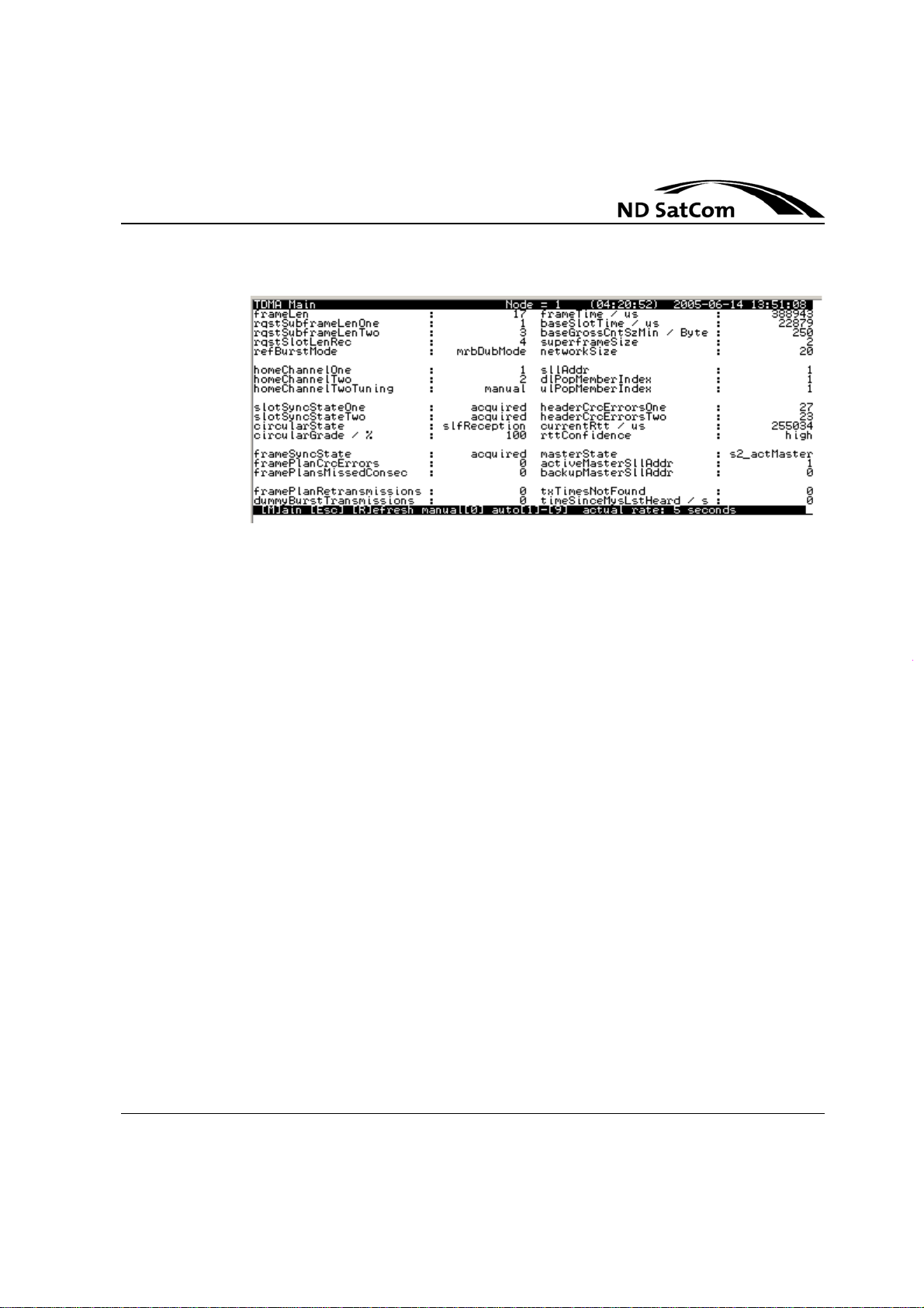
SkyWAN®
Operation Manual
5.1.3.2 Transmit Power Control
Satellite Access
Figure 5-1: TDMA Main Screen
TPC is based on ES/N0 measurements performed by the demodulator. TPC is
independent of external references like beacon signals generated by a satellite.
In the SRB, MRB, or MRB-DUB mode, the stations drive the active master to a n
optimum setting of its transmit power by monitoring the E
S/N0 with which they
receive reference bursts, and possibly ask for an increase or decrease. The a p
plied thresholds ES/N0 min, ES/N0 mod, ES/N0 max can be set individually at each station to consider the respective receiving conditions (The static receiving
conditions of a station are mainly influenced by the antenn a’s figure of merit and
the
transponder’s footprint.). This results in an artificial beacon signal used as a
power reference.
Equally, the slaves asks the active master for an increase or decrease of its
transmit power, in the NFB-DUB mode. In this mode, requests received from
slaves may lead at the active master to a non-optimum setting of the transmit
power, since driving the RFT into compressio n is not de te cte d in th is mode .
The stations adjust their transmit power to achieve an equivalent value for ES/
N
0 of their own bursts. Feedback is either pr ovided by self-reception or indirectly
via the active master which receives bursts from all stations and reports the
measured E
S/N0 values selectively to each slave.
It is ensured that bursts sent on a station’s “tracking” chann el do not permanently drive the RFT into compression. As opposed to the NFB-DUB mode, where
bursts are sent by the active master on frequency channel 3, bursts sent by the
active master in the SRB, MRB, or MRB-DUB mode on frequency channel 1 are
prevented from driving the RFT into compression. In the NFB-DUB mode, driv
-
-
Rev. B1.4, 31-08-2006 5-3
Page 78

Satellite Access
5.1.3.3 Uplink Frequency Control
SkyWAN
Operation Manual
ing the RFT of the active master in to compression is neither detected nor prevented.
TPC is activated by setting tdmaParmsStationModemMode to ’12’ or ’14’.
UFC is used to compensate local drifts of reference frequencies and Doppler
shifts caused by the satellite’s movement relative to the earth stations. UFC lim
its the burst to burst frequency offset to values that can be tolerated by the demodulator. Regarding the bursts received from the active master as a frequency
reference, the slave stations adjust their uplink frequency to achieve an equiv
alent frequency offset. Feedback is either provided by self-reception or indirectly via the active master which receives bursts from all stations and reports the
measured frequency offsets selectively to each slave.
UFC is activated by setting tdmaParmsStationModemMode to ’13’ or ’14’.
®
-
-
5.1.3.4 Reference Burst Modes
Definition of bursts in SkyWAN®:
• Data bursts transmit user data.
• Reference bursts allocate capacity to SkyWAN® IDUs. They are transmitted from the master station to all other SkyWAN® IDUs in the network.
• Request bursts contain requests of capacity from all other SkyWAN® IDUs
in the network to the master IDU.
• Ranging bursts serve for RTT computation at first access.
5-4 Rev. B1.4, 31-08-2006
Page 79

SkyWAN®
Operation Manual
Satellite Access
Definition of modes in SkyWAN®:
Four different operational mod es for re fe re nc e bu rsts and request bursts exist
in SkyWAN
• SRB (Single Reference Burst) mode: All reference bursts are transmitted
on SkyWAN
• MRB (Multiple Reference Burst) mode: Reference bursts are transmitted
on several SkyWAN
• MRB-DUB (Dual Uplink Beam) mode: As MRB, but for cross-strapped
transponders. In addition to MRB, request bursts can be transmitted on two
channels (1 and 2).
• NFB-DUB (No Direct Feedback for Active Master and Dual Uplink Beam).
The NFB-DUB mode represents a single reference burst mode, where the
active master has not to be able to receive its own bu rsts. The X-strapp ed
transponders shall be used. Reference bursts are transmitted only on
channel 3.
®
:
®
´s channel 1
®
channels.
Definition of Populations in SkyWAN®:
• Uplink (UL) Population: All stations transmitting request bursts on the same
frequency channel constitute an UL population. In SRB and MRB mode
there is only one UL population. In MRB-DUB mode two of them exist. In
NFB-DUB up to two UL populations exist, with freqChannel number = 3
both ulPopulations are used with freqChanne l number = 2 only one is used.
• Downlink (DL) Population: All stations sharing a common home channel
one constitute a DL population.
• Reference Burst Consignee (RBC) Population: All stations addressed by
the same regional frame plan constitute an RBC population. The number
of RBC populations equals the number of reference channels.
Rev. B1.4, 31-08-2006 5-5
Page 80

Satellite Access
SkyWAN
Operation Manual
Characteristics of SRB, MRB, MRB-DUB and NFB-DUB
mode:
• In SRB mode, the first demodulator of each slave IDU switches to channel
1 to receive the reference bursts and then switches back on his home chan
nel in order to receive data.
• In MRB and MRB-DUB mode, no switching of the demodulator is required
since data and reference bursts are transmitted on the same channel.
• No reference bursts are transmitted on channels (except channel 1) which
transmit only to active masters or only to second demodulators of slave lo
cations.
• In NFB-DUB a master station sends only on frequency channel 3. The
NFB-DUB mode shall be used to resolve scenarios where no direct master
feedback is possible (Master without Self-Reception), e.g. NFB-DUB mode
eliminates the need for a transponder through which the active master re
ceives its own bursts. Frequency channel 1 and 2 may be used for transmission of ranging, request and data bursts. As opposed to other reference
burst modes, no backup master is supported.
®
-
-
-
Network size and further details
• In previous SkyWAN® software versions SRB mode has been used.
• A SkyWAN® network comprises up to 255 stations per RBC population.
• A SkyWAN® network comprises up to 510 stations altogether.
• This means, in SRB and NFB-DUB mode up to 255 stations are supported
and in MRB and MRB-DUB mode up to 510 stations.
• Each station can get an address (SLL Address) between 1 and 1023.
• As opposed to all other reference burst modes, no backup master is supported by the NFB-DUB mode.
• The master(s) define which stations get permission to enter the network
and on which channels.
5-6 Rev. B1.4, 31-08-2006
Page 81

SkyWAN®
Operation Manual
Satellite Access
Details of MRB-DUB and NFB-DUB:
• Channel 1 and channel 2 contain request bursts. They have identical configuration regarding symbol rate, FEC, DataSlotLength and Reed-Solomon.
• Channel 1 and channel 2 must fix be used for connectivity to the master.
• Two SIC/Demodulator boards are mandatory for master stations op erating
for reception of request bursts.
• In MRB-DUB mode channels with reference bursts are received on the first
slave-demodulator board; channels without reference bursts are received
on the optional second slave-demodulator board.
• In NFB-DUB mode only one SIC-demodulator per slave sta tion is allo wed
e.g. all bursts are received on home channel 3 and only a STAR mode is
possible.
• The satellite transponders must provide the required connectivity.
5.2 Parameter
This section describes the network, station and master control parameters of
the SkyWAN
operation without self-reception and Transmission Control (Ranging , TPC and
UFC) is explained.
Parameters with an asterisk are read-only parameter, i. e. SNMP-Set on these
parameters is not possible.
®
node. Furthermore station operation with self-reception, station
5.2.1 Network Parameter
Network parameter are to configure the physical layer of the networks air inter face. They comprise the TDMA, data container size and for each satellite channel: dataSlotLen, coding scheme, modem symbolrate, Tx- and Rx frequencies.
The network parameters except frequencies must be the same in all the stations belonging to the same network. That is the reason why the values of these
parameters can only be changed by overwriting the configuration file SKY
WANCF.PRM (e.g. using the configuration tool). In order to avoid confusion
and inconsistencies no possibility is given to modify them via SNMP Set
commands or via the User Screens.
-
Rev. B1.4, 31-08-2006 5-7
Page 82
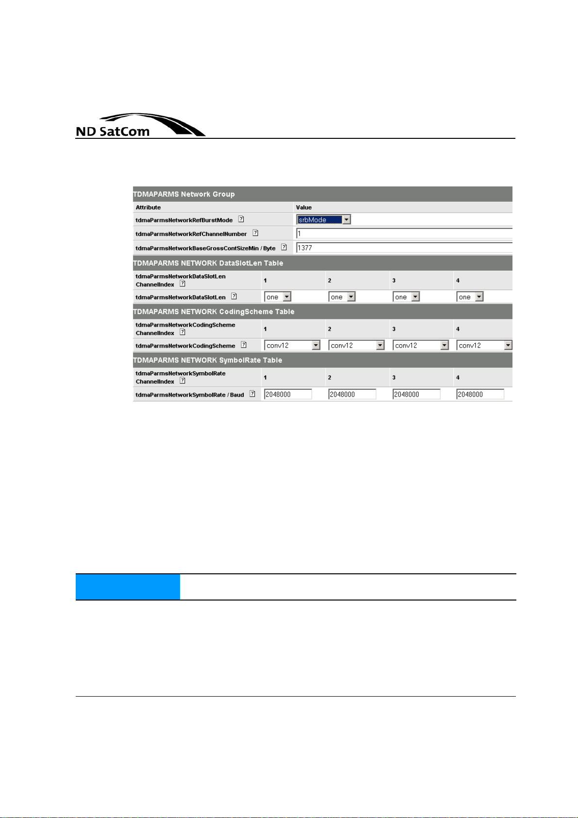
Satellite Access
SkyWAN
Operation Manual
®
NOTICE
Figure 5-2: TDMA Parms NW view in SkyWAN® NMS ConfigManager (1)
tdmaParmsNetworkRefBurstMode
Select the Reference Burst Mode:
• (1) srbMode: Single Reference Burst (SRB ) mo de
• (2) mrbMode: Multiple Reference Bursts (MRB) mode
• (3) mrbDubMode: MRB mode combined with Dual Uplink Beam (DUB)
mode
• (4) nfbDubMode: No Direct Feedback for Active Master (NFB) and Dual
Uplink Beam (DUB)mode.
Default: (2) mrbMode
In MRB-DUB and NFB-DUB mode, the settings: dataSlotLen, coding
scheme, modem symbolrate on channels 1 and 2 must be identical.
5-8 Rev. B1.4, 31-08-2006
Page 83

SkyWAN®
Operation Manual
Satellite Access
tdmaParmsNetworkRefChannelNumber
Total number of channels which contain reference bursts.
Value Range: 1 ... 8
Possible values depending on RefBurstMode:
• SRB-Mode:
-- List of reference channels: (1)
-- Permissible value range: 1 (static setting)
• MRB-Mode Default:
-- List of reference channels: (1, 2, ..., refChannelNumber)
-- Permissible value range: 1 <= refChannelNumber <= 8
• MRB-DUB mode :
-- List of reference channels: (1, 3, ..., re fCh ann elNumber + 1)
-- Permissible value range: 1 <= refChannelNumber <= 7
• NFB-DUB-Mode Default:
-- List of reference channels: (3)
-- Permissible value range: 1 (static setting)
NOTICE
tdmaParmsNetworkBaseGrossContSizeMin
Minimum number of bytes (including burst header, payload and descriptors but
excluding channel coding redundancy) constituting a gross container o f a base
slot. This value equals the parameter baseGrossContSize if block coding is dis
abled on frequency channel 1. If block coding is applied, the station extends the
gross container to optimize the data to overhead ratio and, furthermore, to ac
commodate the block code redundancy.
Value Range: 1..1600 Default: -
The lower and upper limit depend on further system parameters. However , a
value greater than 1600 Byte is unacceptable in any case.
tdmaParmsNetworkDataSlotLen
Several base slots can be combined in one data slot on any channel. In MRBDUB and NFB-DUB mode the settings on channels 1 and 2 must be identical.
Possible Values: One (1), Two (2), Four (4), Eight (8) Default: One (1)
-
-
Rev. B1.4, 31-08-2006 5-9
Page 84

Satellite Access
SkyWAN
Operation Manual
tdmaParmsNetworkCodingScheme
Specifies the FEC coding scheme used on the given frequency channel:
# Coding Scheme Explanation
1 uncoded
2 conv78 CCR = 7/8
3 conv34 CCR = 3/4
4 conv12 CCR = 1/2
5 conv78PlusRs CCR = 7/8 plus Reed-Solomon coding
6 conv34PlusRs CCR = 3/4 plus Reed-Solomon coding
7 conv12PlusRs CCR = 1/2 plus Reed-Solomon coding
1.CCR denotes the rate of the convolutional code.
Table 5-1: Coding Schemes
In MRB-DUB and NFB-DUB mode, the settings on channels 1 and 2 must be
identical.
Possible Values: see Table 5-1 Default: conv12
1
= 1/1 (BER test only)
CCR
®
tdmaParmsNetworkSymbolRate
Nominal satellite modem symbol rate on the given frequency channel. The data
rate on frequency channel k is given by the combination of symbol rate and
code rate: dataRate[k] = symbolRate[k] x codeRate[k] x 2 bit/symbol.
In MRB-DUB and NFB-DUB mode, the settings on channels 1 and 2 must be
identical.
Value Range: 64000..5000000 (Baud) Default: 5000000
5-10 Rev. B1.4, 31-08-2006
Page 85
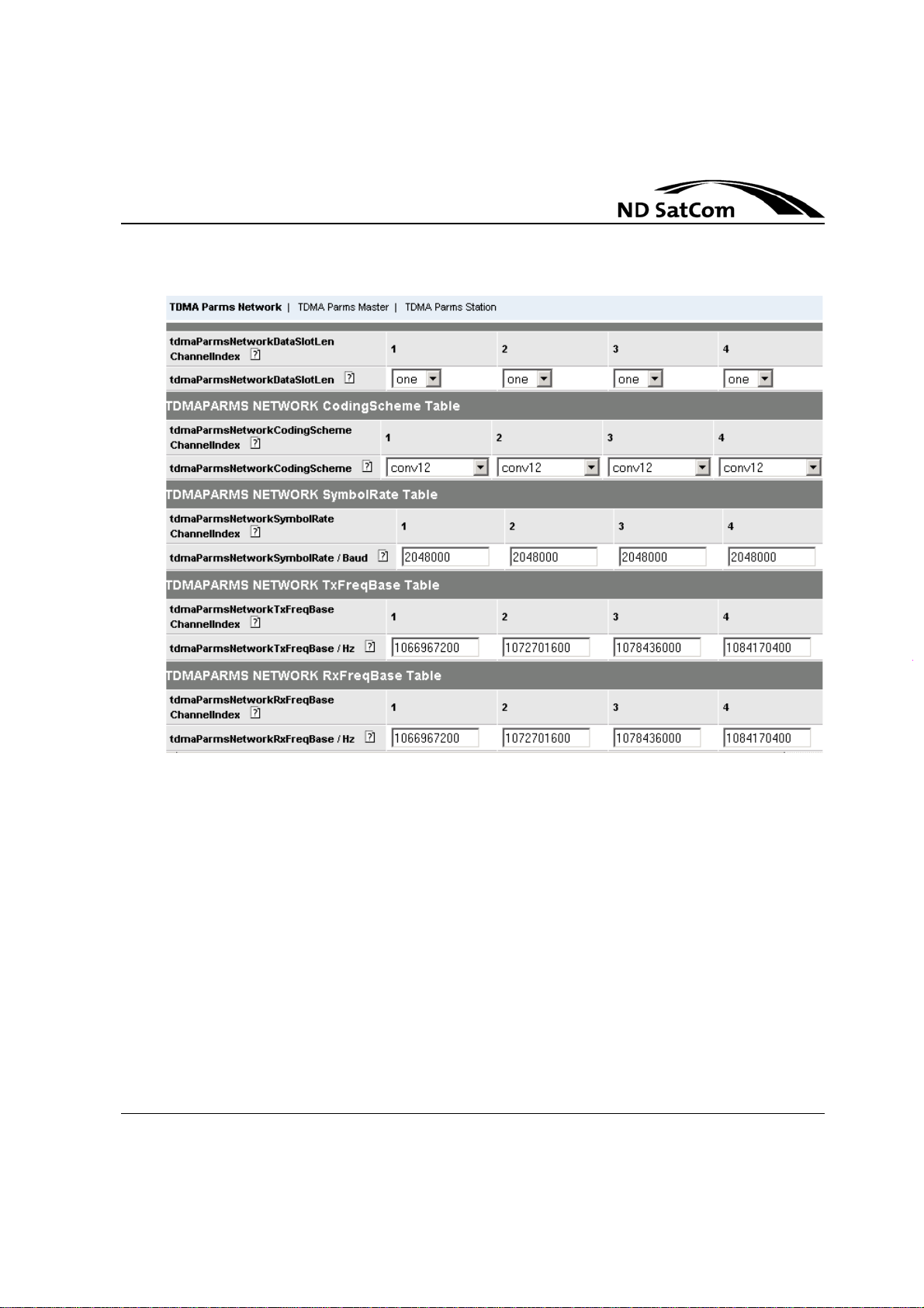
SkyWAN®
Operation Manual
Satellite Access
Figure 5-3: TDMA Parms NW view in SkyWAN® NMS ConfigManager (2)
tdmaParmsNetworkTxFreqBase
Nominal L-Band transmit frequency on the given frequency channel.
Value Range: 950000000..1525000000 (Hz) Default: 10X0000000
Each value can be taken with a granulation of 1 Hz.
tdmaParmsNetworkRxFreqBase
Nominal L-Band receive frequency on the given frequency channel.
Value Range: 950000000..1700000000 (Hz) Default: 10X0000000
Each value can be taken with a granulation of 1 Hz.
Rev. B1.4, 31-08-2006 5-11
Page 86
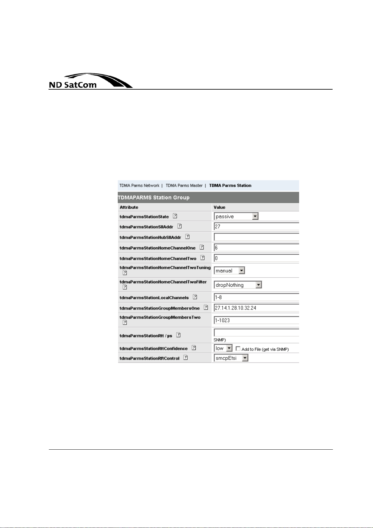
Satellite Access
5.2.2 Station Parameter
The listed parameters in Figure 5-4 and Figure 5-5 are specific to each station.
They can be changed individually at any time. One restriction is that two stations cannot be configured with the same StationSllAddress. Remember that
you must enter the correct
A SkyWAN® IDU will not enter the network if access for this station is not defined.
license key for each node.
SkyWAN
Operation Manual
®
Figure 5-4: TDMA PARMS Station Parameter (1)
5-12 Rev. B1.4, 31-08-2006
Page 87

SkyWAN®
Operation Manual
Remark:
Satellite Access
tdmaParmsStationState
Administrative state of the station:
# State Description
1 passive Tx chain disabled and Rx chain
enabled
2 active Tx and Rx chain enabled
3 lBandLoop modulated and f-converted sig-
nal is looped back
4 basebandLoop baseband signal is looped back
Table 5-2: Station states
Loopback modes are only feasible if the station is on the same LAN as the
NMS station, as it will be disconnected from the satellite.
The setting of tdmaParmsStationState is ignored if a non-operational mode
(see tdmaParmsStationModemMode) has been selected.
Possible Values: passive (1), active (2), lBandLoop (3), basebandLoop (4)
Default: active
tdmaParmsStationSllAddr
The station´s address on the satellite channel. The parameter is called SLL
(Satellite Link Layer) address because internally another address type is used
which however is not visible.
It is not possible to modify the addresses of masterOne or masterTwo with
SNMP or telnet, neither to assign one of those addresses to a pure slave.
Value Range: 1..1023 Default: -
The Station will only access the network if this value corresponds to the defi-
NOTICE
Rev. B1.4, 31-08-2006 5-13
nition in the active master. In the master station, a data set must exist with
tdmaParmsMasterDlPopIndexStationIndex = StationSllAddr and tdmaParmsMasterDlPopIndex = HomeChannelOne.
Page 88

Satellite Access
SkyWAN
Operation Manual
tdmaParmsStationHubSllAddr
List including the SLL addresses of up to two hub stations. If hub SllAd dr is no t
empty, all user forwarding traffic received from a sender other than one of the
listed hub stations is dropped. The permissible value range is linked with the
RDR (Regular Data Reception) feature that is to be enabled by license key.
Only if RDR is enabled, hubSllAddr may be empty (i.e. ''). In LDR (Limited Data
Reception) mode (opposite of RDR mode), hubSllAddr must contain at least
one SLL address (i.e. 'x' or 'x.y').
Value Range: 1..1023 Default: -
tdmaParmsStationHomeChannelOne
First of at most two channels on which the station receives data bursts. The first
SIC/demodulator board of the IDU tunes on this channel. In MRB and MRBDUB mode homeChannelOne must be a channel with reference bursts. In NFBDUB mode all slaves have channel 3 as homechannelOne. Hence, frequency
channel 3 need to be located on a transp onder whose DL footprint covers all o f
them.
The homeChannelOne setting of master stations is fixed to 1 in all reference
burst modes and cannot be changed. Once a slave station is registered, it
adapts its homeChannelOne setting automatically to a possibly chan ged down
link population index. The parameter can only be modified via NMS if stationState = 'passive'.
Value Range: ’1’..’8’ Default: ’1’
®
-
tdmaParmsStationHomeChannelTwo
Optional secondary frequency channel on which the station receives data
bursts. The second (optional) SIC/demodulator board tunes on this channel.
Set it to 0 if no secondary SIC/DEMOD board is installed. The system sets this
value to 0 internally if no second demodulator is installed. HomeChannelTwo by
slaves in NFB-DUB mode is always set to 0. At slave stations and at master sta
tions in SRB and MRB mode, the value can be modified via NMS if automatic
tuning is set to "manual". In MRB-DUB and NFB-DUB mode, the homeChan
nelTwo setting of master stations is fixed to '2' and cannot be changed.
• HomeChannelTwo must be different to homeChannelOne
• In MRB and MRB-DUB mode, HomeChannelTwo must not map onto a refer-
Remark:
5-14 Rev. B1.4, 31-08-2006
ence channel.
• In SRB and MRB mode the value can be modified via NMS if automatic tun-
ing is set to "manual".
Value Range: ’1’..’8’ Default: ’1’
-
-
Page 89

SkyWAN®
Operation Manual
Satellite Access
tdmaParmsStationHomeChannelTwoTuning
If set to "automatic", tuning of home channel two can be triggered by the IP
Router (automatic tuning in FMCA mode). If set to manual, the home channel
is fix as configured and tuning commands from the IP Router are ignored. In
MRB-DUB and NFB-DUB mode automatic tuning at master stations is not per
mitted.
-
Remark:
This parameter is irrelevant if no secondary SIC/demodulator board is
present.
Possible Values: manual (1), automatic (2) Default: manual
tdmaParmsStationHomeChannelTwoFilter
Specifies a filter for data frames received on home channel two:
Filter Description
dropNothing Filter disabled
dropFrameRelay Frames sent by SkyWAN
dropIpUcst Unicast frames sent by SkyW AN
dropIpNonUcst Nonunicast frames sent by SkyWAN
dropIp Frames sent by SkyWAN
dropFrameRelayIpUst Frames from SkyWAN
SkyWAN
®
IP Routers are discarded
dropFrameRelayIpNonUcst Frames from SkyWAN
from SkyWAN
®
IP Routers are discarded
dropAll All frames are discarded
Table 5-3: HomeChannel 2 Filter
®
Frame Relay switches are discarded
®
IP Routers are discarded
®
IP Routers are discarded
®
frame relay switches and unicast frames from
®
frame relay switches and non-unicast frames
®
IP Routers are discarded
Remark:
The value of this parameter is irrelevant if no secondary SIC/DEMOD board is
present.
Possible Values: see Table 5-3 Default: dropFrameRelay
Rev. B1.4, 31-08-2006 5-15
Page 90

Satellite Access
SkyWAN
Operation Manual
tdmaParmsStationLocalChannels
List of all frequency channels which may be used by this station for data transmission.
Individual channel identifiers are separated by '.'. Contiguous sequen ces of
channel identifiers can be abbreviated with '-' between the first and last value of
the range. An empty string is not allowed.
Value Range: ’1’..’8’ Default: ’1-8’
Example: Entry ’1-3.5’ specifies that the station can transmit data on the frequency channels 1, 2, 3, and 5.
tdmaParmsStationGroupMembersOne
List of SLL addresses specifying the stations from which data frames received
on home channel one will be accepted by this station. From the given station's
perspective those members constitute a group with respect to reception on its
home channel one.
Individual station addresses are separated by '.'. Contiguous sequences of station addresses can be abbreviated with '-' between the fir st and last value of the
range.
Value Range: ’1’..’1023’ Default: ’1-1023’
Example: Entry 1.3.8-12.20 specifies that the stations 1, 3, 8, 9, 10, 11, 12, and
20 are in the group.
®
NOTICE Stations may be members of more than one group.
tdmaParmsStationGroupMembersTwo
List of SLL addresses specifying the stations from which data frames received
on home channel two will be accepted by this station. From the given station's
perspective those members constitute a group with respect to reception on its
home channel two.
Individual station addresses are separated by '.'. Contiguous sequences of station addresses can be abbreviated with '-' between the fir st and last value of the
range.
Value Range: ’1’..’1023’ Default: ’1-1023’
Example: Entry 1.3.8-12.20 specifies that the stations 1, 3, 8, 9, 10, 11, 12, and
20 are in the group.
NOTICE
5-16 Rev. B1.4, 31-08-2006
Stations may be members of more than one group. The value of this parame ter is irrelevant if no secondary SIC/DEMOD board is present.
Page 91

SkyWAN®
Operation Manual
NOTICE This parameter can only be modified via NMS if stationState = 'passive'.
Satellite Access
tdmaParmsStationRtt
Averaged time span in between transmission and reception of the station's own
bursts on homeChannelOne (average of computed values if station is unable to
receive itself).
The initial value should be calculated in view of the satellite's longitude and the
station's geographic coordinates. For low symbol rates the internal modem de
lay must also be taken into account; its value in s is given by the formula 285/
(symbolRate[homeChannelOne] in MBaud).
The average of the last 24 hourly samples (measured or calculated values depending on the station's self-reception capability) is updated and stored in the
nonvolatile memory of the station.
At start-up the initial value is read from configuration file, stored in nonvolatile
memory, and removed from file afterwards.
Value Range: 0..28500 ( s) Default: -
μ
μ
-
Remark:
tdmaParmsStationRttConfidence
Specifies confidence level in RTT value:
- low (1):
Beginning with the start-up value, the station takes RTT
samples once an hour and calculates a new average. After
24 samples have been gathered, rttConfidence is automatically
changed to 'high'.
- high (2):
The station overwrites the given RTT value only after
24 (hourly) samples have been gathered since start-up.
Afterwards the value is updated on an hourly basis.
The tdmaStats parameter currentRtt is independent of rttConfidence, and
always shows the last determined RTT. RttConfidence is stored in the nonvolatile memory of the station after every update of the RTT average.
Possible Values: low (1), high (2) Default: low
tdmaParmsStationRftControl
Type of protocol used to exchange M&C information with the RFT:
Rev. B1.4, 31-08-2006 5-17
Page 92

Satellite Access
SkyWAN
Operation Manual
# Protocol Description
1 transparent transparent interface
2smcpV1
3smcpV
SMCP-V1
ETSI
4 smcpV3Hub SMCP-V3 hub mode
5 smcpV3HubEtsi ETSI-compliant control with SMCP-V3 hub
mode
6 smcpV3Terminal SMCP-V3 terminal mode
7 refSigEtsi ETSI-compliant control over reference signal
1.SMCP denotes the SkyWAN® Monitor and Control Protocol.
2.ETSI denotes the European Telecommunications Standard Institute.
Table 5-4: RFT Control Protocols
In the mode 'refSigEtsi' it is assumed that the RFT shuts down its SSPA in the
event no reference signal is provided by the station. It is to be used in combina
tion with the station parameter tdmaParmsStationrefSignalMode set to 'txCableOnly' or 'txAndRxCable'. In the case of an error condition (according to ETSI)
tdmaParmsStationrefSignalMode is internally changed from 'txCableOnly' to
'panelOnly' or from 'txAndRxCable' to 'pnlAndRxCab'. The configured value is
restored automatically as soon as the error phase is over.
Possible Values: see Table 5-4 Default: smcp
1
2
-compliant control with SMCP
®
-
5-18 Rev. B1.4, 31-08-2006
Page 93
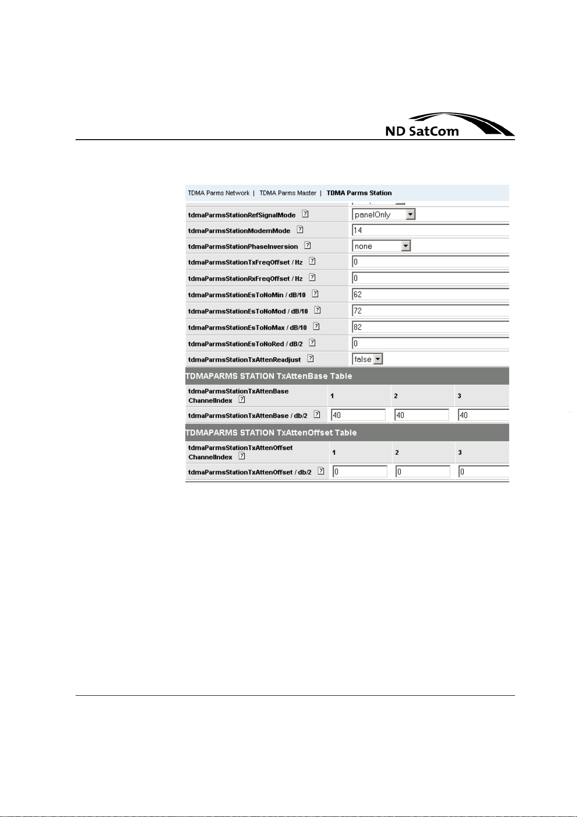
SkyWAN®
Operation Manual
Satellite Access
Figure 5-5: TDMA PARMS Station Parameter (2)
Rev. B1.4, 31-08-2006 5-19
Page 94

Satellite Access
Operation Manual
tdmaParmsStationRefSignalMode
Specifies the reference signal (10 MHz) mode:
# RefSignalMode
1 txCableOnly signal available at TX OUT connector
2 panelOnly signal available at REF OUT connec-
tor
3 txAndRxCable signal available at TX OUT connector
and RX IN connector of primary SIC/
DEMOD board
4 pnlAndRxCab signal available at REF OUT connec-
tor and RX IN connector of primary
SIC/DEMOD board
Table 5-5: Reference Signal (10 MHz) mode
Possible Values: see Table 5-5 Default: txCableOnly
SkyWAN
®
5-20 Rev. B1.4, 31-08-2006
Page 95

SkyWAN®
Operation Manual
Satellite Access
tdmaParmsStationModemMode
In the operational modes, Transmit Power Control (T PC) and Uplink Frequency
Control (UFC) are optional.
Modem Mode Description
11 operational mode; TPC off, UFC off
12 operational mode; TPC on, UFC off
13 operational mode; TPC off, UFC on
14 operational mode; TPC on, UFC on
21kkgg
22kkgg BERT in Tx-Rx1 in L-Band loop
23kkgg
24kkgg BERT in Rx1-only mode
25kkgg BERT in Rx2-only mode
26kkgg BERT in Tx-Rx1 mode
27kkgg BERT in Tx-Rx2 mode
31kk transmission of unmodulated CW signal
32kk transmission of phase-alternating CW signal
33kk transmission of PN-modulated CW signal
Table 5-6: Station Modem Modes
1
1.kk (01 <= kk <= 08) specifies the frequency channel used for BER test and
for CW signal transmission. gg (00 <= gg <= 99) specifies the number of
bursts skipped by the sender between transmissions (BER test only, has no
impact on Rx-only mode).
2.Rx1 denotes reception on the primary SIC/DEMOD board.
3.Rx2 denotes reception on the secondary SIC/DEMOD board.
BERT in Tx-Rx12 mode in baseband loop
BERT in Tx-Rx2
3
in L-Band loop
Remark:
Any value related the secondary SIC/DEMOD board is blocked by the system
if no such board is present.
Possible Values: see Table 5-6 Default: 14
NOTICE From version 5.5 on BERT is not allowed in the Temporary Mode.
Rev. B1.4, 31-08-2006 5-21
Page 96

Satellite Access
SkyWAN
Operation Manual
tdmaParmsStationPhaseInversion
Selects the phase inversion mode:
# Phase Inversion Mode
1 none
2 onTxSide
3 onRxSide
4 onBothSides
Table 5-7: Station Phase Inversion Modes
Possible Values: see Table 5-7 Default: none
tdmaParmsStationTxFreqOffset
Value used to compensate for station-to-station frequency offsets. The input
value plus the nominal transmit frequency (tdmaParmsNetworkTxFreqBase)
give the actual L-Band transmit frequency.
Value Range: -10000..10000 (Hz) Default: 0
Example:
An input value of 200 Hz and a network txFreq of 1,000,000,000 Hz result in
an adjusted transmit frequency of 1,000,000,200 Hz.
®
NOTICE
5-22 Rev. B1.4, 31-08-2006
tdmaParmsStationTxFreqOffset cannot be modified via NMS if UFC is enabled (tdmaParmsStationModemMode = "13" or "14").
The initial value of this parameter is read from the configuration file during system startup and will be removed afterwards from the file.
Page 97

SkyWAN®
Operation Manual
Satellite Access
tdmaParmsStationRxFreqOffset
Value used to compensate for transmit-to-receive frequency offsets. The input
value plus the nominal receive frequency (tdmaParmsNetworkRxFreqBase)
give the actual L-Band receive frequency.
Value Range: -30000..30000 (Hz) Default: 0
Example:
An input value of -200 Hz and a network rxFreq of 1,000,000,000 Hz result in
an adjusted receive frequency of 999,999,800 Hz.
NOTICE
tdmaParmsStationRxFreqOffset cannot be modified via NMS if UFC is enabled (tdmaParmsStationModemMode = "13" or "14").
The initial value of this parameter is read from the configuration file during system startup and will be removed afterwards from the file.
tdmaParmsStationEsToNoMin
Signal quality threshold used for TPC.
A station measures the Es/No (symbol energy to noise power density ratio) of
reference bursts and reports the measured rece ive quality to the active master.
The receive quality classes are given by the parameters tdmaParmsStationE-
sToNoMin, tdmaParmsStationEsToNoMod, and tdmaParmsStationEsToNoMax defining the intervals in which reference b ursts are me asured with Es/No
- below esToNoMin
- between esToNoMin and esToNoMod
- between esToNoMod and esToNoMax
- above esToNoMax.
The active master uses this information to adjust its output power.
Conditions:
50 <= esToNoMin < esToNoMod < esToNoMax <= 220.
There must also be at least 1 dB (i.e. 10 dB/10) difference
between esToNoMin and esToNoMod; similarly between esToNoMod
and esToNoMax.
Value Range: 50..200 (dB/10) Default: 50
tdmaParmsStationEsToNoMod
Signal quality threshold used for TPC.
Refer to description of station parameter tdmaParmsStationEsToNoMin.
Value Range: 60..210 (dB/10) Default: 210
Rev. B1.4, 31-08-2006 5-23
Page 98
Satellite Access
SkyWAN
Operation Manual
tdmaParmsStationEsToNoMax
Signal quality threshold used for TPC.
Refer to description of station parameter tdmaParmsStationEsToNoMin.
Value Range: 70..220 (dB/10) Default: 220
tdmaParmsStationEsToNoRed
Specifies the quantity by which the signal quality of non-reference bursts is to
be reduced relative to the quality with which referenc e bu rsts are received.
tdmaParmsStationEsToNoRed influences the transmit power status values reported by this station for bursts received from other stations. Hence, all members of a station group must use identical esToNoRed settings.
Since this can occur only in networks running in SRB mode, the set tin g es ToNoRed = 0 dB/10 is mandatory in MRB, MRB-DUB and NFB-DUB mode.
Value Range: 0..100 (dB/10) Default: 0
tdmaParmsStationTxAttenReadjust
Causes tdmaParmsStationTxAttenBase and tdmaParmsStationTxAttenOffset
values for all frequency channels (k = 1..8) to be readjusted as follows when set
to true:
txAttenBase[k] := txAttenBase[k] + txAttenOffset[k]
txAttenOffset[k] := 0
®
This feature should be used only during installation, as TPC may try to regu-
NOTICE
5-24 Rev. B1.4, 31-08-2006
late txAttenOffset beyond the 3-dB tolerance: Set once to get within tolerance
again, and then to store the settings once fine-tuning is complete.
Possible Values: true(1), false(2) Default: false
Page 99

SkyWAN®
Operation Manual
Remark:
Satellite Access
tdmaParmsStationTxAttenBase
Base value of the transmit power attenuation on the given frequency channel.
Range: 0 to 31 dB in 0.5 dB steps.
In the event of TPC turned on (tdmaParmsStationModemMode = "12" or "14")
and tdmaParmsStationEsToNoRed > 0 dB/10 at the active master the valu e of
txAttenBase[1] typically differs from the one used by the active master for data
bursts sent on frequency channel 1. In that case txAttenBase[1] refers to refer
ence burst transmissions only.
Although the backup master does not transmit reference bursts, it applies the
same rule; i.e. txAttenBase[1] refers to (hypothetical) reference burst tr ansmis
sions. The value used for request, ranging, and data burst transmissions on frequency channel 1 is then specified by txAttenBase[1] plus esToNoRed, where
both values are given in logarithmic notation.
Set commands to active channels (k <= freqChannelNumber) are rejected if
TPC is enabled. Any modification of tdmaParmsStationTxAttenBase[k] will
cause tdmaParmsStationTxAttenOffset[k] to be reset to its default value.
-
-
Remark:
During system startup the initial value of this parameter is read from the configuration file, stored in nonvolatile memory, and removed from the file afterwar ds.
Value Range: 0..62 (dB/2) Default: 40
tdmaParmsStationTxAttenOffset
Offset value of the transmit power attenuation on the given frequency channel.
Range: -3 to 3 dB in 0.5 dB steps.
Any modification of tdmaParmsStationTxAttenBase[k] will cause
tdmaParmsStationTxAttenOffset[k] to be reset to its default value.
During system startup the initial value of this parameter is read from the configuration file, stored in nonvolatile memory, and removed from the file afterwards.
Value Range: -6..6 (dB/2) Default: 0
Rev. B1.4, 31-08-2006 5-25
Page 100
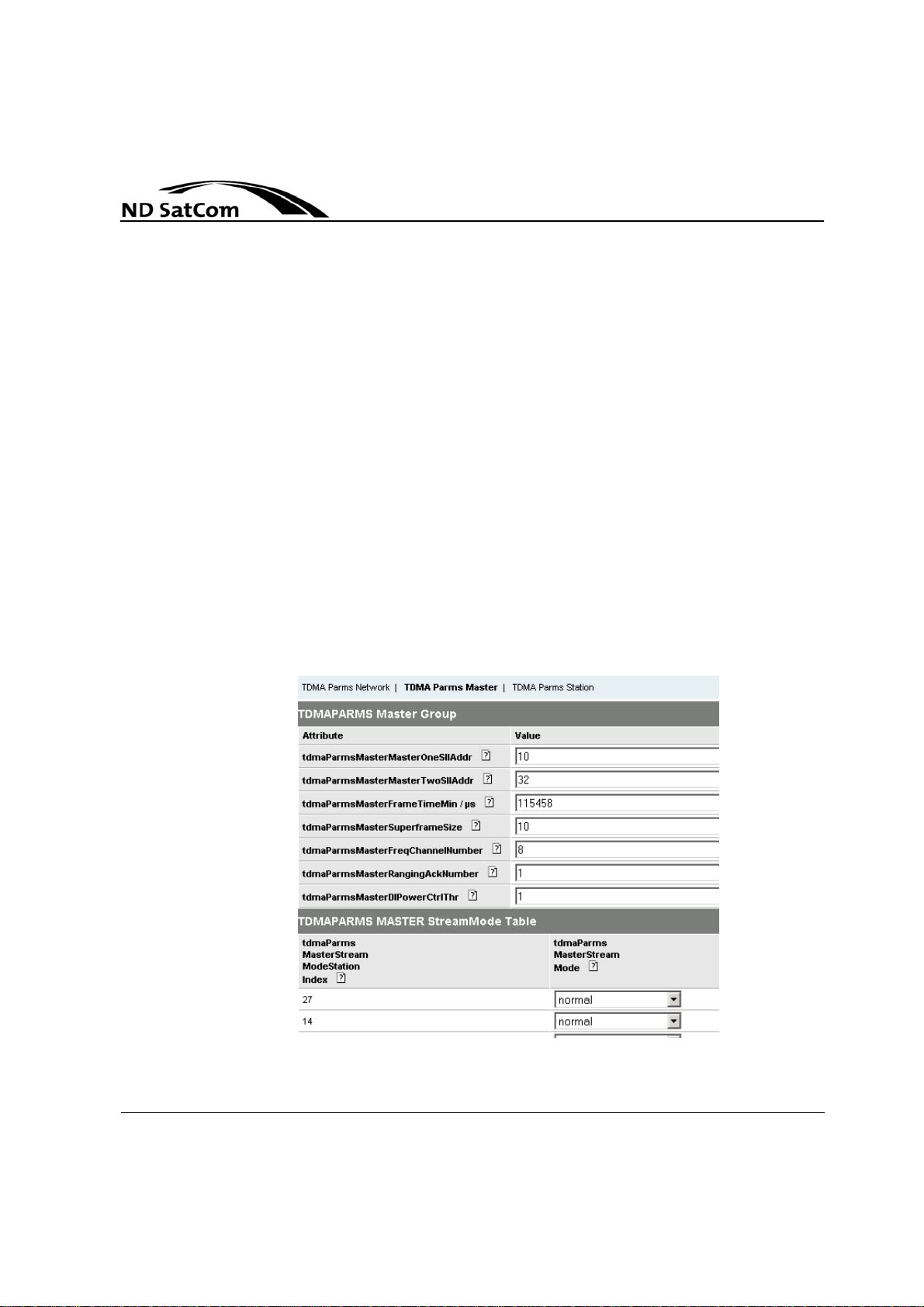
Satellite Access
5.2.3 Master Parameter
Master parameters are mandato ry only at th e ma ster stations of a network.
They describe the superframe structure and define admissible stations. Fur
thermore, they specify up to two master stations, tell which stations are recipients of free slots, how many slots per frame may be used for stream, ho w many
slots are guaranteed to each station on each channel, in which stream mode
each station operates, etc. Settable master parameters that are no n-station-re
lated (e.g. frameTimeMin) can be changed during run-time at the active master
only. The active master stores them in its reference burst headers to inform the
other stations (especially the backup master) about the current settings. This
ensures continuity in the event that the master roles are swapped, as the for mer
backup master would proceed with the late st pa ra m et er set.
In SRB, MRB and MRB-DUB mode settable station-related master parameters
(streamMode, dlPopIndex, freeSlotAssignment, and guaranteedThroughput)
are settable at both masters, but not at pure slaves. Regarding those parame
ters, the operator has to take care that both masters maintain identical values.
In NFB-DUB mode those parameters are settable o nly at the master station, be-
cause no Backup Master feature is possible in this mode.
SkyWAN
Operation Manual
-
®
-
-
Figure 5-6: TDMA Parms Master parameter (1)
5-26 Rev. B1.4, 31-08-2006
 Loading...