SKYTRONIC AMPLIFIER 5.1 SURROUND HT-510 103.153, AMPLIFIER 5.1 SURROUND HT-510 103.156 User Manual

AMPLIFIER 5.1 SURROUND HT-510
103.153 / 103.156
Instruction Manual
Gebruiksaanwijzing
Mode d’Emploi
Gebrauchsanleitung
Brugsanvisning

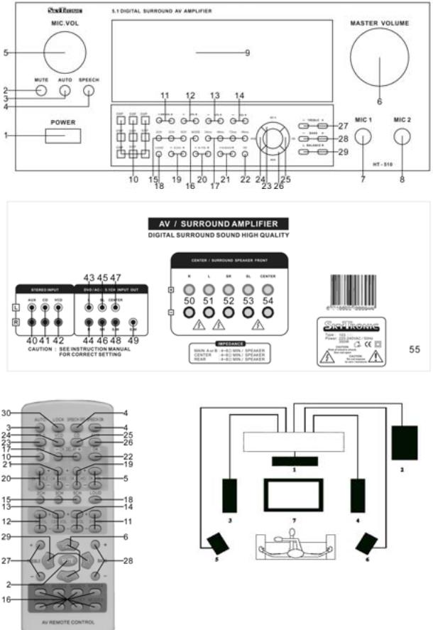
1.Center
2.Subwoofer 3.Front Left 4.Front Right 5.Rear Left 6.Rear Right 7.TV

GB
Congratulations on the purchase of this SkyTronic Karaoke amplifier.
Please read this manual carefully prior to using the unit.
Warning:
-Read the manual prior to using the unit.
-Keep the manual for future reference.
-Keep the packaging for safer transport in its original packaging
-For indoor use only.
-Prior to the first use, have the unit checked by a qualified person.
-The unit contains voltage carrying parts. DO NOT open the unit.
-When you unplug the unit from the mains always pull the plug, never the lead.
-Never plug or unplug the unit with wet hands.
-If the plug and/or mains lead are damaged, they need to be repaired by a qualified technician.
-If the unit is damaged to an extent that you can see internal parts, do not plug the unit into a mains outlet.
-Repairs have to be carried out by a qualified technician.
-Only connect this unit to an earthed mains outlet of 230Vac/50Hz and 10-16A.
-Do no place the unit near heat sources.
-Always unplug the unit during a thunderstorm or when it is not in use.
-If the unit has not been used for a longer period of time, condensation can occur inside the housing. Please let the unit reach room temperature prior to use.
-All volume controls must be set to zero prior to switching the unit on.
-Set the volume controls slowly. Fast variation can overload the speakers.
-Do not use cleaning sprays for the slider controls. The residues of these spray cause dust deposits in the controls. If a problem occurs, please consult a specialist.
-Do not wind the power cables around the audio cables. This can cause interferences.
General Description:
This karaoke amplifier in 43cm version fits easily between any audio set that is made up from separate units. The amplifier features microphone inputs on the front panel for use with karaoke.
Connections:
Unpack the amplifier and place it in such a way that you can easily access the rear panel to make the connections. Connect the source units to the amplifier via a stereo RCA lead that you plug into the inputs (40-42).
If you have a source unit fitted with a 5.1 decoder, you can connect it to the DVD/AC-3 input (43-48). According to your source, you will need either a SCART – 6 x RCA lead or 3 RCA stereo leads.
After connecting the source units, connect the speakers to the screw terminals (50-54). Refer to fig. 4 for the set up of the speaker boxes. Observe the + and - side of the speakers, leads and amplifier. The active subwoofer has to be connected to the RCA output S.W (49).
The amplifier is now ready for use. Insert the plug (55) into the wall outlet and press the On/Off switch (11) to switch the unit on.

Note: It is always recommended to use high quality audio leads for the connections.
Controls and operation:
After switching the amplifier on, you can select the required audio source via the buttons AC-3/ VCD/ CD and AUX (23-26). The names of these buttons are the same as those of the inputs on the rear panel. If you press the button AUTO (3, the amplifier switches automatically over to the input signal.
The volume is set via the volume control (6). The high and low frequencies are set via the buttons + and – (27 & 28). The balance between left and right is set via the buttons L and R (29). If you want to mute the sound up to zero, press the MUTE button (2). You can switch the loudness on and off via the LOUD button. This option ensures a better balance between the various tones.
Depending on the number of boxes that you have connected and your personal taste, you can select the boxes you wish to use via the buttons 2CH / 3CH and 5CH (15). In all cases, if you have connected a subwoofer, this will always be active.
The volume of the subwoofer channel, the two rear speakers and the centre speaker can be set via the + and – buttons (11 – 14). To make use of the pre-programmed settings, you can press one of the DSP buttons (10).
If you wish to use one (or two) microphone(s), connect them to the 6.35mm jack sockets (7 & 8) on the front panel of the amplifier. Set the volume of the microphone via the button MIC. VOL (5). The high frequencies (20), the low frequencies (21) and the echo (19) are controlled via the buttons + and -. Press SPEECH (4) to change the tone of the voice. Set the delay to the required number of milliseconds 24 / 48 / 72 or 96. Press the button OK (22) to determine if you want to hear the sound from the microphone or not
All information re the settings and selections is clearly displayed on (9). Press the MODE button (16) to display the sound level on the VU-meters.
Layout:
Front panel |
|
|
1. |
POWER |
On/Off switch |
2. |
MUTE |
Temporary sound cut |
3. |
AUTO |
Automatic search for the connected audio source |
4. |
SPEECH |
Tone control fro voice |
5. |
MIC. VOL |
Microphone volume |
6. |
MASTER VOLUME |
General volume |
7. |
MIC 1 |
6.35 mm microphone jack (1) |
8. |
MIC 2 |
6.35 mm microphone (2) |
9. |
DISPLAY |
Displays all information |
10. |
DSP |
Selection among 8 pre-programmed DSP settings |
|
|
(speaker settings, equalizer, etc.) |
11. |
SW. VOL |
Individual volume control for the subwoofer |
12. |
SL. VOL |
Individual volume control for left rear speaker |
13. |
CEN. VOL |
Individual volume control for centre speaker |
14. |
SR. VOL |
Individual volume control for right rear speaker |
15. |
2/3/5 CH |
Selection of the (connected) speakers |
16. |
MODE |
Selection among various display modes of the VU-meters |
17. |
24/48/72/96 ms |
Microphone delay |
18. |
LOUD |
Loudness on/off |
19. |
ECHO |
Echo setting for the microphone |
20. |
M. TRE |
High frequency setting for the microphone sound |
21. |
M. BASS |
Low frequency setting for the microphone sound |
22. |
OK |
Microphone sound on/off |
23. |
AC-3 |
Select audio source AC-3 |
24. |
VCD |
Select audio source VCD |
25. |
CD |
Select audio source CD |

26. |
AUX |
|
Select audio source AUX |
27. |
TREBLE |
|
Overall treble control |
28. |
BASS |
|
Overall bass control |
29. |
BALANCE |
|
Sound split between left and right |
Rear panel |
|
|
|
40. |
AUX |
|
|
41. |
CD |
|
Stereo RCA connectors for audio sources |
42. |
VCD |
|
|
43. |
L |
front left |
|
44. |
R |
front right |
|
45. |
SL |
rear left |
|
46. |
SR |
rear right |
5.1 RCA connectors for audio source |
47. |
CENTER |
front mid |
|
48. |
S.W |
subwoofer |
|
49. |
S.W |
subwoofer |
Connection to an active Subwoofer |
50. |
R |
front right |
|
51. |
L |
front left |
|
52. |
SR |
rear right |
Speaker connection (screw terminals) |
53. |
SL |
rear left |
|
54. |
CENTER |
front mid |
|
55. |
AC |
|
Power supply (mains lead) |
Remote control
The remote control has the same functions as the buttons on the amplifier itself. That’s why we have chosen not to number them differently.
There is only one button that you will find only on the remote:
30. LOCK Locks the buttons on the amplifier unit.
Specifications:
Output power: .............................................. |
2 x 180 W / 2 x 140 W & 3 x 40 W max |
Minimum impedance:........................................................................................ |
8 Ohm |
SNR: ............................................................................................................... |
> 70 dB |
Power supply: .................................................................................. |
230 VAC / 50 Hz |
Dimensions (hxwxd): ................................................................. |
190 x 430 x 378 mm |
Weight:............................................................................................................... |
8.6 kg |
Specifications and design subject to changes without prior notice.
Do not attempt to make any repairs yourself. This would invalid your warranty. Do not make any changes to the unit. This would also invalid your warranty.
The warranty is not applicable in case of accidents or damages caused by inappropriate use or disrespect of the warnings contained in this manual.
SkyTronic UK cannot be held responsible for personal injuries caused by a disrespect of the safety recommendations and warnings. This is also applicable to all damages in whatever form.
 Loading...