

Page 1

DIGITAL CLAMP METER
600.616
Gebruiksaanwijzing
Mode d’Emploi
Gebrauchsanleitung
Brugsanvisning
Instruction Manual
Page 2

Page 3
Read this owner’s manual thoroughly before use.
SAFETY INFORMATION
The digital multimeter has been designed according to IEC-1010
concerning electronic measuring in struments with an over voltage
category (CATI) and pollution degree 2.
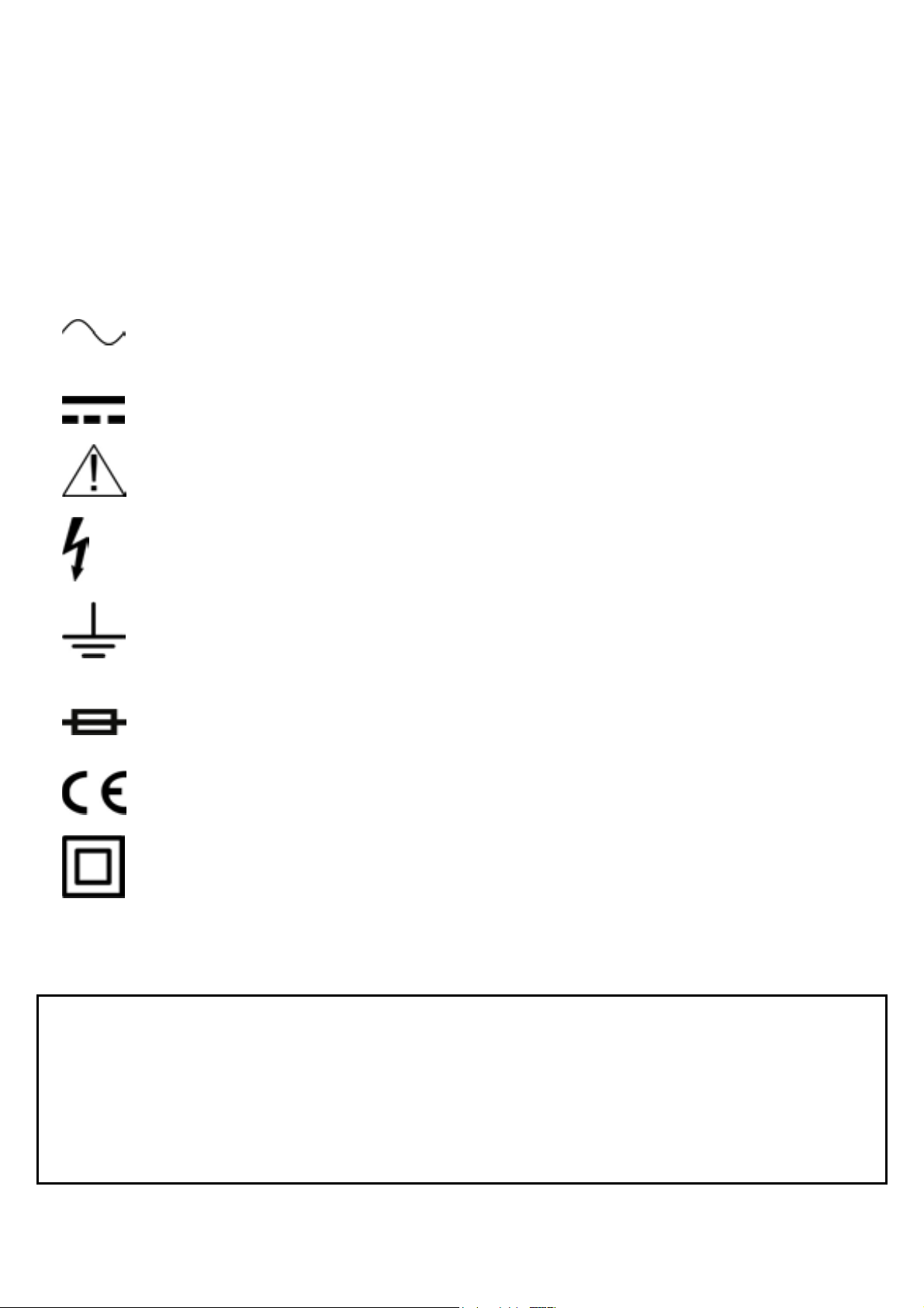
ELECTRICAL SYMBOLS
AC (Alternating Current)
DC (Direct Current)
Important safety information. Refer to the manual.
Dangerous voltage may be present.
Earth ground
Fuse
Conforms to European Union directives
Double insulated
Do not attempt to make any repairs yourself. This would invalid your warranty.
Do not make any changes to the unit. This would also invalid your warranty.
The warranty is not applicable in case of accidents or damages caused by
inappropriate use or disrespect of the warnings contained in this manual.
Mercury cannot be held responsible for personal injuries caused by a
disrespect of the safety recommendations and warnings.
This is also applicable to all damages in whatever form.
Page 4

WARNING
To avoid possible electric shock or personal injury, follow these
guidelines:
• Do not use the meter if it is damaged. Before you use the
meter, inspect the case. Pay particular attention to the
insulation surrounding the connectors
• Inspect the test leads for damaged insulation or exposed
metal. Check the test leads for continuity. Replace damaged
test leads before you use the meter.
• Do not use the meter if it operates abnormally. Protection
may be impaired. When in doubt, have the meter serviced.
• Do not operate the meter around explosive gas, vapour, or
dust.
• Do not apply more than the rated voltage, as marked on the
meter, between terminals or between any terminal and earth
ground.
• Before use, verify the meter's operation by measuring a
known voltage.
• When servicing the meter, use only specified replacement
parts.
• Use with caution when working above 30V AC RMS, 42V
peak, or 60V dc. Such voltages pose a shock hazard.
• When using the probes, keep your fingers behind the finger
guards on the probes.
• Connect the common test lead before you connect the live
test lead. When you disconnect test leads, disconnect the live
test lead first.
• Remove the test leads from the meter before you open the
battery door.
• Do not operate the meter with the battery door or portions of
the cover removed or loosened.
• To avoid false readings, which could lead to possible electric
shock or personal injury, replace the batteries as soon as the
low battery indicator (”
”) appears.
Page 5

FRONT PANEL DESCRIPTION
1. Transformer Jaws
Pick up the AC current flowing through the conductor.
2. “DATA HOLD” Button
A push button for selecting Data Hold function.
3. Function / Range Switch
Function / Range switch for selecting measurement function and
range.
4. Display
3 ½ digits LCD, Max. reading 1999.
5. Drop-proof Wrist Strap:
Prevent the instrument from slipping off the hand while in use.
6. “EXT” Jack
Plug-in connector for the banana plug “EXT” from an external
insulation resistance tester unit.
7. “COM” Jack
Plug-in connector for the black test lead while measuring voltage,
resistance and continuity; and for connecting the banana plug
“COM” from the insulation tester unit while measuring insulation
resistance.
8. V.Ω Input Connector:
Plug-in connector for the red test lead while measuring voltage,
resistance and continuity; and for connecting the banana plug “V.Ω”
from the insulation tester unit while measuring insulation resistance.
9. Trigger
Press the level to open the transformer jaws; when the finger
pressing on the level is released, the jaws will close again.
INTRODUCTION
Page 6
The meter is a portable, 3 ½ digits LCD clamp meter with insulation
test function (with optional 500V insulation tester unit) designed for
being used by electricians, technicians, serviceman and hobbyists
who need an instrument that is accurate, reliable, and always ready
for use. It is powered by a standard 9V battery, and can provide
150-200 operating hours, which depends on the type of battery and
using conditions. It has rugged structure design, good feeling held
in operator’s hand and convenient use.
OPERATING FEATURES
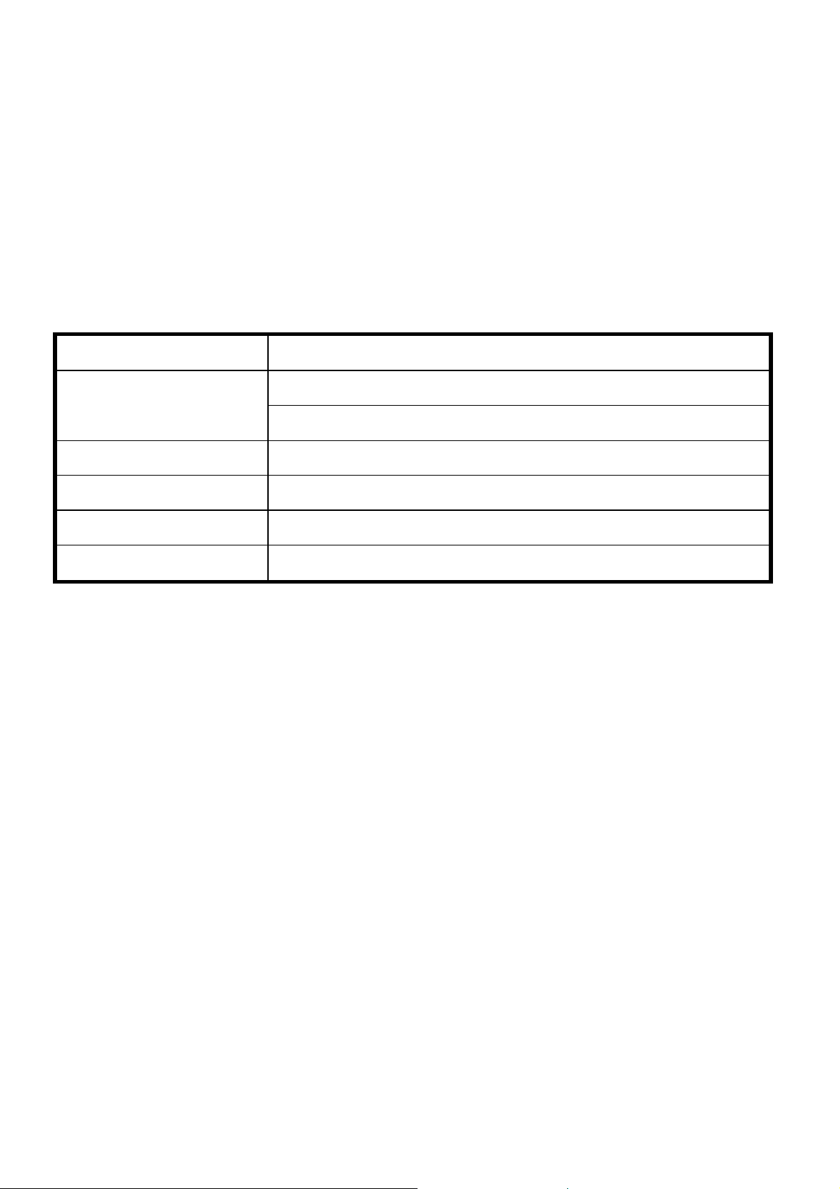
AC Current 200A - 1000A
20MΩ - 2000MΩ
Insulation Test
( With optional 500V insulation tester unit )
AC Volage 750V
DC Volage 1000V
Resistance 200Ω - 20kΩ
Continuity Test <50Ω with audio tone
The display of the meter is liquid crystal assembly providing reliable
and readable display in all light conditions. The decimal point is
automatically positioned, and the polarity sign (minus) is lighted for
negative DC measurement (that no sign appears is defaulted as
positive) so that the display can be read directly while making
measurement. Over-range measurement is indicated by figure "1"
only. In addition, the display includes low battery indication. If low
battery sign is indicated, the operator should replace the exhausted
battery with a new one.
SPECIFICATIONS
The following specifications assume a l-year calibration cycle and
operating conditions of temperature scale of 18ºC to 28ºC (64ºF to
82ºF) with relative humidity up to 80% unless otherwise noted.
Page 7
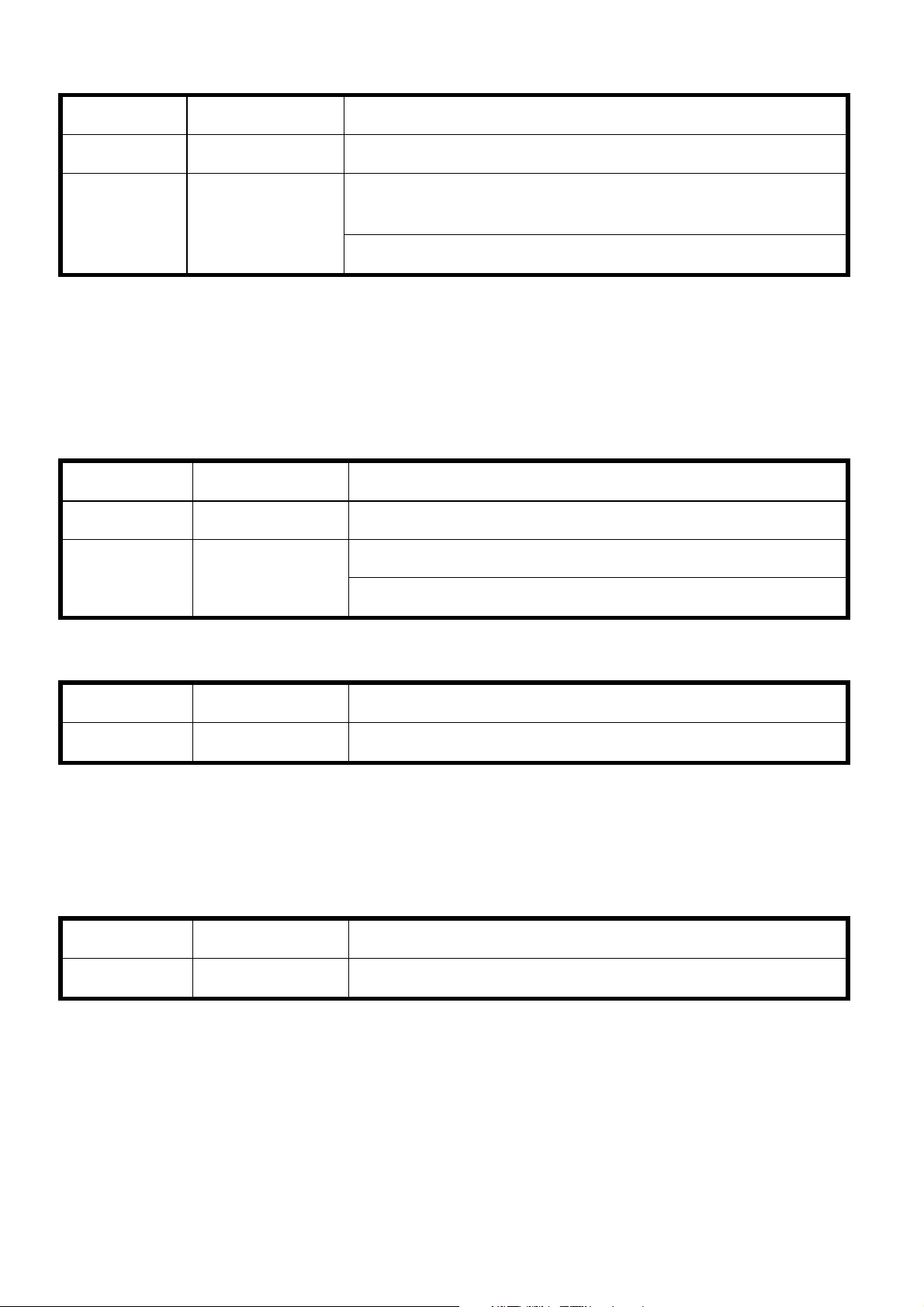
AC Current
Range Resolution Accuracy(50Hz-60HZ)
200A 100mA ±(2.5% of rdg + 8 digits)
±(2.5% of rdg + 5 digits) for 800A and
1000A 1A
below
±(3% of rdg + 5 digits) for other current
Frequency response: 50~60Hz
Indication: Average (rms of sine wave)
Overload protection: 1200A within 60 seconds.
Jaw opening: 2” (5cm)
Insulation Test (with optional 500V insulation tester unit)
Range Resolution Accuracy(50Hz-60HZ)
20MΩ 10K Ω ±(2% of rdg + 2 digits)
±(4% of rdg + 2 digits) for up to 500M Ω
1000M Ω 1M Ω
±(5% of rdg + 2 digits) for above 500M Ω
AC Voltage
Range Resolution Accuracy(50Hz-60HZ)
100s0V 1V ±(2% of rdg + 5 digits)
Indication: Average (rms of sine wave)
Input impedance: 9M Ω
Overload Protection: 750V AC/DC on all ranges.
DC Voltage
Range Resolution Accuracy(50Hz-60HZ)
750V 1V ±(2% of rdg + 5 digits)
Overload Protection: 1000V DC/AC peak on all ranges
Input impedance: 9M Ω
Page 8
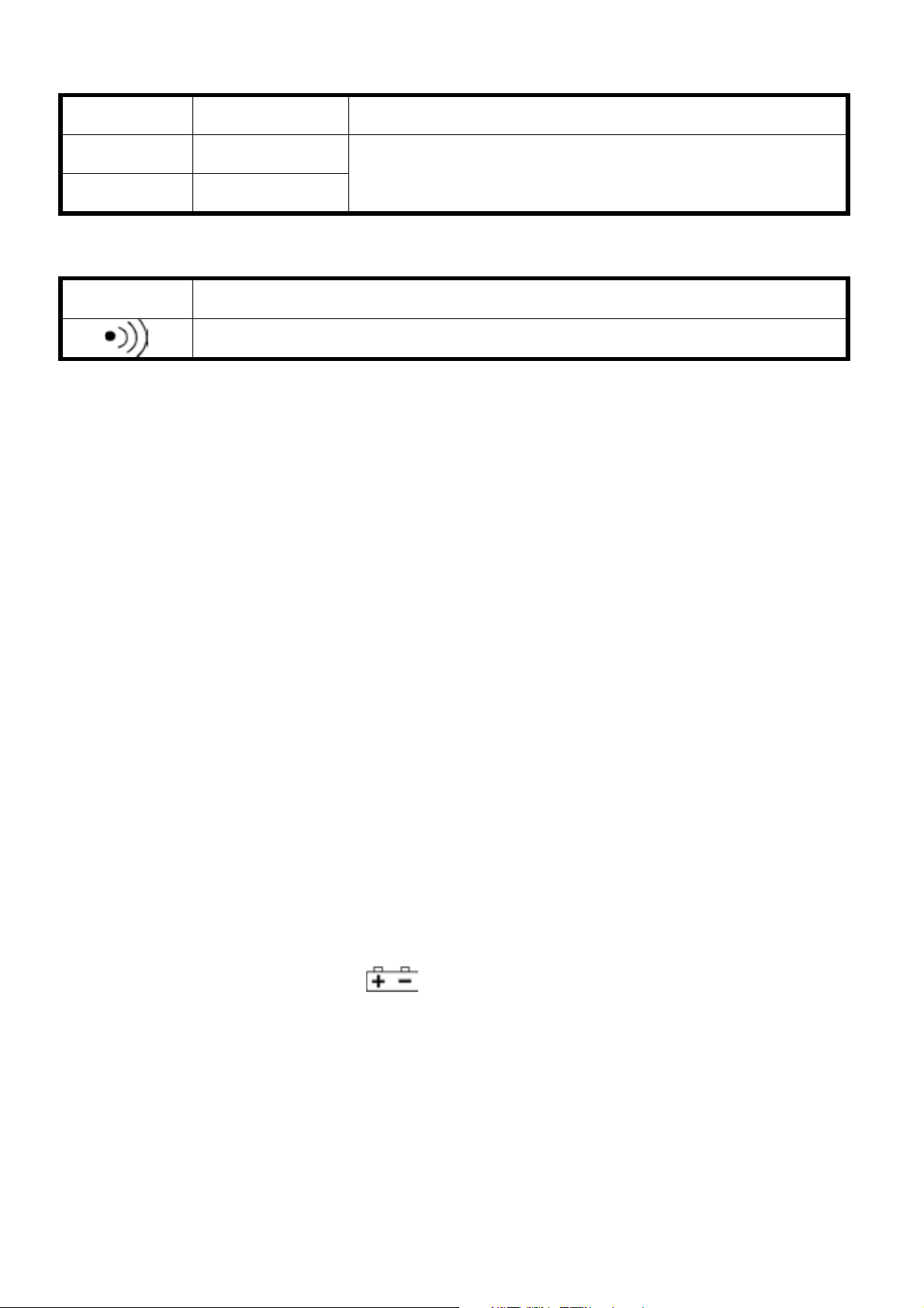
Resistance
Range Resolution Accuracy(50Hz-60HZ)
200Ω 1Ω
±(1.0% of rdg + 2 digits)
20KΩ 10Ω
Continuity Test
Range Accuracy
When the resistance <50Ω, the built-in buzzer will sound.
ENVIRONMENT
Normal operation: 18ºC ~ 28ºC (64ºF ~ 82ºF)
Usable condition: 0ºC ~ 50ºC (32ºF ~ 122ºF)
Storage condition : -20ºC ~ 60ºC (-30ºF ~ 140ºF) with battery
removed and <80% R.H.
Relative Humidity: <80%
FUNCTION CHARACTERISTICS
Measurement method: Dual slope integration A/D converter
Reading rate: 3 times/second
Polarity:
Automatic polarity indication, “-“ displayed for negative polarity
Overload indication: Only figure “1” on the LCD.
Power supply: 9V 6F22
Battery life: up to 200 hours (for Zinc carbon).
Low battery indication: “
” displayed on the LCD when
approximately 20% of battery life remains.
Display: 3-1/2 digits LCD (1999 count, 0.5” high).
Data hold:
Current reading will be held on the LCD if the button is pressed.
Dimension: 9”L x 2.7”W x 1.5”H (123cm x 7cm x 3.7cm)
Weight: about 11 ounces (310 grams) (including battery)
Page 9

Accessories
Instruction manual: 1 copy
Test leads: 1 pair
9V Zinc carbon battery: 1 piece
Carrying Case: 1 piece
OPERATING INSTRUCTION
AC Current Measurement
1) Make sure the "Data Hold" switch is not pressed.
2) Set the Function / Range Switch to the required ACA range.
3) Press the trigger to open the transformer jaws and clamp
one conductor only. It is impossible to make measurements
when two or three conductors are clamped at the same time.
4) The value displayed on the LCD is the AC current flowing
through the conductor.
Insulation Resistance Test
1) Set the Function / Range Switch to the insulation tester
2000MΩ range. In this condition, it is normal that the reading
is unstable.
2) Insert the three banana plugs V.Ω, COM, EXT from the
insulation tester unit to the corresponding V.Ω, COM, EXT
input jacks on the clamp meter.
3) Set the Function / Range switch of the insulation tester unit
to the 2000MΩ position.
4) Connect the test leads from the insulation tester unit to the
appliance to be tested (the LED on the insulation tester unit
will light).
5) Set the insulation tester Power switch to the "ON" position.
6) Push the "PUSH-500V" button, the red LED "500V" will light.
The reading on the LCD of the clamp meter is the insulation
resistance value; if the reading is below 19MΩ, set the rotary
switch to range 200MΩ to increase the accuracy of the
measurement.
7) If the insulation tester unit is not used, the power switch must
set to OFF position. And the test leads must be removed
from the input jacks; this can extend the battery life and
prevent electrical shock hazard.
Page 10

DC Voltage measurement
1) Connect the red test lead to the "V.Ω" jack and the black test
lead to the "COM" jack.
2) Set the Function / Range switch to the required DCV range.
If the voltage to be measured is not known beforehand, set
the Function and Range switch to the highest range and
then turn down range by range until satisfactory resolution is
obtained.
3) Connect the test leads to the source or load to be measured.
4) Read the voltage value displayed on the LCD along with the
polarity of the red test lead.
AC Voltage measurement
1) Connect the red test lead to the "V.Ω" jack and the black test
lead to the "COM" jack.
2) Set the Function / Range switch to the required ACV range.
If the voltage to be measured is not known beforehand, set
the Function Range switch to the highest range and then
turn down range by range until satisfactory resolution is
obtained.
3) Connect the test leads to the source or load to be measured.
4) Read the voltage value displayed on the LCD.
Resistance Measurement
1) Connect the red test lead to the "V.Ω" jack and the black test
lead to the "COM" jack.
2) Set the Function / Range switch to the required Ω range.
3) Connect the test leads to the resistor to be measured and
read the value displayed on the LCD.
Note: For resistance about 1MΩ and above, the meter may take a
few seconds to stabilize. This is normal for high resistance
readings.
Page 11

Audible Continuity Test
1) Connect the red test lead to the "V.Ω"and the black test lead
to the "COM" jack.
2) Set the Function / Range switch to "
" range.
3) Connect the test leads to the two terminals of the circuit to
be tested. If the resistance is less than about 50Ω, the builtin buzzer will sound.
 Loading...