

Skytrak SK2-1001-M, SK2-1001-D, SK2-1001-R Installation, Operation & Maintenance Manual
IOM-SK2-1001, Rev. 03 1 of 4
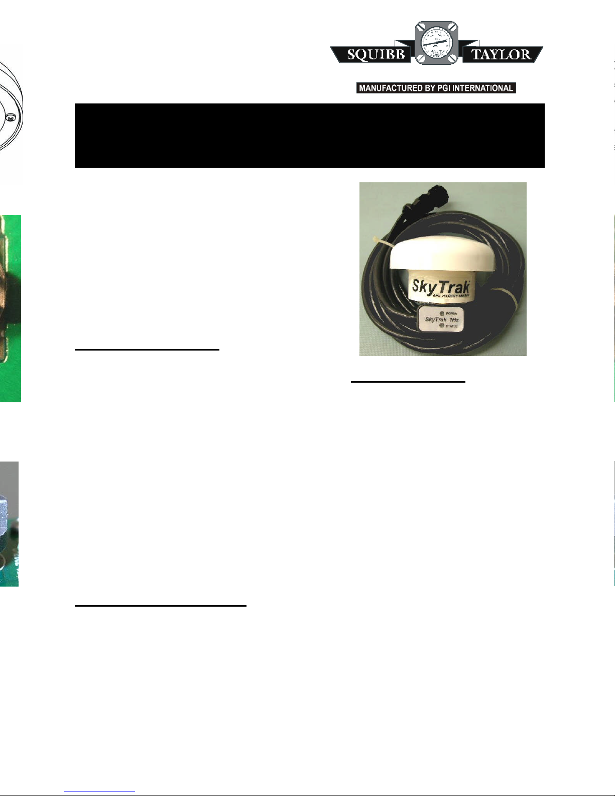
SkyTrak
GPS VELOCITY SENSOR
TM
INCORPORATED
DALLAS TEXAS
(214) 3
57-4591(800)345-810
5
Installation, Operation & Maintenance Manual for Models
SK2-1001-D, SK2-1001-M, & SK2-1001-R
1 Hertz GPS Velocity Sensors
Form IOM-SK2-1001, Rev.03
SkyTrak is a GPS based velocity sensor that
produces true ground speed pulses to equipment
designed to interface with radar ground speed and
wheel speed sensors. SkyTrak can be quickly
transferred from vehicle to vehicle, provides high
accuracy, and is easy to install and use. Simply
make the connection to your monitor/control
equipment, perform the same calibration you would
use for other pulse sensors, and you’re ready to go.
Standard Features
Low cost alternative to radar type
speed sensors
Completely self-contained (GPS,
antenna, and velocity-to-pulse
converter)
16 Channel GPS receiver
Battery backup for GPS satellite
table reduces startup time
Selectable output pulse rates
ensures monitor compatibility
0.1 MPH accuracy from 0.5 to 50
MPH
UV stable, polycarbonate
enclosure
Magnet mount simplifies
installation
Diagnostics LED’s built into the
cable help to quickly verify
performance
Consistent pulses/foot output from
unit to unit
Physical Specifications
Size 3.50” Diameter x 2.14” High
Cable Length 15 feet
Power 4.8 to 16 Volts, 0.1 Amps max.
Backup Battery CR2032 Lithium Coin Cell
Connector DICKEY-john®, Raven, or
Micro-Trak
®
(depending on Model Number)
Operating Temp. -30°C to +65°C
(-22°F to +149°F)
Storage Temp. -40°C to +80°C
(-40°F to +176°F)
Humidity 100% Condensing
Performance Specifications
Velocity Accuracy 0.1 MPH (without SA)
GPS Update Rate 1 Hz.
Backup Battery Life > 3 years
Acquisition Rate
Cold Start < 52 seconds
Warm Start < 9 seconds

2 of 4 IOM-SK2-1001, Rev. 03
Mounting Considerations
The SkyTrak mounting location should have a clear view of satellites on all sides.
The SkyTrak unit must be mounted with the dome pointing to the sky.
Avoid overhead metal structures that can block the satellite signals.
Avoid mounting in areas with excessive vibration. An antenna that moves or sways may
produce ground speed errors. The idea is to have the antenna move only when the vehicle is
moving for accurate true ground speed measurement.
To protect against dirt and debris entering the interior of the unit, avoid mounting in
locations close to the ground.
Make sure the cable can be safely routed to the connection point.
SkyTrak can be mounted on a flat surface such as the roof of the vehicle cab.
Position the SkyTrak status indicator so that it is easily viewable.
Power Supply Warnings:
DICKEY-john
®
A DICKEY-john®unit cannot be used in Raven applications by using a pin-for-pin adapter.
Many Raven devices do not supply adequate power to operate the SkyTrak directly.
Therefore, a Raven specific connector must be supplied which provides for connection of an
independent 12 volt power source to the SkyTrak. The SkyTrak model SK2-1001-R provides
the necessary power connection for Raven applications.
It is also very important that a good ground is provided through the connector.
Raven
SkyTrak requires 4.8 to 16 volts at about 0.1 amps to operate. Although the Raven controller
speed sensor interface connector provides 5 volts and ground to power some radar guns, it
does not supply enough power for the SkyTrak sensor. SkyTrak power must be supplied
separately. The positive lead of the SkyTrak power should be connected to the blue lead at
the connector end of the SkyTrak harness. To simplify installation, a 1-pin crimp-on
connector is provided. Using the connector will also make it easy to unplug the SkyTrak if it
needs to be removed. Ground, or the power minus connection, is provided through the
controller's speed sensor interface connector which must be a proper ground. Choose a
power source that is fused and switches off when the tractor is off.
Separate Power Lead
(see Power Supply Warnings: Raven)
IOM-SK2-1001, Rev. 03 3 of 4
Calibration
After installing SkyTrak, your control equipment will need to be calibrated. Follow the calibra-
tion procedure for your controller or monitor as if you were using a radar or wheel speed sensor.
Typically, this involves driving an accurately measured distance to determine a speed cal value
for your system.
Before running the calibration, allow the SkyTrak to download a full satellite table by turning on
SkyTrak where it has a clear view of the sky for about ten minutes. The status indicator should be
solid green (using 4 or more satellites) before performing the calibration.
Backup Battery Replacement
The backup battery should be replaced every three years. If the status indicator takes several
minutes to switch to green when the unit is powered up after it has been off for only a short time,
this is an indication that the battery needs to be replaced. To gain access to the battery, see the
Maintenance section in this manual.
Selecting the Pulse Output Rate
The pulse rate for the SkyTrak is factory set to 58.94 PPS (pulses per second) / MPH (mile per
hour). This setting will be suitable for most applications. If your application requires a different
rate, a small jumper under the SkyTrak cover allows the pulse output rate to be changed.
Available rates are...
Position 1 58.94 PPS/MPH — 40.1864 pulses/foot
(Factory setting for most models)
Position 2 44.21 PPS/MPH — 30.1432 pulses/foot
Position 3 Reserved
Position 4 Reserved
Position 5 9.823 PPS/MPH — 6.6975 pulses/foot
(Factory setting for Micro-Trak
The 58.94 PPS/MPH setting is shown here, with the
jumper installed horizontally for Position 1.
(Position 1 is the same as having no jumper installed.)
For Positions 2, 3, 4, & 5, the jumper must be installed
vertically, in line with the corresponding Position
Number. To gain access to the jumper, see the Maintenance section in this manual.
Status LED Operation
The SkyTrak power indicator will be on GREEN as long as power is applied to the unit.
When power is first applied, the SkyTrak status LED will FLASH GREEN to indicate the pulse
output jumper position. For example, if the jumper is in position 2, (to achieve the 44.21 PPS/
MPH rate), the status LED will FLASH GREEN two times.
While the SkyTrak GPS receiver is building the GPS satellite table, the status LED will be RED.
The startup time depends on how long the unit has been off but is less than 45 seconds. The
internal backup battery allows the GPS to keep the satellite table, even while SkyTrak is off.
This can significantly speed up the start up time since the table does not need to be completely
loaded - just updated.
When the GPS is ready, the status LED will go from RED to GREEN (if the vehicle is stopped).
When the vehicle is moving, the status LED will begin flashing between RED and GREEN at
the output pulse rate after the GPS is ready. Usually the flashing status LED is so fast that it
appears as though both the red and green are on at the same time.
If the GPS loses the satellite signal, the status LED will go solid RED (even if the vehicle is
moving) until a good signal is re-acquired.
If the GPS is healthy, the status LED will be GREEN when the vehicle is stopped.
 Loading...