


Keep this manual with the vehicle at all times.
8990504
OWNERS/OPERATORS
MANUAL
Model MMV
(S/N MV201 & After)
(Tier 2)
OM0652
TM 10794B-12/1
Printed in U.S
.A. 10/11
PCN 500 107943 00

WARNING: Improper operation of this vehicle can
CALIFORNIA
Proposition 65 Warning
Diesel Engine exhaust and some of its constituents
are known to the State of California to cause
cancer, birth defects and other reproductive harm.
CALIFORNIA
Proposition 65 Warning
Battery posts, terminals and related accessories
contain lead and lead compounds, chemicals
known to the State of California to cause cancer
and birth defects or other reproductive harm.
Wash hands after handling
.
cause injury or death. Only trained and authorized operators
should operate this vehicle.
Before starting the engine, do the following:
1. Read this owner/operators manual.
2. Read all the safety decals on the vehicl e.
3. Clear the area of other persons.
Learn and practice safe use of vehicle controls in a safe,
clear area before you operate this vehicle on a worksite.
It is your responsibility to observe applicable laws and
regulations and to follow manufacturer's instructions on
vehicle operation and maintenance.

Revision Log
Revision Log
December 17, 2004 - B - Replaced all branding with JLG.
October 12, 2011 - C - Revised pages 22, 27, 66, 67, 70, 157, 170, 171, 182 thru
185, 193, 201, 218, 219, 221, 222 & 246.
REVISION LOG
8990504
a

Revision Log
b
8990504

Table of Contents
Revision Log
Introduction
The Manual....................................2
Replacement Parts........................2
Reports..........................................2
Disclaimer......................................3
Safety Practices
Hazard Classification System........3
Accident Prevention Tags..............5
New or Additional Operators .........5
Instructional Symbols ....................6
Hazard Symbols............................7
Avoidance Symbols.......................8
Avoidance Symbols (cont’d)..........9
Personal Considerations .............10
Operational Considerations.........14
Equipment Considerations ..........20
Operation
Operator Controls........................23
Front Dash Panel.........................54
Instruments and Indicators..........61
Pre-Operation Inspection.............66
Normal Starting............................67
Cold Starting................................68
Slave Starting..............................70
Refueling .....................................71
Operating.....................................73
Carriages.....................................84
Using the Capacity Chart.............92
Load Capacity To Travel
Speed Tables ...........................94
Fork Rating................................104
How To Pick, Carry & Place
A Load.................... ... .............105
Elevating Personnel...................107
Shut-Off.....................................113
Emergency Operations
Towing a Disabled Vehicle........114
Emergency Boom Lowering ......123
General Maintenance
Introduction................................137
Maintenance Schedule and
Checklist.................................138
1. Lubrication Points ................141
2. Air Cleaner...........................143
3.Closed Cab Air Filters...........147
4.Engine Cooling System ........148
5.Engine Oil and Filter .............152
6.Engine Fuel System..............157
7.Engine Fan Belt....................162
8.Air Conditioner
Compressor Belt ...............163
9.Hydraulic Oil and Filter .........164
10.Transmission Oil
and Filter...........................169
11.Axle Oil ...............................172
12.Brake Disk Inspection.........175
13.Wheel End Oil.....................179
14.Transfer Case Oil................182
15.Wheels and Tires................186
16.Emergency Tire
Inflation System.................188
17.Batteries..............................192
18.Fuse & Relay
Replacement.....................194
19.Boom Chains and
Wear Pads ........................203
Storage and Transport ..............218
Short Term Storage...................218
Long Term Storage...................220
Counterweight Removal
and Reassembly.....................223
Transport...................................226
Test Procedures
Stabil-TRAK™ System Test ......236
Parking Brake/Transmission
De-Clutch
Test Procedures.....................241
Four Wheel Steer Indexing
Procedure...............................244
Specifications
Fluid & Lubrication Capacities...245
Tires .......................................... 247
Weights .....................................248
Vehicle Dimensions...................249
Electrical System.......................250
Engine.......................................252
Index.............................................255
Accident Prevention Tags
Replacement Manuals...................1
This document has been prepared by JLG Industries Inc. for the USMC, 2004.
Approved for public release; distribution is unlimited.
1
Introduction
OM1370
1
Introduction
The Manual
This Owners/Operators Manual provides the information you need to
operate and maintain this vehicle.
IMPORTANT! Before
and carefully so you will understand the instructions and the operation of
the controls and equipment. You must comply with all Danger, Warning,
and Caution notices; they are for your benefit.
All references to the right side, left side, front, or rear are given from the
operator's seat looking forward.
you operate this vehicle, read this manual completely
Replacement Parts
For easy reference when ordering
replacement parts or making service
inquiries on this vehicle, record its
model and serial number on the back
cover of this manual. The serial
number is stamped into the serial
number plate (1) which is located on
the vehicle’s frame.
IMPORTANT! The re pla ce m en t of
any part on this vehicle by anything
other than a JLG authorized
replacement part may adversely
affect the performance, durability or
safety of this vehicle and may void the warranty. JLG assumes no liability
for unauthorized replacement parts which adve rsely affect the perfo rmance,
durability or safety of this vehicle.
Reports
IMPORTANT! A Warranty Registration form must be filled out by the JLG
Authorized Service Center (ASC), signed by the purchaser, and returned to
JLG once the product is sold and/or put into service. This report activates
the warranty period, assuring that your claims during the warranty period
will be processed promptly. To guarantee full warranty service, make sure
your Authorized Service Center (ASC) has returned th e business reply card
of this form to JLG.
2
Model MMV Rev. 10/11
Safety Practices
OP0330
Disclaimer
JLG reserves the right to make changes on and to add improvements upon
its products at any time without public notice or obligation. JLG also
reserves the right to discontinue manufacturing any product at its d iscretion
at any time.
NOTICE: Under OSHA rules, it is the responsibility of the employer to
provide operator training. Successful completion and certification of Safety
Training for Rough Terrain Forklifts is required. Operator Training Kits are
available by calling Ken Cook Company at (414) 466-6060. An order form
for these kits is available through our website,
http://www.jlg.com.
The information in this manual does not replace any safety rules and laws
used in your area. Before operating this vehicle, learn the rules and laws for
your area. Make sure the vehicle has the correct equipment according to
these rules and laws.
Your safety and the safety of others in the worksite depend significantly
upon your knowlege and understanding of all correct operatin g practices
and procedures for this vehicle.
WARNING: DO NOT modify or alter (weld, drill, etc.)
any part of this vehicle without consulting JLG. Modifications can
weaken the structure creating a hazard that can cause death or
serious personal injury.
Safety Practices
Hazard Classification System
This safety alert symbol is used with the following signal words to attract
your attention to messages found within the manual and on hazard decals
located on the vehicle. They are reproduced herein and pertain to proper
operation and procedure messages contained throughout the manual. The
message that follows the symbol contains important information about
Safety. To avoid possible death or serious personal injury, carefully read
and follow the messages! Be sure to fully understand the potential causes
of death or injury.
Model MMV Rev. 10/11
3
Safety Practices
Signal Word
A signal word is a distinctive word located on hazard decals and used
throughout this manual that alerts the viewer to the e xistence of and relative
degree of the hazard.
DANGER:
The signal word “DANGER” indicates an imminently hazardous situation
which, if not avoided, will result in death or serious personal injury.
WARNING:
The signal word “WARNING” indica tes a potentially hazardous situation
which, if not avoided, could result in death or serious personal injury.
CAUTION:
The signal word “CAUTION” indicates a potentially hazardous situation
which, if not avoided, may result in minor or moderate injury.
CAUTION:
The signal word “CAUTION”, used without the safety alert symbol, indicates
a potentially hazardous situation which, if not avoided, may result in
property damage.
For safe maintenance of the vehicle, read, understand and follow all
DANGER, WARNING and CAUTION information.
4
Model MMV Rev. 10/11
Safety Practices
DANGER
DANGER
OM1750
1
2
3
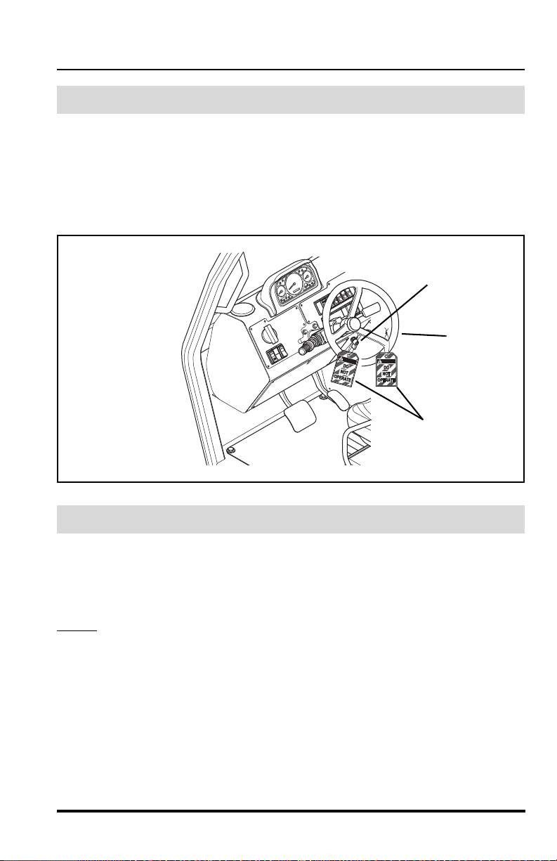
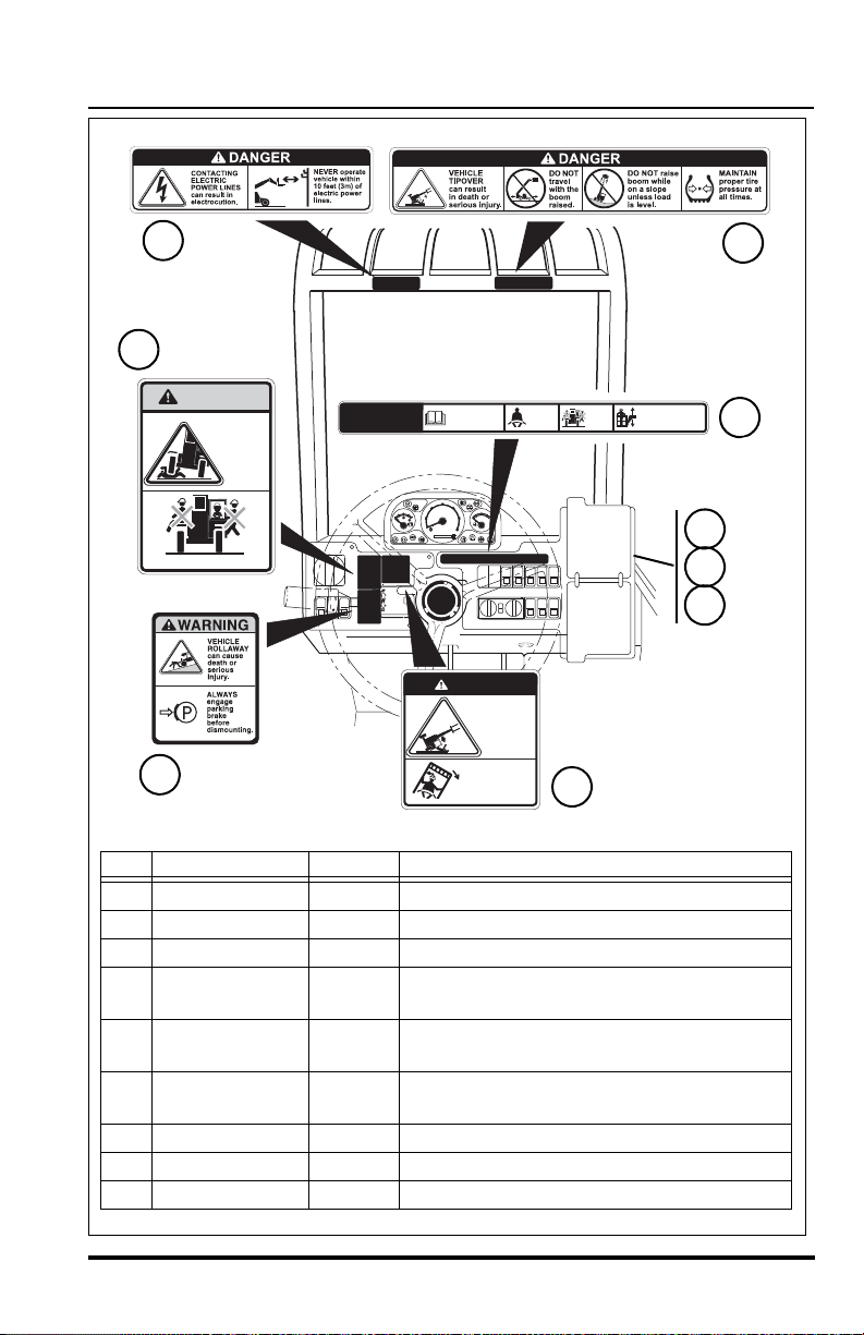
Accident Prevention Tags
Before beginning any maintenance or service, place an Accident
Prevention Tag (1) on both the ignition switch (2) and t he steering wheel (3),
stating that the vehicle should not be operated. Actual Accident Prevention
Tags, which can be punched out and used, are included as the last page of
this manual. Retain these Accident Prevention Tags for reuse at a later
date.
New or Additional Operators
At the time of original purchase, the purchaser of this vehicle was instruct ed
by the seller on its proper use. If this vehicle is to be used by an employee
or is loaned or rented to someone other than the purchaser, make certain
that the new operator is trained, in accordance with the OSHA re gu la tio ns
referenced on page 3, and reads and understands this Operators Manual
before
operating the vehicle.
In addition, make sure that the new operat or has completed a walk-around
inspection of the vehicle, is familiar with all decals on the vehicle, and has
demonstrated the correct use of all controls.
Model MMV Rev. 10/11
5

Safety Practices
OP0330
OH2100
OH2090
Safety Alert Symbol
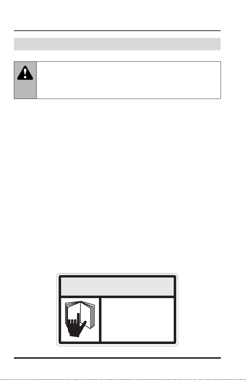
Read Operator’s Manual
Fasten Seat Belt
Instructional Symbols
The following symbol definitions will help you understand all hazard
related decals used on this vehicle.
6
Model MMV Rev. 10/11

Hazard Symbols
-
OH2110
Lead Acid Batteries
Generate Explosive Gases
OH2120
OH2300
OH2161
OH2130
OH2140
OH2150
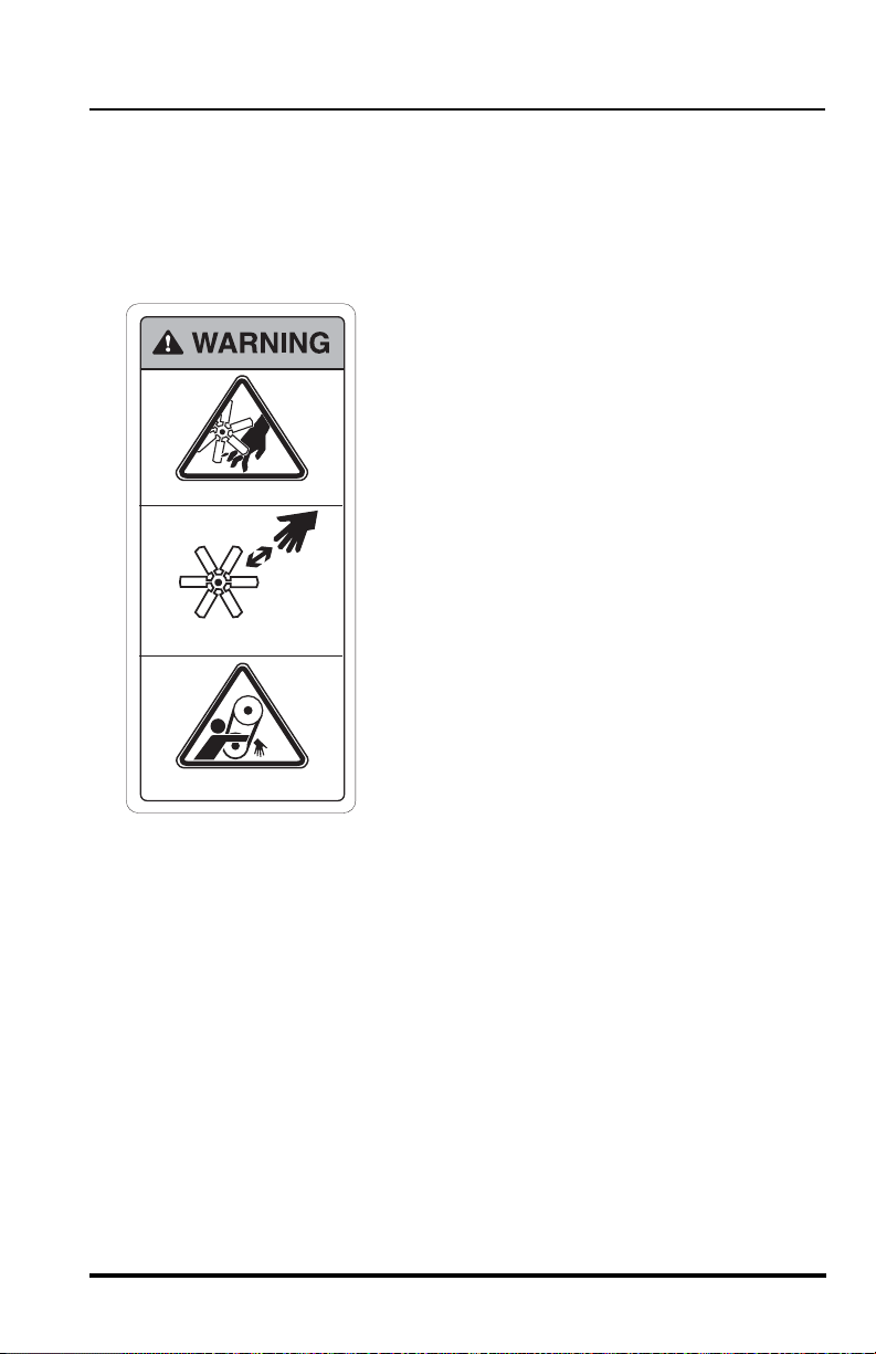
Rotating Fan Blades
Can Cut
Rotating Belts Can Cut
Or Entangle
Vehicle Tipover Can
Crush
Vehicle Roll Away Can Cause
Death Or Serious Injury
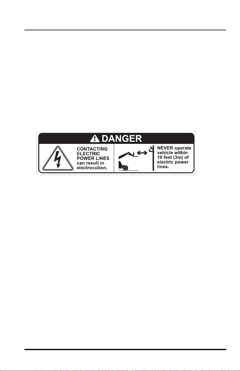
Electrocution Can
Cause Death Or
Serious Injury
FALLING OFF ATTACHMENT
Can Result In Death Or Serious
Injury
OH3160
OU1450
ENGINE EXPLOSION
Can Result In Death
Or Serious Injury
AVOID CRUSHING, Falling Off
Vehicle Can Cause Death Or
Serious Injury
Safety Practices
Model MMV Rev. 10/11
7
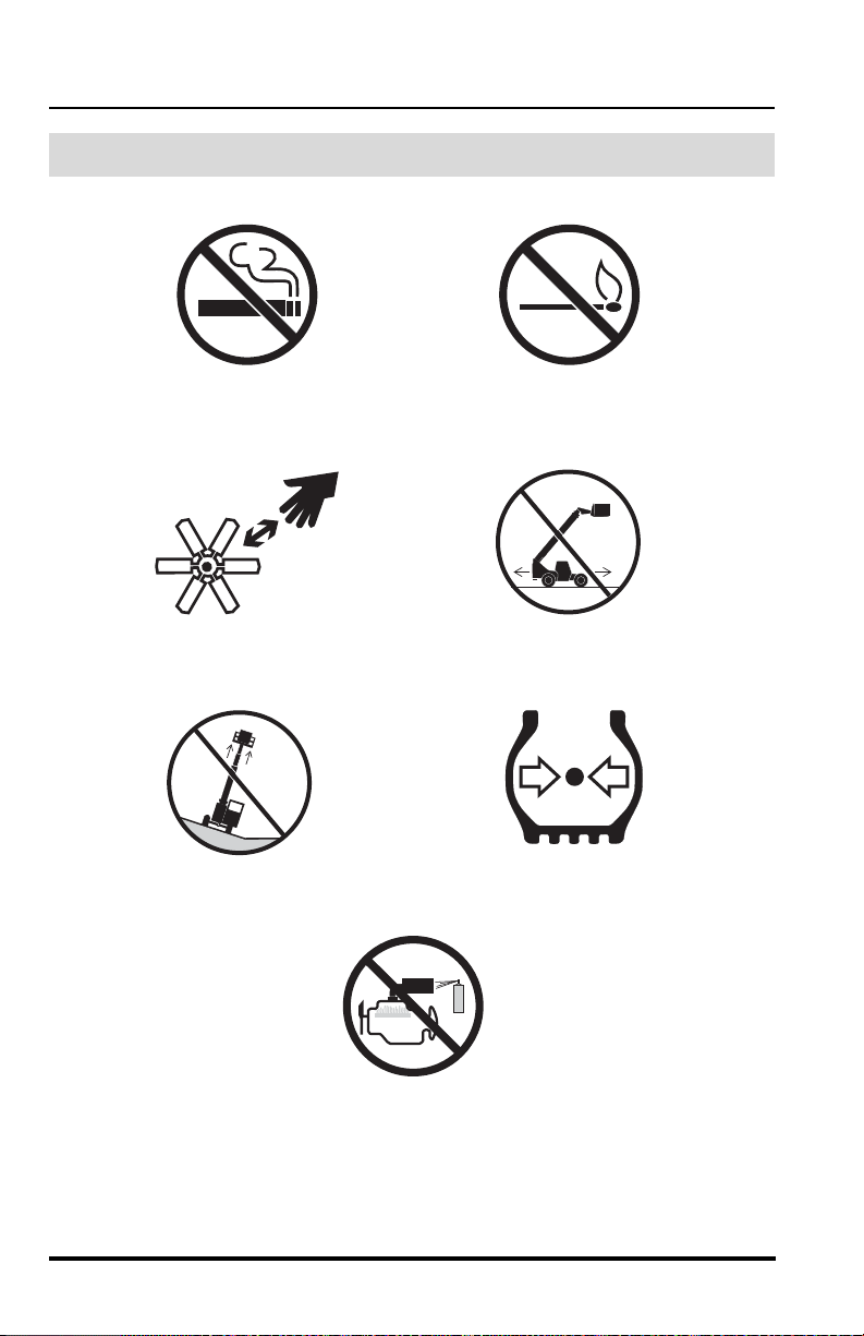
Safety Practices
OH2320
Keep Lit Cigarettes
Away
OH2310
OH2280
OH2330
OH2270
OH2290
Keep Away From
Rotating Fan Blades
Do Not Raise Boom
While On A Slope
Keep Flames and
Ignition Sources Away
Do Not Travel With
Boom Raised
Maintain Proper Air
Pressure In Tire
OU1460
DO NOT Use Ether Or
Other High Energy
Starting Aids.
Engine Equipped With
Grid Heating System.
Avoidance Symbols
8
Model MMV Rev. 10/11

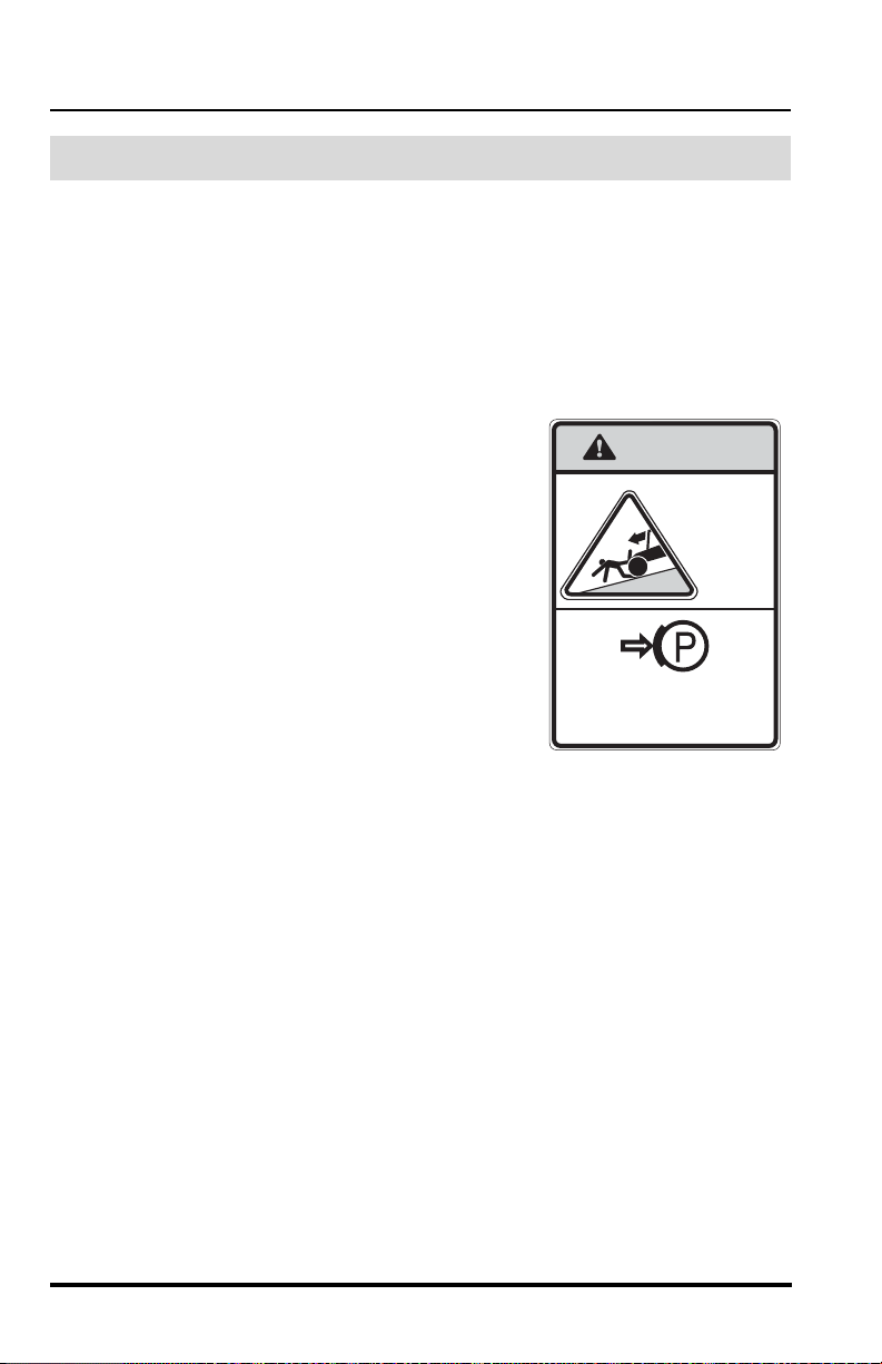
Safety Practices
OH2260
Engage Parking Brake
OH2240
OH2220
OH2250
OH2230
OH2170
Do Not Travel With
Personnel In Work
Platform
DO NOT JUMP
Keep Clear Of Power
Lines
Carry No Riders
Use Only Compliant
Work Platforms To
Raise Or Lower
Personnel
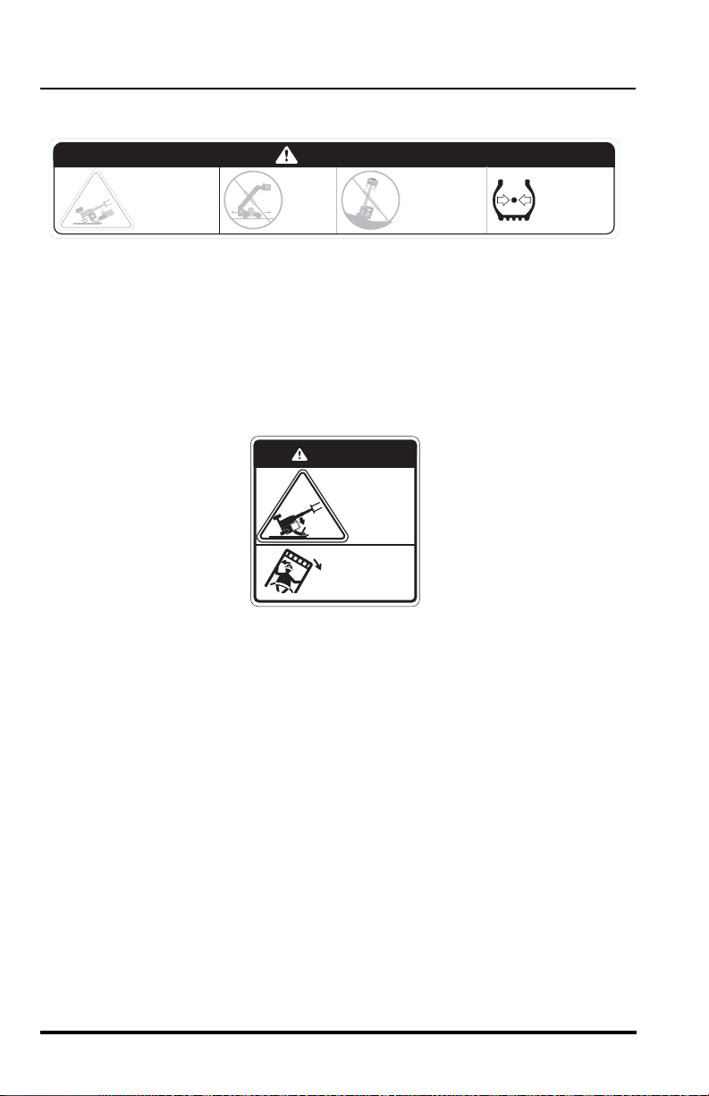
• Brace Yourself and Stay
With Vehicle
• Keep Seat Belt Fastened
• Hold On Firmly
• Lean Away From The
Point Of Impact
Avoidance Symbols (cont’d)
Model MMV Rev. 10/11
9
Safety Practices
ALWAYS
engage parking brake
before dismounting
WARNING
VEHICLE
ROL LAWAY
can cause
death or
serious
injury
OU0340
Personal Considerations
1. Seat Belt
Always fasten the seat belt before starting the engine.
2. Clothing and Safety Gear
DO NOT wear loose clothing or jewelry that can get caught on controls
or moving parts. Wear protective clothing and personal safety gear
issued or called for by job conditions.
3. Dismounting
DO NOT get off the vehicle until you:
• level the vehicle,
• ground the carriage,
• place the travel select lever in (N)
NEUTRAL,
• place the neutral lock lever in (N)
NEUTRAL LOCK,
• engage the parking brake switch,
• turn the engine off, if appropriate,
• unbuckle the seat belt,
• exit the vehicle using the hand holds.
4. Chemical Hazards
A. Exhaust Fumes
Fumes from the engine exhaust can cause death or serious
personal injury. DO NOT operate vehicle in an enclosed area
without a ventilation system capable of routing the hazard ous
fumes outdoors.
B. Explosive Fuel
Engine fuel is flammable and can cause a fire and/or an explosion.
Avoid danger by keeping sparks, open flames and smoking
materials away from the vehicle and from fuel during refueling or
when servicing the fuel system. Know where fire extinguishers are
kept on the worksite and how to use them.
10
Model MMV Rev. 10/11
Safety Practices
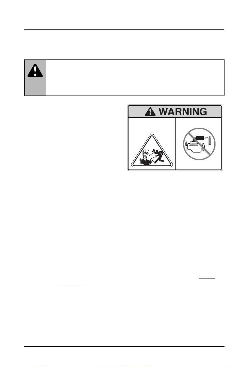
4110460
ENGINE EXPLOSION can
result in death or serious
personal injury.
DO NOT use Ether or other
high energy starting aids.
Engine equipped with
grid heating system.
OU1470
C. Ether or High Energy Starting Aids
The engine utilizes a grid heating system inside the induction
manifold for cold starting conditions.
WARNING: This diesel engine uses a grid heating sys-
tem inside the induction manifold. DO NOT use ether or any high
energy fuels to assist starting. An explosion may cause death or
serious personal injury or engine damage.
DO NOT use ether or any
other high energy starting
aids during cold starting. An
engine explosion can result
in death or serious personal
injury.
D. Hydraulic Fluid
DO NOT attempt to repair or tighten any hydraulic hoses or fittings
while the engine is running or when the hydraulic system is under
pressure. Fluid in the hydraulic system is under enough pressure
that it can penetrate the skin causing death or serious personal
injuries.
Model MMV Rev. 10/11
HOT HYDRAULIC FLUID WILL CAUSE SEVERE BURNS. Wait
for fluid to cool down before disconnecting lines.
DO NOT use your hand to check for leaks. Use a piece of
cardboard or paper to search for leaks. Wear gloves to protect
hands from spraying fluid.
Hydraulic fluid can cause permanent eye injury. Wear appropriate
eye protection and stop engine. Relieve pressure before
disconnecting lines. Pressure can typically be relieved by slowly
and cautiously
loosening one end of a hose at the swivel
connection.
If anyone is injured by or if any hydraulic fluid is injected into the
skin, obtain medical attention immediately or gangrene may result.
11
Safety Practices
-
OS0621
Battery Electrolyte First Aid:
• External Contact — Flush with water.
• Eyes — Flush with water for at least 15 minutes and
get medical attention immediately
.
• Internal Contact — Drink large quantities of water. Follow
with Milk of Magnesia, beaten egg or vegetable oil.
Get medical attention immediately
.
IMPORTANT! In case of internal contact, DO NOT give fluids that
would induce vomiting!
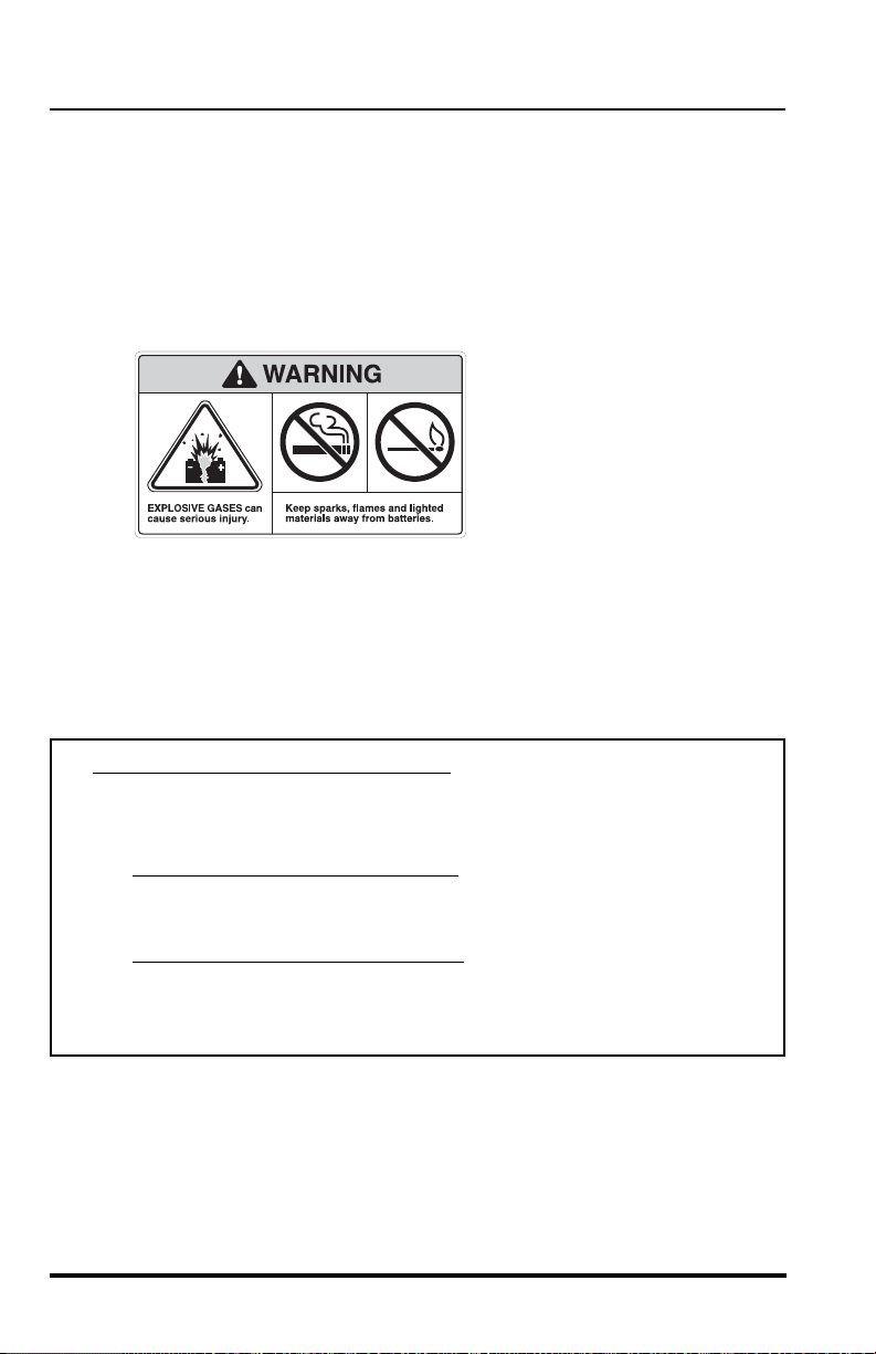
E. Batteries
The following WARNING is intended to supplement and does not
replace the warnings and information provided on the batteries by
the battery manufacturer.
When slave starting the vehicle, carefully follow instruction s f ound
under “Slave Starting” on page 70.
Keep sparks, flames and lit smoking materials away from the
batteries at all times. Lead acid batteries generate explosive
gases. Severe chemical burns can result from improper handling of
battery electrolyte. Wear safety glasses and proper protective gear
when handling batteries to prevent electrolyte from coming in
contact with eyes, skin or clothing.
12
Model MMV Rev. 10/11
Safety Practices
MOVING PARTS can cut.
Keep clear of fan and belts
while engine is running.
MOVING PARTS can entangle.
OT0810
5. Moving Parts Hazard
DO NOT place limbs near moving parts. Severing of any body part can
result.
Turn of f engine and wait until fan and belts stop moving before
servicing.
6. Lowering Boom or Falling Load Hazard
DO NOT get under a raised boom unless it is blocked up sa fely. Always
empty the attachment of any load and block the boom up before doing
any servicing that would require the boom to be raised.
NEVER allow anyone to walk or stand under the boom. A lowering
boom or falling load can result in death or serious personal injury.
Model MMV Rev. 10/11
13

Safety Practices
Operational Considerations
1. Preparation and Prevention
Know the location and function of all vehicle controls.
Make sure all persons are away from the vehicle and that the travel
select lever is in the (N) NEUTRAL position and the Neutral Lock Lever
is in the (N) NEUTRAL LOCK position with the parking brake switch
engaged before starting the engine.
Holes, obstructions, debris and other worksite hazard s can cause death
or serious personal injury. Always walk around and look for these and
other hazards before operating the vehicle in a new worksite.
Prevent accidents when you move the vehicle around the worksite.
Know the rules for movement of people and vehicles on the worksite.
Have a person act as a lookout for you. Follow the instructions of
signals and signs.
DO NOT operate the vehicle unless all hazard and instructional decals
are in place and readable. (Replace all missing, illegible, or damaged
decals.)
2. Clearances
Look out for and avoid other personnel, machiner y and vehicles in the
area. Use a spotter if you do not have a clear view of conditions that
affect clearances. Travel with the boom fully retracted and lowered as
far as possible while still maintaining enough ground clearance for
conditions.
Always check boom clearances carefully before driving underneath
door openings, bridges, etc.
Always check for power lines when raising the boom. Beware of
overhead wires. Contact with electrical power lines can result in
electrocution. See “Electrocution Hazards” on page 15.
3. Visual Obstruction
Dust, smoke, fog, etc. can decrease vision and cause an accident.
Always stop or slow the vehicle until the obstruction clears and the
worksite is visible again. Have a lookout person assist you.
Where the load will obstruct the operator’s vision, it is recommended
that the vehicle be operated in REVERSE, looking backwards in the
direction of travel. Travel at a slower speed and get someone to direct
you.
14
Model MMV Rev. 10/11
Safety Practices
OS0063
4. Underground Hazards
Know the location of all underground hazards before operating this
vehicle in a new area or worksite. Electrical cables, ga s an d wa te r
pipes, sewer, or other underground objects can cause death or serious
personal injury . Contact your local underground utility service or diggers
hotline to mark all underground hazards.
5. Electrocution Hazards
NEVER operate this vehicle in an area where overhead powe r lines,
overhead or underground cables, or other power sour ces may exist
without first requesting that the appropriate power or utility company deenergize the lines, or take other suitable precauti ons.
Model MMV Rev. 10/11
15
Safety Practices
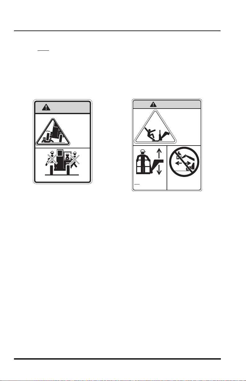
WARNING
Allow no riders
AVOI D
CRUSHING,
falling off
vehicle can
cause death
or serious
injury
FALLING OFF ATTACHMENT,
can result in death or
serious injury.
DO NOT TRAVEL
with personnel in
a work platform.
4110389
Lift or lower personnel
only in a compliant
work platform.
WARNING
OU0620
OH3180
6. Elevating Personnel
Use only a compliant work platform meeting the ASME B5 6.6 standards
for lifting and lowering per sonnel. NEVER transpo rt personnel in a work
platform for even the shortest distance.
Death or serious personal injury can occur if these rules are not
obeyed. Riders can fall and be crushed or run over. Avoid accidents.
For other specific precautions, See “Elevating Personne l” on page 107..
16
Model MMV Rev. 10/11
Safety Practices
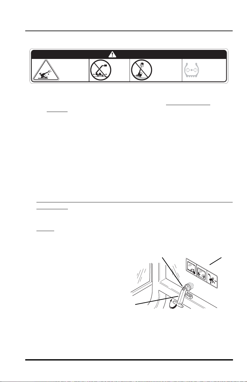
DANGER
DO NOT raise
boom while
on a slope
unless load
is level.
VEHICLE
TIPOVER
can result
in death or
serious injury.
DO NOT
travel
with the
boom
raised.
MAINTAIN
proper tire
pressure at
all times.
OS0086
2.
3.
1.
2
1
3
OU09201
7. Tip Over Hazard
Traveling with the boom raised is dangerous and can cause tipover.
Keep the boom as low as possible. Travel with ex treme caution
the slowest
possible speed.
Keep the vehicle under control at all times. When negotiating turns,
slow down and turn the steering wheel in a smooth sweeping motion.
Avoid jerky turns, starts or stops. Reduce vehicle speed on rough
ground and slopes.
DO NOT exceed the rated lift capacity of the vehicle as structural
damage and unstable conditions will result.
To ensure that the vehicle is positioned in the most stable condition
before operating an attachment, use the frame sway control (frame tilt)
to level the vehicle. The vehicle is level when the frame level indicator
gauge reaches (0°) zero degrees.
If the vehicle cannot be leveled using the frame sway control, repositio n
the vehicle.
Frame swaying left or right with the boom raised above horizontal is
dangerous. Always use the frame sway control to level the vehicle
before
raising the boom above horizontal, with or without a load. If t he
vehicle cannot be leveled using frame sway control, reposition the
vehicle.
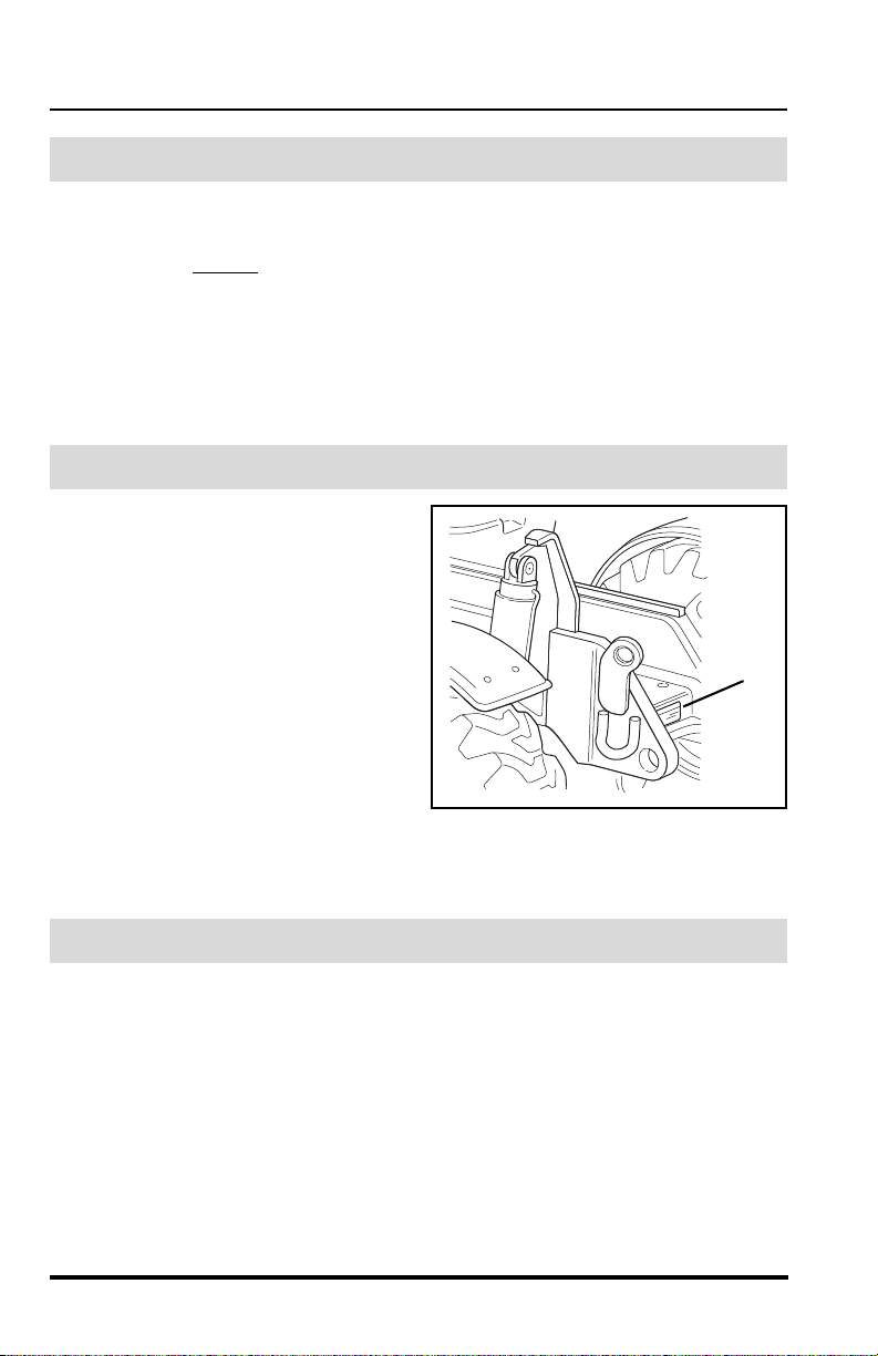
8. Emergency Exit Rear
Window
and at
The rear window (1) in the
enclosed cab can be used
as an emergency exit by
removing the latch pin (2)
located on the window latch
(3). The window is then free
to swing open.
Model MMV Rev. 10/11
17
Safety Practices
DANGER
DO NOT raise
boom while
on a slope
unless load
is level.
VEHICLE
TIPOVER
can result
in death or
serious injury.
DO NOT
travel
with the
boom
raised.
MAINTAIN
proper tire
pressure at
all times.
OS0085
DO NOT JUMP.
Brace yourself.
Stay in cab.
Keep seat belt on.
if vehicle tips.
Jumping can
result in death
or serious
injury.
DANGER
AVOID CRUSHING
OH3190
9. Tire Pressure
MAINTAIN proper tire pressures at all times. An underpressurized
tire(s) adversely affects vehicle stability. If proper tire pressures are not
maintained, this vehicle can tip over.
To ensure proper vehicle stability, check all four tire pressures before
operating the vehicle.
10.Do Not Jump
If a vehicle ever becomes unstable and starts to tip over:
• BRACE YOURSELF and STAY WITH THE VEHICLE,
• KEEP YOUR SEAT BELT FASTENED,
• HOLD ON FIRMLY and
• LEAN AWAY FROM THE POINT OF IMPACT.
Indecision and trying to escape from a tipping vehicle can result in
death or serious personal injury.
18
Model MMV Rev. 10/11

Safety Practices
11. Slopes
DO NOT park the vehicle on an incline and leave it unattended.
• Driving across a slope is dangerous, as unexpected changes in
the slope can cause tipover. Ascend or descend slopes slowly
and with caution
• Ascend or descend slopes with the heavy end of the vehicle
pointing up
NOTE: The rear of the vehicle is normally considered the he avy end unless
the carriage is fully loaded. In this case the front of the vehicle is now the
heavy end.
• Unloaded vehicles should be operated on all slopes with the
carriage pointing down
• On all slopes, the load must be tilted back and raised only as far
as necessary to clear the ground.
• When operating on a downhill slope, reduce travel speed and
downshift to a low gear to permit compression braking by the
engine and aid the application of the service brakes.
.
the slope.
the slope.
12.Falling Load Hazard
DO NOT exceed the total rated load capacity of the specific type fork
being used. Each fork is stamped with a maximum load capacity. If the
capacity is exceeded, forks may break. See “Fork Rating” on page 104.
DO NOT downshift at a high ground speed. Sudden slowing can cause
the load to drop off the forks.
13.Ventilation
Sparks from the electrical system and the engine exhau st can cause an
explosion. DO NOT operate this vehicle in an area with flammable dust
or vapors unless good ventilation has removed the hazard.
Carbon monoxide fumes from the engine exhaust can cause
suffocation in an enclosed area. Good ventilation is very important
when operating this vehicle.
Model MMV Rev. 10/11
19
Safety Practices
4110468
CAUTION
ENGINE OVERHEATING
can occur.
Consult Operator Manual
for coolant filling
procedure.
OM2290
Equipment Considerations
WARNING: DO NOT modify or alter (weld, drill, etc.)
any part of this vehicle without first consulting JLG. Modifications
can weaken the structure creating a hazard that can cause death
or serious personal injury.
DO NOT by-pass or disconnect any electrical or hydraulic circuits.
Consult the JLG Service Department or your local JLG Authorized
Service Center (ASC) if any circuit is malfunctioning.
DO check for frayed or cut seat belt webbing, damaged buckles or
loose mounting brackets. Replace immediately if required.
ALWAYS wear a seat belt when operating the vehicle.
DO check tire pressure on all four tires. Add air if required.
DO check the condition of all four rims. Check for bent flanges and/or
bead mounting areas.
DO check the parking brake/transmission de-clutch operation. Refer to
the test procedures on page 241. Repair immediately if required.
DO keep all non-skid surfaces clean and free of debris. Replace if worn,
damaged or missing.
DO check the condition of decals and/or decal plates. Replace decals
or decal plates if missing, damaged or illegible. The following page s
show the proper location of the decals and/or decal plates.
Engine cooling system MUST be properly filled and all trapped air bled
from the cooling system. Refer to “Drain and Flush Radiator” on
page 149 for filling and bleeding procedures.
20
Model MMV Rev. 10/11
Safety Practices
WARNING
Allow no riders
AVOID
CRUSHING,
falling off
vehicle can
cause death
or serious
injury
DO NOT JUMP.
Brace yourself.
Stay in cab.
Keep seat belt on.
if vehicle tips.
Jumping can
result in death
or serious
injury.
DANGER
AVOID CRUSHING
SAFETY
INSTRUCTIONS
4110361
1. Read operator's
manual before
operating.
2. Fasten
seat
belt.
3. Allow
no
riders.
4. Use a compliant
work platform to lift
or lower personnel.
0000000
RPM X 100
5
10
15
30
20
25
F
1/2
E
104
176
80
248
120
°C
°F
D
r/min
Item Part Number Quantity Decal Description
1
4110358 1 No Riders Warning
2 4110358 1 Vehicle Rollaway Warning
3 4108991 1 Electrocution Danger
4 6623762 1
Load Chart Booklet - 87 psi (600 kPa)
Full Tire Pressure
5 6623944 1
Load Chart Booklet - 60 psi (414 kPa)
Reduced Tire Pressure
6 6623997 1
Load Chart Booklet - 45 psi (310 kPa)
Reduced Tire Pressure
7 4110137 1 Tipover Danger
8 4110358 1 Do Not Jump Danger
9 41 10361 1 Safety Instructions
OM1760
3
9
1
8
7
2
4
5
6
Model MMV Rev. 10/11
21
Safety Practices
A
MOVING PARTS can cut.
Keep clear of fan and belts
while engine is running.
MOVING PARTS can entangle.
B
ENGINE EXPLOSION
can result in death or
serious personal injury.
DO NOT use Ether or
other high energy
starting aids.
Engine equipped with
grid heating system.
3Y949-4110463
3Y949-4110304
WARNING
DO NOT TRAVEL
with personnel in
a work platform.
FALLING OFF ATTACHMENT,
can result in death or
serious injury.
Lift or lower personnel
only in a compliant
work platform.
4110468
CAUTION
ENGINE OVERHEATING
can occur.
Consult Operator Manual
for coolant filling
procedure.
1YHH8-1706549
CAGE CODE
PIN
S/N
NSN
CONTRACT NO.
NOMENCLATURE
TRUCK, LIFT FORK, VARIABLE REACH ROUGH TERRAIN
MODEL: SKYTRAK MMV GVW: 26,900 LBS
CAPACITY: 11000 LB SHIPPING WEIGHT: 30,500 LBS
NSN:
DES. ACT/MFR: 1YHH8 HEIGHT 93.6 IN.
WARRANTY: MO. WIDTH 100.2 IN.
DATE OF MFR.: CUBE 1796.5 CU. FT.
DATE SHIPPED: REG. NO.
DATE INSPECTED & STAMP:
CONTRACT
SERIAL
NO.
1YHH8-1001092290
1001121649_A
SLAVE 24
VOLTS DC
SHIPPING DATA FOR
SKYTRAK MMV
TRUCK, LIFT FORK, VARIABLE REACH
ROUGH TERRAIN, 11,000 POUND CAPACITY
1YHH8-4110306
1YHH8-1706549
CAGE CODE
PIN
S/N
NSN
CONTRACT NO.
NOMENCLATURE
Model
1YHH8-6623990
Serial Number
Year of Manufacture
Max Weight Without Attachments Max Capacity
Sky Trak
OM20502
1YHH8-1706549
CAGE CODE
PIN
S/N
NSN
CONTRACT NO.
NOMENCLATURE
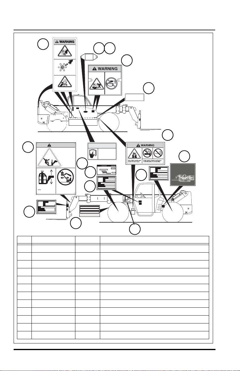
Item Part Number Quantity Decal Description
1
4110184 4 Moving Parts Warning
2 4110303 2 Explosive Gases Warning
3 4110304 1 Carrying Personnel Warning
4 4110305 1 Boom Angle Indicator
5 4110463 2 Ether Start Warning
6 4110468 1 Coolant Filling Caution
7 1001092290 1 Machine Identification Plate
8 1706549 6 Universal ID Plate
9 6623390 1 MMV Serial Number Plate
10 4110306 1 Shipping Data Plate
11 1001121649 1 Slave Decal, 24V DC
12 3576086 1 Engine Identification Plate
2
1
3
5
4
6
7
8
9
8
10
11
1288
22
Model MMV Rev. 10/11
Operation
8
7
9
10
OM1770
Operation
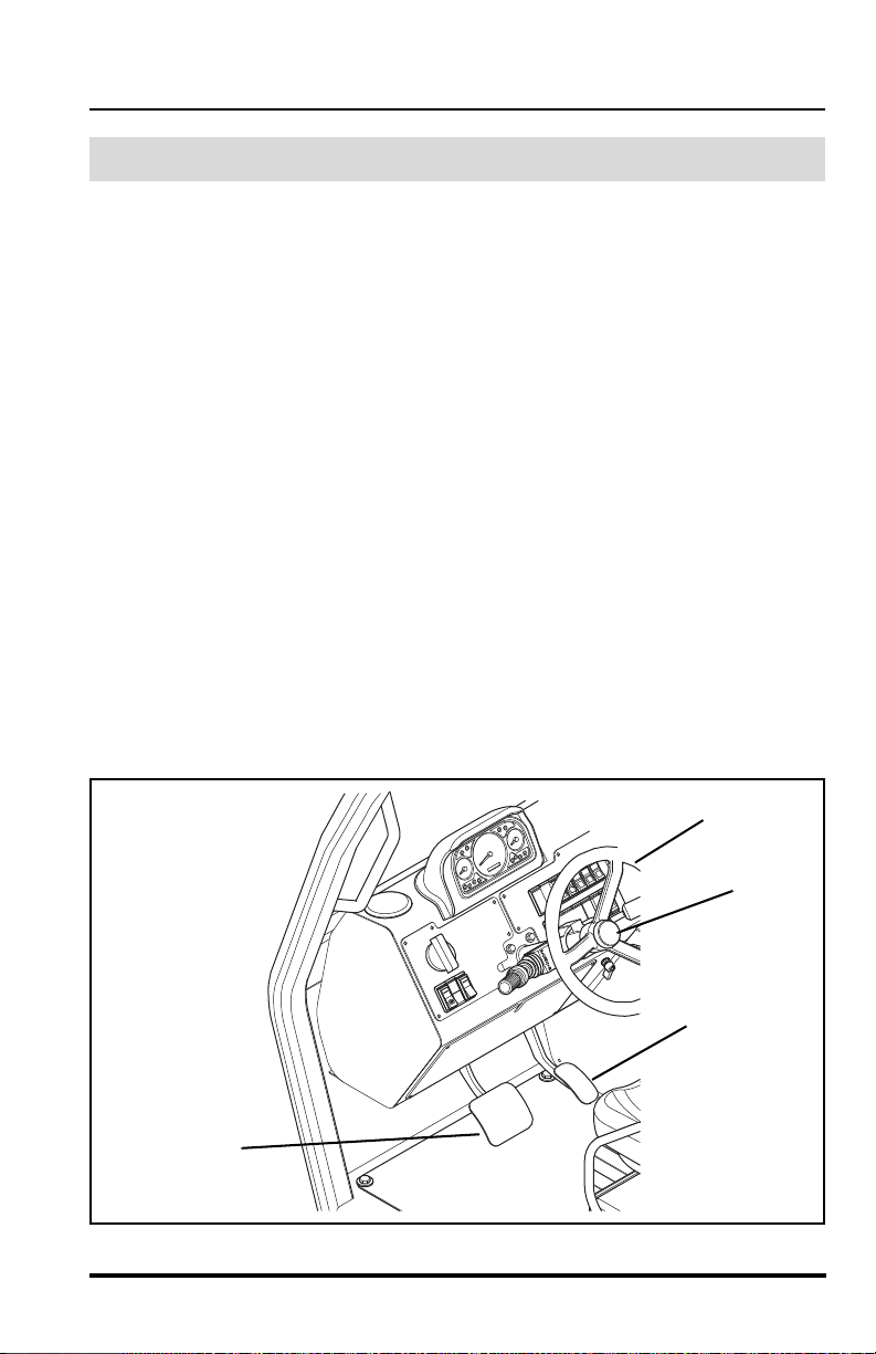
Operator Controls
Accelerator Pedal
Pressing down the accelerator pedal (7) increases engine and hydraulic
speed of the vehicle. The pedal is spring-loaded to return to idle speed.
NOTE: The accelerator pedal is also used to activate the Cummins ECM
diagnostic system. With the ignition in the RUN position, depress and
release the pedal 3 times to activate the system.
Service Brake Pedal
Pressing down the brake pedal (8) decreases the speed of the vehicle by
applying the service brakes located in the axles. In the event of engine
power loss, the service brake pedal can also be used for braking.
Steering Wheel
Turning the steering wheel (9) to the left or right steers the vehicle in the
corresponding direction. Any one of the steering modes are selectable.
Refer to “Steering Mode Selector” on page 25.
Horn Button
Pressing the horn button (10) sounds the horn. When the blackout light
system is activated the horn will not operate.
Model MMV Rev. 10/11
23
Operation
OM1780
2
3
4
1
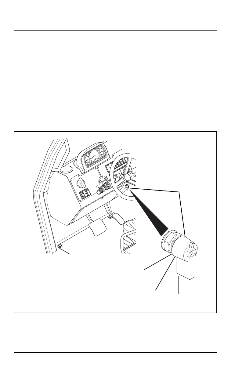
Ignition Switch
The ignition switch (1) is located on the right side of the lower front dash.
The switch may be turned clockwise from the OFF (2) position to the RUN
(3) and START (4) positions. To rotate the switch to the START position,
push the switch IN and rotate to the START position. The START position is
spring-loaded to return to the RUN position and must be manually held in
place for starting.
OFF position (2) — The entire electrical system is shut down.
RUN position (3) — All controls and indicators are operable.
ST ART position (4) — Engages st arter motor to crank the engine when the
parking brake switch is engaged and the transmission is in NEUTRAL.
24
Model MMV Rev. 10/11
Operation
5
OM1790
786
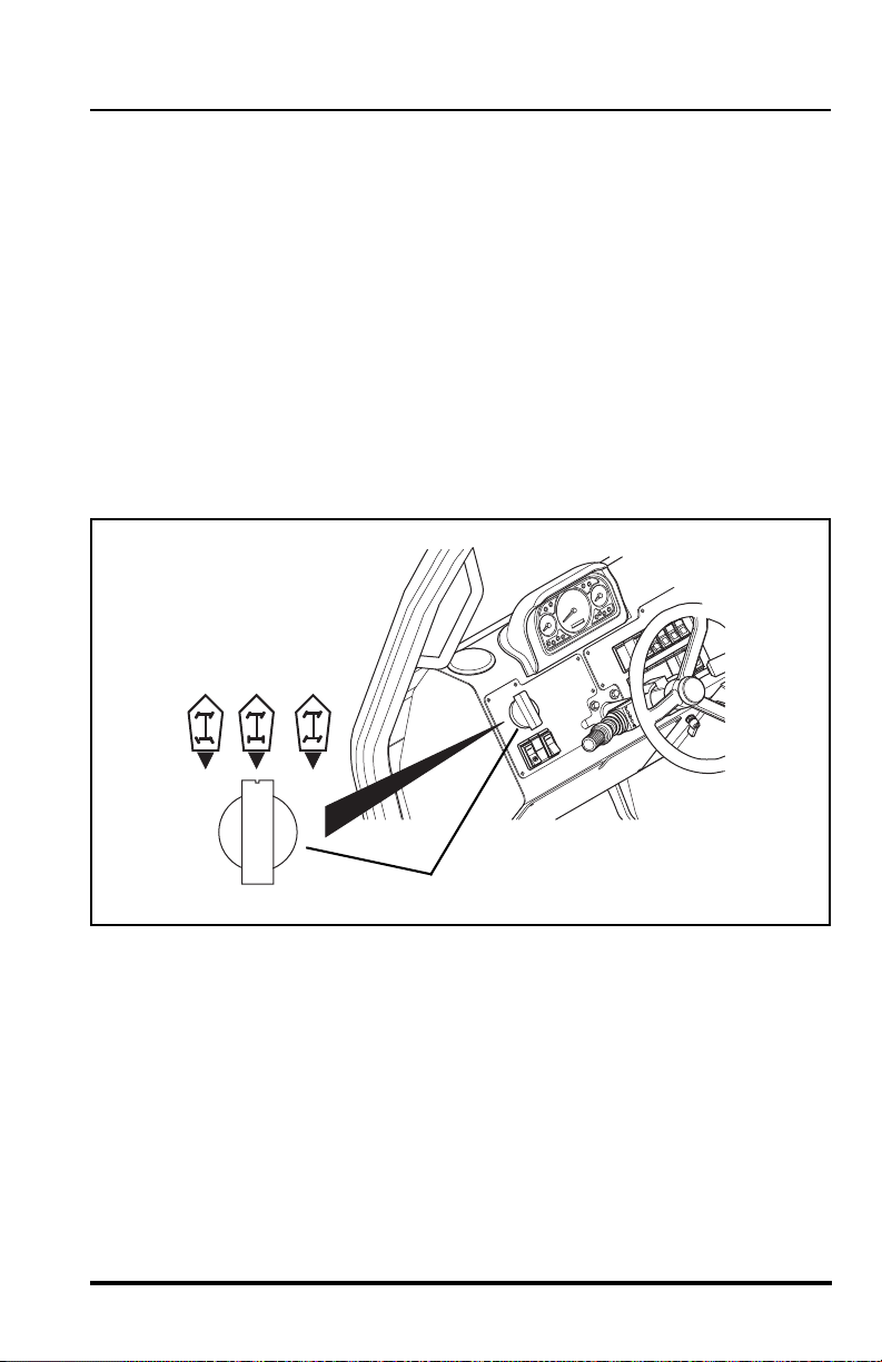
Steering Mode Selector
Three Mode Steer Select
This vehicle has one steering mode selector (5) located on th e left side of
the front dash. The selector has three positions.
• Front Wheel Steer (6).
• Crab Steer (7).
• Four Wheel Steer (8).
Turn the steer mode selector until the notch at the top of the knob points to
the desired steering mode selection. You will feel the knob of the selector
slip into a detent position for each mode.
Refer to “Steering Modes” on page 79 for detailed information.
Model MMV Rev. 10/11
25
Operation
P
P
OS0121
OS1323
5
F
1/2
E
D
OU0381
1
2
3
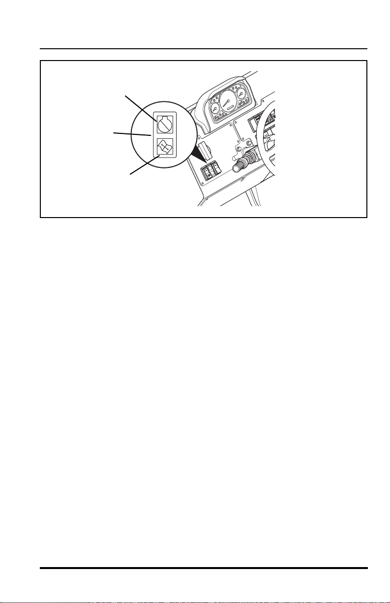
Parking Brake Switch
The Parking Brake Switch (1) has two positions:
ENGAGED............toggle switch downward
DISENGAGED...........toggle switch upward
The Parking Brake Switch must be ENGAGED to permit engine starting. A
red LED, on the parking brake switch, will indicate the brake is ENGAGED.
The parking brake engaged light (2) will illuminate on the front dash panel
any time the parking brake is engaged.
The parking brake may be used to stop in an EMERGENCY situation.
However, use caution because the stop will be abrupt and the operator and
the load may be jolted forward unexpectedly.
With boom angles greater than 40°, this switch activates the locked mode of
the Stabil-TRAK system.
26
Model MMV Rev. 10/11

Operation
OH2591
OH2611
OM3630
OFF
ON
1
Transmission Disconnect Switch
The transmission Disconnect switch (3) is located on the left side of the
front dash and has two positions.
• Push the TOP of the rocker switch in to
DEACTIVATE the transmission disconnect
function.
• Push the BOTTOM of the rocker switch in to
ACTIVATE the transmission disconnect
function.
With the transmission disconnect activated, when the
service brake pedal is applied, the transmission will be disconnected
allowing the engine speed to be increased without the need to place the
transmission shifter in the (N) NEUTRAL.
This feature eliminates the need to shift the trans mis sio n to the (N)
NEUTRAL before operating the hydraulic system at high engine speed.
When the transmission disconnect is active, the drivetrain is disconnected
and the hydraulic system has full engine power.
IMPORTANT! W ith the disconnect feature active and the service brake
pedal being released, the transmission will be reconnected in the same
gear and direction of travel as when it was originally disconnected. The
service brakes must remain fully applied for this feature to be functional.
Battery Disconnect Switch (S/N MV1210 & After)
The battery disconnect switch (1) is located in the engine compartment.
This switch, when turned to the "OFF" position, disconnects the circuit
between the batteries and the electrical syste m . The ba ttery disconnect
switch should be turned to the "OFF" position during periods of ext ended
storage.
Model MMV Rev. 10/11
27
Operation
0000000
RPM X 100
5
10
15
30
20
25
F
1/2
E
104
176
80
248
120
°C
°F
D
r/min
N D
1
2
OM1800
OT0570
OT0580
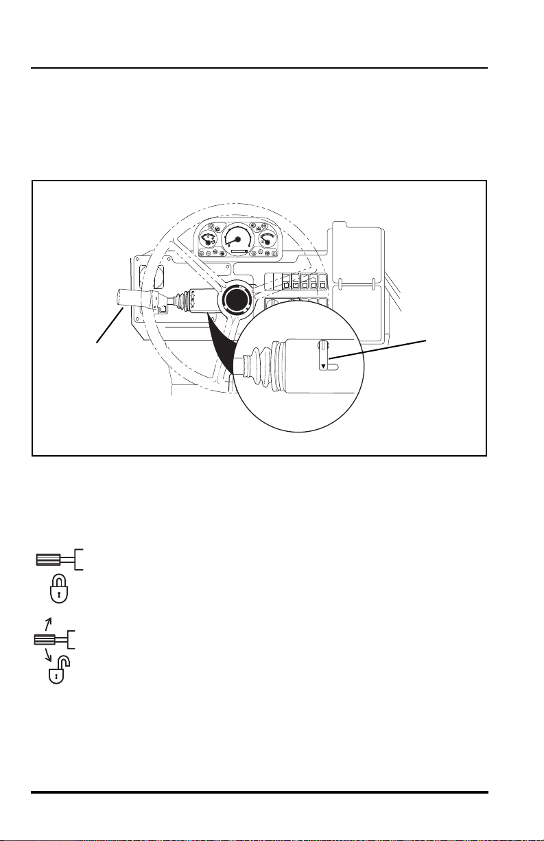
Neutral Lock Lever
The Travel Select Lever (1) is equipped with a neutral lock. The Neutral
Lock Lever (2) locks the Travel Select Lever in NEUTRAL or unlocks the
Travel Select Lever so that it can be moved into the FORW ARD or
REVERSE drive position.
To lock the Travel Select Le ver (1) in the NEUTRAL position, pla ce the lever
in the NEUTRAL position and move the Neutral Lock Lever (2) to the (N)
NEUTRAL LOCK position.
To unlock, move the Neutral Lock Lever to the (D) DRIVE position.
N = NEUTRAL LOCK ..................all the way LEFT
D = DRIVE......... ... .......................all the way RIGHT
Model MMV Rev. 10/11
28
Operation
OS0340
F
N
R
3
OM1810
4
5
6
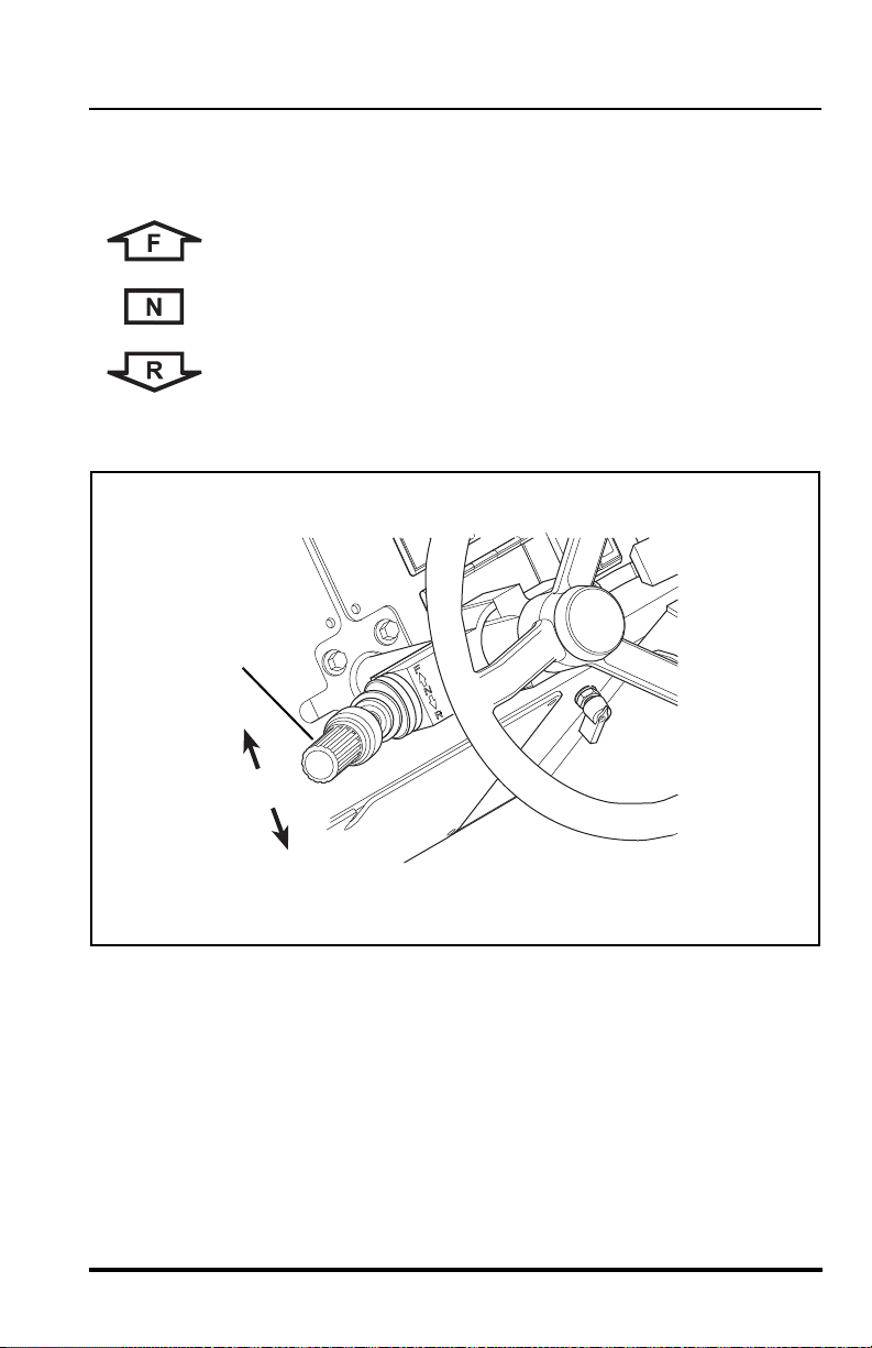
Travel Select Lever
The Travel Select Lever (3) has three positions to select direction of travel:
F = FORWARD (4)......... all the way UP
N = NEUTRAL (5) .......... CENTER position
R = REVERSE (6)...........all the way DOWN
To change travel selections, move the lever UP or DOWN to the desired
selection.
When the Travel Select Lever is shifted to REVERSE, the back-up alarm
will automatically sound. When the blackout light system is activated the
back-up alarm will not operate.
NOTE: The Travel Select Lever must be in the (N) NEUTR A L po sit ion to
permit engine starting.
Model MMV Rev. 10/11
29
Operation
1st
4th
3rd
2nd
1
OM1820
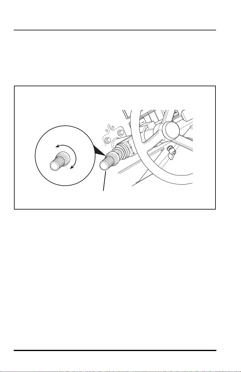
Gear Select Lever
The Gear Select Lever (1) has a twist grip handle with four positions.
Vehicles have four forward gears and three reverse gears.
NOTE: When traveling up a slope, shift to a lower gear as appropriate to
avoid “lugging” the engine.
Use first gear for highest torque and pulling power. Use higher gears for
higher ground speed. The recommendations listed in the “Load Capacity
To Travel Speed Tables” begining on page 94 a re guidelines only. Always
use good judgement when traveling with a load.
30
Model MMV Rev. 10/11
Operation
OS2120
2
OM1830
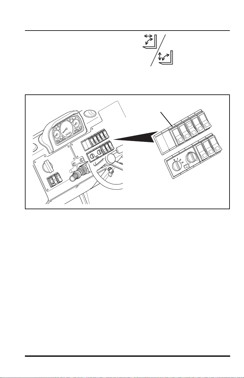
Attachment Tilt Mode Switch
The Attachment Tilt Mode Switch (2) ha s
two positions which allow the operator t o
chose between the Lift/Lower function
and the Extend/Retract function
accompanying the Attachment Tilt capability. For detailed information, see
“Multi-Function Joystick Operation” starting on page 32.
Model MMV Rev. 10/11
31
Operation
OM1880
2
1
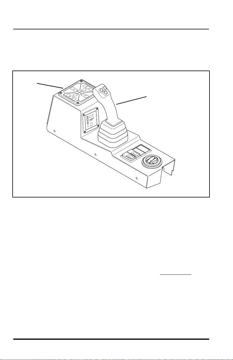
Multi-Function Joystick Operation
The joystick (1) is equipped with four buttons that enable the joysti ck to
operate in three specific modes. The joystick controls boom movement,
attachment tilt and frame sway control.
The logic panel (2) (located in front of the joystick) will illuminate the specific
mode that corresponds with the movement of the joystick (1) and the
selected buttons.
Two functio ns can be accomplished at the same time by mo ving the joystick
in between quadrants. For example; in Mode 1, moving th e joyst ick forward
and to the left will lower and retract the boom simultaneously.
The speed of the function depends directly upon the amount of joystick
travel in the corresponding direction. Increasing the engine speed will also
increase the function speed.
IMPORTANT! Be aware that joystick modes will change immediately
upon
depressing or releasing of any button when the joystick is in an off-center
position.
32
Model MMV Rev. 10/11
Operation
OS0600
3
OM0660
4
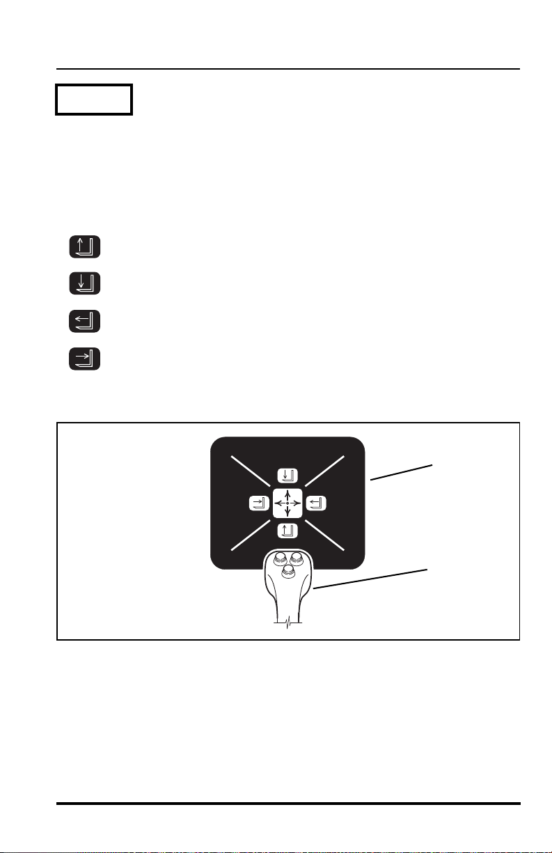
Mode 1
Boom Control (Default)
(No buttons depressed)
This mode is accomplished by using the multi-function joystick (3) without
depressing any of the buttons. All four function lights will illuminate on the
logic panel (4).
Boom Lift............................... move handle backward
Boom Lower.......................... move handle forward
Boom Extend .........................move handle to the right
Boom Retract.........................move handle to the left
Model MMV Rev. 10/11
33
Operation
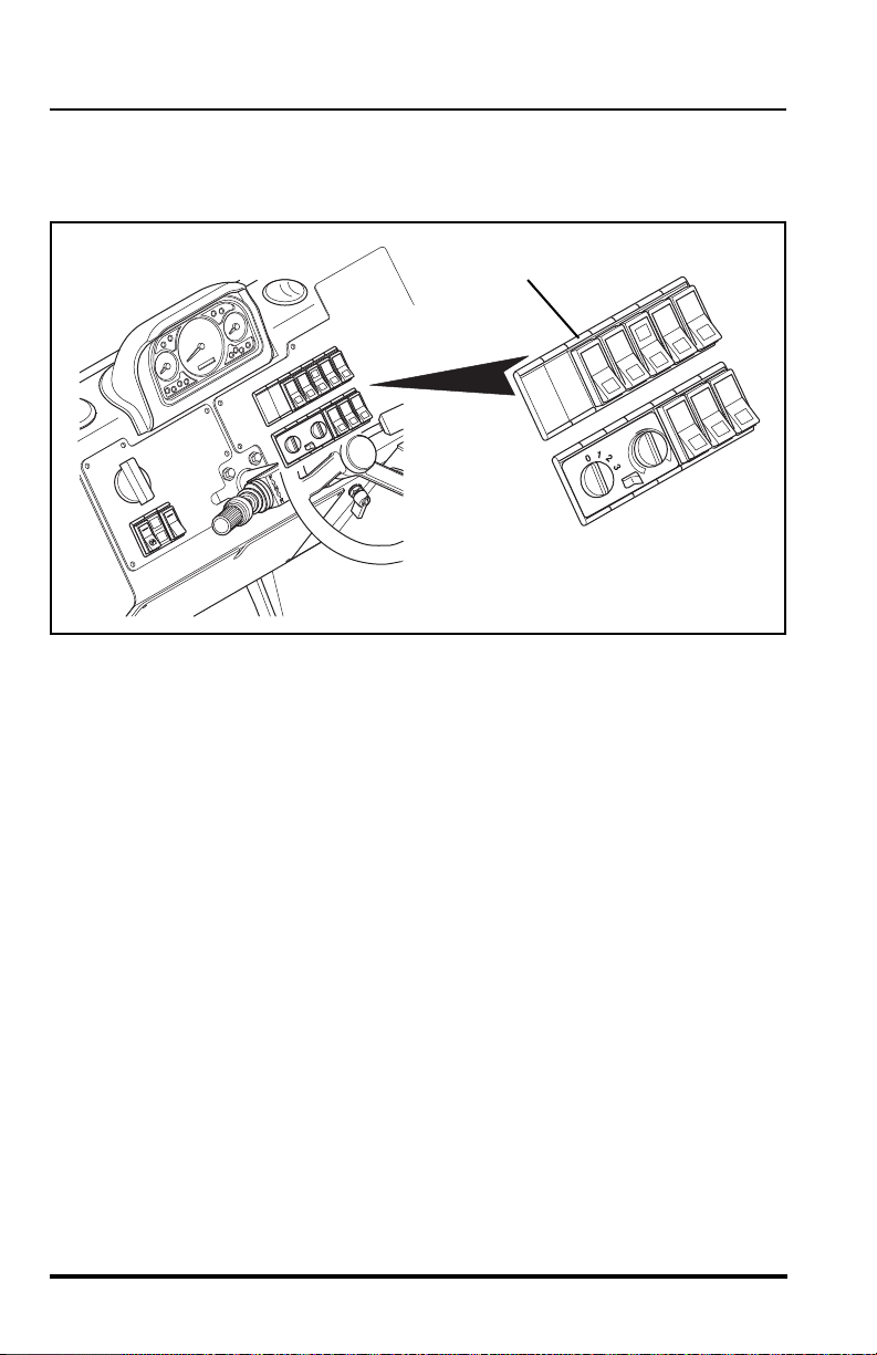
1
OM1830
For the attachment tilt mode covered in Mode 2A and 2B on the following
pages, use the attachment tilt mode switch (1) locate d in the upper bank of
switches to the right of the steering wheel.
34
Model MMV Rev. 10/11

Operation
OM0670
OS0671
2
OM0680
4
3
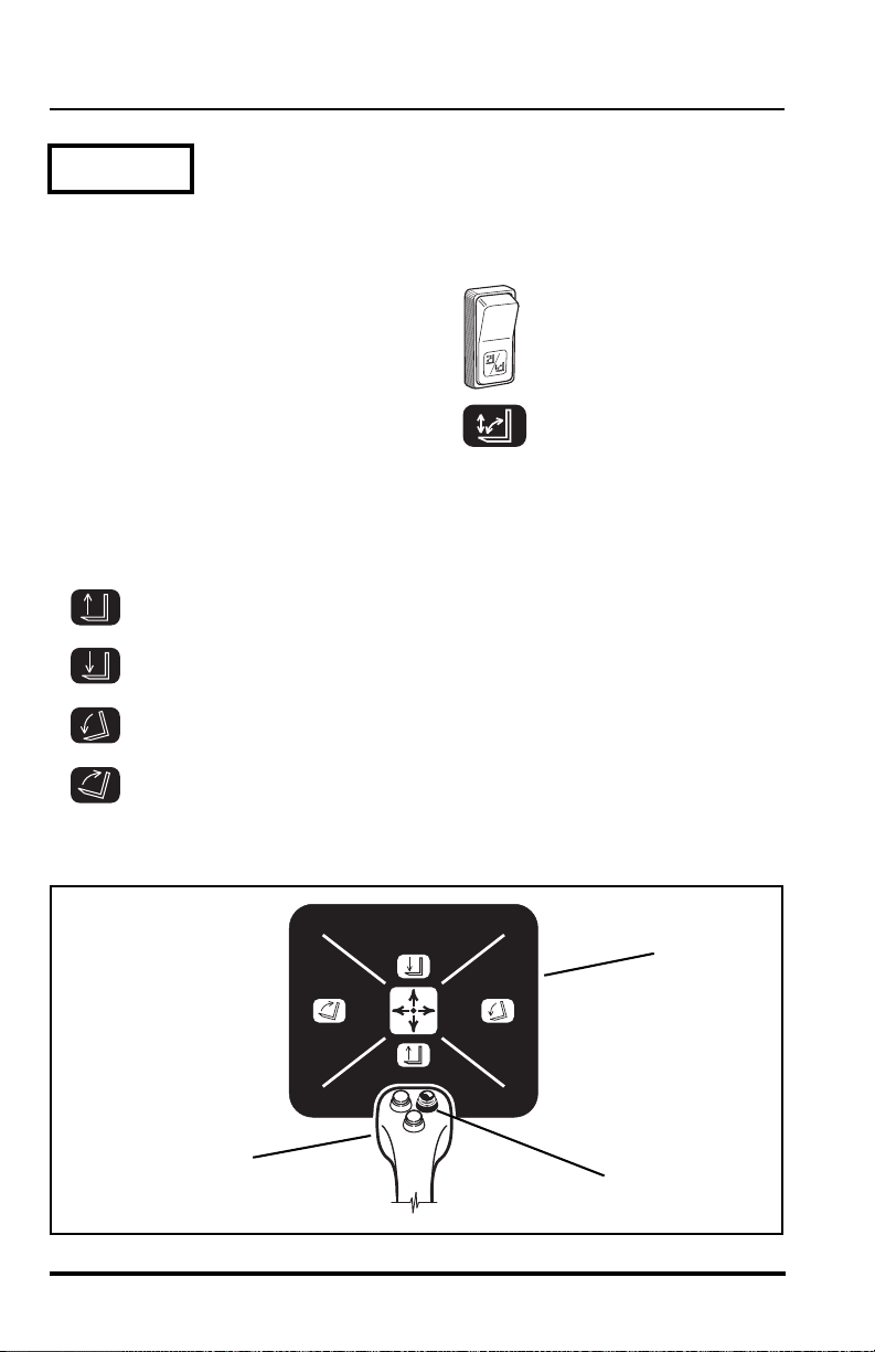
Mode 2A
Attachment Tilt Up/Down & Boom Extend/Retract
(Right button depressed)
Press the top of the attachment tilt mode
switch in.
Press and hold the right button (2) on the top side of the muti-function
joystick (3). As the mode is activated the corresponding lights will illuminate
on the logic panel (4).
Attachment Tilt Up................. move handle backward
Attachment Tilt Down............ move handle forward
Boom Extend .........................move handle to the right
Model MMV Rev. 10/11
Boom Retract.........................move handle to the left
35
Operation
OM0690
OS0610
1
OM0700
3
2
Mode 2B
Boom Lift/Lower & Attachment Tilt Up/Down
(Right button depressed)
Press the bottom of the attachment tilt
mode switch in.
Press and hold the right button (1) on the top side of the muti-function
joystick (2). As the mode is activated the corresponding lights will illuminate
on the logic panel (3).
Boom Lift ...............................move handle backward
Boom Lower ..........................move handle forward
36
Attachment Tilt Down ............move handle to the right
Attachment Tilt Up.................move handle to the left
Model MMV Rev. 10/11

Operation
OS0611
4
OM0710
7
5
6
4
6
Mode 3
Boom Lift/Lower & Frame Sway Right/Left
(Depress left & front buttons simultaneously, then hold eith er button)
This mode is accomplished by using the multi-function joystick (4) and
depressing the front (5) and left (6) buttons simultaneously, then while
holding either button, move the joystick to the required function. As the
mode is activated the corresponding lights will illuminate on the logic panel
(7).
Boom Lift............................... move handle backward
Boom Lower.......................... move handle forward
Frame Sway Right .................move handle to the right
Frame Sway Left....................move handle to the left
Model MMV Rev. 10/11
37

Operation
OM0880
2
OM1880
1
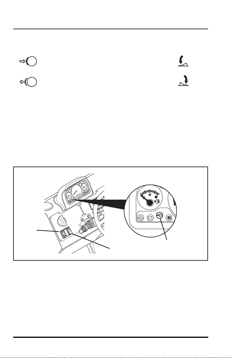
Fork Shift Control Switches
The left (1) and right (2) fork shift switches shift the individual forks on the
carriage to the left or right. The rocker switches are spring loaded to return
to the center (stop) position when released.
Left Fork, Shift to the Left ..............press top of left switch
Left Fork, Shift to the Right............press bottom of left switch
Right Fork, Shift to the Left............press top of right switch
Right Fork, Shift to the Right..........press bottom of right switch
Seat Belt
Always wear the seat belt when operating the vehicle. The seat belt has
one retractable strap (3) for easy installation and removal. Insert the seat
belt tang into the receptacle (4) to fasten. Press the center red button ( 5) to
unfasten the seat belt.
38
Model MMV Rev. 10/11

Operation
OM1840
3
4
5
WARNING: Serious bodily injury or death may result
from failure to wear the seat belt installed on this vehicle. The seat
belt is a critical component of the Operator’s Protective Structure,
and is provided for the operators protection in case of vehicle
upset. The seat belt MUST be worn whenever this vehicle is operated.
IMPORTANT! Inspect the seat belt every time it is used, looking for cut or
worn webbing, or any defect in the latch assembly. If any wear or damage is
noted, DO NOT operate the vehicle until the seat belt is replaced.
Before the engine is started, adjust the seat as required for position and
comfort. Then adjust the seat belt as follows:
1. Grasp both free ends of the belt and make certain that the belt webbing is not twisted or entangled in any portion of the seat assembly.
2. With your back straight in the seat, couple the retractable end of the
belt into the receptacle end of the belt.
3. With the belt as low on your body as possible, pull the retractable
end of the belt to away from the receptacle end of the belt until it is
tight across the lap.
4. To release the belt latch, depress the red button (5) an d pull the
free end (3) from the buckle (4).
Model MMV Rev. 10/11
39

Operation
OM1840
1
2
3
Operators Seat Adjustments
The operator’s seat can be adjusted three ways:
Fore and Aft Adjustment
Pull the handle (1) outward to adjust the seat forwar d an d
backward. Release the handle to lock the seat in the desired
position.
Suspension Adjustment
Turn the knob (2) on the front of the seat to adjust the suspension to
correspond with the operator’s weight. Turn clockwise to increase
stiffness. Turn counter-clockwise to reduce the stiffness.
Backrest Angle Adjustment
The angle of the seat backrest can be adjusted t o suit th e ope rator.
Move the lever (3) located on the left side the seat backrest to
adjust the angle.
40
Model MMV Rev. 10/11

Operation
OM1550
OH2570
OM1830
4
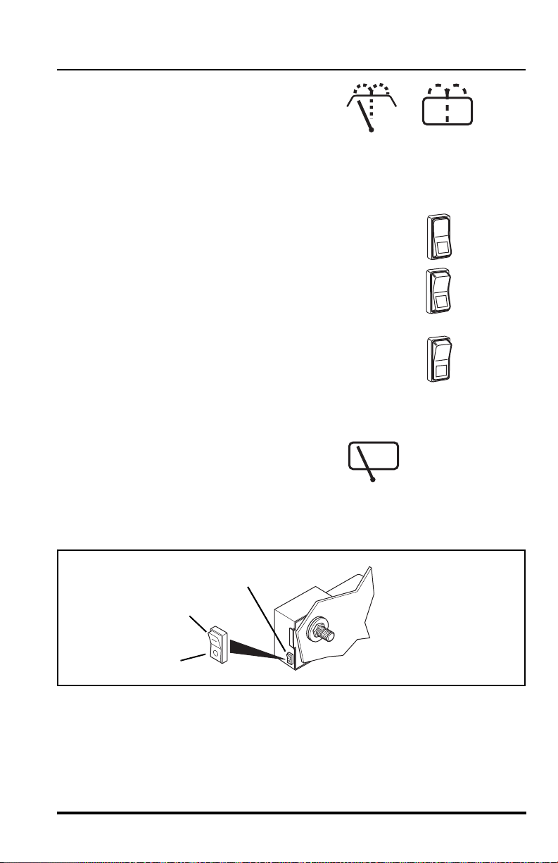
Interior Cab Light
The interior cab light is
located on the top of the
cab just behind the operators head. The interior cab light will operate with
the ignition switch in the OFF or RUN positions.
The interior cab light is operated with a slide type switch located on the light
assembly. To turn the interior light ON, push the switch on the light to the
rear ON position. Return the switch to the center OFF position to turn the
interior light OFF.
When the blackout light system is activated the interior cab light will not
operate.
Worklights
The worklights are
activated with a rocker
switch (4) located in the
upper bank of switches on the right side of the fr ont dash. There are three
positions - OFF, Boom Worklight and Boom & Rear Worklights. The lights
only work when the ignition switch is in the RUN position and the blackout
light system switch is in the OFF position. When the blackout light syste m is
activated these lights will not operate.
Model MMV Rev. 10/11
41

Operation
OS1900
OM1850
1
2
3
4
5
Parking Lights, Headlights & High/Low
Beam Switch
With the ignition switch ON use the turn signal
switch (1) to control the high/low beam headlights,
turn ON the parking lights and the headlights. Turn the twist grip end (2) of
the turn signal switch counter-clockwise to the first position (3) to turn the
parking lights ON. Turn the twist grip to the second position (4) to turn the
headlights and parking lights ON. Turn the twist grip clockwise to the OFF
position (5) to turn all the lights OFF. Pull the turn signal switch toward you
to switch from low beam to high beam. When the hig h bea m is ON the high
beam indicator light on the front dash panel will illuminate. When the
blackout light system is activated these lights will not operate.
42
Model MMV Rev. 10/11

Operation
OM0840
OM0850
OM1830
6
7
Blackout Light System Activation Switch
The blackout light system activation switch (6) is a
rocker switch, located in the upper bank of switches on
the right side of the front dash. This switch has two
positions system ON and system OFF. This switch
must be in the ON position and the ignition switch in the RUN position
before the blackout driving lights or marker lights can become functional.
Blackout Drive/Marker Lights
This switch (7) is located in the upper bank of switches on the right side of
the front dash. The blackout light system activation switch must be in the
ON position. The blackout drive/marker switch has two positions:
Drive/Marker Lights ON ..................Press bottom of switch
Marker Lights Only ON ...................Press top of switch
Model MMV Rev. 10/11
43

Operation
OS1910
OS1920
OM1860
2
4
3
1
Directional Signals
The directional signals
are activated from the
lever (1) on the right side of the steering wheel. To activate the left turn
signal (2); raise the lever. To activate the right turn signal (3); lower the
lever. To dea ctivate either directional signal, the lever must be manually
returned to the center position. The lever will not cancel automatically after
a turn. When the blackout light system is activated the directional signals
will not operate.
Emergency Flashers
To activate the emergency
flashers; push the emergency
flashers switch (4) located on the front dash to the right of the steering
wheel. When the blackout light system is activated the emergency flashers
will not operate.
44
Model MMV Rev. 10/11
Operation
OU1190
7
5
6
8
9
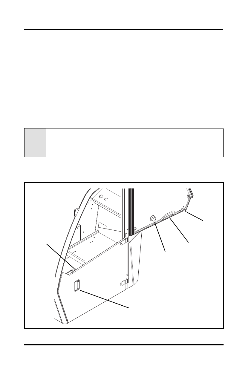
Door Latches
There are two door latches. The outside latch (5) is a pull-to-relea se type.
The inside latch (6) is also a pull-to-release latch.
Door Window Latch
The door window (7) can be swung open by releasing the window from
inside the cab. Release the window from the door with the window latch
handle (8). Pivot the handle out of the way and swing the window open.
Swing the window all the way open and lock in place on the outside of the
cab. The window can be released from inside the cab using the window
release located on the inside of the cab or from the outside, using the
outside release (9) located on the cab door window. The inside and outside
latches are both turn to release locks.
CAUTION: DO NOT operate the vehicle with the door
window swinging free. Damage to the door window could result if
door window is not secured in the OPEN or CLOSED position.
The door window must be latched in the OPEN or the CLOSED position
during operation of the vehicle.
Model MMV Rev. 10/11
45
Operation
2.
3.
1.
OU09201
3
1
2
5
OM2090
4
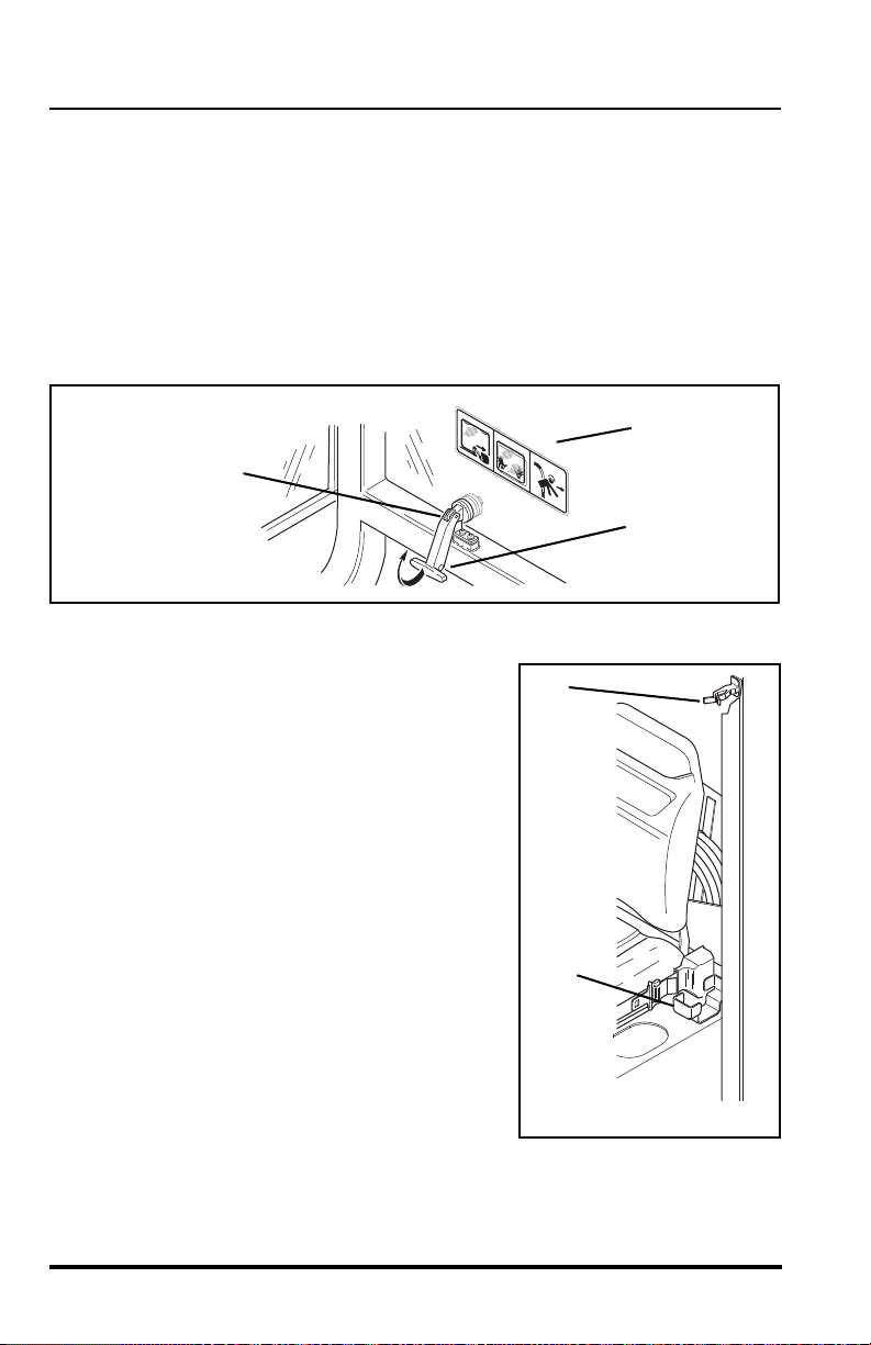
Rear Window Latch
The rear window (1) can be partially opened and secured in place with the
rear window latch. To open the window , grab the latch ha ndle (2) and pull up
and then push the window outward. To close and secure the window, pull
the latch handle up and then inward.
NOTE: In an emergency situation, the operator can exit through the rear
window opening by removing the latch pin (3) on the window la tch. The window is then free to swing open.
Rifle Mount
Stow rifle in stowage mount as follows:
• Position butt of M-16 rifle in the lower
mount (4) with trigger guard forward.
• Position barrel of M-16 rifle in upper
mount (5).
• Check that M-16 rifle is held tightly.
Remove rifle from stowage mount as follows:
• Pull the handle of the upper mount (5)
to the side.
• Remove the barrel of M-16 rifle from
the upper mount.
• Remove the butt of M-16 rifle from the
lower mount (4).
46
Model MMV Rev. 10/11
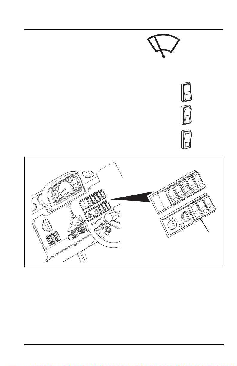
Front Windshield Wiper
OS19301
OH2591
OH2601
OH2611
OM1830
6
The three position front wiper switch (6) is
located in the lower bank of switches to the
right of the steering wheel. this single rocker
switch controls the speed of the front
windshield wiper.
• Push the TOP of the rocker switch in to turn the
front wiper OFF.
• Place the rocker switch in the MIDDLE position to
operate the wiper at LOW speed.
• Push the BOTTOM of the rocker switch in to
operate the wiper at HIGH speed.
Operation
Model MMV Rev. 10/11
47
Operation
OS19401
OH2591
OH2611
OM1830
1
2
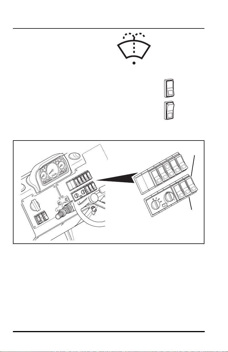
Windshield Washer Control
This rocker switch (1) is spring loaded
to return to the OFF position when
released. This switch is located in the
lower bank of switches to the right side
of the steering wheel.
• Release the switch to deactivate the washer
control.
• Press and hold the BOTTOM of the r ocker switch
in to activate the windshield washer. The rocker
switch is spring loaded and will return to the OFF
position when released.
48
Model MMV Rev. 10/11
Operation
OS2100
OM1520
OH2591
OH2601
OH2611
OM1530
OU0170
3
4
5
Skylight Wiper/Washer & Rear
Window Washer
The skylight (roof) wiper/washer switch and
rear window washer (2) is located in the
lower bank of switches to the right of the steering wheel. It controls the
skylight wiper, skylight washer along with the rear window washer. When
the skylight washer is activated, the rear window washer is also activated.
• Push the TOP of the rocker switch in to turn the
skylight (roof) wiper OFF.
• Place the rocker switch in the MIDDLE position to
turn the skylight (roof) wiper ON. This wiper is a
single speed wiper.
• Push and hold the BOTTOM of the rocker switch
to activate the skylight (roof) and rear window
washers. The rocker switch is spring loaded and
will return to the skylight (roof) wiper, ON position,
when the washer position is released.
Rear Window Wiper
The rear window wiper rocker switch (3) is
located on the motor housing of the rear
wiper.
The switch has two positions; wiper ON (4) and wiper OFF (5).
Model MMV Rev. 10/11
49
Operation
OS1950
OS1960
OM1830
4
1
2
3
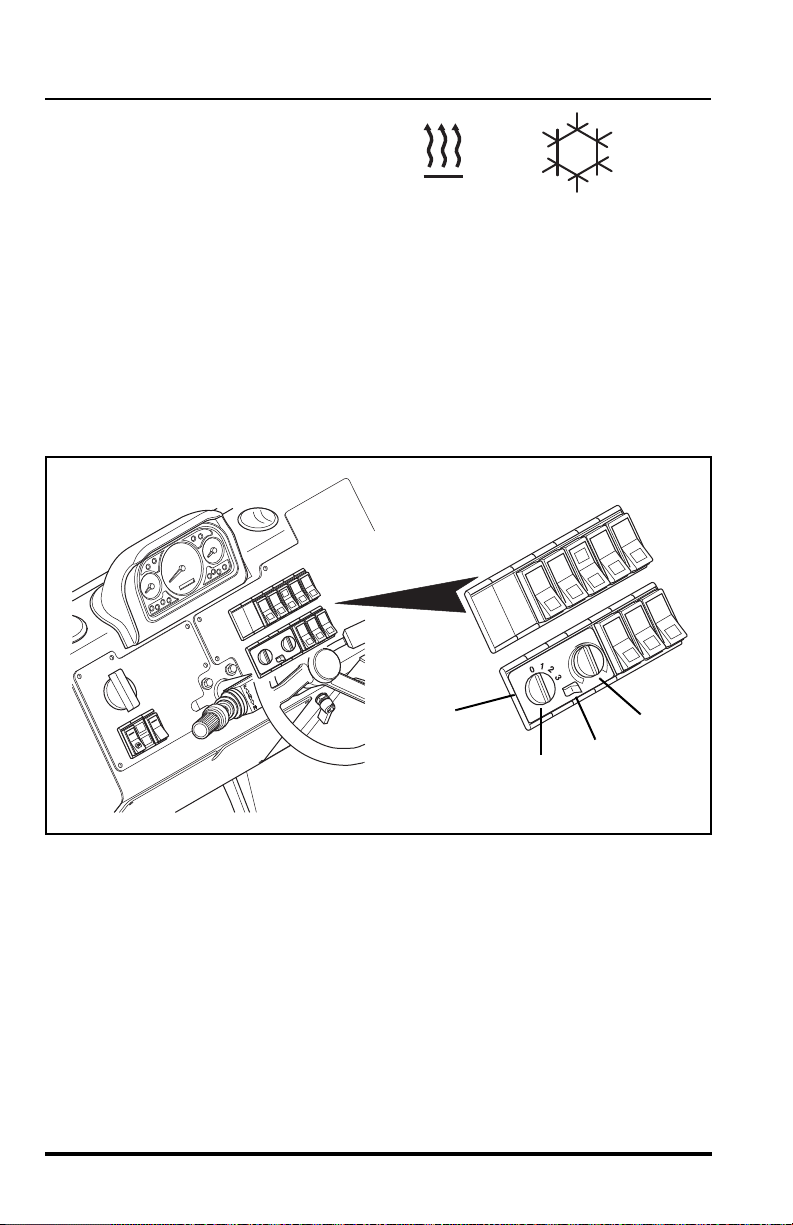
Cab Heater/Air Conditioning
Controls
The cab heater and air conditioning
controls (1) are located next to the
lower bank of switches on the right side of the front dash. From left to right
the control panel consists of: a variable speed fan con tr ol kn ob (2), an A/C
on-off rocker switch (3) and a temperature control knob (4).
Control of air flow is made by opening, closing or redirecting the air vent
louvers in four seperate locations inside the cab. For instance, if the front
glass needs rapid defrosting, red irect the air flow at the front two vents
(directing the vent louvers toward the glass) and close the remaining two
vents. This will increase the volume of air flow to the front glass and speed
defrosting.
50
Model MMV Rev. 10/11
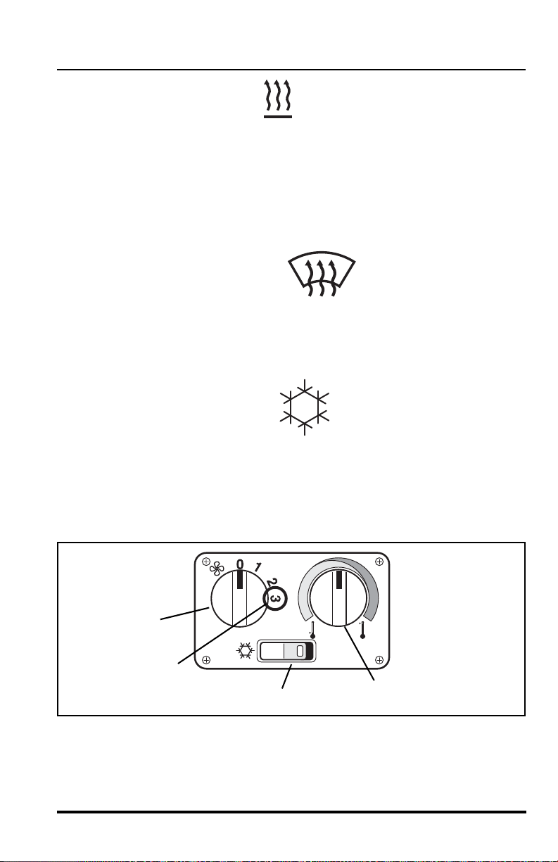
To heat the cab:
OS1950
OA1390
OS1960
OU0930
4
5
2
3
• turn A/C rocker
switch (3) to the
OFF position,
• turn temperature control knob (4) to far right position
(RED = HOT),
• direct desired air flow by adjusting vent louvers,
• turn fan control (2) to “3” (5) to assure rapid warm-up.
To defrost the cab:
• turn temperature control
knob (4) to the far right
position (RED = HOT),
• direct desired air flow by adjusting vent louvers,
• turn fan control (2) to “3” (5) to assure rapid defrost.
To cool the cab:
• turn A/C rocker switch
(3) to the ON position,
• turn temperature
control knob (4) to the far left position (BLUE = COOL),
• direct desired air flow by adjusting vent louvers,
Operation
• turn fan control (2) to “3” (5) to assure rap id cool-down.
Model MMV Rev. 10/11
51
Operation
OM2100
1
2
OH3290
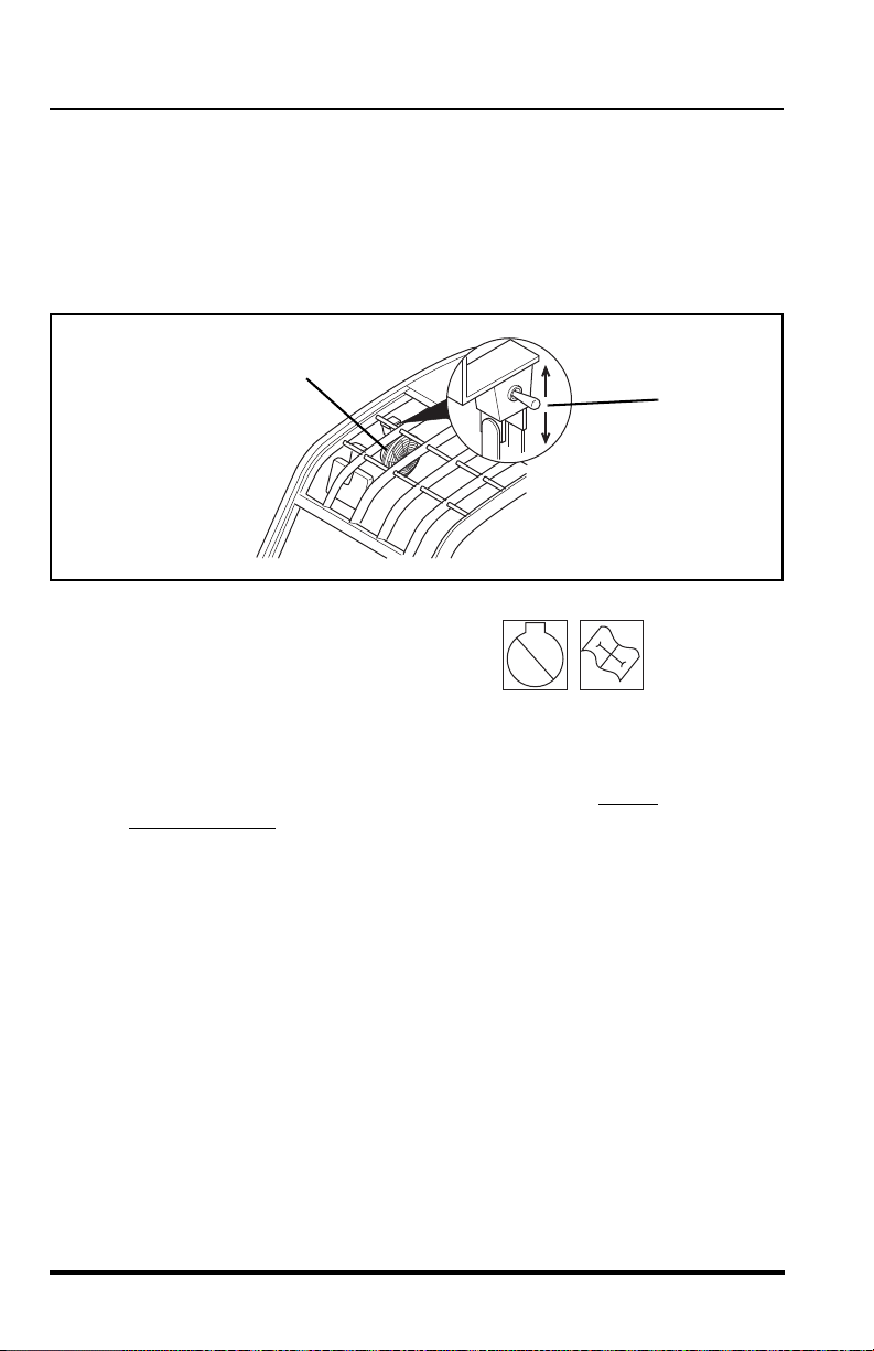
Cab Circulation Fan
The cab circulation fan (1) is located at the top right side of the cab just
above the operators seat. The fan has a three position toggle switch (2)
located on the fan mount. The fan can be operated at HIGH speed (switch
down) or LOW speed (switch up). The fan can be swive led to direct the flow
in the desired direction.
Engine Function Indicator Lights
The engine function indicator lights
(3) are located in the switch bank on
the left side of the front dash. The
light indicates any faults that arise in the engine during operatio n.
The light contains a RED light (4) and a AMBER light (5).
If the RED light (4) comes ON during operation, STOP
IMMEDIATELY
and diagnose the fault by activating the ECM
diagnostic system. Activate the system with the accelerator pedal.
the engine
52
Activate the system and read the code as indicated by the RED
light (4). Contact your local Cummins dealer for an explanation of
these codes or refer to the Cummins Engine Owners Manual or call
the Cummins Customer Assistance Center at 1-800-34 3-7357.
If the AMBER light (5) comes ON during operation, the engine
diagnostic system has detected a fault within the engine. Stop the
engine and diagnose the fault by activating the ECM diagnostic
system.
Model MMV Rev. 10/11
Activate the system and read the code as indicated by the light.
OM1870
3
4
5
Contact your local Cummins dealer for an explanation of these
codes or refer to the Cummins Engine Owners Manual or call the
Cummins Customer Assistance Center at 1-800-343-7357.
Cummins ECM Diagnostic System Activation
With the engine OFF, turn the ignition switch to the RUN position.
DO NOT start the engine.
Completely depress and release the accelerator pedal three times.
This will activate the system, both the AMBER light and RED light
will come ON momentarily and then both will begin to flash the
code. If the system has been activated with the accelerator pedal
and no faults are present, both the AMBER light and the RED light
will come ON and stay ON.
Operation
ECM Light Code Identification
The AMBER light will flash one time to identify the start of the code
followed by a one or two second pause. Then the RED light will
flash the code sequence, pausing for one or two seconds between
numbers. The AMBER light will flash once after the RED light has
flashed the code to signify the end of that fault code.
Model MMV Rev. 10/11
53

Operation
0000000
RPM X 100
5
10
15
30
20
25
F
1/2
E
104
176
80
248
120
°C
°F
D
r/min
OU0010
1
2
3
4
5
Front Dash Panel
The front dash panel (1) provides the operator wit h important information. It
is “user friendly” and only provides the oper ator with the inf ormation needed
at any given time.
Front Dash Panel Light Test
To test the front dash panel lights; turn the ignition switch to the RUN
position, ALL the lights (13 total) will come ON for three seconds as a test
function. During this time an audible alarm will sound. Replace any bulbs
that DO NOT come ON during this test.
Do not forget to refasten your seat belt before operation. Always wear the
seat belt when operating the vehicle.
54
Model MMV Rev. 10/11
Operation
OH2260
OS1970
OU0050
OU0040
Function Indicator Lights
There are four “hidden” function indicator lights in the front dash panel that
illuminate only when a specific function has been activated. They are:
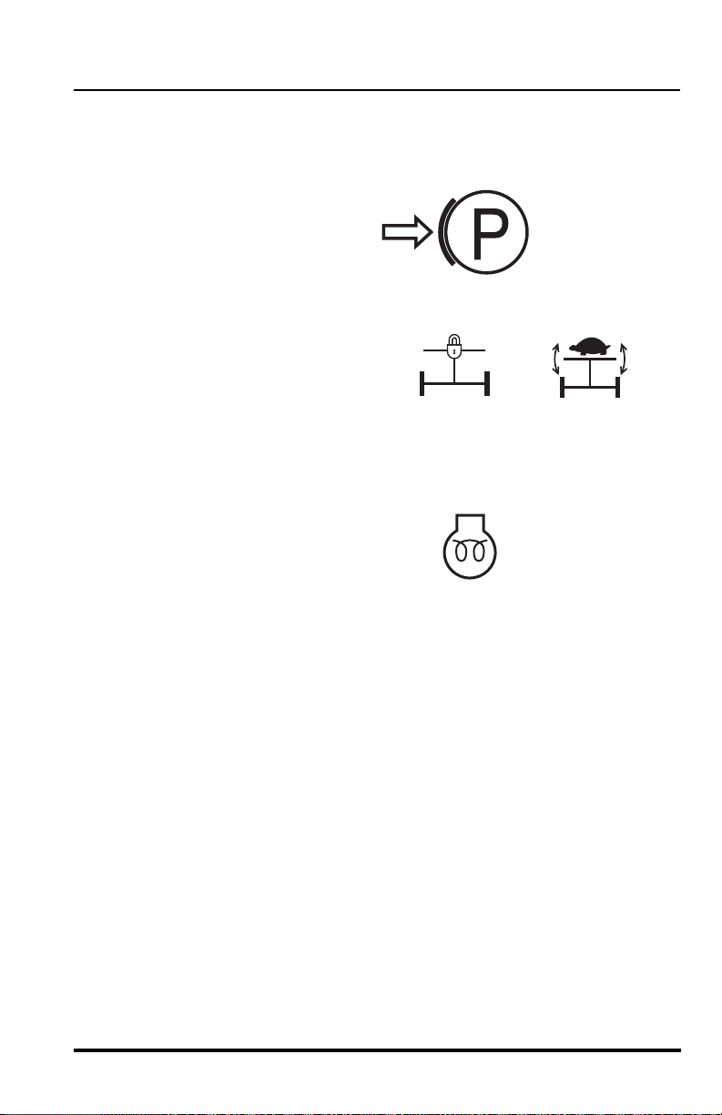
Parking Brake Indicator (2)
This light illuminates any
time the parking brake is
applied and the ignition
switch is in the RUN
position.
Stabil-TRAK Mode Indicator
Lights (3 & 4)
One of these lights will illuminate
when the Stabil-TRAK system
has been ACTIVATED in the
“Locked” Mode (3) or the “Slow Pivot” Mode (4). Refer to
“Understanding the Stabil-TRAK™ System” on page 73 for a
detailed explanation.
Engine Air-Intake Heater Indicator (5)
This light illuminates, with the
ignition switch in the RUN position,
any time the ambient temperature
drops below 40° F (4° C). The engine grid heater then becomes
active and the engine should not be cranked until the light goes
OFF. Once the light goes OFF it indicates that the grid heater is at
the proper temperature and the eng ine is read y to star t.
NOTE: This indicator light may come ON when the engine is running to indicate that the post heat function is active. This is a normal condition when
ambient temperatures are below 40° F (4° C).
Model MMV Rev. 10/11
55

Operation
OT0990
OT1000
OT1010
Warning Indicator Lights
There are seven additional “hidden” indicator lights in the front dash panel
that will illuminate during critical circumstances. all seven warning indicator
lights demand immediate attention and vehicle servicing. In many cases,
the vehicle should be shut down AS SOON AS PRACTICAL
serious mechanical failure.
The warning indicator lights are:
Transmission Temperature Warning
Indicator (1)
This light illuminates when the
transmission oil temperature is too
high; above 250° F (121° C). An audible alarm will also sound. Stop
and idle the vehicle with the transmission in (N) Neutral, allowing
time for cooling. If the light does not go out after two minutes, shut
the vehicle down.
Hydraulic Oil Temperature Warning
Indicator (2)
This light illuminates when the
hydraulic oil temperature is too high;
above 195° F (91° C). Stop and idle the
engine, allow time for cooling. If the light does not go out after five
minutes, shut the vehicle down.
Engine Oil Pressure W arning Indicator (3)
to prevent
56
This indicator light will come ON if the
engine is not started. This is normal. If
the light comes ON while the engine is
running, this indicates that the engine oil pressure is t oo lo w. When
the engine is running an audible alarm will also sound when the low
oil pressure light is ON.
SHUT THE VEHICLE DOWN AS SOON AS PRACTICAL.
Model MMV Rev. 10/11

Alternator Charging Warning Indicator (4)
OH2560
OT1020
OT1030
0000000
RPM X 100
5
10
15
30
20
25
F
1/2
E
104
176
80
248
120
°C
°F
D
r/min
OU0010
1
2
3
4
6
5
This light illuminates to indicate a weak or
improperly working charging system or the
batteries are dead. Service the engine
alternator or batteries.
Engine Air Filter Restriction Warning
Indicator (5)
This light illuminates when a restricted
engine air filter is detected. If the light is ON,
service the air filter(s).
Hydraulic Oil Filter Restriction
Warning Indicator (6)
This light illuminates when a restricted
hydraulic oil filter is detected. If the light is
ON, service the hydraulic oil filter.
Operation
Model MMV Rev. 10/11
57

Operation
OM1600
0000000
RPM X 100
5
10
15
30
20
25
F
1/2
E
104
176
80
248
120
°C
°F
D
r/min
OU0010
1
2
3
4
5
Low Brake Pressure Warning Indicator (1)
This light is located on the lower right
side of the front dash panel.
The light will come ON and the buzzer
sounds when service brake hydraulic system pressure drops below
the safe operating level. Under normal conditions, the light and
buzzer will go out quickly after engine start. If the light or buzzer
does not go out or comes ON during vehicle operation, shut off
engine immediately, investigate, and repair before operating. DO
NOT operate vehicle when low brake pressure light or buzzer is on.
WARNING: Operating the vehicle with the service
brake system malfunctioning will cause reduced braking ability or
no braking ability when the service brake pedal is depressed.
Death or serious personal injury could result from the inability to
stop or slow the vehicle.
If the low brake pressure light or buzzer remains ON, place the
travel select lever in (N) NEUTRAL, place the neutral lock lever in
the (N) NEUTRAL LOCK position, engage the parking brake switch
and turn the engine OFF.
Have the service brake system serviced before using the vehicle
again. Contact your local JLG Authorized Service Center (ASC)
immediately to repair the system.
Model MMV Rev. 10/11
58

Gauges and Indicators
OH24701
r/min
OU0020
OU0030
OT0980
Fuel Level Gauge (2)
Make sure the vehicle is level to
ensure an accurate fuel level
reading. The fuel gauge located
on the left side of the front dash panel, indicates the amount of fuel
in the fuel tank. Refuel before the fuel gauge reaches the “E” to
prevent running out of fuel. Capacit y o f th e fu el tan k is 50 . 2 gallo ns
(190 liters) total capacity with a usable capacity of 45 gallons
(171 liters). If the engine ever runs out of fuel, the fuel system will
need to be bled. Refer to “Bleeding Fuel System” page 160.
Engine Tachometer (3)
The tachometer is the gauge in
the center of the front dash panel
and indicates speed of the
engine in revolutions per minute
(rpm).
Hourmeter (4)
The hourmeter records engine
operating hours and has a total
readout of 99,999.99 hours. It is
located on the front dash panel in the lower portion of the
tachometer.
Operation
Engine Coolant Temperature
Gauge (5)
The engine coolant temperature
gauge is located on the right side
of the front dash panel. Glance at
the gauge on a regular basis during operation. The gauge monit ors
the temperature at which the engine is operating. If the gaug e goes
over 210° F (99° C) the engine coolant is too hot. Idle the en gine for
1 minute prior to shutting the vehicle down. If the radiator is boiling
over, SHUT THE VEHICLE DOWN AS SOON AS PRACTICAL.
Model MMV Rev. 10/11
59
Operation
OS1900
OH2510
0000000
RPM X 100
5
10
15
30
20
25
F
1/2
E
104
176
80
248
120
°C
°F
D
r/min
OU0010
1
2
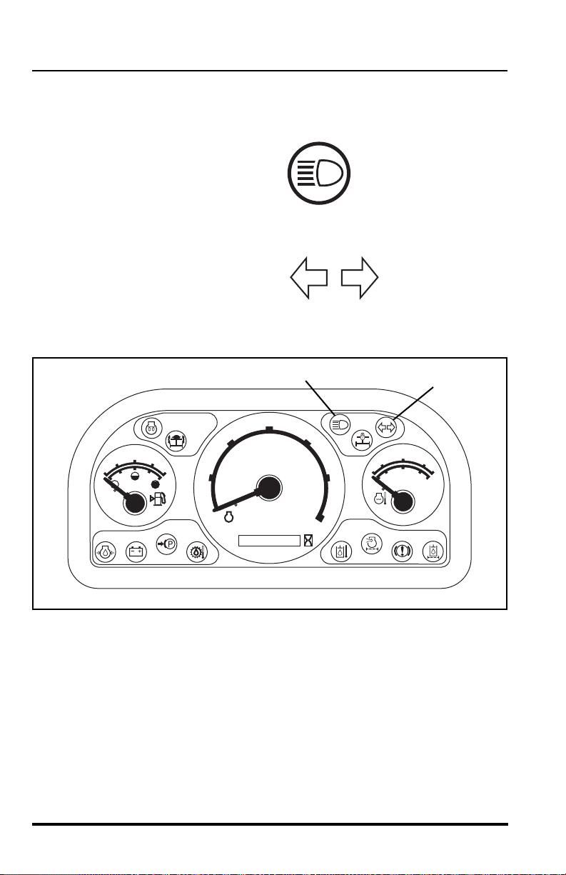
Additional Indicator Lights
There are two additional “hidden” indicato r lights in the front dash panel that
will illuminate only when the road lights are activated.
High Beam Indicator (1)
Whenever the headlights are
on “high” beam this light will
illuminate and remain ON until
the headlights are switched to
“low” beam.
Turn Signal Indicator (2)
The turn signal indicator light
will illuminate and flash when
the turn signals are activated
in either direction or when the hazard lights have been activated.
60
Model MMV Rev. 10/11
Operation
OS0232
3
OM0961
4
5
6
Instruments and Indicators
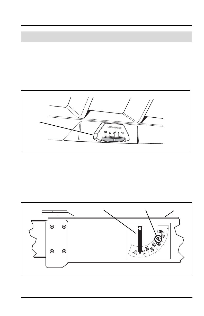
Frame Level Indicator
The frame level indicator (3) is mounted on the top inside of the cab. It is a
bubble type indicator which allows the operator to tell if the vehicle has
been positioned in a level condition. Always frame sway the vehicle either
right or left until the indicator reads zero degrees (0°). If zero cannot be
achieved, then reposition the vehicle until it is level before placing the load.
Boom Angle Indicator
The boom angle indicator is a plumb arrow (4) with angular graduations (5)
from -10° to + 80°. It is located on the left side of the boom (6) and is visible
from the operators position. Use this indicator to dete rmin e the b oom ang le
when reading the capacity chart (see “Using the Capacity Chart” on
page 92).
Model MMV Rev. 10/11
61
Operation
OS1470
2
1
OM1670
3
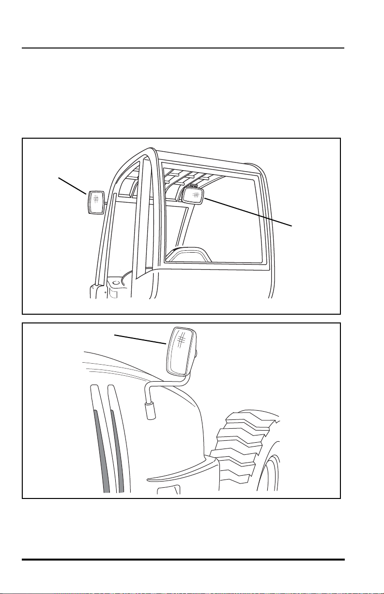
Rear View Mirrors
Three rear view mirrors are provided to aid the operator’s rear visibility. The
mirrors are adjustable and need to be adjusted to obtain the best rear view
possible for the operator. There is one mirror (1) on the left front side of the
cab and a second mirror (2) inside the cab in the upper right front corner.
The third mirror (3) is located on the side of the engine ho od.
62
Model MMV Rev. 10/11

Operation
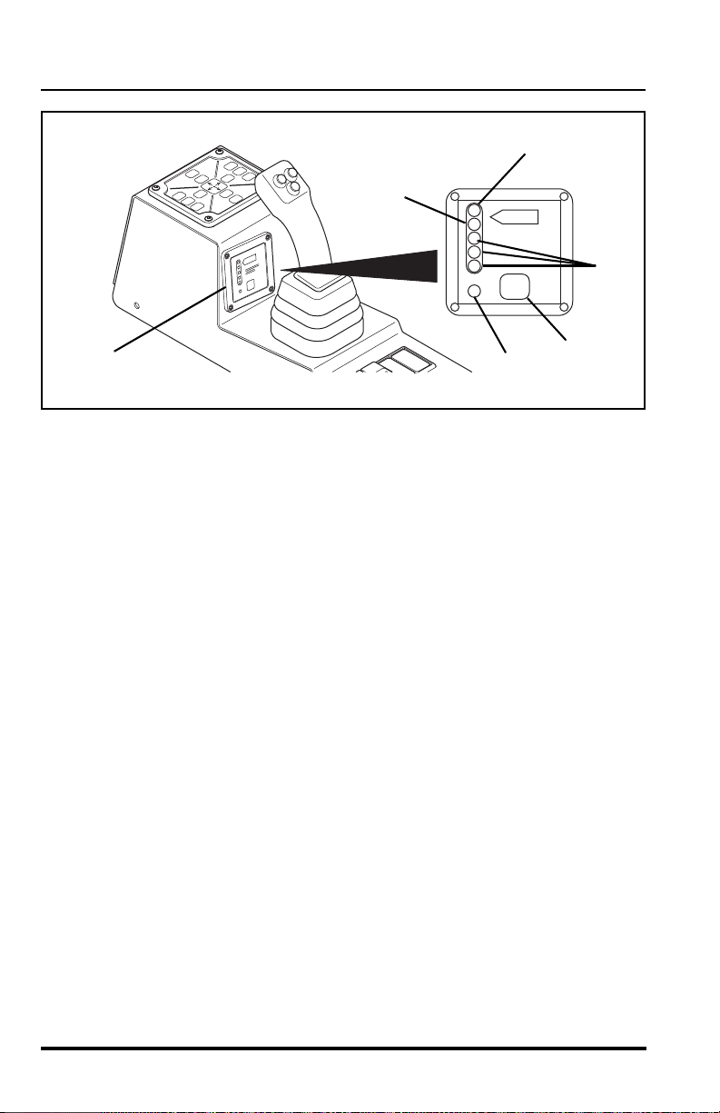
Load Moment Indicator
WARNING: The Load Moment Indicator (L M I) system
is not intended to be an absolute
charts. DO NOT exceed rated capacities! Any attempt to lift or
carry loads in excess of those shown on the capacity chart may
cause vehicle tipover, loss of load or structural damage which
could result in death or serious personal injury.
The load moment indicator is a feature which continually monitors the load
on the rear axle as loads are being lifted and extended. The system alerts
the operator when the ground pressur e on the rea r of the ve hic l e ha s
decreased to a point that the rear of the vehicle could raise up off the
ground. This system indicates the level of forward stability and not
necessarily of sideways stability. The display panel (4) is mounted in front of
the joystick on the right side console.
1. The display has a green power light (5) next to the te st button (6) to
inform the operator that the system is active. This light will come
ON when the ignition is turned to the RUN position.
2. The display has a series of three green lights (7), one amber light
(8), one red light (9) and an audib l e a lar m tha t inf orms t he op er ator
of each operating load range.
3. As the load is extended and reaches 100% of the vehicles capacity,
the three green lights will be lit and the amber light will flash.
replacement for the capacity
4. As the load goes over 100% of the vehicles capacity the red light
will come ON and an audible alarm will sound, alerting the operator
that the load should be retracted.
Model MMV Rev. 10/11
63
Operation
100%
TEST
OM1890
4
6
5
7
8
9
64
Model MMV Rev. 10/11
Operation
100%
TEST
OM1890
2
1
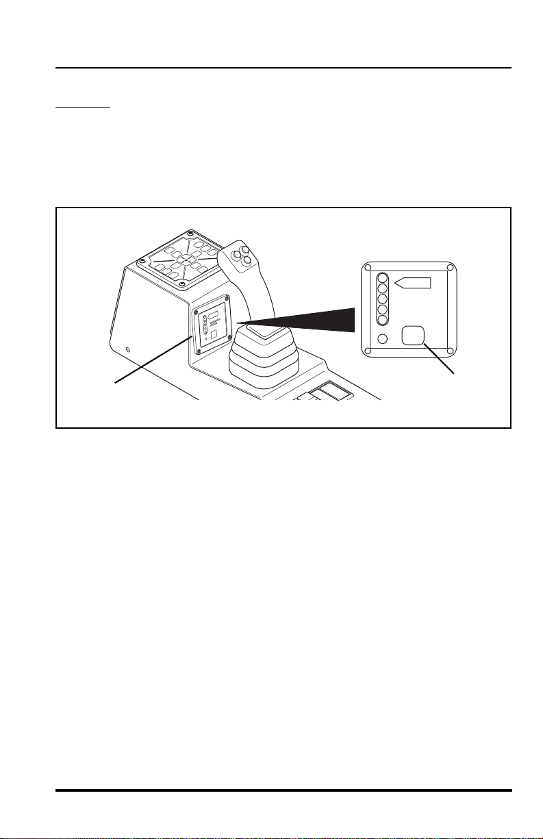
Load Moment Indicator System Test
ALWAYS
Changing Display Settings
The display has muting and dimming settings which allow the operator to
set the level of brightness and the sound level of the alarm. There are four
possible combinations.
To change the settings, PRESS and HOLD the test button (1) continuously
while the display sequences through each combination. Release the test
button when the preferred combination occurs. The combinations are:
test the LMI system before starting to work with a load.
1. Turn the ignition to the RUN position.
2. Momentarily press the test button (1) on the load moment indicator
display (2). ALL the lights should flash ON and the audible alarm
will sound. This will tell you that the display is functioning properly.
• Full Brightness with Full Volume
• Full Brightness with Muted Volume
• Dim Brightness with Full Volume
• Dim Brightness with Muted Volume
Model MMV Rev. 10/11
65

Operation
Pre-Operation Inspection
1. Check safety belt for damage. Check for frayed or cut seat belt
webbing, damaged buckles or loose mounting brackets. Make any
necessary repairs before operating the vehicle.
2. Check all four tires and rims for damage. Check for proper tire pressure, add air if required. Observe the condition of each tire looking
specifically for punctures, cracks, cuts, gouges, bulges or any ot her
damage. Check the condition of each rim for bent flanges or any
other damage. Make any necessary repairs before operating the
vehicle.
3. Check and add engine oil if required. This procedure is explained in
greater detail on page 152.
4. Check and add transmission oil if required. This procedure is
explained in greater detail on page 169.
5. Check the cooling system overflow bottle for coolant. Add coolant if
required. This procedure is explained in greater d etail on page 148.
Remove any debris blocking the radiator cooling fins.
6. Check the hydraulic oil level sight glass and add hydraulic oil if
required. This procedure is explained in greater detail on page 164.
7. Visually inspect the batteries for cleanliness. Check terminals for
corrosion. Check the cable connections to ensure prop er tightne ss.
8. (S/N MV1210 & After) Make sure the battery shut-off switch in the
engine compartment is in the "ON" position.
9. Walk around the vehicle and check for oil leakage as well as damaged or missing parts. Make any necessary repairs before operating the vehicle.
10. Perform the LMI system test. Refer to “Load Moment Indicator System Test” on page 65.
11. Check ALL lighting systems for proper operation.
12. Adjust rear view mirrors as required to obtain proper field of vision
to the rear.
13. Test the back-up alarm and horn for proper operation.
14. Check condition of cab glass, looking for cracks or other damage .
15. Visually check the condition of the air conditioner condenser.
Remove any debris from the cooling fins of the air co nditioner condenser located at the rear of the frame. Clean the fins as needed.
66
Model MMV Rev. 10/11

Operation
Normal Starting
1. (S/N MV1210 & After) Make sure the battery shut-off switch in the
engine compartment is in the "ON" position.
2. Enter the cab and adjust the seat for comfortable operation.
3. Adjust the mirrors to obtain the best rear view from the operator’s
position.
W ARNING: DO NOT start the engine unless you are in
the seat with the seat belt fastened around you. Death or serious
personal injury could result if the belt is not securely fastened.
4. Fasten the seat belt.
5. Make sure the parking brake switch is ENGAGED.
6. Place the travel select lever in (N) NEUTRAL.
7. Move the Neutral Lock Lever to the (N) NEUTRAL LOCK Position.
8. Push and turn the ignition switch to the START position (fully clockwise) to crank the engine. Release the ignition switch when the
engine starts. If the engine fails to start on t he first try, wait until th e
engine and starter come to a complete stop before cranking the
engine again.
IMPORT ANT! DO NOT crank t he start ing mo tor continu ously for mo re than
30 seconds. Stop cranking the starter and allow the starter to cool for 2
minutes before engaging the starter again.
9. After the engine starts, run engine at partia l throttle f or 30 to 60 seconds before operating the vehicle. Return to idle before engaging
the travel or range select levers.
10. Move the Neutral Lock Lever to the (D) DRIVE Position before you
start operating.
11. Disengage the parking brake switch before you start operating.
Model MMV Rev. 10/11
67
Operation
Cold Starting
The engine is equipped with a 120 volt 750 wat t block heater. Block heaters
are recommended when temperatures drop below 10° F (-12° C).
(Temperature ranges will vary when using different oil weights. Consult the
engine manufacturer’s manual for other variables.)
WARNING: This diesel engine uses a grid heating sys-
tem inside the induction manifold. DO NOT use ether or any high
energy fuels to assist starting. An explosion may cause death or
serious personal injury or engine damage.
The engine is equipped with a grid heater inside the induction ma nifold. If
the temperature drops below 40° F (4° C) the air-intake heater system will
be activated when the ignition switch is turned to the RUN position. When
the system is active the air-intake heater light (see page 55) will illuminate
on the front dash panel. DO N OT turn the ignition switch to START until the
air-intake heater light goes OFF.
At temperatures below -10° F (-12° C), operate the engine at moderate
speeds for 5 minutes before full loads are applied.
1. Enter the cab using the hand holds and adjust the seat for comfortable operation.
2. Adjust the mirrors to obtain the best rear view from the operator’s
position.
W ARNING: DO NOT start the engine unless you are in
the seat with the seat belt fastened around you. Death or serious
personal injury could result if the belt is not securely fastened.
3. Fasten the seat belt.
68
Model MMV Rev. 10/11

Operation
4. Make sure the parking brake switch is ENGAGED.
5. Place the travel select lever in (N) NEUTRAL and move the neutral
lock lever to NEUTRAL LOCK position.
6. Turn the ignition switch to the START position to crank the starter.
IMPORT ANT! DO NOT crank t he start ing mo tor continu ously for mo re than
30 seconds. Stop cranking the starter and allow the starter to cool for 2
minutes before engaging the starter again.
7. As the engine starts, release the ignition switch to the RUN position. Depress the accelerator pedal enough to provide a smooth
idle speed.
8. The engine oil pressure warning indicator light should go OFF
within five seconds after starting. If the light remains ON, turn the
ignition switch OFF immediately and check the oil level or change
to a lighter weight oil. Consult the engine manufacturer’ s manual for
alternative oils for cold weather operation.
Model MMV Rev. 10/11
69

Operation
OM3640
1
Slave Starting
WARNING: To avoid death or serious personal injury,
never slave start the vehicle with a frozen battery as it will
explode. Keep sparks, flames and lighted smoking materials away
from the battery. Lead acid batteries generate explosive gases
when charging. Wear safety glasses when working nea r batt eries.
This vehicle is equipped with a 24 volt, negative ground electrical system.
The NATO slave receptacle (1) is located under the eng ine co ve r in fr ont of
the transmission. Ensure that both the disabled and booster vehicle are
equipped with a NATO slave receptacle.
1. Connect the NATO slave cable to the booster vehicle NATO slave
receptacle.
2. Connect the other end of the NATO slave cable to the disabled
vehicle NATO slave receptacle.
3. Run the booster vehicle at a speed just above idle.
4. Follow the steps in “Normal Starting” on page 67.
5. After starting the disabled vehicle, return the booster vehicle to idle.
6. Remove the NATO slave cable from the disabled vehicle first and
then from the booster vehicle.
70
Model MMV Rev. 10/11

Operation
OS0860
Refueling
Make sure the vehicle is level to assure an accura te fuel level reading. The
fuel tank is capable of holding 45 gallons (171 liters) of diesel fuel.
Fuel Types
The preferred fuel is ASTM #2 diesel fuel with a minimum Cetane rating of
40. #2 diesel fuel gives the best fuel economy and performance under most
operating conditions. Fuels with Cetane ratings higher than 40 may be
needed in higher altitudes or extremely low ambient temperatures to
prevent misfiring and excessive smoke.
• When operating at temperatures above 32° F (0° C), use
standard #2 diesel fuel.
• When operating at temperatures below 32° F (0° C), use a blend
of #1 & #2 diesel fuels, most commonly known as “winterized” # 2
diesel.
W ARNING: Engine fuel is flammable and can ca use a
fire or an explosion. Keep sparks and open flames away from th e
vehicle and DO NOT use smoking materials while refueling.
Alternate Fuel Types
The vehicle is also capable of operation on alternate military fuels including
JP-5, JP-8 and Jet A-1. However, an up to 5% reduction in engine
horsepower output can be expected when using alternate military fuels due
to the lower BTU rating of these fuels.
Model MMV Rev. 10/11
71

Operation
OM1900
1
Fuel Cap
The fuel cap (1) is conveniently located on the left side of the vehicle.
The fuel cap meets EPA standards.
To remove the fuel cap:
1. Level the vehicle, ground the attachment, place the travel select
lever in (N) NEUTRAL, move the neutral lock lever to the (N) NEUTRAL LOCK position, engage the parking brake switch and turn the
ignition switch to the OFF position.
WARNING: REMOVE FUEL CAP SLOWLY. Fuel
spray may cause personal injury. Fuel can spray out on you if
you open the cap too quickly or if you fill the tank too rapidly.
2. Slowly turn the cap in a counter-clockwise rotation. Wait for any
“hissing” noise to stop. THEN unscrew the cap all the way and
remove the cap from the filler neck.
To install the fuel cap:
Turn the cap clockwise until the cap bottoms on the filler neck. The fuel
cap is now properly installed.
72
Model MMV Rev. 10/11

Operation
OS1970
0000000
RPM X 100
5
10
15
30
20
25
F
1/2
E
104
176
80
248
120
°C
°F
D
r/min
OM1910
1
2
3
Operating
Understanding the Stabil-TRAK™ System
The following describes the three basic modes of the
patented Stabil-TRAK system. The vehicle may
operate in any one of these three modes.
Free Pivot Mode
With the boom below 40° (1), the Stabil-TRAK system is in the FREE
PIVOT MODE (2) and the rear axle is allowed to pivot freely. The frame
sway control will function normally. Both Stabil-TRAK lights on the front
dash panel will be OFF (3).
Model MMV Rev. 10/11
73

Operation
0000000
RPM X 100
5
10
15
30
20
25
F
1/2
E
104
176
80
248
120
°C
°F
D
r/min
OM1920
4
5
6
7
Locked Mode
With the boom above 40° (4) and by activating one o r more of the fu nctions
(as follows), the Stabil-TRAK system is in the LOCKED MODE (5). The rear
axle is locked so it is rigid with the frame. The Stabil-TRAK lock light on the
front dash panel will be ON (6). The Stabil-TRAK slow pivot light on the front
dash panel will be OFF (7).
• Engaging the parking brake switch
• Placing the travel select lever in (N) NEUTRAL
• Depressing and holding the service brak e pe d al
The frame sway control will function slower than normal in this mode.
74
Model MMV Rev. 10/11

Operation
0000000
RPM X 100
5
10
15
30
20
25
F
1/2
E
104
176
80
248
120
°C
°F
D
r/min
OM1930
1
2
3
4
Slow Pivot Mode
With the boom above 40° (1), the Stabil-TRAK Syst em is now in the SLOW
PIVOT MODE (2). In this mode the rear axle is UNLOCKED and is allowed
to pivot but will respond SLOWLY
slow pivot light on the front dash panel will be ON (3). The Stabil-TRAK lock
light on the front dash panel will be OFF (4).
The frame sway control will function normally in this mode.
To check that the Stabil-TRAK System is functioning properly, refer to the
test procedure on page 237 for the proper system function.
to changes in terrain. The Stabil-TRAK
Model MMV Rev. 10/11
75
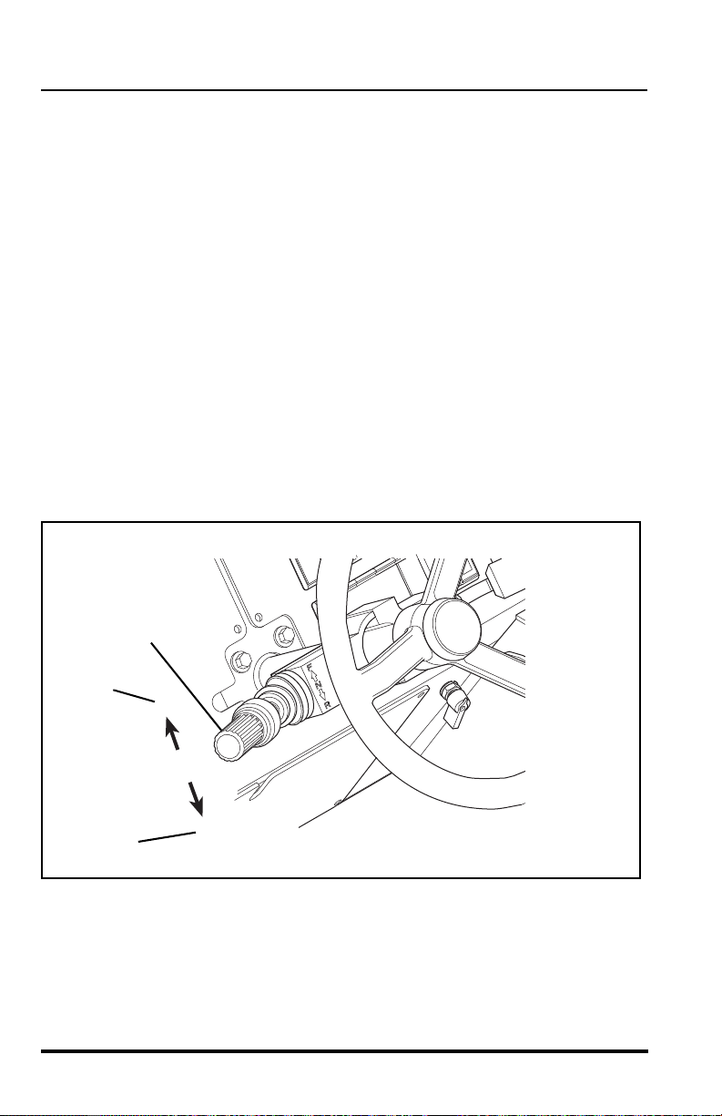
Operation
F
N
R
5
OM1810
6
7
Starting Travel
1. Enter the operator cab, fasten the seat belt, start the engine, apply
the service brake pedal and disengage the parking brake switch.
2. Rotate the twist grip of the range select lever to 1st gear.
3. Move the travel select lever (5) to (F) FORWARD (6) to travel in a
forward direction or to (R) REVERSE (7) to travel backward.
4. Slowly remove your foot from the service brake ped al and press the
accelerator pedal to start travel.
IMPORTANT! Check for warning lights frequently during operation. Any
abnormal indication should be corrected as soon as practical.
Changing Travel Direction
1. Stop the vehicle by applying the service brakes.
2. Grasp the travel select lever (5), pull it toward the steering wheel,
then move the lever up or down in the opposite direction;
(R) REVERSE (7) or (F) FORWARD (6).
76
Model MMV Rev. 10/11

Operation
Shifting Gears
1. Rotate the twist grip of the gear select lever to the next desired
gear. The transmission has four forward gears and three reverse
gears.
2. Use first gear for highest torque and pulling power. Use higher
gears for higher ground speed. The recommendations list ed in the
“Load Capacity To Travel Speed Tables” begining on page 94 are
guidelines only. Always use good judgement when traveling with a
load.
NOTE: Shifting to the next higher gear may be done while the vehicle is in
motion.
IMPORTANT! When downshifting, allow the engine speed to slow down
before shifting to the next lower gear.
Model MMV Rev. 10/11
77

Operation
0000000
RPM X 100
5
10
15
30
20
25
F
1/2
E
104
176
80
248
120
°C
°F
D
r/min
N D
1
OM1800
2
Stopping Travel
1. Apply the service brake pedal and downshift the vehicle to a lower
gear if necessary to slow the vehicle until it comes to a complete
stop.
2. Move the travel select lever (1) to (N) NEUTRAL, move the neutral
lock lever (2) to the (N) NEUTRAL LOCK position and engage the
parking brake switch.
78
Model MMV Rev. 10/11
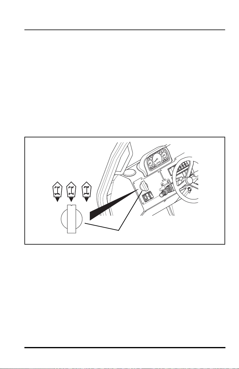
Operation
1
OM1790
342
Steering Modes
IMPORTANT! DO NOT change steering modes unless you are at a
complete stop and all four tires are in the “straight-ahead” position.
This vehicle has one steering mode selector (1) located on th e left side of
the front dash. The selector has three positions.
• Front Wheel Steer (2).
• Crab Steer (3).
• Four Wheel Steer (4).
Turn the steer mode selector until the notch at the top of the knob points to
the desired steering mode selection. You will feel the knob of the selector
slip into a detent position for each mode.
Model MMV Rev. 10/11
79
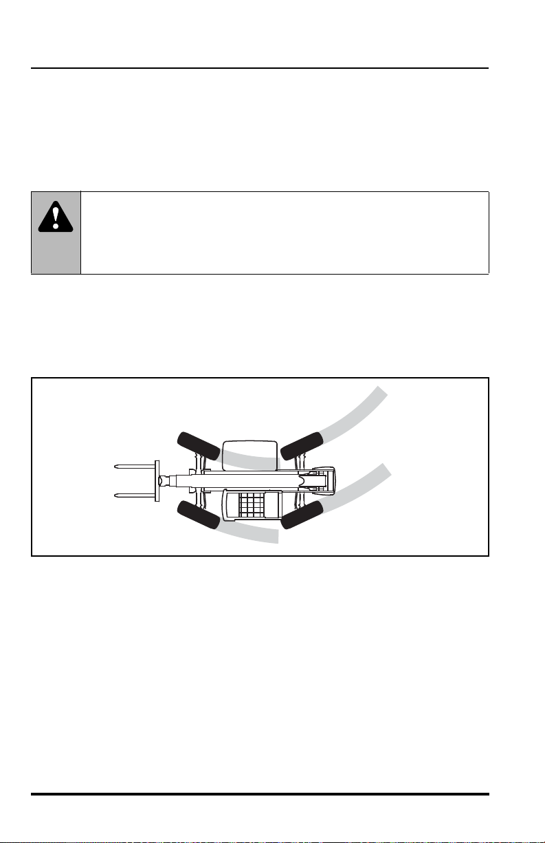
Operation
OS0280
Four Wheel Steer Indexing
If the vehicle does not drive “straight,” the steering could be “out of phase.”
Perform the “Four Wheel Steer Indexing Procedure” on page 244 to
synchronize the front and rear steering.
1. Four Wheel Steering
WARNING: NEVER use the Four Wheel Steering
Mode when traveling at high speed. Rapid turning in this mode
can cause tipover. Use only the Front Wheel Steering Mode at
higher speeds and slow the vehicle when turning.
The front wheels will steer in the direction that the steering wheel is turned;
the rear wheels will steer in the opposite direction. This steering mode
allows an extremely short turning radius and enables the rear wheels to
follow the tracking of the front wheels which can be an advantage in mud
and sand conditions.
80
Model MMV Rev. 10/11
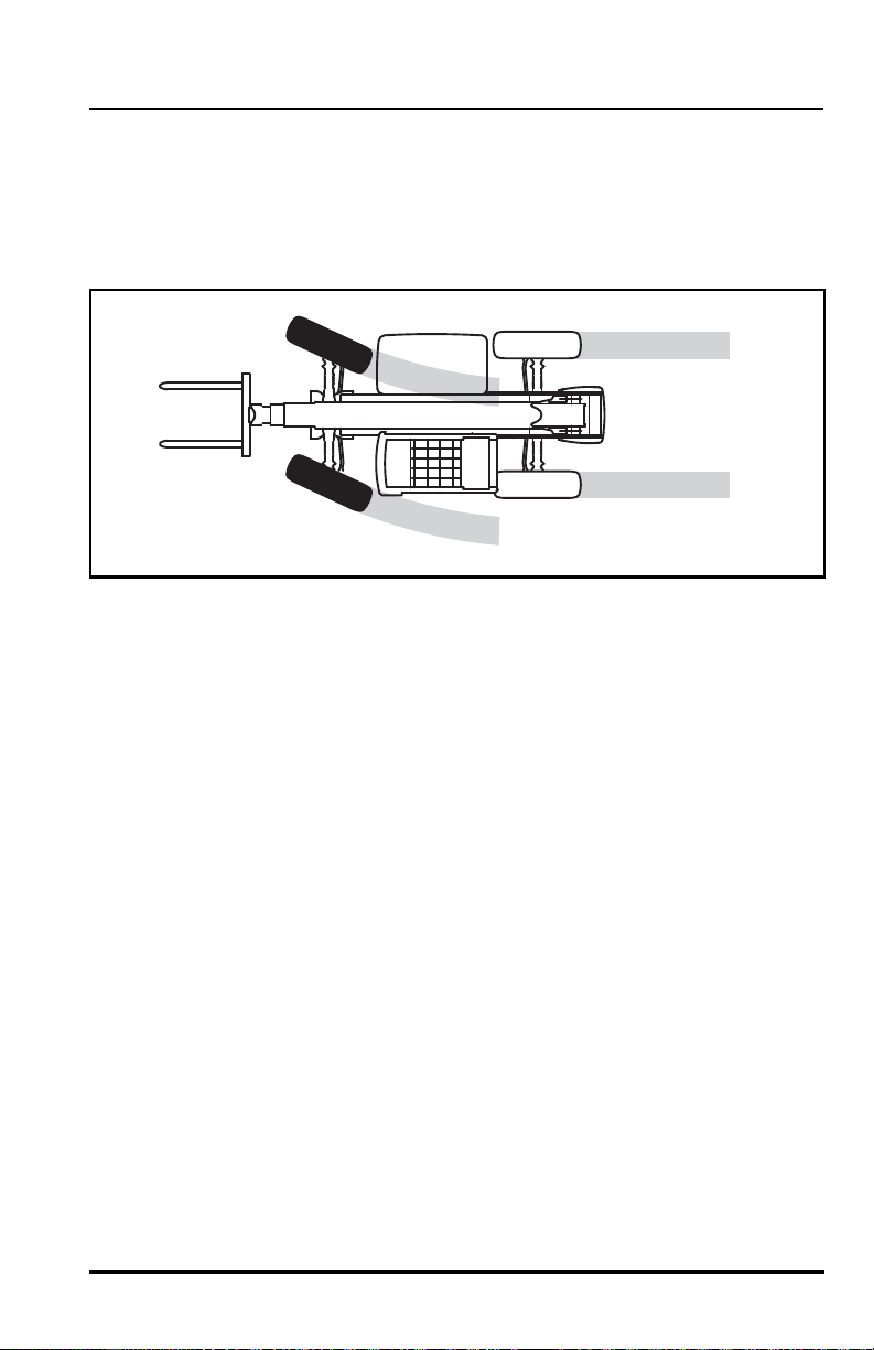
Operation
OS0290
2. Front Wheel Steering
The front wheels will steer in the direction that the steering wheel is turned.
The rear wheels will remain in a fixed forward position. This steering mode
should be used when loading or unloading the vehicle from a trailer and for
on-highway travel at higher speeds.
Model MMV Rev. 10/11
81
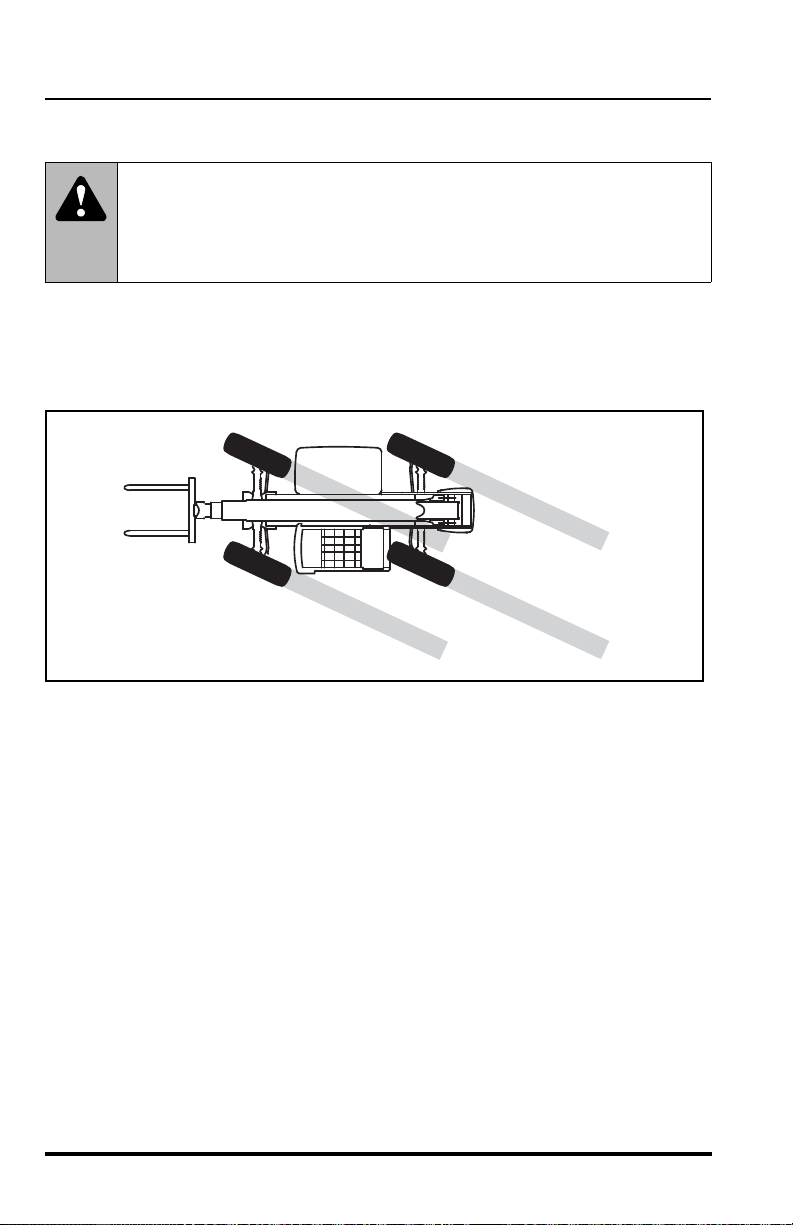
Operation
OS0310
3. Crab Steering
W ARNING: NEVER use the Crab Steering Mode when
traveling at high speed. Rapid turning in this mode can cause
tipover . Use only the Front Whe el Steering Mode at hi gher speeds
and slow the vehicle when turning.
All wheels will steer in the same direction that the steering wheel is turned.
This steering mode allows the operator to move the vehicle “sideways”
toward the landing point of a load. This is especially useful on a congested
worksite in order to line up at the exact spot in front of the loading location.
82
Model MMV Rev. 10/11
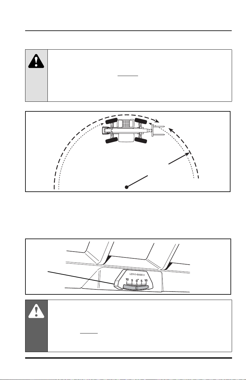
Maximum Fork Sweep
OS0323
1
OS0232
2
CAUTION: Allow for adequate clearance between
the attachment and other objects when turning.
The attachment extends beyond
ator must be aware of the maximum sweep (1) of the attachment
when turning in order to avoid hitting personnel and other objects
in the area.
Leveling the Vehicle
Operation
the end of the vehicle. The oper-
When placing a load while on a slope, use the frame sway control (see
MODE 3 page 37) to keep the vehicle level. The operator should observe
the frame level indicator (2) to assure that the vehicle is level at all times.
.
DANGER: Use of the frame sway control with the boom
raised above horizontal can cause tipover resulting in death or
serious personal injury . Always use the frame sway control to level
the vehicle before
cannot be leveled using the frame sway control, reposition the
vehicle.
Model MMV Rev. 10/11
raising the boom above horizontal. If the vehicle
83
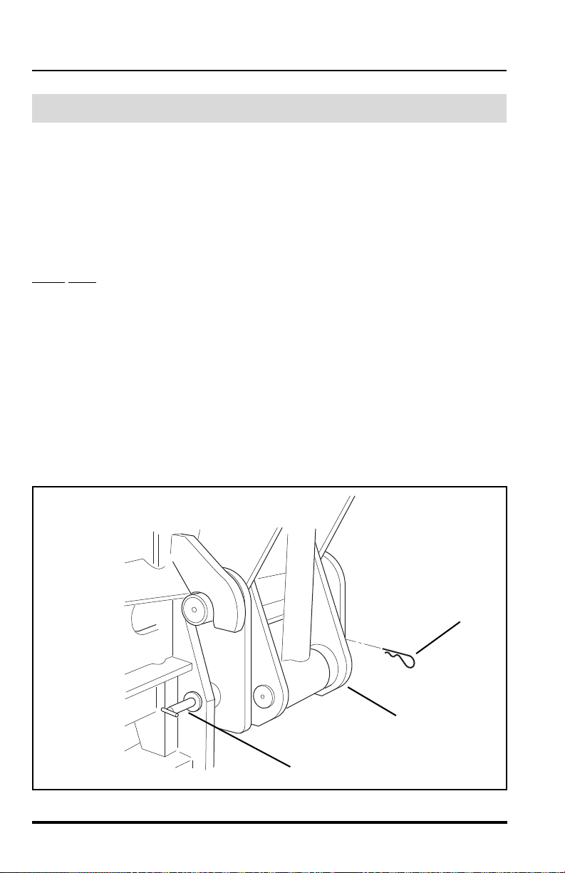
Operation
OM0970
3
5
4
Carriages
Quick Attach
This vehicle is equipped with a quick attach system for easy attachment
changing.
Attachment Removal
Be sure you are performing this procedure on level ground.
NOTE: Ensure the forks of the carriage being remo ve d ar e in a po sitio n
other
than fully shifted inboard or outboard to minimize trapped hydraulic
pressure.
1. Place the travel select lever in (N) NEUTRAL, come to a complete
stop, move the neutral lock lever to the (N) NEUTRAL LOCK position and engage the parking brake switch.
2. Extend the boom approximately 10 feet (3 me te rs ) an d tilt th e c arriage backward.
3. Exit the vehicle using both hand holds.
4. Remove the spring clip pin (3) from the quick attach pin (4) and pu ll
the pin out of the bottom of the quick att ach link (5).
84
Model MMV Rev. 10/11
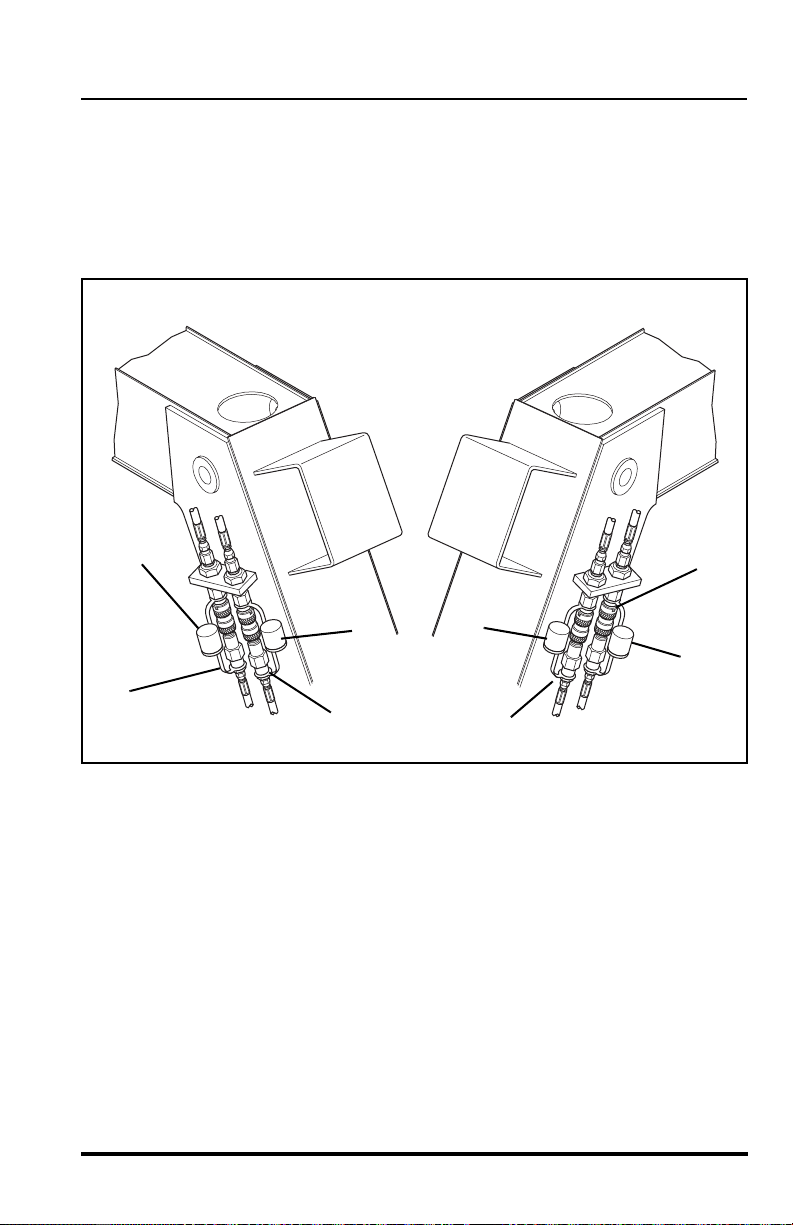
Operation
OM0930
1
5
2
3
4
5
5
5
5. Remove the four hydraulic quick disconnects between t he carriage
and the vehicle. Remove the disconnects in the following order:
Disconnect the RED (1) then the BLACK (2) on the left side. Disconnect the GREEN (3) then the YELLOW (4) on the right side.
6. Install the “Male” and “Female” protective caps (5) on all four quick
disconnects.
7. Return to the operators compartment, fasten the seat belt and
lower the attachment to the ground in a level position. Tilt the
attachment forward. This will rotate the quick attach link back away
from the attachment.
8. Lower and then retract the boom until the attach m en t pivot pins
have disconnected from the attachment.
Model MMV Rev. 10/11
85

Operation
OM0970
8
7
6
Attachment Reconnect
Be sure you are performing this procedure on level ground.
1. Position the vehicle directly behind the attachment to be mounted.
2. Tilt the quick attach backward.
3. Extend the boom approximately 10 feet (3 me te rs ) an d dr ive the
vehicle forward until the attachment pivot pins are below and
between the two hooks on the attachment .
4. Raise the boom until the attachment pivot pins have seated fully in
the hooks of the attachment.
5. Tilt the attachment up slightly. The quick attach link should be tight
against the rear of the attachment and the ho les in the link and the
attachment should be aligned.
6. Place the travel select lever in (N) NEUTRAL, move the neutral lock
lever to the (N) NEUTRAL LOCK position, engage the parking
brake switch and exit the vehicle using both hand holds.
7. Insert the quick attach pin (6) completely th ro ug h th e at tac hm e nt
and the quick attach link (7). Insert the spring clip pin (8) through
the quick attach pin.
86
Model MMV Rev. 10/11

Operation
OM0930
4
3
2
1
8. Remove the protective caps from the quick couplers. Connect the
quick couplers in the following order: Connect the YELLOW (1)
then the GREEN (2) on the right side. Connect t he BLACK (3) th en
the RED (4) on the left side.
9. In the event there is trapped pressure in one of t he carriage hydraulic hoses, connect the quick coupler(s) with a firm constant motion.
This will allow the (specially designed) male quick coupler to drain
the trapped pressure through to the female coupler and into the
hydraulic system.
10. Return to the cab, fasten the seat belt and resume operation.
Model MMV Rev. 10/11
WARNING: DO NOT operate this vehicle unless you
are in the seat with the seat belt fastened aroun d you. Death or
serious personal injury could result if the belt is not securely fastened.
87

Operation
OM1940
6
5
Transport Position - 11K Fork Carriage
Loading the 11K Carriage for Transport
Your vehicle will arrive with its 11K carriage (5) riding on the attached 7K
carriage (6). You must remove and store the 1 1K carriage if the 7K carriage
is to be used. Or, if the 11K carriage will first be placed in service, you will
remove the 11K carriage and store the 7K carriage, and then reattach the
11K carriage to the vehicle.
The aid of an assistant will be required to perform this task, because the
proximity of the 11K carriage alignment to the 7K carriage will be difficult to
determine from inside the cab.
88
Model MMV Rev. 10/11

Operation
1
OM1880
2
Removing the 1 1K Carriage from the 7K Carriage
1. Use the right fork shift switch (1) to move the right fork on the 7K
carriage to the right, just enough for the back of the right fork to
clear the weldment on the back of the 1 1K carr iage. Use the left fork
shift switch (2) to move the left fork on the 7K carriage to the left,
just far enough for the back of the left fork to clear the other weldment.
2. Ensure that the 11K carriage is positioned on a level surface for
proper storage.
3. Lower and level the 7K carriage until the 11K carriage just rests on
the ground.
4. Back the vehicle up until the 7K carriage forks are clear of the
unloaded 11K carriage.
Model MMV Rev. 10/11
89

Operation
OM1241
5
4
6
6
3
3
Installing the 11K Carriage on the 7K Carriage
IMPORTANT! Before installing the 11K carriage on the 7K carriage place
the four hoses (3) from the rear of the 11K carriage up and over the top of
the carriage. This will ensure that the hoses do not get pinched by the 7K
carriage during installation of the forks for tr ansport of the 11K carriage. Pull
the hoses toward the front of the carriage to remove all the slack fr om the
hoses. Let all four hoses hang down in front of the 11K carriage.
1. Ensure that the 11K carriage forks (4) are inboard of the openings
(5) in the carriage back for the 7K carriage forks to be inserted
through. If the 11K carriage forks interfere, attach the 11K carriage,
close the fork gap and remount the 7K carriag e.
2. Maneuver the vehicle so the 7K carriage is centered on the 11K
carriage.
3. Lower the 7K carriage so the forks are at the same he ig ht fr om the
ground as the openings (5) in the 11K carriage.
4. Maneuver the vehicle so the 7K carriage forks (6) go in the
intended openings (5) in the 11K carri age. The b ack of th e 11K carriage must be resting against the vertical area of the 7K forks.
90
Model MMV Rev. 10/11

Operation
1
OM1880
2
5. Use the right fork shift switch (1) to move the right fork on the 7K
carriage to the left, enough for the back of the right fork to rest
tightly against the weldment on the back of the 11K carriage. Use
the left fork shift switch (2) to move the left fork on the 7K carriage
to the right, enough for the back of the left fork t o rest tightly a gainst
the other weldment.
6. Place the travel selector in NEUTRAL (N) and engage the parking
brake.
7. Exit the operators compartment and visually confirm that both 7K
forks are fully engaged behind the weldments on the back of the
11K carriage.
8. Raise the boom and the 7K carriage into the travel position. The
11K carriage can now be transported.
Model MMV Rev. 10/11
91
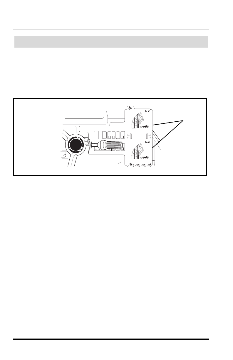
Operation
A
C
E
F
D
B
A
C
E
F
D
B
OM1950
3
Using the Capacity Chart
The individual capacity charts are located inside a booklet (3) on the right
side of the operator’s compartment. Capacity charts are provided to assist
the operator in determining how far in front, how high and at what angle a
specific load can be safely handled with this vehicle. Choose the correct
load chart for the size carriage being used and the tire pressu re being
utilized.
92
Model MMV Rev. 10/11
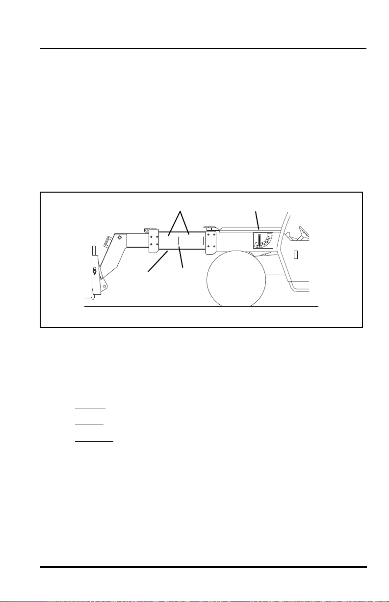
Operation
AB
OM1960
1
4
2
3
The vehicle is equipped with two indicators that will assist the operator in
determining how to accurately use the capacity chart. These indicators are:
• boom extend letters (1)
• boom angle indicator (2)
As the boom is extended, boom extend letters (1) and vertical dividin g lines
(3) become visible on the left side of the intermediate boom (4). These
letters and vertical lines indicate the point (zone) of boom extension and
correspond to the capacity chart. For example, when the boom extend “B”
first appears, the boom is at the point of boom extension corresponding to
an arc of line “B” on the capacity chart.
The boom angle indicator (2), located on the left side of t he outer boom,
indicates the angle of the boom and also corresponds with the angles
indicated on the capacity chart.
To accurately use the capacity chart, the operator must first determine three
important things:
1. Weight
2. Height
3. Distance
of the load being lifted.
of the structure where the load is to be placed.
where the load will ultimately be placed in front of the front
tires.
IMPORTANT! If operating the vehicle at 60 psi (414 kPa) or 45 psi
(310 kPa) reduced tire pressures, refer to “Load Capacity To Travel Speed
Tables” begining on page 94 for proper operating capacities and speeds.
ALWAYS refer to the proper load chart in the operators cab when working
with a load.
Model MMV Rev. 10/11
93

Operation
OM2260
Load Capacity To Travel Speed Tables
Use With 87 psi (600 kPa) - Full Tire Pressure
Recommended Gear/Speed for Various Load/Travel Conditions
(Forward Direction Only)
7 K Fork Carriage
Load Size Surface Gear Speed
No Load Smooth 4th* 0 to 20 mph (0 to 32 km/h)
Improved 3rd 0 to 14 mph (0 to 23 km/h)
Rough 2nd 0 to 6 mph (0 to 9,7 km/h)
Load Smooth 3rd 0 to 14 mph (0 to 23 km/h)
up to 3,500 lbs Improved 2nd 0 to 6 mph (0 to 9,7 km/h)
(up to 1.588 kg)
Load Smooth 2nd 0 to 6 mph (0 to 9,7 km/h)
3,500 to 7,000 lbs Improved 2nd 0 to 6 mph (0 to 9,7 km/h)
(1.588 to 3.175 kg)
Rough 2nd 0 to 6 mph (0 to 9,7 km/h)
Rough 1st 0 to 3.5 mph (0 to 5,6 km/h)
11 K Fork Carriage
Load Size Surface Gear Speed
No Load Smooth 4th* 0 to 20 mph (0 to 32 km/h)
Improved 3rd 0 to 14 mph (0 to 23 km/h)
Rough 2nd 0 to 6 mph (0 to 9,7 km/h)
Load Smooth 3rd 0 to 14 mph (0 to 23 km/h)
up to 4,500 lbs Improved 2nd 0 to 6 mph (0 to 9,7 km/h)
(up to 2.041 kg)
Load Smooth 2nd 0 to 6 mph (0 to 9,7 km/h)
4,500 to 11,00 0 lbs Improved 2nd 0 to 6 mph (0 to 9,7 km/h)
(2.041 to 4.989 kg)
Rough 2nd 0 to 6 mph (0 to 9,7 km/h)
Rough 1st 0 to 3.5 mph (0 to 5,6 km/h)
*NEVER travel in 4th gear when carrying a load.
94
Model MMV Rev. 10/11
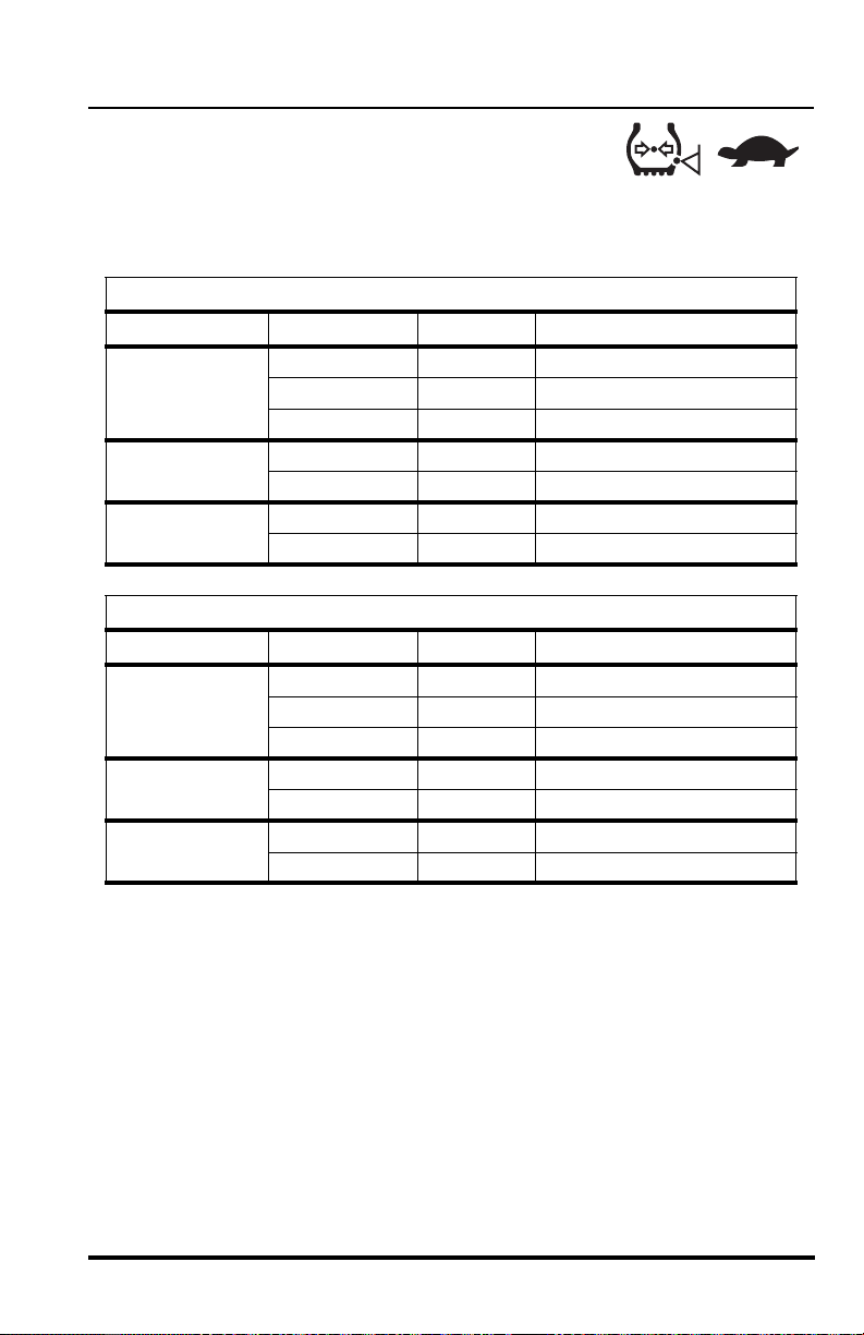
Operation
OM2250
OM2320
Use With 60 psi (414 kPa) - Reduced Tire
Pressure
Recommended Gear/Speed for Various Load/Travel Conditions
(Forward Direction Only)
7 K Fork Carriage
Load Size Surface Gear Speed
No Load Smooth 3rd 0 to 14 mph (0 to 23 km/h)
Improved 2nd 0 to 6 mph (0 to 9,7 km/h)
Rough 1st 0 to 3.5 mph (0 to 5,6 km/h)
Up to 2,000 lbs Improved 2nd 0 to 6 mph (0 to 9,7 km/h)
(up to 907 kg)
2,000 to 4,000 lbs Improved 2nd 0 to 6 mph (0 to 9,7 km/h)
(907 to 1.814 kg)
Load Size Surface Gear Speed
No Load Smooth 3rd 0 to 14 mph (0 to 23 km/h)
Up to 2,000 lbs Improved 2nd 0 to 6 mph (0 to 9,7 km/h)
(up to 907 kg)
2,000 to 5,500 lbs Improved 2nd 0 to 6 mph (0 to 9,7 km/h)
(907 to 2.495 kg)
Rough 1st 0 to 3.5 mph (0 to 5,6 km/h)
Rough 1st 0 to 3.5 mph (0 to 5,6 km/h)
11 K Fork Carriage
Improved 2nd 0 to 6 mph (0 to 9,7 km/h)
Rough 1st 0 to 3.5 mph (0 to 5,6 km/h)
Rough 1st 0 to 3.5 mph (0 to 5,6 km/h)
Rough 1st 0 to 3.5 mph (0 to 5,6 km/h)
NEVER travel in 4th gear when operating at this tire pressure.
Model MMV Rev. 10/11
95
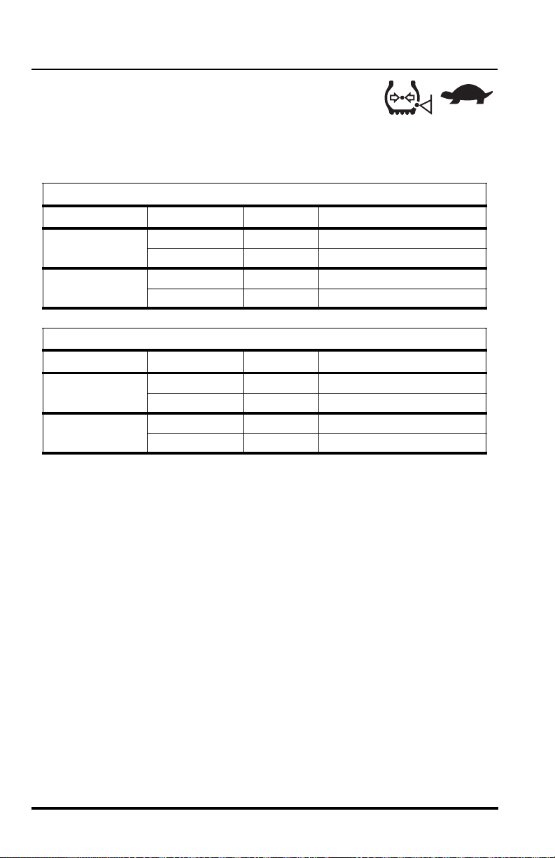
Operation
OM2250
OM2320
Use With 45 psi (310 kPa) - Reduced Tire
Pressure
Recommended Gear/Speed for Various Load/Travel Conditions
(Forward Direction Only)
7 K Fork Carriage
Load Size Surface Gear Speed
No Load Improved 2nd 0 to 6 mph (0 to 9,7 km/h)
Rough 1st 0 to 3.5 mph (0 to 5,6 km/h)
Up to 1,000 lbs Improved 2nd 0 to 6 mph (0 to 9,7 km/h)
(up to 454 kg)
Load Size Surface Gear Speed
No Load Improved 2nd 0 to 6 mph (0 to 9,7 km/h)
Up to 2,000 lbs Improved 2nd 0 to 6 mph (0 to 9,7 km/h)
(up to 907 kg)
Rough 1st 0 to 3.5 mph (0 to 5,6 km/h)
11 K Fork Carriage
Rough 1st 0 to 3.5 mph (0 to 5,6 km/h)
Rough 1st 0 to 3.5 mph (0 to 5,6 km/h)
NEVER travel in 3rd or 4th gear when operating at this tire pressure.
96
Model MMV Rev. 10/11
 Loading...