


Service Manual
Model
6036
S/N 14834 & After
8990416
Revised February 11, 2005


EFFECTIVITY PAGE
September, 2001 - Original issue.
February 11, 2005 - B - Replaced all branding with JLG.
Model 6036 Legacy

EFFECTIVITY PAGE
Model 6036 Legacy

SECTION CONTENTS
Section Subject Page
Section 1
Safety Practices . . . . . . . . . . . . . . . . . . . . . . . . . . . . . . . . . . . . . . . . . . . . . . . . . . . . . . . 1.1
1.1 Introduction . . . . . . . . . . . . . . . . . . . . . . . . . . . . . . . . . . . . . . . . . . . . . . . . . . . . . . . . . . 1.2
1.2 Owners/Operators Manual . . . . . . . . . . . . . . . . . . . . . . . . . . . . . . . . . . . . . . . . . . . . . . 1.2
1.3 Training Mechanics as Operators . . . . . . . . . . . . . . . . . . . . . . . . . . . . . . . . . . . . . . . . . 1.3
1.4 Safety Information . . . . . . . . . . . . . . . . . . . . . . . . . . . . . . . . . . . . . . . . . . . . . . . . . . . . . 1.3
1.5 Accident Prevention Tag Usage . . . . . . . . . . . . . . . . . . . . . . . . . . . . . . . . . . . . . . . . . . 1.4
1.6 Safety Instructions. . . . . . . . . . . . . . . . . . . . . . . . . . . . . . . . . . . . . . . . . . . . . . . . . . . . . 1.5
1.7 Emergency Exit Rear Window . . . . . . . . . . . . . . . . . . . . . . . . . . . . . . . . . . . . . . . . . . . 1.6
1.8 Hazard/Emergency Information Decals . . . . . . . . . . . . . . . . . . . . . . . . . . . . . . . . . . . . 1.7
Section 2
General Information and Specifications . . . . . . . . . . . . . . . . . . . . . . . . . . . . . . . . . . . . 2.1
2.1 6036 Component Terminology . . . . . . . . . . . . . . . . . . . . . . . . . . . . . . . . . . . . . . . . . . . 2.3
2.2 Introduction . . . . . . . . . . . . . . . . . . . . . . . . . . . . . . . . . . . . . . . . . . . . . . . . . . . . . . . . . . 2.4
2.3 Torques . . . . . . . . . . . . . . . . . . . . . . . . . . . . . . . . . . . . . . . . . . . . . . . . . . . . . . . . . . . . . 2.5
2.4 Metric Conversion Factors. . . . . . . . . . . . . . . . . . . . . . . . . . . . . . . . . . . . . . . . . . . . . . . 2.6
2.5 Specifications . . . . . . . . . . . . . . . . . . . . . . . . . . . . . . . . . . . . . . . . . . . . . . . . . . . . . . . . 2.8
2.6 Fluids, Lubricants and Capacities . . . . . . . . . . . . . . . . . . . . . . . . . . . . . . . . . . . . . . . . . 2.16
2.7 Cleaning . . . . . . . . . . . . . . . . . . . . . . . . . . . . . . . . . . . . . . . . . . . . . . . . . . . . . . . . . . . . 2.20
2.8 Replacement . . . . . . . . . . . . . . . . . . . . . . . . . . . . . . . . . . . . . . . . . . . . . . . . . . . . . . . . . 2.21
2.9 Hoses and Tubes . . . . . . . . . . . . . . . . . . . . . . . . . . . . . . . . . . . . . . . . . . . . . . . . . . . . . 2.21
2.10 Bearings . . . . . . . . . . . . . . . . . . . . . . . . . . . . . . . . . . . . . . . . . . . . . . . . . . . . . . . . . . . . 2.21
2.11 Pressure Testing and Adjustment . . . . . . . . . . . . . . . . . . . . . . . . . . . . . . . . . . . . . . . . . 2.22
2.12 After Service Startup and Checks. . . . . . . . . . . . . . . . . . . . . . . . . . . . . . . . . . . . . . . . . 2.22
Section 3
Boom . . . . . . . . . . . . . . . . . . . . . . . . . . . . . . . . . . . . . . . . . . . . . . . . . . . . . . . . . . . 3.1
3.1 Boom System Component Terminology . . . . . . . . . . . . . . . . . . . . . . . . . . . . . . . . . . . . 3.2
3.2 Boom System . . . . . . . . . . . . . . . . . . . . . . . . . . . . . . . . . . . . . . . . . . . . . . . . . . . . . . . . 3.3
3.3 Boom Assembly Maintenance. . . . . . . . . . . . . . . . . . . . . . . . . . . . . . . . . . . . . . . . . . . . 3.3
3.4 Quick Attach Assembly . . . . . . . . . . . . . . . . . . . . . . . . . . . . . . . . . . . . . . . . . . . . . . . . . 3.59
3.5 Troubleshooting. . . . . . . . . . . . . . . . . . . . . . . . . . . . . . . . . . . . . . . . . . . . . . . . . . . . . . . 3.61
Section 4
Cab and Covers . . . . . . . . . . . . . . . . . . . . . . . . . . . . . . . . . . . . . . . . . . . . . . . . . . . . . . . . 4.1
4.1 Operator’s Cab and Covers Component Terminology. . . . . . . . . . . . . . . . . . . . . . . . . . 4.2
4.2 Operator’s Cab . . . . . . . . . . . . . . . . . . . . . . . . . . . . . . . . . . . . . . . . . . . . . . . . . . . . . . . 4.3
4.3 Open Cab Components . . . . . . . . . . . . . . . . . . . . . . . . . . . . . . . . . . . . . . . . . . . . . . . . 4.4
4.4 Enclosed Cab (Optional) Components . . . . . . . . . . . . . . . . . . . . . . . . . . . . . . . . . . . . . 4.19
4.5 Cab Removal. . . . . . . . . . . . . . . . . . . . . . . . . . . . . . . . . . . . . . . . . . . . . . . . . . . . . . . . . 4.25
4.6 Cab Installation . . . . . . . . . . . . . . . . . . . . . . . . . . . . . . . . . . . . . . . . . . . . . . . . . . . . . . . 4.29
4.7 Access Panels and Covers . . . . . . . . . . . . . . . . . . . . . . . . . . . . . . . . . . . . . . . . . . . . . . 4.32
Model 6036 Legacy
i

Section Subject Page
Section 5
Axles, Drive Shafts, Wheels and Tires . . . . . . . . . . . . . . . . . . . . . . . . . . . . . . . . . . . . . . 5.1
5.1 Axle, Drive Shaft and Wheel Component Terminology . . . . . . . . . . . . . . . . . . . . . . . . . 5.2
5.2 General Information . . . . . . . . . . . . . . . . . . . . . . . . . . . . . . . . . . . . . . . . . . . . . . . . . . . . 5.3
5.3 Axle Assemblies. . . . . . . . . . . . . . . . . . . . . . . . . . . . . . . . . . . . . . . . . . . . . . . . . . . . . . . 5.3
5.4 Drive Shafts . . . . . . . . . . . . . . . . . . . . . . . . . . . . . . . . . . . . . . . . . . . . . . . . . . . . . . . . . . 5.15
5.5 Wheels and Tires . . . . . . . . . . . . . . . . . . . . . . . . . . . . . . . . . . . . . . . . . . . . . . . . . . . . . . 5.21
Section 6
Transmission: ZF 4 WG-98 TC . . . . . . . . . . . . . . . . . . . . . . . . . . . . . . . . . . . . . . . . . . . . 6.1
6.1 Transmission Assembly Component Terminology . . . . . . . . . . . . . . . . . . . . . . . . . . . . . 6.2
6.2 Transmission Description . . . . . . . . . . . . . . . . . . . . . . . . . . . . . . . . . . . . . . . . . . . . . . . . 6.3
6.3 Transmission Operation . . . . . . . . . . . . . . . . . . . . . . . . . . . . . . . . . . . . . . . . . . . . . . . . . 6.3
6.4 Transmission Serial Number . . . . . . . . . . . . . . . . . . . . . . . . . . . . . . . . . . . . . . . . . . . . . 6.3
6.5 Transmission Specifications . . . . . . . . . . . . . . . . . . . . . . . . . . . . . . . . . . . . . . . . . . . . . . 6.4
6.6 Transmission Maintenance. . . . . . . . . . . . . . . . . . . . . . . . . . . . . . . . . . . . . . . . . . . . . . . 6.4
6.7 Transmission Replacement . . . . . . . . . . . . . . . . . . . . . . . . . . . . . . . . . . . . . . . . . . . . . . 6.6
6.8 Towing a Disabled Vehicle . . . . . . . . . . . . . . . . . . . . . . . . . . . . . . . . . . . . . . . . . . . . . . . 6.13
6.9 Troubleshooting . . . . . . . . . . . . . . . . . . . . . . . . . . . . . . . . . . . . . . . . . . . . . . . . . . . . . . .6.14
Section 7
Engine: Cummins 4BT3.9 . . . . . . . . . . . . . . . . . . . . . . . . . . . . . . . . . . . . . . . . . . . . . . . . 7.1
7.1 Introduction . . . . . . . . . . . . . . . . . . . . . . . . . . . . . . . . . . . . . . . . . . . . . . . . . . . . . . . . . . 7.2
7.2 Safety Information . . . . . . . . . . . . . . . . . . . . . . . . . . . . . . . . . . . . . . . . . . . . . . . . . . . . . 7.4
7.3 Engine Serial Number . . . . . . . . . . . . . . . . . . . . . . . . . . . . . . . . . . . . . . . . . . . . . . . . . . 7.6
7.4 Specifications and Maintenance Information . . . . . . . . . . . . . . . . . . . . . . . . . . . . . . . . . 7.6
7.5 Standard Practices . . . . . . . . . . . . . . . . . . . . . . . . . . . . . . . . . . . . . . . . . . . . . . . . . . . . . 7.6
7.6 Engine Cooling System . . . . . . . . . . . . . . . . . . . . . . . . . . . . . . . . . . . . . . . . . . . . . . . . . 7.7
7.7 Engine Electrical System . . . . . . . . . . . . . . . . . . . . . . . . . . . . . . . . . . . . . . . . . . . . . . . . 7.14
7.8 Fuel System . . . . . . . . . . . . . . . . . . . . . . . . . . . . . . . . . . . . . . . . . . . . . . . . . . . . . . . . . .7.15
7.9 Engine Exhaust System . . . . . . . . . . . . . . . . . . . . . . . . . . . . . . . . . . . . . . . . . . . . . . . . . 7.23
7.10 Air Cleaner Assembly. . . . . . . . . . . . . . . . . . . . . . . . . . . . . . . . . . . . . . . . . . . . . . . . . . . 7.24
7.11 Engine Replacement . . . . . . . . . . . . . . . . . . . . . . . . . . . . . . . . . . . . . . . . . . . . . . . . . . . 7.25
7.12 Engine Storage . . . . . . . . . . . . . . . . . . . . . . . . . . . . . . . . . . . . . . . . . . . . . . . . . . . . . . .7.37
7.13 Troubleshooting . . . . . . . . . . . . . . . . . . . . . . . . . . . . . . . . . . . . . . . . . . . . . . . . . . . . . . .7.38
Section 8
Hydraulic System . . . . . . . . . . . . . . . . . . . . . . . . . . . . . . . . . . . . . . . . . . . . . . . . . . . . . . . 8.1
8.1 Hydraulic Component Terminology . . . . . . . . . . . . . . . . . . . . . . . . . . . . . . . . . . . . . . . . 8.3
8.2 Safety Information . . . . . . . . . . . . . . . . . . . . . . . . . . . . . . . . . . . . . . . . . . . . . . . . . . . . . 8.4
8.3 Specifications . . . . . . . . . . . . . . . . . . . . . . . . . . . . . . . . . . . . . . . . . . . . . . . . . . . . . . . . . 8.5
8.4 Hydraulic Fluid . . . . . . . . . . . . . . . . . . . . . . . . . . . . . . . . . . . . . . . . . . . . . . . . . . . . . . . .8.5
8.5 Hoses, Tube Lines, Fittings, Etc. . . . . . . . . . . . . . . . . . . . . . . . . . . . . . . . . . . . . . . . . . . 8.6
8.6 Hydraulic Pressure Diagnosis . . . . . . . . . . . . . . . . . . . . . . . . . . . . . . . . . . . . . . . . . . . . 8.7
8.7 Hydraulic System Testing. . . . . . . . . . . . . . . . . . . . . . . . . . . . . . . . . . . . . . . . . . . . . . . . 8.10
8.8 Hydraulic Circuits and Troubleshooting . . . . . . . . . . . . . . . . . . . . . . . . . . . . . . . . . . . . . 8.13
8.9 Four-Wheel Steer Indexing Procedure . . . . . . . . . . . . . . . . . . . . . . . . . . . . . . . . . . . . . . 8.58
8.10 Hydraulic Reservoir . . . . . . . . . . . . . . . . . . . . . . . . . . . . . . . . . . . . . . . . . . . . . . . . . . . . 8.60
8.11 Hydraulic System Pump . . . . . . . . . . . . . . . . . . . . . . . . . . . . . . . . . . . . . . . . . . . . . . . . . 8.61
8.12 Valves and Manifolds . . . . . . . . . . . . . . . . . . . . . . . . . . . . . . . . . . . . . . . . . . . . . . . . . . . 8.68
8.13 Hydraulic Cylinders . . . . . . . . . . . . . . . . . . . . . . . . . . . . . . . . . . . . . . . . . . . . . . . . . . . . 8.100
ii
Model 6036 Legacy

Section Subject Page
Section 9
Electrical System . . . . . . . . . . . . . . . . . . . . . . . . . . . . . . . . . . . . . . . . . . . . . . . . . . . . . . 9.1
9.1 Electrical Component Terminology . . . . . . . . . . . . . . . . . . . . . . . . . . . . . . . . . . . . . . . . 9.3
9.2 Service Warnings . . . . . . . . . . . . . . . . . . . . . . . . . . . . . . . . . . . . . . . . . . . . . . . . . . . . . 9.5
9.3 Specifications . . . . . . . . . . . . . . . . . . . . . . . . . . . . . . . . . . . . . . . . . . . . . . . . . . . . . . . . 9.5
9.4 Effective Ground Connections. . . . . . . . . . . . . . . . . . . . . . . . . . . . . . . . . . . . . . . . . . . . 9.6
9.5 Wiring Harnesses . . . . . . . . . . . . . . . . . . . . . . . . . . . . . . . . . . . . . . . . . . . . . . . . . . . . . 9.6
9.6 Fuses and Relays . . . . . . . . . . . . . . . . . . . . . . . . . . . . . . . . . . . . . . . . . . . . . . . . . . . . . 9.8
9.7 Electrical System Troubleshooting . . . . . . . . . . . . . . . . . . . . . . . . . . . . . . . . . . . . . . . . 9.10
9.8 Transmission Gear Selection Troubleshooting . . . . . . . . . . . . . . . . . . . . . . . . . . . . . . . 9.40
9.9 Dash Panel Warning Indicator Troubleshooting . . . . . . . . . . . . . . . . . . . . . . . . . . . . . . 9.48
9.10 Engine Start Circuit . . . . . . . . . . . . . . . . . . . . . . . . . . . . . . . . . . . . . . . . . . . . . . . . . . . . 9.57
9.11 Charging Circuit . . . . . . . . . . . . . . . . . . . . . . . . . . . . . . . . . . . . . . . . . . . . . . . . . . . . . . 9.59
9.12 Electrical System Components . . . . . . . . . . . . . . . . . . . . . . . . . . . . . . . . . . . . . . . . . . . 9.65
9.13 Window Wiper/Washer (Option) . . . . . . . . . . . . . . . . . . . . . . . . . . . . . . . . . . . . . . . . . . 9.70
9.14 Cab Heater and Fan (Option) . . . . . . . . . . . . . . . . . . . . . . . . . . . . . . . . . . . . . . . . . . . . 9.75
9.15 Switches and Solenoids . . . . . . . . . . . . . . . . . . . . . . . . . . . . . . . . . . . . . . . . . . . . . . . . 9.76
Section 10
Index . . . . . . . . . . . . . . . . . . . . . . . . . . . . . . . . . . . . . . . . . . . . . . . . . . . . . . . . . . . 10.1
Accident Prevention Tags
Model 6036 Legacy
iii

Section Subject Page
This Page Intentionally Left Blank
iv
Model 6036 Legacy

Section 1
Safety Practices
Contents
PARAGRAPH TITLE PAGE
1.1 Introduction . . . . . . . . . . . . . . . . . . . . . . . . . . . . . . . . . . . . . . . . . . . . . . . . . . . . . . . 1.2
1.2 Owners/Operators Manual . . . . . . . . . . . . . . . . . . . . . . . . . . . . . . . . . . . . . . . . . . . 1.2
1.3 Training Mechanics as Operators . . . . . . . . . . . . . . . . . . . . . . . . . . . . . . . . . . . . . 1.3
1.4 Safety Information. . . . . . . . . . . . . . . . . . . . . . . . . . . . . . . . . . . . . . . . . . . . . . . . . . 1.3
1.4.1 Safety Alert Symbol . . . . . . . . . . . . . . . . . . . . . . . . . . . . . . . . . . . . . . . . . 1.3
1.4.2 Hazard Statements . . . . . . . . . . . . . . . . . . . . . . . . . . . . . . . . . . . . . . . . . . 1.4
1.5 Accident Prevention Tag Usage. . . . . . . . . . . . . . . . . . . . . . . . . . . . . . . . . . . . . . . 1.4
1.6 Safety Instructions . . . . . . . . . . . . . . . . . . . . . . . . . . . . . . . . . . . . . . . . . . . . . . . . . 1.5
1.6.1 Personal Hazards . . . . . . . . . . . . . . . . . . . . . . . . . . . . . . . . . . . . . . . . . . . 1.5
1.6.2 Equipment Hazards. . . . . . . . . . . . . . . . . . . . . . . . . . . . . . . . . . . . . . . . . . 1.5
1.6.3 General Hazards . . . . . . . . . . . . . . . . . . . . . . . . . . . . . . . . . . . . . . . . . . . . 1.6
1.6.4 Operational Hazards . . . . . . . . . . . . . . . . . . . . . . . . . . . . . . . . . . . . . . . . . 1.6
1.7 Emergency Exit Rear Window . . . . . . . . . . . . . . . . . . . . . . . . . . . . . . . . . . . . . . . . 1.6
1.8 Hazard/Emergency Information Decals. . . . . . . . . . . . . . . . . . . . . . . . . . . . . . . . . 1.7
Model 6036 Legacy
1.1
Safety Practices
1.1 INTRODUCTION
JLG products meet all applicable industry safety standards. JLG actively promotes safe practices in the use
and maintenance of its products through training
programs, instructional manuals and the pro-active efforts
of all employees involved in engineering, design,
manufacture, marketing and service.
This manual is designed to provide service technicians
with complete information on the maintenance and repair
of the Sky Trak Model 6036 Legacy Telescopic Material
Handler.
Particular effort has been made to produce a manual to
serve as a reference handbook for the experienced
service technician, but also provide essential step-bystep procedures for the professional development of the
less experienced person. Remember, even the best
manual in the world is no substitute for an appropriate
education, skill development that comes through
experience alone, safety, wise and judicious
discernment, and ultimately, proper performance of
service procedures.
This service manual provides general directions for
accomplishing service and repair procedures with tested,
effective techniques. Following the procedures in this
manual will help assure safety and equipment reliability.
Read, understand and follow the information in this
manual, and obey all locally approved safety practices,
procedures, rules, codes, regulations and laws. Prior to
performing any maintenance on the vehicle, consider all
factors, circumstances and conditions which can have an
effect upon the safety of personnel and equipment, and
take appropriate action to ensure the safety of all
involved.
These instructions cannot cover all details or variations in
the equipment, procedures or processes described, nor
provide directions for meeting every possible contingency
during operation, maintenance or testing. When additional
information is desired to satisfy a situation not covered
sufficiently, consult the local JLG Authorized Service
Center (ASC) or the JLG Service Department at 1-877-554-
5438 (Domestic) or 1-717-485-5161 (Internationally).
Many factors contribute to unsafe conditions:
carelessness, fatigue, overload, inattentiveness,
unfamiliarity, even drugs and alcohol, among others.
Although equipment damage can usually be repaired in a
brief period of time, death and irreparable injury are
permanent. For optimal safety, encourage everyone to
think, and to act, safely.
Appropriate service methods and proper repair
procedures are essential for the safety of the individual
doing the work, for the safety of the operator, and for the
safe, reliable operation of the vehicle.
Provisions for supplementary information are made by
JLG in the form of Service Bulletins, Service Campaigns,
Service Training Schools, the JLG website, other literature, and through updates to the manual itself. Comments
and suggestions for improvement are welcome and encouraged.
All information, illustrations and specifications contained
in this manual are based on the latest product information
available at the time of publication approval. JLG reserves the right to make changes and improvements to
its products, and to discontinue the manufacture of any
product, at its discretion at any time without public notice
or obligation.
1.2 OWNERS/OPERATORS MANUAL
The vehicle must be driven and operated as a
consequence of, or when performing, service,
maintenance and test procedures. The service technician
must, therefore, thoroughly read, understand and follow
the Sky Trak Model 6036 Legacy Telescopic Material
Handler Owners/Operators Manual.
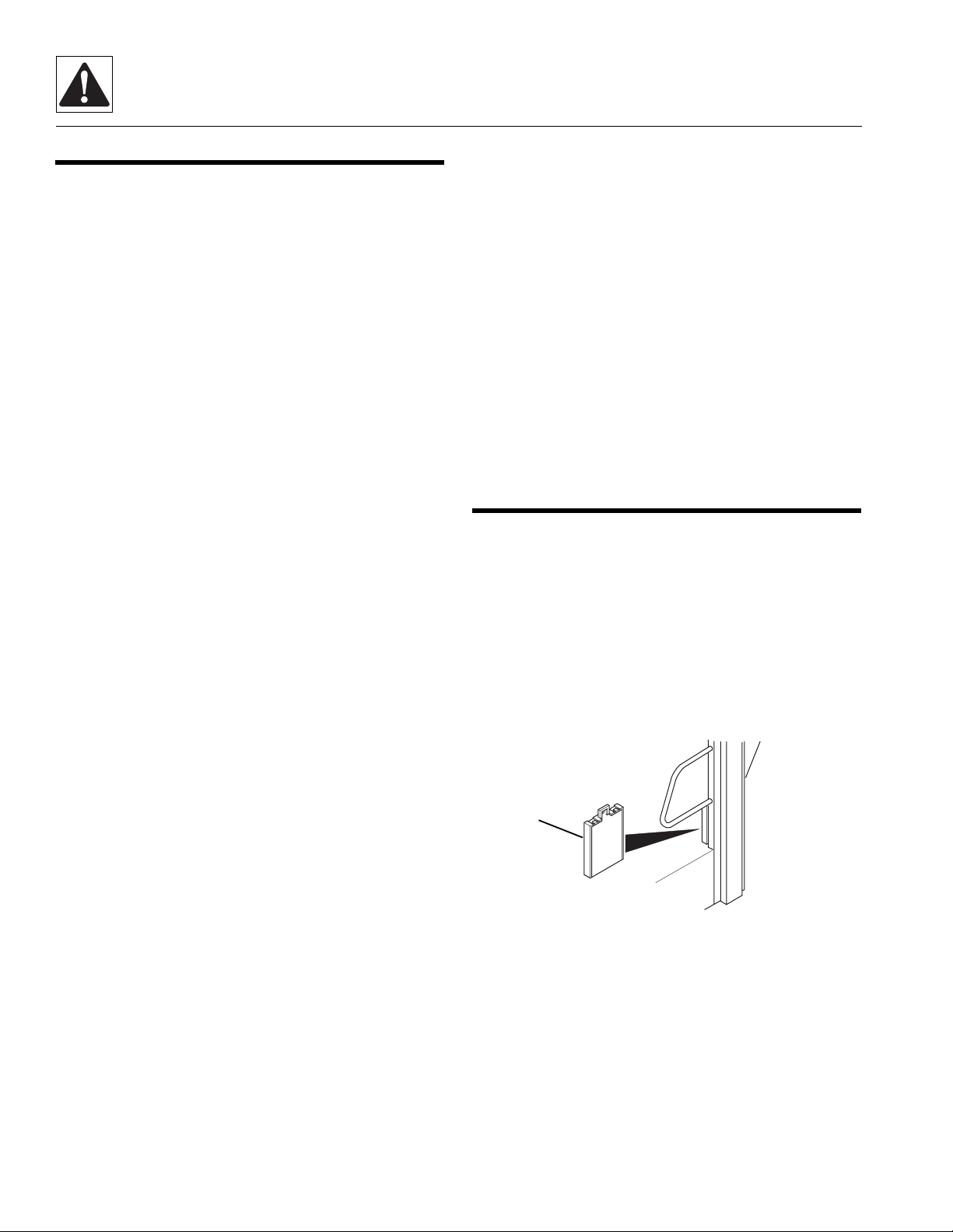
An owners/operators manual is supplied with each
vehicle and must be kept in the owners/operators manual
holder (Fig. 1-1, 1) located on the cab post to the left and
below the operator’s seat.
1
MH0770
Figure 1- 1 The Owners/Operators Manual Holder
In the event that the owners/operators manual is missing,
consult the local JLG Authorized Service Center (ASC) or
the JLG Service Department before proceeding.
1.2
Model 6036 Legacy

Safety Practices
1.3 TRAINING MECHANICS AS
OPERATORS
Because it is necessary to move the vehicle to service or
maintain the vehicle, it is necessary that all mechanics
are OSHA trained and certified as operators. A mechanic
trained in the proper operation of the vehicle can better
determine whether all functions are operating correctly.
At the time of original purchase, the purchaser of this
vehicle was instructed by the seller on its proper use.
When this vehicle is to be serviced or maintained by
someone other than the purchaser, make certain that the
mechanic is trained, in accordance with the OSHA
regulations listed in the NOTICE below, and reads and
understands the SKY TRAK Model 6036 Legacy
Telescopic Material Handler Owners/Operators Manual
before
operating or maintaining the vehicle.
NOTICE: Under OSHA rules, it is the responsibility of the
employer to provide operator training. Successful
completion and certification of Safety Training for Rough
Terrain Forklifts is required. Operator Training Kits are
available by calling the Ken Cook Company at (414) 466-
6060. An order form for these kits is available through our
website, http://www.jlg.com.
In addition, make sure that the mechanic has completed
a walk-around inspection of the vehicle, is familiar with all
decals and/or decal plates on the vehicle, and has
demonstrated the correct use of all controls.
1.4 SAFETY INFORMATION
The following information provides general safety
instructions, including examples of hazard statements
with signal words, notification of hazards, methods to
help avoid hazards and the consequences of failing to
follow the safety information. To avoid possible death or
injury, carefully read and follow all safety messages. Fully
understand the potential causes of death or injury.
In the event of an accident, know where to obtain medical
assistance and how to use a first-aid kit and fire
extinguisher/fire suppression system. Keep emergency
telephone numbers (fire department, ambulance, rescue
squad/paramedics, police department, etc.) nearby. If
working alone, check with another person routinely to
help ensure personal safety.
The information in this manual does not replace any other
safety rules or proper judgment. Governmental
authorities and employers also have their own sets of
rules, codes, regulations and laws. Before starting work
at a site, check with the supervisor or safety coordinator
and ask about the safety policy. Learn the safety
requirements in effect before operating, maintaining,
servicing or testing the vehicle. Safety depends on
following safety requirements.
1.4.1 Safety Alert Symbol
The exclamation mark within a triangle is the Safety Alert
Symbol.
Model 6036 Legacy
OP0330
This symbol means “Attention! Become Alert! Your
Safety Is Involved!” The symbol is used to attract
attention to safety hazards found on the vehicle safety
decals and throughout this manual.
1.3
Safety Practices
1.4.2 Hazard Statements
Signal words and messages are used in conjunction with
the safety alert symbol to create hazard statements.
These hazard statements convey important information
about safety.
Four types of hazard statements are used in this manual.
Each statement indicates the existence and degree of
relative risk of the hazard described within the statement
that follows the signal word.
Explanations of the types of hazard statements are as
follows:
DANGER:
The signal word “DANGER” indicates an imminently
hazardous situation which, if not avoided, will result in
death or serious injury.
WARNING:
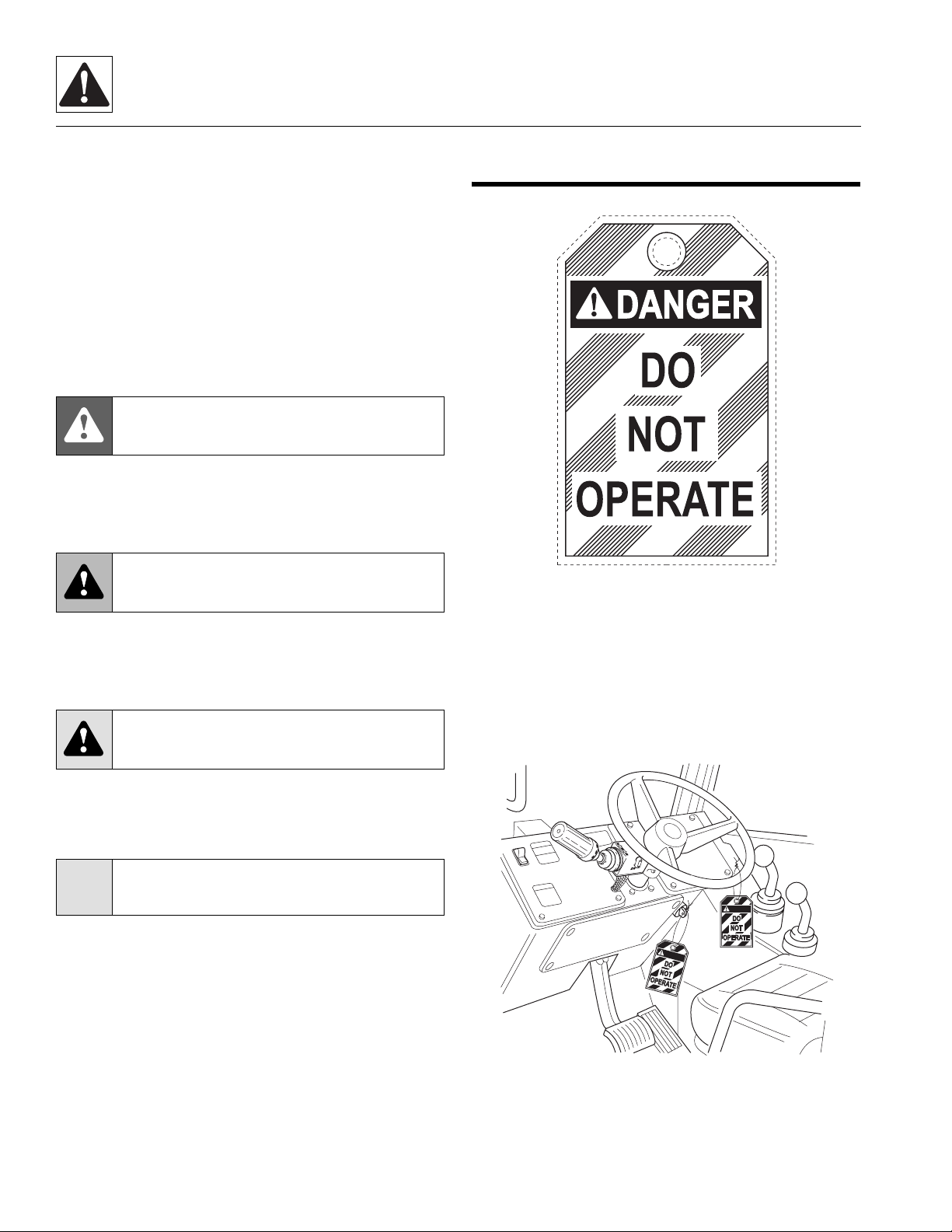
1.5 ACCIDENT PREVENTION TAG
USAGE
MC0690
Figure 1- 2 Accident Prevention Tag
The signal word “WARNING” indicates a potentially
hazardous situation which, if not avoided, could result in
death or serious injury.
CAUTION:
The signal word “CAUTION” indicates a potentially
hazardous situation which, if not avoided, could result in
minor or moderate injury.
CAUTION:
The signal word “CAUTION,” used without the safety
alert symbol, indicates a potentially hazardous situation
which, if not avoided, could result in property damage.
For safe maintenance of the vehicle, read, understand
and follow all DANGER, WARNING and CAUTION
information.
Before beginning any maintenance or service, place an
Accident Prevention Tag (Fig. 1-2) on both the ignition
key switch and the steering wheel (Fig. 1 -3), stating that
the vehicle should not be operated. Actual Accident
Prevention Tags, which can be punched out and used,
are included as the last page in this manual. Retain these
Accident Prevention Tags for reuse at a later date.
DANGER
D
A
N
G
E
R
OH1720
1.4
Figure 1- 3 Place Accident Prevention Tags on Both the
Ignition Key Switch and the Steering Wheel
Model 6036 Legacy

Safety Practices
1.6 SAFETY INSTRUCTIONS
Following are general safety statements to consider
before
Additional statements related to specific tasks and
procedures are located throughout this manual and are
listed prior to any work instructions to provide safety
information before the hazard occurs.
For all safety messages, carefully read, understand and
follow the instructions
1.6.1 Personal Hazards
HAIR and CLOTHING: DO NOT wear loose clothing or
jewelry. Tie up or restrain hair. Wear the correct safety
equipment for the job (including but not limited to: hard
hat; safety shoes; safety glasses, goggles, or face shield;
heavy gloves; hearing protection; reflective clothing; wetweather gear; respirator or filter mask).
EYE PROTECTION: Always wear appropriate eye
protection when chiseling, grinding, sanding, welding,
painting, repairing hydraulic systems, or checking, testing
or charging the battery.
BREATHING PROTECTION: Wear respiratory
protection when grinding or painting.
HEARING PROTECTION: Always wear hearing
protection in a high-noise area.
FOOT PROTECTION: Wear protective footwear with
reinforced toe caps and slip-resistant soles.
LIFTING: NEVER lift a heavy object without the help of at
least one assistant or a suitable sling and hoist.
performing maintenance procedures on a vehicle.
before
proceeding.
1.6.2 Equipment Hazards
OWNERS/OPERATORS MANUAL: Before operating the
vehicle, carefully read, understand and follow the owners/
operators manual.
OPERATIONAL PROTECTION: Before operating the
vehicle or returning it for operational use, check that the
Operator’s Protective Structure is intact, undamaged,
unmodified and secure.
LIFTING OF EQUIPMENT: Before using any lifting
equipment (chains, slings, brackets, hooks, etc.), verify
that it is of the proper capacity, in good working condition
and properly attached.
NEVER stand or otherwise become positioned under a
suspended load or under raised equipment. The load or
equipment could fall or tip.
DO NOT use a hoist or jack to support raised equipment.
A hoist or jack failure can allow the equipment to fall or tip.
Always support equipment with proper capacity blocks or
stands that are properly rated for the load.
COMPRESSED AIR: Before and during the use of
compressed air, wear eye protection and advise other
personnel in the work area that compressed air is about
to be used.
HAND TOOLS: Always use the proper tool for the job;
keep tools clean and in good working order, and use
special service tools only as recommended.
Model 6036 Legacy
1.5
Safety Practices
1.6.3 General Hazards
SOLVENTS: Only use approved solvents, and solvents
that are known to be safe for use.
HOUSEKEEPING: Keep the work area and operator’s
cab clean and remove all hazards (debris, oil, tools, etc.).
FIRST AID: Immediately clean, dress and report all
injuries (cuts, abrasions, burns, etc.), no matter how
minor. Know the location of a first-aid kit, and know how
to use it.
CLEANLINESS: Wear eye protection, and clean all
components with a high-pressure or steam cleaner
before attempting service.
When removing hydraulic components, plug hose ends
and connections to prevent excess leakage and
contamination. Place a suitable catch basin beneath the
vehicle to capture fluid run-off.
1.6.4 Operational Hazards
OPERATIONAL CONSIDERATIONS: Before operating
the vehicle, carefully read, understand and follow the
owners/operators manual.
ENGINE: Stop the engine before performing any service.
DANGEROUS START: Place Accident Prevention Tags
on both the ignition key switch and the steering wheel
before attempting to perform any service or maintenance.
Disconnect battery leads. Place a warning sign on a
vehicle that is dangerous to start, if leaving the vehicle
unattended.
VENTILATION: Avoid prolonged engine operation in
enclosed areas without adequate ventilation.
RADIATOR CAP: Always wear steam-resistant, heatprotective gloves when opening the radiator cap. Cover
cap with a clean, thick cloth and turn slowly to the first
stop to relieve pressure.
SOFT SURFACES AND SLOPES: NEVER work on a
vehicle that is parked on a soft surface or slope (inclined
ground or hill). The vehicle must be on a hard, level
surface with the wheels blocked when performing any
service. Obtain assistance, block all wheels, and add
supports if necessary before beginning any work.
SUPPORTS AND STRAPS: Install safe, stable supports,
slings or straps beneath or around a component or
structural member before beginning any work.
FLUID PRESSURE: Before loosening any hydraulic or
diesel fuel component, hose or tube, turn engine OFF.
Wear heavy, protective gloves and eye protection.
NEVER check for leaks using any part of your body; use
a piece of cardboard or wood instead. If injured, seek
medical attention immediately. Diesel fuel leaking under
pressure can explode. Hydraulic fluid and diesel fuel
leaking under pressure can penetrate the skin, causing
infection, gangrene and other serious personal injury.
Relieve all pressure before disconnecting any
component, part, line or hose. Slowly loosen parts and
allow release of residual pressure before removing any
part or component. Before starting engine or applying
pressure, use components, parts, hoses and pipes that
are in good condition, connected properly and tightened
to the proper torque. Capture fluid in an appropriate
container and dispose of it in accordance with prevailing
environmental regulations.
PRESSURE TESTING: When conducting any test, only
use test equipment that is correctly calibrated and in good
condition. Use the correct equipment in the proper
manner, and make changes or repairs as indicated by the
test procedures to achieve the desired results.
LEAVING VEHICLE: Lower the attachment to the ground
before leaving the vehicle.
TIRE PRESSURE: Always keep tires inflated to the
proper pressure to help prevent dangerous travel and
load-handling situations. DO NOT over-inflate tires.
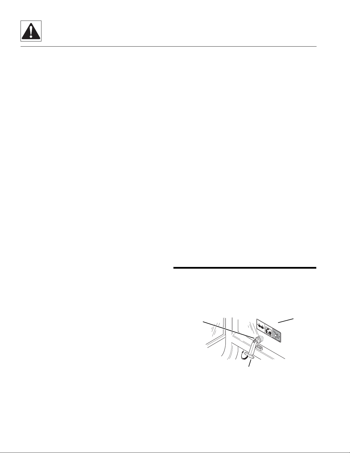
1.7 EMERGENCY EXIT REAR WINDOW
The rear window in the enclosed cab can be used as an
emergency exit by removing the latch pins (Fig. 1 -4, 1)
located on the two window latches (2). Once the latch
pins have been removed, the window (3) can be swung
open.
1
1.
~
2.
3.
791
2
3
09
41
OH1730
1.6
Figure 1- 4 Emergency Exit Rear Window Latch Pins
Model 6036 Legacy
Safety Practices
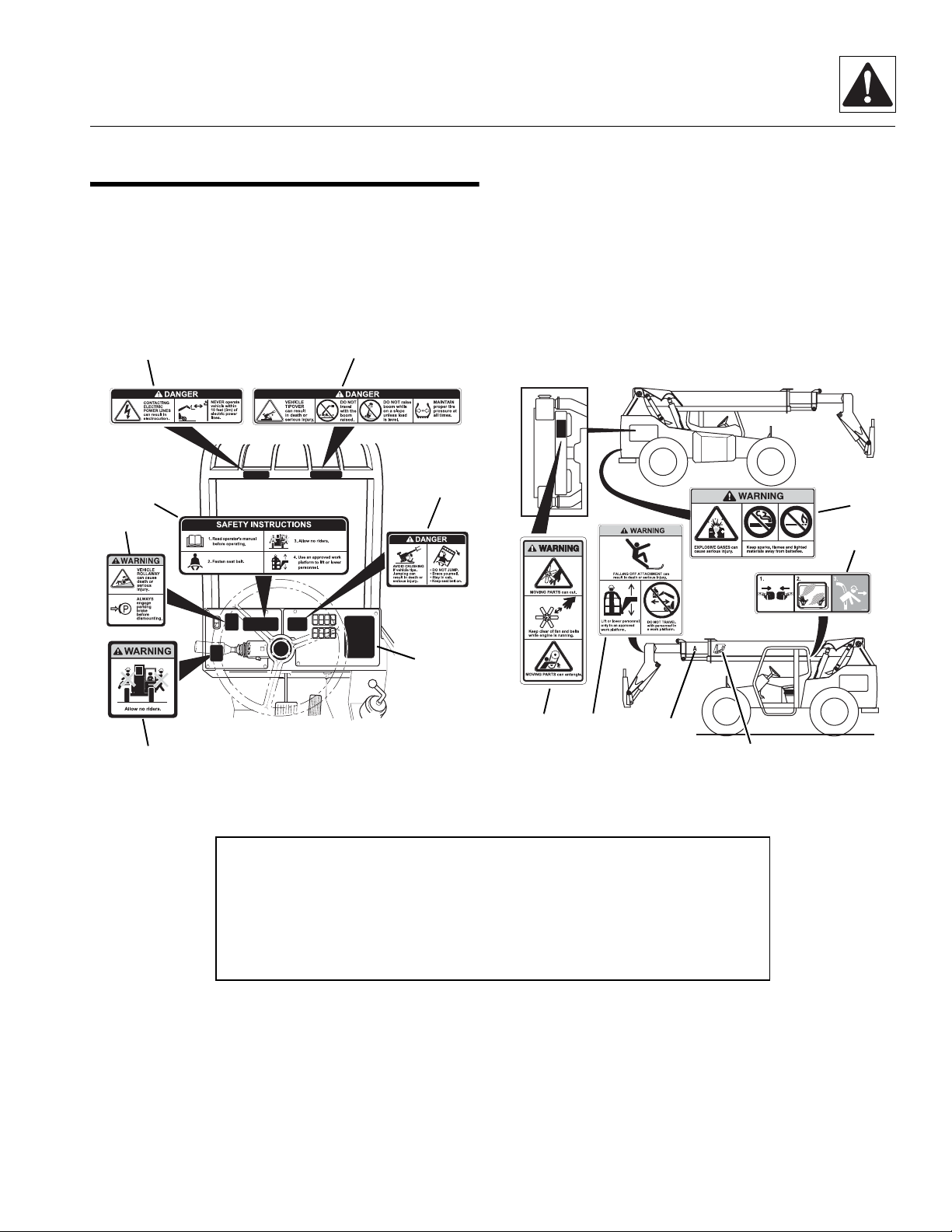
1.8 HAZARD/EMERGENCY
INFORMATION DECALS
Locations of vehicle hazard and other emergency
information decals are shown below. As part of routine
maintenance, check that ALL hazard and emergency
information decals on the vehicle are present and
readable. Keep all decals clean.
4
3
2
5
6
If a replacement decal is needed, refer to the owners/
operators manual and parts catalog for the latest parts
numbers and ordering information, or, contact JLG directly at:
Domestic: 1-877-554-5438
or
International: 1-717-485-5161
12
13
7
OH17412
8
1
1. No Riders WARNING
2. Vehicle Rollaway WARNING
3. Safety Instructions
4. Electrocution DANGER
5. Tipover DANGER - Operating
6. Do Not Jump DANGER
8. Moving Parts WARNING
9. Carrying Personnel WARNING
10. Boom Extend Letters
11. Boom Angle Indicator
12. Explosive Gases WARNING
13. Emergency Exit (Enclosed Cab Only)
9
10
11
OA1652
7. Load Chart Booklet
Note: Many of these hazard related decals are available free of charge by calling
JLG at 1-877-554-5438 (Domestic) or 1-717-485-5161 (International).
Model 6036 Legacy
1.7

Safety Practices
This Page Intentionally Left Blank
1.8
Model 6036 Legacy

Section 2
General Information and Specifications
Contents
PARAGRAPH TITLE PAGE
2.1 6036 Component Terminology . . . . . . . . . . . . . . . . . . . . . . . . . . . . . . . . . . . . . . . . . . 2.3
2.2 Introduction . . . . . . . . . . . . . . . . . . . . . . . . . . . . . . . . . . . . . . . . . . . . . . . . . . . . . . . . .2.4
2.2.1 Service Methods. . . . . . . . . . . . . . . . . . . . . . . . . . . . . . . . . . . . . . . . . . . . . . . . 2.4
2.2.2 The Owners/Operators Manual . . . . . . . . . . . . . . . . . . . . . . . . . . . . . . . . . . . . 2.4
2.2.3 Replacement Parts and Warranty Information . . . . . . . . . . . . . . . . . . . . . . . . . 2.4
2.2.4 Disclaimer. . . . . . . . . . . . . . . . . . . . . . . . . . . . . . . . . . . . . . . . . . . . . . . . . . . . . 2.4
2.3 Torques. . . . . . . . . . . . . . . . . . . . . . . . . . . . . . . . . . . . . . . . . . . . . . . . . . . . . . . . . . . . . 2.5
2.3.1 Fasteners . . . . . . . . . . . . . . . . . . . . . . . . . . . . . . . . . . . . . . . . . . . . . . . . . . . . . 2.5
2.3.2 Bolts and Nuts . . . . . . . . . . . . . . . . . . . . . . . . . . . . . . . . . . . . . . . . . . . . . . . . . 2.5
2.3.3 Straight Thread O-ring Fitting (Non-Adjustable) . . . . . . . . . . . . . . . . . . . . . . . . 2.5
2.3.4 Straight Thread O-ring Fitting (Adjustable) . . . . . . . . . . . . . . . . . . . . . . . . . . . . 2.5
2.3.5 Flat-Face O-ring Fittings . . . . . . . . . . . . . . . . . . . . . . . . . . . . . . . . . . . . . . . . . . 2.6
2.4 Metric Conversion Factors . . . . . . . . . . . . . . . . . . . . . . . . . . . . . . . . . . . . . . . . . . . . . 2.6
2.4.1 Approximate American to Metric Conversions . . . . . . . . . . . . . . . . . . . . . . . . . 2.6
2.4.2 Approximate Metric to American Conversions . . . . . . . . . . . . . . . . . . . . . . . . . 2.7
2.5 Specifications . . . . . . . . . . . . . . . . . . . . . . . . . . . . . . . . . . . . . . . . . . . . . . . . . . . . . . . 2.8
2.5.1 Vehicle Dimensions (With Standard 12-ply 13.00-24 Tires) . . . . . . . . . . . . . . . 2.8
2.5.2 Vehicle Weights . . . . . . . . . . . . . . . . . . . . . . . . . . . . . . . . . . . . . . . . . . . . . . . . 2.10
2.5.3 Attachment Weights . . . . . . . . . . . . . . . . . . . . . . . . . . . . . . . . . . . . . . . . . . . . . 2.11
2.5.4 Performance Specifications . . . . . . . . . . . . . . . . . . . . . . . . . . . . . . . . . . . . . . . 2.11
2.5.5 Hydraulic Cylinder Performance Specifications . . . . . . . . . . . . . . . . . . . . . . . . 2.12
2.5.6 Electrical System . . . . . . . . . . . . . . . . . . . . . . . . . . . . . . . . . . . . . . . . . . . . . . . 2.12
2.5.7 Engine Performance Specifications . . . . . . . . . . . . . . . . . . . . . . . . . . . . . . . . . 2.13
2.5.8 Fluid and Lubricant Capacities . . . . . . . . . . . . . . . . . . . . . . . . . . . . . . . . . . . . . 2.14
2.5.9 Hydraulic System . . . . . . . . . . . . . . . . . . . . . . . . . . . . . . . . . . . . . . . . . . . . . . . 2.15
2.5.10 Tires . . . . . . . . . . . . . . . . . . . . . . . . . . . . . . . . . . . . . . . . . . . . . . . . . . . . . . . . . 2.15
2.5.11 Miscellaneous Specifications . . . . . . . . . . . . . . . . . . . . . . . . . . . . . . . . . . . . . . 2.15
2.5.12 Tamper Proofing . . . . . . . . . . . . . . . . . . . . . . . . . . . . . . . . . . . . . . . . . . . . . . . . 2.16
2.5.13 Fork Ratings . . . . . . . . . . . . . . . . . . . . . . . . . . . . . . . . . . . . . . . . . . . . . . . . . . . 2.16
Model 6036 Legacy
2.1

General Information and Specifications
2.6 Fluids, Lubricants and Capacities . . . . . . . . . . . . . . . . . . . . . . . . . . . . . . . . . . . . . . . 2.16
2.6.1 Axles (Differential Housings) . . . . . . . . . . . . . . . . . . . . . . . . . . . . . . . . . . . . . . 2.16
2.6.2 Axle Wheel Ends . . . . . . . . . . . . . . . . . . . . . . . . . . . . . . . . . . . . . . . . . . . . . . . 2.17
2.6.3 Transmission . . . . . . . . . . . . . . . . . . . . . . . . . . . . . . . . . . . . . . . . . . . . . . . . . . . 2.17
2.6.4 Lubrication Points (Grease Fittings) . . . . . . . . . . . . . . . . . . . . . . . . . . . . . . . . . 2.17
2.6.5 Hydraulic System . . . . . . . . . . . . . . . . . . . . . . . . . . . . . . . . . . . . . . . . . . . . . . . 2.18
2.6.6 Engine. . . . . . . . . . . . . . . . . . . . . . . . . . . . . . . . . . . . . . . . . . . . . . . . . . . . . . . . 2.18
2.6.7 Drive Shaft Splines . . . . . . . . . . . . . . . . . . . . . . . . . . . . . . . . . . . . . . . . . . . . . . 2.19
2.6.8 General Anti-Corrosion . . . . . . . . . . . . . . . . . . . . . . . . . . . . . . . . . . . . . . . . . . . 2.19
2.6.9 Electrical . . . . . . . . . . . . . . . . . . . . . . . . . . . . . . . . . . . . . . . . . . . . . . . . . . . . . . 2.19
2.6.10 Paint . . . . . . . . . . . . . . . . . . . . . . . . . . . . . . . . . . . . . . . . . . . . . . . . . . . . . . . . . 2.20
2.6.11 Thread Locking Compound . . . . . . . . . . . . . . . . . . . . . . . . . . . . . . . . . . . . . . . 2.20
2.7 Cleaning . . . . . . . . . . . . . . . . . . . . . . . . . . . . . . . . . . . . . . . . . . . . . . . . . . . . . . . . . . . . 2.20
2.8 Replacement . . . . . . . . . . . . . . . . . . . . . . . . . . . . . . . . . . . . . . . . . . . . . . . . . . . . . . . . 2.21
2.9 Hoses and Tubes . . . . . . . . . . . . . . . . . . . . . . . . . . . . . . . . . . . . . . . . . . . . . . . . . . . . . 2.21
2.9.1 Hose and Tube Inspection . . . . . . . . . . . . . . . . . . . . . . . . . . . . . . . . . . . . . . . . 2.21
2.9.2 Hose and Tube Installation . . . . . . . . . . . . . . . . . . . . . . . . . . . . . . . . . . . . . . . . 2.21
2.10 Bearings . . . . . . . . . . . . . . . . . . . . . . . . . . . . . . . . . . . . . . . . . . . . . . . . . . . . . . . . . . . . 2.21
2.10.1 Bearing Removal . . . . . . . . . . . . . . . . . . . . . . . . . . . . . . . . . . . . . . . . . . . . . . . 2.21
2.10.2 Bearing Cleaning . . . . . . . . . . . . . . . . . . . . . . . . . . . . . . . . . . . . . . . . . . . . . . . 2.21
2.10.3 Bearing Installation . . . . . . . . . . . . . . . . . . . . . . . . . . . . . . . . . . . . . . . . . . . . . . 2.22
2.11 Pressure Testing and Adjustment . . . . . . . . . . . . . . . . . . . . . . . . . . . . . . . . . . . . . . . 2.22
2.12 After Service Startup and Checks . . . . . . . . . . . . . . . . . . . . . . . . . . . . . . . . . . . . . . . 2.22
2.12.1 After Service Startup . . . . . . . . . . . . . . . . . . . . . . . . . . . . . . . . . . . . . . . . . . . . 2.22
2.12.2 After Electrical/Electronic Component Service . . . . . . . . . . . . . . . . . . . . . . . . . 2.22
2.12.3 After Hydraulic Component Service . . . . . . . . . . . . . . . . . . . . . . . . . . . . . . . . . 2.23
2.12.4 After Brake System Service . . . . . . . . . . . . . . . . . . . . . . . . . . . . . . . . . . . . . . . 2.23
2.12.5 After Fuel System Service . . . . . . . . . . . . . . . . . . . . . . . . . . . . . . . . . . . . . . . . 2.23
2.12.6 After Transmission Service or Replacement . . . . . . . . . . . . . . . . . . . . . . . . . . . 2.23
2.12.7 After Tire and Wheel Service . . . . . . . . . . . . . . . . . . . . . . . . . . . . . . . . . . . . . . 2.24
2.12.8 After Engine Service. . . . . . . . . . . . . . . . . . . . . . . . . . . . . . . . . . . . . . . . . . . . . 2.24
2.12.9 After Boom Service. . . . . . . . . . . . . . . . . . . . . . . . . . . . . . . . . . . . . . . . . . . . . . 2.24
2.12.10 After Axle Service . . . . . . . . . . . . . . . . . . . . . . . . . . . . . . . . . . . . . . . . . . . . . . . 2.24
2.2
Model 6036 Legacy
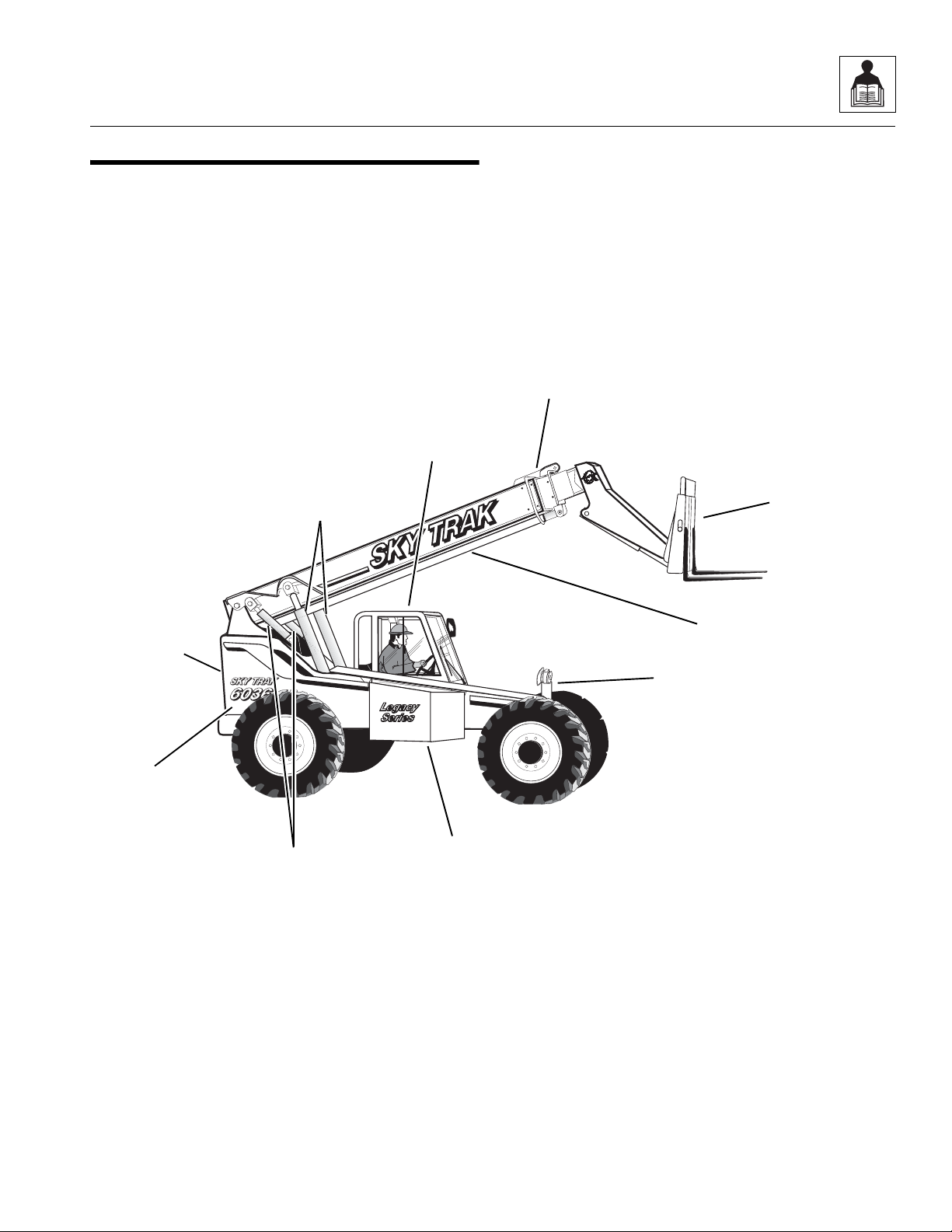
2.1 6036 COMPONENT TERMINOLOGY
To understand the safety, operation and maintenance
information presented in this manual, it is necessary that
the operator/mechanic be familiar with the names and
locations of the major assemblies on this vehicle. The
following illustration identifies the components that are
referred to throughout this manual.
Operator’s
Protective
Structure
General Information and Specifications
Boom
Assembly
Rear Door
(Not Visible)
Engine
Compartment
~
Cylinders (2)
Lift/Lower
Cylinders (2)
Slave
Carriage
Assembly
Extend/Retract
Cylinder
Frame Sway
Cylinder
Hydraulic
Oil Tank
MA8240
Model 6036 Legacy
2.3

General Information and Specifications
2.2 INTRODUCTION
2.2.1 Service Methods
Appropriate service methods and proper repair
procedures are essential for safe, reliable operation of
this vehicle and the safety of the individual doing the
work. This Service Manual provides general direction for
accomplishing service and repair work with tested, effective
techniques. Following them will assure reliability.
There are many variations in procedures, techniques,
tools and parts for servicing vehicles, as well as work
skills. This manual cannot possibly anticipate all such
variations and provide advice or cautions for each one.
Accordingly, anyone who intends to depart from the
instructions in this manual must first consider personal
safety and then vehicle integrity.
IMPORTANT:
environmentally sound waste storage and disposal
practices. NEVER drain fluids on the ground or into a
sewer or catch basin. Use suitable collection containers,
then store and/or dispose of waste products in an
approved and safe manner. Check and obey all Federal,
State and/or Local regulations regarding waste storage,
disposal and recycling.
2.2.2 The Owners/Operators Manual
The Owners/Operators Manual provides information you
need to properly operate and maintain this vehicle.
IMPORTANT: Before you operate this vehicle, read the
manual completely and carefully, so that you will understand
the safety instructions and the operation of the controls
and safety equipment. You must comply with all Danger,
Warning and Caution notices. They are for your benefit.
All references to the right side, left side, front and rear are
given from the operator’s seat looking in a forward direction.
JLG
recommends the use of
The vehicle serial number plate (Fig. 2-1, 1) is located at
the front of the vehicle on the frame sway cylinder upright.
1
OH0280
Figure 2- 1 Vehicle Serial Number Plate Location
IMPORTANT: The replacement of any part on this
vehicle with any other than a
JLG
authorized replacement part can adversely affect the performance, durability, or safety of the vehicle, and will void the warranty.
JLG
disclaims liability for any claims or damages,
whether regarding property damage, personal injury or
death arising out of the use of unauthorized replacement
parts.
A warranty registration form must be filled out by the JLG
Authorized Service Center (ASC), signed by the purchaser and returned to JLG when the vehicle is sold and/or put
into use.
Registration activates the warranty period and helps to
assure that warranty claims are promptly processed. To
guarantee full warranty service, verify that the distributor
has returned the business reply card of the warranty
registration form to JLG.
2.2.3 Replacement Parts and Warranty
Information
For reference when ordering replacement parts or making
service inquiries about the vehicle, the vehicle serial
number is required to help assure the provision of correct
parts and information. Before ordering parts or initiating
service inquiries, make note of the serial number.
2.4
2.2.4 Disclaimer
JLG reserves the right to make changes to and to add improvements upon its product at any time, without public
notice or obligation. JLG also reserves the right to discontinue manufacturing any product at its discretion at any
time.
Model 6036 Legacy
General Information and Specifications
2.3 TORQUES
2.3.1 Fasteners
All fasteners (nuts, bolts, washers, etc.) are equal to SAE
Grade 5 (PC8.8) and are plated, unless otherwise specified.
2.3.2 Bolts and Nuts
Unless otherwise specified, the following values apply for
Grade 5 (PC8.8) nuts and bolts:
Size Torque Size Torque
Inch lb/ft Nm mm Nm lb/ft
1/4 9 12 6,0 10 7
5/16 17 24 8,0 25 18
3/8 31 42 10,0 50 37
7/16 50 68 -- -- --
1/2 75 102 12,0 80 59
9/16 110 150 14,0 130 95
5/8 150 203 16,0 200 146
3/4 250 340 20,0 360 263
7/8 380 515 22,0 510 372
1.0 585 793 24.0 650 475
2.3.3 Straight Thread O-ring Fitting
(Non-Adjustable)
When the vehicle leaves the factory, it is equipped only
with straight thread o-ring fittings. Customer-added
accessories may differ; therefore, consult the
manufacturer’s product literature for information.
1. Verify that both threads and sealing surfaces are
free of burrs, nicks, scratches and any foreign
material.
2. Lubricate the new o-ring with a light coating of
hydraulic oil.
3. Tighten the fitting to the proper torque according to
the following chart:
SAE
Size
4
6
8
10
12
16
20
24
lb/ft Nm
15-17
34-36
58-62
100-110
134-146
202-218
248-272
303-327
Torque
20-23
46-49
79-84
136-149
181-198
274-296
336-369
411-443
2.3.4 Straight Thread O-ring Fitting
(Adjustable)
When the vehicle leaves the factory, it is equipped only
with straight thread o-ring fittings. Customer-added
accessories may differ; therefore, consult the manufacturer’s
product literature for information.
1. Verify that both mating parts are free of burrs, nicks,
scratches and any foreign material.
2. Lubricate the new o-ring with a light coat of hydraulic
oil.
3. Back off the locknut as far as possible.
4. Screw the fitting into the port by hand until the
back-up washer contacts the face of the port and is
pushed all the way towards the locknut.
5. To position the fitting, unscrew by the required
amount, but not more than one full turn.
6. Hold the fitting in the desired position, and tighten to
the proper torque according to the following chart:
Adjustable Straight-Thread O-ring
Fitting Torque Chart
SAE
Size
4
6
8
10
12
16
20
24
lb/ft Nm
15-17
34-36
58-62
100-110
134-146
202-218
248-272
303-327
Torque
20-23
46-49
79-84
136-149
181-198
274-296
336-369
411-443
Model 6036 Legacy
2.5

General Information and Specifications
2.3.5 Flat-Face O-ring Fittings
When the vehicle leaves the factory, it is equipped only
with straight thread o-ring fittings. Customer-added
accessories may differ; therefore, consult the manufacturer’s
product literature for information.
Improper assembly of this type of joint will result in a leaking
joint. Undertightening will result in the joint loosening
during normal use. Foreign material on either sealing
surfaces will cause damage to one or both mating parts
when the joint is tightened, resulting in a leaking joint. The
absence of the fitting o-ring will cause the joint to leak.
1. Verify that both threads and sealing surfaces are
free of burrs, nicks, scratches and any foreign
material.
2. Inspect the male fitting for the presence of the o-ring
seal. Replace the o-ring if missing or damaged.
3. Place the flat surface of the female connector in full
contact with the o-ring in the male connector.
4. Finger-tighten the nut onto the fitting.
5. Hold the fitting in the desired position; for hoses and
swivel fittings, use a second wrench to keep the
female connector from moving during tightening.
Tighten to the proper torque according to the
following chart:
SAE
Size
4
6
8
10
12
16
20
24
lb/ft Nm
19-36
28-54
42-80
65-126
100-180
130-240
150-280
175-330
Torque
26-49
38-73
57-108
88-171
136-244
176-325
203-380
237-447
2.4 METRIC CONVERSION FACTORS
2.4.1 Approximate American to
Metric Conversions
When this is known Multiply by To find
TORQUE
(moment of force)
Pound/feet (lb/ft) 1.356 Newton meters (Nm)
Pound/inches (lb/in) 0.113 Newton meters (Nm)
POWER
Horsepower (hp) 745.7 Watts
SPEED (velocity)
Miles per hour (mph) 1.609 Kilometers per hour
(km/hr; kph)
LENGTH (distance)
Inches (in) 25.4 Millimeters (mm)
Inches (in) 2.5 Centimeters (cm)
Feet (ft) 30.5 Centimeters (cm)
Feet (ft) 0.305 Meters (m)
Yards (yd) 0.9 Meters (m)
Miles (mi) 1.6 Kilometers (km)
AREA
2
Square inches (in
Square feet (ft
Square yards (yd
Square miles (mi
Acres 0.4 Hectares (ha)
MASS (weight)
Ounces (oz) 28.3 Grams (g)
Pounds (lb) 0.4536 Kilograms (kg)
Short tons (2000 lb) 0.9 Metric ton (t)
) 6.5 Square centimeters (cm2)
2
) 0.09 Square meters (m2)
2
) 0.8 Square meters (m2)
2
) 2.6 Square kilometers (km2)
2.6
Model 6036 Legacy

General Information and Specifications
When this is known Multiply by To find
VOLUME
Teaspoons (tsp) 5 Milliliters (ml)
Tablespoons (Tbsp) 15 Milliliters (ml)
3
Cubic inches (in
) 16 Milliliters (ml)
Fluid ounces (fl oz) 30 Milliliters (ml)
Cups (c) 0.24 Liters
Pints (pt) 0.47 Liters
Quarts (qt) 0.95 Liters
Gallons (gal) 3.8 Liters
3
Cubic feet (ft
Cubic yards (yd
) 0.03 Cubic meters (m3)
3
) 0.76 Cubic meters (m3)
AIR PRESSURE
Pounds per
square inch (psi) 6.895 Kilopascals (kPa)
HYDRAULIC PRESSURE
Pounds per
square inch (psi) 0.069 Bar
TEMPERATURE (exact)
To determine degrees Celsius (° C), subtract 32, then
multiply by 0.56; (° F -32) x 0.56 = ° C.
2.4.2 Approximate Metric to
American Conversions
When this is known Multiply by To find
TORQUE
(moment of force)
Newton meters (Nm) 0,738 Pounds/feet (lb/ft)
Newton meters (Nm) 8,85 Pounds/inches (lb/in)
POWER
Watts 0,0013 Horsepower (hp)
SPEED (velocity)
Kilometers per
hour (km/hr; kph) 0,621 Miles per hour (mph)
LENGTH (distance)
Millimeters (mm) 0,0394 Inches (in)
Centimeters (cm) 0,394 Inches (in)
Meters (m) 3,281 Feet (ft)
Meters (m) 1,1 Yards (yd)
Kilometers (km) 0,621 Miles (mi)
When this is known Multiply by To find
AREA
Square centimeters
2
(cm
) 0,4 Square inches (in2)
2
Square meters (m
Square kilometers
2
) 0,6 Square miles (mi2)
(km
Hectares (10000 m
) 1,1 Square yards (yd2)
2
)2,5 Acres
MASS (weight)
Grams (g) 0,035 Ounces (oz)
Kilograms (kg) 2,2 Pounds (lb)
Metric ton
(1000 kg) (t) 1,1 Short tons
VOLUME
Milliliters (ml) 0,03 Fluid ounces (fl oz)
3
Milliliters (ml) 0,06 Cubic inches (in
)
Liters 2,1 Pints (pt)
Liters 1,06 Quarts (qt)
Liters 0,26 Gallons (gal)
3
Cubic meters (m
Cubic meters (m
) 35 Cubic feet (ft3)
3
) 1,3 Cubic yards (yd3)
AIR PRESSURE
Kilopascals (kPa) 0,145 Pounds per square
inch (psi)
HYDRAULIC PRESSURE
Bar 14,5 Pounds per square
inch (psi)
TEMPERATURE (exact)
To determine degrees Fahrenheit (° F), multiply degrees
Celsius (° C) by 1.8, then add 32; (° C x 1.8) + 32 = ° F.
Model 6036 Legacy
2.7

General Information and Specifications
2.5 SPECIFICATIONS
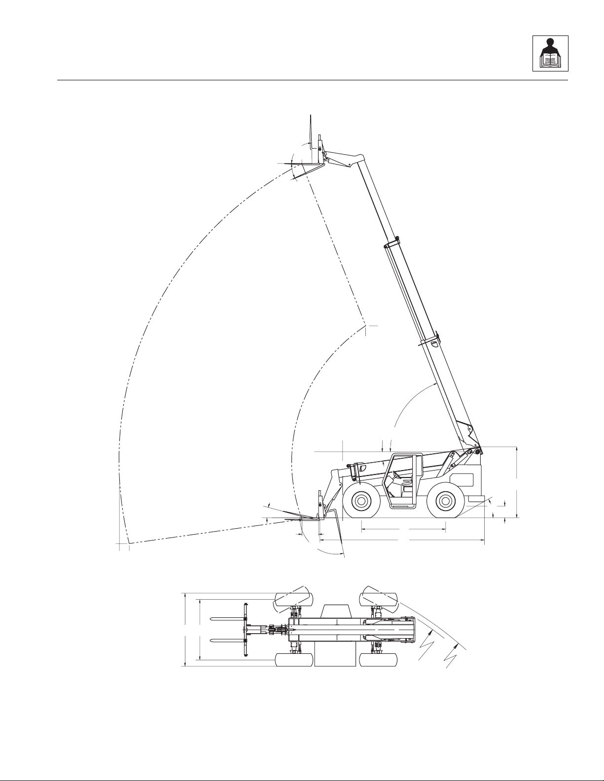
2.5.1 Vehicle Dimensions (With Standard 12-ply 13.00-24 Tires)
Description (Fig. 2- 2)
(A) Length (without Attachment) 217" (5512 mm)
(B) Width 98" (2489 mm)
(C) Height (Boom Lowered) 100" (2540 mm)
(D) Wheelbase 113" (2870 mm)
(E) Tread 84" (2134 mm)
(F) Ground Clearance 16" (406 mm)
(G) Turning Radius, Curb to Curb 165" (4191 mm)
(H) Turning Radius, Clearance 165" (4191 mm)
(I) Maximum Lift Height, Boom Extended 36' 1" (11 m)
(J) Maximum Lift Height, Boom Retracted 20' 2" (6,1 mm)
(K) Maximum Below Grade Depth, Boom Extended 2' 1" (635 mm)
(L) Maximum Reach, from Front of Front Tires 22' 4" (6,8 m)
(M) Maximum Reach at Maximum Lift Angle,
Boom Extended
(N) Maximum Reach at Maximum Lift Angle,
Boom Retracted
(O) Maximum Reach at Minimum Lift Angle,
Boom Extended
(P) Maximum Boom Lift Angle 69°
(Q) Minimum Boom Lift Angle -8°
(R) Angle of Departure 28°
Fork Tilt Angle:
(S) At Minimum Boom Angle - UP 11°
(T) At Minimum Boom Angle - DOWN -101°
(U) At Maximum Boom Angle - UP 87°
(V) At Maximum Boom Angle - DOWN -25°
Frame Tilt Angle (Not Shown):
Right 10.0°
5' 6" (1676 mm)
-15" (-381 mm)
21' 3" (6,5 m)
Left 10.0°
2.8
Model 6036 Legacy
General Information and Specifications
U
M
I
V
J
N
0.0
P
Q
C
S
R
F
K
L
O
T
24.0"
0.0
D
A
BE
H
G
MA8250
Figure 2- 2 Vehicle Dimensions with Standard Tires
Model 6036 Legacy
2.9

General Information and Specifications
2.5.2 Vehicle Weights
Curb Weight (Open Cab) 20,095 lb (9115 kg)
Curb Weight (Enclosed Cab) 20,295 lb (9206 kg)
Operating Load 6,000 lb (2721 kg)
Working Weight (Machine working weight is figured with 72" [1829 mm] carriage, two 48" (1219 mm) pallet forks,
25%-full fuel tank, and standard bias ply tires [no hydrofill]):
Open Cab:
Front Axle 7,767 lb (3523 kg)
Rear Axle 12,328 lb (5592 kg)
Total (Open Cab) 20,095 lb (9115 kg)
Closed Cab:
Front Axle 7,866 lb (3568 kg)
Rear Axle 12,429 lb (5638 kg)
Total (Closed Cab) 20,295 lb (9206 kg)
2.10
Model 6036 Legacy

General Information and Specifications
2.5.3 Attachment Weights
Std 48" Carriage with Shaft 456 lb (205 kg)
Std 60" Carriage with Shaft 526 lb (239 kg)
Std 72" Carriage with Shaft 677 lb (307 kg)
48" Side Tilt Carriage with Shaft and Cylinder 687 lb (312 kg)
60" Side Tilt Carriage with Shaft and Cylinder 752 lb (341 kg)
72" Side Tilt Carriage with Shaft and Cylinder 770 lb (347 kg)
52" Swing Carriage with Shaft and Cylinder 950 lb (428 kg)
72" Swing Carriage with Shaft and Cylinder 1,135 lb (511 kg)
Bucket, 1.125 yd
3
(0,855 m3)
Broom, 8 foot (2,44 m) 1,100 lb (495 kg)
Pallet Forks, 2" x 4" x 48" (5,7 x 10 x 122 cm), quantity: 2278 lb (127 kg)
760 lb (342 kg)
Pallet Forks, 2.25" x 4" x 48" (5,7 x 10 x 122 cm), quan-
312 lb (141 kg)
tity: 2
Block Forks, 2" x 2" x 48" (5 x 5 x 122 cm), quantity: 6 480 lb (216 kg)
Lumber Forks, 1.75" x 7" x 60" (4 x 17,8 152,4 cm),
466 lb (210 kg)
quantity: 2
12 ft Truss Boom 470 lb (213 kg)
Auger Drive Unit 285 lb (128 kg)
Auger Mounting Frame 180 lb (81 kg)
Auger (Various Sizes Available) Varies
Auger Extension (Various Sizes Available) Varies
2.5.4 Performance Specifications
Note: Performance criteria is based on full throttle engine speed unless otherwise specified or not applicable.
Travel Speed (Standard Tires, No Load)
First Gear 0-3.5 mph (0-5,6 km/hr)
Second Gear 0-6 mph (0-9,7 km/hr)
Third Gear 0-14 mph (0-23 km/hr)
Fourth Gear 0-20 mph (0-32 km/hr)
Model 6036 Legacy
2.11

General Information and Specifications
2.5.5 Hydraulic Cylinder Performance Specifications
Note: Vehicle with no load, engine at full throttle, hydraulic oil above 130° F (54° C) minimum, engine at operating
temperature
Boom Extend Less than 15 seconds
Boom Retract Less than 15 seconds
Boom Lift Retracted Less than 15 seconds
Boom Lower Retracted Less than 10 seconds
Attachment Tilt - UP 4-6
Attachment Tilt - DOWN 3.5-5.5
Frame Sway Left to Right 3-6
Frame Sway Right to Left 4-8
.
Function Approximate Times, in Seconds
2.5.6 Electrical System
Battery:
Type, Rating 12 VDC, Negative (-) Ground, Maintenance-Free
Quantity 1
Reserve Capacity 1,000 Cold Cranking Amps @ 0° F (-18° C)
Group/Series C31XH
Alternator 12V, 65 Amps
Fuses - Standard Blade Style:
7.5 Amps Light Switch Relay, Transmission
10 Amps Instrument Panel, Horn/Heater, Steer Select Switch,
Washer/Wipers (Optional)
30 Amps Lights
40 Amps Main
Relays:
Neutral Start Relay 12 Volt
Park Brake Disengage Relay 12 Volt
Headlight Switch Relay 12 Volt
Back-up Relay 12 Volt
Light Switch Relay 12 Volt
2.12
Model 6036 Legacy

General Information and Specifications
2.5.7 Engine Performance Specifications
Note: Engine manufacturer's maximum “high idle” setting is lockwired and sealed. DO NOT disturb this setting.
Engine Make/Model Cummins Turbo/4BT3.9
Displacement
Horsepower 110 HP @ 2,500 rpm
Number of Cylinders 4
Engine High Idle with No Load 2,750 ±100 rpm
Engine Low Idle 1,050 ±50 rpm
Fuel Delivery Fuel Injection
Air Cleaner Dry Type, Replaceable Primary and Safety Elements
Peak Torque 278 lb/ft @ 1,500 rpm (377 Nm @ 1,500 rpm)
Average Fuel Consumption, Depending on Load/Duty 2 gal/hr (1,67 Imp gal/hr, or 7,57 liters/hr)
239 in
3
(3,9 liters)
Model 6036 Legacy
2.13

General Information and Specifications
2.5.8 Fluid and Lubricant Capacities
Engine Crankcase Oil:
Capacity with Filter Change 11.0 qt (10,4 liters)
Filter Capacity 1.0 qt (0,9 liters)
Oil Type SAE 15W40 Diesel Engine Oil
(Refer to Section 2.6.6, “Engine.”)
Fuel Tank:
Total Capacity 37.0 gal (140 liters)
Usable Capacity 35.0 gal (132,5 liters)
Type of Fuel Above 32° F (0° C) Standard No. 2 Diesel. (Refer to Section 2.6.6, “Engine.”)
Type of Fuel Below 32° F (0° C) 50/50 Mix of #1 and #2 Diesel Fuels
(Refer to Section 2.6.6, “Engine.”)
Cooling System:
Capacity w/o Heater
4.0 gal (15 liters)
(including 1.5 qt [1,4 liters] for overflow bottle)
Overflow Bottle Capacity 3.0 qt (2,8 liters)
Type of Fluid 50/50-mix of ethylene glycol and water
(Refer to Section 2.6.6, “Engine.”)
Transmission:
Capacity w/Filter Change 12.5 qt (11,8 liters)
Filter Capacity 1.5 qt (1,4 liters)
Type of Oil Universal Tractor Fluid
(Refer to Section 2.6.3, “Transmission.”)
Axle (Differential Housing):
Capacity 12.2 qt (11,5 liters)
Type of Oil Universal Tractor Fluid. Refer to Section 2.6.1, “Axles
(Differential Housings).”
Axle (Wheel Ends):
Capacity .95 qt (0,9 liters)
Type of Oil Universal Tractor Fluid. Refer to Section 2.6.1, “Axles
(Differential Housings).”
Hydraulic System:
System Capacity 57.5 gal (217,6 liters)
Reservoir Capacity 32.2 gal (122 liters)
Type of Oil ISO Grade 46 Anti-Wear Hydraulic Oil
(Refer to Section 2.6.5, “Hydraulic System.”)
2.14
Model 6036 Legacy

General Information and Specifications
2.5.9 Hydraulic System
Valve Relief Settings (46 GPM Bench Flow):
Main Valve Clipping Relief 3,500 ±100 psi (241,5 bar)
Main Pump Standby Pressure at Pump Outlet 250-300 psi (17-21 bar)
Main Relief Pressure at Unloader Valve "VG" Test Port 2500-3100 psi (172-214 bar)
Parking Brake Relief 650-700 psi (45-48 bar)
Port Relief Boom - Hoist 3,250 ±100 psi (224 ±7 bar)
Port Relief Boom - Extend (Both Sides) 3,250 ±100 psi (224 ±7 bar)
Port Relief Fork Tilt (Both Sides) 3,250 ±100 psi (224 ±7 bar)
Port Relief AUX (Optional) 3,250 ±100 psi (224 ±7 bar)
Parking Brake Pressure Reducing Valve 500-600 psi (34-41 bar)
Steering Pressure Reducing Valve 2,500 ±100 psi (172 ±5 bar)
2.5.10 Tires
Tire Size 13.00-24, 12-ply
Wheel Lug Nut Torque 450 lb/ft (610 Nm)
Air Pressure 55 psi (379 kPa)
Tire Footprint Area (area is established under maximum tip load):
Vehicle with Rated Load
150 in
2
(968 cm2)
Maximum Ground Pressure
(maximum ground pressure at tip = (machine weight + load) / (2 x footprint area):
Vehicle with Rated Load 87 psi (600 kPa)
2.5.11 Miscellaneous Specifications
Steering Wheel:
Maximum Number of Turns, Lock to Lock 3.75 turns
Minimum Number of Turns, Lock to Lock 3.00 turns
Breakout Force:
Utility bucket
(calculated at -24° lip angle, maximum moment)
24,500 lb (11.113 kg)
Model 6036 Legacy
2.15

General Information and Specifications
2.5.12 Tamper Proofing
A tamper-proof means is in place on the following
adjustable components prior to machine shipment. This
can either be tamper-proof paint, or a steel tamper-proof
cap. DO NOT attempt to defeat, bypass or alter any
tamper-proof device.
• Main Valve Port Relief Valves (5) Standard, or (7)
Auxiliary Hydraulics
• Steering Relief Valve (1)
• Attachment Tilt Cylinder Counterbalance Valve (1)
• Lift/Lower Cylinder Counterbalance Valves (2)
• Extend/Retract Cylinder Counterbalance Valve (1)
• Main System Relief Valve (1)
• Parking Brake Relief (1)
2.5.13 Fork Ratings
All approved forks for this vehicle are marked with a
maximum load capacity rating. This rating (Fig. 2-3, 1) is
stamped on the left edge of the fork, just below the fork
pivot shaft. The rating is listed in U.S. pounds and based
upon a 24" (610 mm) load center (2).
This rating specifies the maximum load capacity that the
individual fork can safely carry at a maximum load center
of 24" (610 mm).
Since forks are always used in multiples, the total rating
of any combination of forks is the sum of their rated
capacities.
Other than block forks, use all forks in matched pairs. Use
block forks in matched sets.
2.6 FLUIDS, LUBRICANTS AND
CAPACITIES
2.6.1 Axles (Differential Housings)
a. Axle Lubricants
In general, use a Universal Tractor Fluid that meets the
following specifications:
Nominal viscosity at 104° F (40° C) ...................... 55 cSt
Minimum viscosity at 212° F (100° C).................. 9.1 cSt
Pour point (Maximum).............................. -32° F (-36° C)
Flash point (Minimum).............................392° F (200° C)
Minimum viscosity index ............................................135
Products known to meet these requirements include:
• JOHN DEERE: JDM J20C (HY-GARD)
• FORD/NEW HOLLAND: ESN-M2C134-D
(Hydraulic Oil 134)
• MASSEY-FERGUSON: M-1141
(PERMANTRAN III)
• CHEVRON: CHEVRON 1000 THF
b. Axle Capacities
Axles (differential housings) ...................9.5 qt (9.0 liters)
2.16
1
24 in.
(610mm)
4000 x 24
2
4000 x 24
OS03902
Figure 2- 3 Stamped Fork Rating Location
Model 6036 Legacy

General Information and Specifications
2.6.2 Axle Wheel Ends
a. Axle Wheel-End Lubricants
In general, use a Universal Tractor Fluid that meets the
following specifications:
Nominal viscosity at 104° F (40° C)....................... 55 cSt
Minimum viscosity at 212° F (10° C) .................... 9.1 cSt
Pour point (Maximum).............................. -32° F (-36° C)
Flash point (Minimum)............................ 392° F (200° C)
Minimum viscosity index ............................................ 135
Products known to meet these requirements include:
• JOHN DEERE: JDM J20C (HY-GARD)
• FORD/NEW HOLLAND: ESN-M2C134-D
(Hydraulic Oil 134)
• MASSEY-FERGUSON: M-1141
(PERMANTRAN III)
• CHEVRON: CHEVRON 1000 THF
DO NOT add additional friction modifier to factory-filled
wheel ends. All wheel ends are factory-filled by the
manufacturer with oil. If a wheel end is drained for service, it
should be refilled with the gear oils listed.
Note: DO NOT use synthetic oil without the express
written consent of the manufacturer.
b. Axle Wheel-End Capacity
Wheel ends ......................................... 0.95 qt (0,9 liters)
2.6.3 Transmission
a. Transmission Fluid
In general, use a Universal Tractor Fluid that meets the
following specifications:
Nominal viscosity at 10° F (40° C)......................... 55 cSt
Minimum viscosity at 212° F (100° C) .................. 9.1 cSt
Pour point (Maximum).............................. -32° F (-36° C)
Flash point (Minimum)............................ 392° F (200° C)
Minimum viscosity index ............................................ 135
Products known to meet these requirements include:
• JOHN DEERE: JDM J20C (HY-GARD)
• FORD/NEW HOLLAND: ESN-M2C134-D
(Hydraulic Oil 134)
• MASSEY-FERGUSON: M-1141
(PERMANTRAN III)
• CHEVRON: CHEVRON 1000 THF
b. Transmission Capacity
Capacity w/filter change .....................12.5 qt (11,8 liters)
Filter ....................................................... 1.5 qt (1,4 liters)
2.6.4 Lubrication Points (Grease Fittings)
Lubricants
When lubricating any component via the grease fittings,
use multi-purpose lithium-based grease with EP additives
that meets NLGI Grade 2 specifications. Products known
to meet these requirements include:
• AMOCO AMOLITH EP2
• ARCO LITHOLINE EP2
• BENZ MOLY-SERVICE EP2
• CHEVRON DUROLITH EP2
• CITGO H EP2
• GULF GULFCROWN EP2
• MOBILE MOBILUX EP2
• SHELL ALVANIA EP2
• SUN PRESTIGE 742EP
• TEXACO MULTIFAX EP2
Note: Refer to the appropriate Owners/Operators manual for the maintenance schedule and checklist for
lubrication intervals and grease fitting locations.
Model 6036 Legacy
2.17

General Information and Specifications
2.6.5 Hydraulic System
a. Hydraulic Fluids
The hydraulic system is factory-filled with ISO Grade 46
anti-wear hydraulic oil. When filling the hydraulic system,
use an anti-wear hydraulic oil meeting ISO Grade 46 with
-40° F (-40° C) pour point/ASTM viscosity SUS 215 at
100° F (38° C), or a 10W motor oil that meets the
requirements of U.S. ordinance specification MIL-L-2104C.
Products known to meet these requirements include:
ISO-46 HYDRAULIC OIL
• GULF HARMONY 46 AW
• AMOCO RYKON 46
•MOBIL DTE-25
• ARCO DURO AW S-215
• SHELL TULLUS 46
• BENZ PETRAULIC 46-7C
• SUN SUNVIS 821 WR
• CHEVRON AW HYDRAULIC OIL 46
• TEXACO RANDO HD 46
• CITGO PACEMAKER XD-46
SAE 10W MOTOR OIL
2.6.6 Engine
a. Engine Fluids and Lubricants
1. Engine oil:
Diesel Engine Oil, SAE 15W40
For most climates, use 15W40 motor oil that meets API,
CD or CE (severe duty diesel engine) specifications.
Additives are not necessary. In cold climates where
ambient (outside air) temperatures are consistently below
32° F (0° C), 10W30 motor oil can be used; however,
continuous use of low viscosity oil may cause premature
engine wear.
2. Cooling system (engine coolant):
In general, use a 50/50 mix of premium-quality, ethylene
glycol (commonly referred to as “anti-freeze/anti-boilover”)
and water. Additives are not necessary.
3. Fuel:
In general, use No. 2 diesel fuel. From November 15 to
March 15 when operating in cooler climates where
ambient (outside air) temperatures are consistently at or
below 32° F (0° C), use a 50/50 mix of #1 and #2 diesel
fuels. Use good quality diesel fuel, and change the fuel
filter regularly. Additives are not necessary.
• CASTROL/DEUSOL CRD
• ESSO ESSOLUBE D-3HP
• ESSO ESSOLUBE XD-3
• CASTROL AGRICASTROL HDD
• SHELL RIMULA CT
• SHELL RIMULA X
• SHELL RIMULA TX
Note: For -30° F to +70° F (-34° C to +21° C), 5W20
motor oil with -50° F (-45° C) pour point can be substituted.
However, above 70° F (21° C), hydraulic system oil must
be changed to ISO-46 hydraulic oil or SAE 10W motor
oil.
b. Hydraulic System Capacity
System capacity .............................57.5 gal (217,6 liters)
Reservoir capacity .............................32.2 gal (122 liters)
b. Engine Capacities
1. Engine Oil Capacity
Capacity w/filter change.....................11.0 qt (10,4 liters)
Filter ..........................................................1 qt (0,9 liters)
2. Cooling System Capacity (w/o heater):
Capacity ................................................... 4 gal (15 liters)
Overflow bottle capacity.........................3.0 qt (2,8 liters)
3. Fuel Tank Capacity
Total capacity .......................................37 gal (140 liters)
Usable capacity ................................. 35 gal (132,5 liters)
2.18
Model 6036 Legacy

General Information and Specifications
2.6.7 Drive Shaft Splines
IMPORTANT: DO NOT disassemble any of the drive
shafts (refer to Section 5, “Axles, Drive Shafts, Wheels
and Tires” of this manual for information covering drive
shafts and U-joints). To help ensure optimum performance,
the drive shaft assemblies are specially balanced as a
unit at the factory. When servicing any flange yoke, slip
yoke or drive shaft tube, order a complete assembly.
Refer to the appropriate parts manual for ordering
information.
Respective of the above statement, should it become
necessary to coat the transmission input drive shaft
splines, use molybdenum disulfide grease. Molybdenum
disulfide grease is specifically formulated for this purpose
and is marketed by several manufacturers under various
names, including:
Aldrich Chemical Co., Inc.
Product name:
Catalog Number: 23,484-2
Package Size: 5 g (0.175 oz)
100 g (3.5 oz)
500 g (17.5 oz)
Contact:
Aldrich Chemical Co., Inc.
P.O. Box 335
Milwaukee, WI 53201 USA
Phone: (414) 273-3850
DOW CORNING, INC.
Product name:
Contact:
Dow Corning Corporate Center
P.O. Box 994
Midland, MI 48686-0994 USA
Phone: (517) 496-4400
Aldrich MOLYBDENUM (IV) SULFIDE
MOLYKOTE® 77 Paste
Note: Anti-corrosion protection is especially important in
frame and stabilizer cylinder pin support bores for
protection from fretting corrosion wear.
b. Anti-Corrosion Need Areas
Coat all unplated pins and all bores for cylinder pins,
attachment pivot pins, chain sheave pins, the quick attach
lock pin, and all quick attach lock pin bores. On the boom,
coat the fork shaft and unpainted boom slide pathways.
2.6.9 Electrical
a. Basic Ratings
Battery Rating ....................... 12V DC Negative Ground
Battery Type
Maintenance-Free ..............(1000 Cold Cranking Amps)
Series of Battery .............................................Series 31
Number of Batteries ...........................................One (1)
Alternator Rating ..............................................65 Amps
b. Fuse Ratings
Main ...................................................................40 Amp
Light Switch Relay ............................................7.5 Amp
Instrument Cluster..............................................10 Amp
Horn/Heater .......................................................10 Amp
Steer Select Switch ............................................10 Amp
Optional Washer/Wipers....................................10 Amp
Lights .................................................................30 Amp
Transmission.....................................................7.5 Amp
c. Relay Ratings
2.6.8 General Anti-Corrosion
a. Anti-Corrosion Compound
For general anti-corrosion protection, use a wax film rust
inhibitor that provides a protective film two ten-thousandths
of an inch (0.0002" or 0,00005 mm) thick. One such rust
inhibitor that is specifically formulated for this purpose is
LPS 3
. It is marketed by:
LPS Laboratories, Inc.
4647 Hugh Howell Rd.
Tucker, GA 30085-5052 USA
Phone: 1-800-241-8334
Fax: (770) 493-9206
Model 6036 Legacy
Park Brake Disengage .............................................12V
Headlight Switch ......................................................12V
Light Switch..............................................................12V
Neutral Start .............................................................12V
Back-up ....................................................................12V
2.19

General Information and Specifications
2.6.10 Paint
Unless otherwise specified, paint components as
indicated in the following sections.
a. Orange Paint
Durable, premium Sky Trak orange paint is available in
both a convenient 16-ounce (480 ml) spray can for touchups, and in a production-size, one gallon (3,8 liters)
container for extensive repainting. Consult the appropriate
parts manual for the applicable part number and ordering
information. Use orange paint on all vehicle components
except as specified in paragraphs 2.6.10 B and C.
b. Black Paint
Durable, premium black paint is available in both a
convenient 16-ounce (480 ml) spray can for touch-ups,
and in a production-size, one gallon (3,8 liters) container
for extensive repainting. Consult the appropriate parts
manual for the applicable part number and ordering
information.
• Boom Angle Indicator Pointer
• Brake Pedal
•Radiator
• Seat Adapter Plate
• Radiator Shroud
• Transmission Oil Cooler
•Axles
• Drive Shafts
•Forks
• Mirrors and Mirror Brackets
• Air Cleaner
• Steering Column
c. White Paint
Durable, premium white paint is available in both a
convenient 16-ounce (480 ml) spray can for touch-ups,
and in a production-size, one gallon (3,8 liters) container
for extensive repainting. Consult the appropriate parts
manual for the applicable part number and ordering
information.
• Boom Extend Cylinder
• Wheels
2.6.11 Thread Locking Compound
For general thread locking purposes, Loctite® products,
manufactured by Loctite Corporation, are recommended.
Contact:
Loctite Corporation
1001 Trout Brook Crossing
Rocky Hill, CT 06067 USA
Phone: 1-800-LOCTITE (1-800-562-8483)
FAX: (860) 571-2460
Internet: http://www.loctite.com
®
Loctite
is a registered trademark of Loctite Corporation.
2.7 CLEANING
Dirt and abrasive dust reduce the efficient working life of
parts and systems, and lead to the costly replacement of
components. To help increase the service life of parts,
clean the exterior of all parts before beginning any repairs.
Use cleaning fluids and solvents suitable for cleaning
parts that do not create safety hazards. Certain types of
cleaning fluids can cause skin irritation and damage to
components (such as rubber, electrical parts, etc.).
Servicing the hydraulic system in particular requires
cleanliness of the work area, as well as the components
on the vehicle.
Follow these precautions before attempting to service
any hydraulic component:
1. Flush hose and tube assemblies with a solvent
compatible with hose materials. Blow excess solvent
away with shop air.
2. Plug or cap hydraulic fittings, hoses and tube
assemblies, and protect threads until time of
installation. Clean up any hydraulic fluid spillage
immediately.
3. Flush hydraulic reservoir, fuel tank and gear housing
with a suitable solvent, to remove paint, metal chips,
etc.
4. Protect hydraulic system components from airborne
contaminants. Plug all cylinder, valve, reservoir, tank
and pump openings until time of installation.
5. Use clean, filtered oil when filling the system.
Maintain the hydraulic system at a minimum cleanliness
level of ISO code 18/15-particle ration count.
2.20
Model 6036 Legacy

General Information and Specifications
2.8 REPLACEMENT
ALWAYS use the correct tool when removing or replacing
any part or performing any service.
Some procedures may require the use of specialized
tools. If needed, many of these tools can be obtained
through Snap-on
Contact:
Snap-on Incorporated
P.O. Box 1410
Kenosha, WI 53141-1410 USA
Phone: (262)-656-5200
Internet: http://www.snapon.com
Snap-on
Technologies, Inc.
Replace o-rings, seals and gaskets whenever they are
disturbed. NEVER mix new and old seals or o-rings,
regardless of apparent visual condition. ALWAYS
lubricate new seals and o-rings with hydraulic oil before
installation.
®
is a registered trademark of Snap-on
®
tool distributors.
2.9 HOSES AND TUBES
2.9.1 Hose and Tube Inspection
1. Damaged, dented, crushed, or leaking hose and
tube fittings restrict oil flow and the operation of the
system being served. Fittings showing signs of
movement from their original positions have failed
and must be replaced. ALWAYS replace the entire
hose or tube assembly if the fittings are damaged.
2. Hoses must remain in good condition. Obvious signs
of external hose wear, or hydraulic fluid leaking or
weeping indicate the need to replace the hose
assembly. If in doubt, replace the hose.
3. Replace if any of the following conditions exist:
• Ballooning (replace hose immediately!)
• Kinking, crushing, stretching or deforming
• Concealed corrosion of wire reinforcement
• Chafed outer cover
2.9.2 Hose and Tube Installation
1. When installing a new hose, loosely connect each
end, and verify that the hose takes up the designed
position, and is free of twists and unnecessary
bends before tightening the connection completely.
Tighten any support clamps sufficiently in order to
hold the hose without crushing it, preventing
movement and chafing of the hose.
2. If a hose is replaced on a part that moves, move the
part through its entire range of motion to verify that
the hose will not make contact with any component.
Adjust the hose as necessary.
3. When installing any hose, be sure that the hose
does not become kinked or twisted.
4. NEVER allow free-moving or unsupported hoses to
contact each other or any other component. Such
contact causes chafing and reduces hose life.
2.10 BEARINGS
2.10.1 Bearing Removal
1. NEVER remove bearings unless absolutely
necessary! ALWAYS use the recommended size
and type of bearing puller to reduce the risk of
damage to the bearing or related components.
2. When bearings or bushings are removed, verify that
the bearing or bushing is free of discoloration, nicks,
scuffing, or signs of overheating. If in doubt, replace
the bearing or bushing.
2.10.2 Bearing Cleaning
ALWAYS wear safety glasses. Clean bearings that are
acceptable for service in a suitable solvent. NEVER spin-dry
a bearing with compressed air; this can cause metal-tometal contact and damage the bearing. Compressed air
can also cause a bearing to come apart. After cleaning a
bearing, immerse the bearing in clean lubricating oil until
needed.
Model 6036 Legacy
2.21

General Information and Specifications
2.10.3 Bearing Installation
1. Always install bearings carefully to help avoid
damaging their delicate surfaces.
2. Install bearings using one of the following methods:
• PRESS FIT for installation on rotating parts such
as shafts and gears
• PUSH FIT into static locations such as reduction
gear housings
3. Always install the bearing into the rotating part first,
whenever possible.
4. Use a press or the proper installation tools when
installing a bearing or bushing.
5. In the absence of a press or proper installation tools,
carefully heat the casing and/or bearing in hot oil to
assist in the installation.
2.11 PRESSURE TESTING AND
ADJUSTMENT
Prior to pressure testing or adjustment, verify that all
hoses and tubes are in good condition and that all fittings
are tight.
Use pressure gauges with the proper pressure range and
ratings to measure the specified pressures.
Use correct test procedures to help prevent personal
injury, and damage to the system or test equipment.
Verify that the hydraulic oil is at the proper operating
temperature, 80-120° F (27-49° C), before testing any
pressures or making any adjustments to any valves. If
necessary, operate the vehicle to raise the oil temperature up to the operating temperature. In the absence of a
temperature gauge, the oil temperature can be checked
by placing your hand against the side or the bottom of the
hydraulic oil reservoir. If the tank is too hot to keep the
hand in contact with the tank, the oil temperature should
be within the proper range.
2.12 AFTER SERVICE STARTUP AND
CHECKS
2.12.1 After Service Startup
Note: Refer to the appropriate Owners/Operators man-
ual for engine cold start procedures.
1. Check ALL fluid levels, and add fluids as required.
2. Connect the negative (-) battery cable to the
negative (-) battery terminal if it was disconnected.
3. Start and idle the engine. Check for leaks from the
hydraulic components, engine, radiator, axles,
transmission and brakes. Check for leaks from the
hydraulic oil reservoir plugs or fittings; tighten as
required. Check the levels of all fluids and lubricants.
4. Purge the hydraulic system of air by operating all
vehicle functions through their entire range of
motion. Operate all functions several times to ensure
all air is purged from the system.
5. Check for proper operation of all components.
6. Retract all cylinders fully. Turn the engine OFF, and
check the hydraulic oil level in the hydraulic oil
reservoir. Allow the oil to cool and recheck the level.
Add oil as required to bring the oil level up to the
proper level.
2.12.2 After Electrical/Electronic Component
Service
1. Check the torque of all fasteners securing replaced
electrical/electronic components.
2. Check wire connections to electrical components.
3. Verify that wiring components are dry and free of
moisture.
4. Check connectors for broken, frayed or loose wires.
5. Check wires and wire harnesses for brittle or frayed
wire shielding.
6. Connect the negative (-) battery cable to the
negative (-) battery terminal if it was disconnected.
7. Check the operation of the replaced component(s).
2.22
Model 6036 Legacy

General Information and Specifications
2.12.3 After Hydraulic Component Service
1. Check the torque of fasteners on replaced
components.
2. Check that the hoses and tubes are properly
attached, properly positioned and that all fittings are
properly tightened.
3. If a hydraulic component failed and contaminated
the system:
• Drain the hydraulic oil reservoir
• Flush the system using clean hydraulic oil
• Primp the pump
• Clean the hydraulic oil reservoir
• Change the hydraulic oil filter
4. After normal hydraulic component maintenance,
check the hydraulic oil level, and add oil as required.
5. Start the engine and purge the hydraulic system of
air. Operate all boom functions through their full
range of motion several times. Cycle the hoist and
extend cylinders to purge air from the system.
Visually check for leaks.
6. Check operation of all systems in the hydraulic
circuit by operating the controls through all functions
several times.
2.12.4 After Brake System Service
1. Check the oil level in the axle and replenish with
Universal Tractor Fluid as required.
2. Bleed the air from the brake system.
3. Check the brake pressure.
4. Check the brake operation.
2.12.5 After Fuel System Service
1. Drain and flush fuel tank, if it was contaminated, with
clean fuel.
2. Replace all fuel filters.
3. Fill fuel tank with fresh, clean fuel as required.
4. Bleed the fuel system of air.
2.12.6 After Transmission Service or
Replacement
1. Check transmission oil level and fill to level with
Universal Tractor Fluid as required. (Refer to Section
2.6.3, “Transmission” for information on transmission
lubricants.)
2. Replace transmission filter.
3. Check torque on drive shaft yoke retaining bolts.
Tighten these M12 bolts to 156 lb/ft (212 Nm).
4. Refer to the ZF 4 WG-98 TC Transmission Repair
Manual, JLG P/N 8990455 (ZF P/N 5871 135 002)
for servicing the transmission after overhaul or
repair.
5. Wear suitable eye protection. When an overhauled
or repaired transmission is installed, thoroughly
clean the oil cooler lines to and from the
transmission.
6. Drain and flush the entire system.
7. Disconnect and clean all transmission lines. When
possible, remove transmissions lines from the
vehicle for cleaning.
8. Thoroughly clean transmission filter screens and
cases, and replace transmission filter elements.
CAUTION: DO NOT exceed 165 psi
(11,4 bar) when back flushing the oil cooler.
Applying too much pressure may damage the
oil cooler/radiator.
9. “Back flush” the transmission oil cooler with oil and
compressed air until all foreign material is removed.
Flushing in direction of normal oil flow does not
adequately clean the cooler. If needed, remove the
transmission oil cooler assembly from the vehicle.
DO NOT use flushing compounds for cleaning
purposes.
10. Reassemble all components, and fill the
transmission with clean, fresh Universal Tractor Fluid
through the dipstick tube opening until oil comes up
to the FULL mark on the transmission dipstick.
11. Run engine for two minutes at idle to help prime the
torque converter and transmission lines.
12. Recheck the level of fluid in the transmission with the
engine running at idle.
13. Add Universal Tractor Fluid as necessary to bring
the fluid level up to the FULL mark on the
transmission dipstick. Install the oil dipstick. Recheck
the oil level when it reaches operating temperature
(180-200° F or 83-94° C).
14. Recheck all drain plugs, lines, connections, etc., for
leaks, and tighten where necessary.
Model 6036 Legacy
2.23

General Information and Specifications
2.12.7 After Tire and Wheel Service
1. Check air pressure.
2. Check wheel nut torque. Tighten to 450 lb/ft
(610 Nm).
2.12.8 After Engine Service
Consult the qualified service agent (manufacturer’s
representative and/or service manual) for proper
procedures before engine startup.
2.12.9 After Boom Service
1. Check wear pads.
2. Check chain tension adjustment.
3. Apply grease at all lubrication points (grease fittings).
(Refer to the appropriate Owners/Operators manual.)
4. Check for proper operation by operating all boom
functions through their full range of motion several
times.
2.12.10 After Axle Service
1. Check fluid levels.
2. Check torque on drive shaft flange yoke retaining
bolts. Tighten these M12 bolts to 156 lb/ft (212 Nm).
3. Check wheel nut torque. Tighten to 450 lb/ft (610 Nm).
4. Check toe-in if required.
5. Apply grease at all lubrication points (grease fittings).
6. Refer to the axle manufacturer’s maintenance
manual for further information.
2.24
Model 6036 Legacy

Section 3
Boom
Contents
PARAGRAPH TITLE PAGE
3.1 Boom System Component Terminology. . . . . . . . . . . . . . . . . . . . . . . . . . . . . . . . 3.2
3.2 Boom System . . . . . . . . . . . . . . . . . . . . . . . . . . . . . . . . . . . . . . . . . . . . . . . . . . . . . 3.3
3.2.1 Boom System Description. . . . . . . . . . . . . . . . . . . . . . . . . . . . . . . . . . . . . 3.3
3.2.2 Boom System Operation . . . . . . . . . . . . . . . . . . . . . . . . . . . . . . . . . . . . . . 3.3
3.3 Boom Assembly Maintenance . . . . . . . . . . . . . . . . . . . . . . . . . . . . . . . . . . . . . . . . 3.3
3.3.1 Inner Boom Removal . . . . . . . . . . . . . . . . . . . . . . . . . . . . . . . . . . . . . . . . 3.3
3.3.2 Intermediate Boom Removal. . . . . . . . . . . . . . . . . . . . . . . . . . . . . . . . . . . 3.9
3.3.3 Outer Boom Removal . . . . . . . . . . . . . . . . . . . . . . . . . . . . . . . . . . . . . . . . 3.14
3.3.4 Outer Boom Installation. . . . . . . . . . . . . . . . . . . . . . . . . . . . . . . . . . . . . . . 3.20
3.3.5 Intermediate Boom Installation . . . . . . . . . . . . . . . . . . . . . . . . . . . . . . . . . 3.28
3.3.6 Inner Boom Installation . . . . . . . . . . . . . . . . . . . . . . . . . . . . . . . . . . . . . . . 3.33
3.3.7 Boom Chains. . . . . . . . . . . . . . . . . . . . . . . . . . . . . . . . . . . . . . . . . . . . . . . 3.44
3.3.8 Boom Wear Pads . . . . . . . . . . . . . . . . . . . . . . . . . . . . . . . . . . . . . . . . . . . 3.56
3.4 Quick Attach Assembly . . . . . . . . . . . . . . . . . . . . . . . . . . . . . . . . . . . . . . . . . . . . . 3.59
3.4.1 Disconnecting from an Attachment . . . . . . . . . . . . . . . . . . . . . . . . . . . . . . 3.59
3.4.2 Connecting to an Attachment . . . . . . . . . . . . . . . . . . . . . . . . . . . . . . . . . . 3.59
3.4.3 Quick Attach Removal. . . . . . . . . . . . . . . . . . . . . . . . . . . . . . . . . . . . . . . . 3.60
3.4.4 Quick Attach Installation . . . . . . . . . . . . . . . . . . . . . . . . . . . . . . . . . . . . . . 3.60
3.5 Troubleshooting . . . . . . . . . . . . . . . . . . . . . . . . . . . . . . . . . . . . . . . . . . . . . . . . . . . 3.61
Model 6036 Legacy
3.1

Boom
3.1 BOOM SYSTEM COMPONENT
TERMINOLOGY
To understand the safety, operation and maintenance
information presented in this section, it is necessary that
the operator/mechanic be familiar with the names and
locations of the major assemblies of the boom system.
The following illustration identifies the components that
are referred to throughout this section.
Inner Boom Section
with Gooseneck
Extend Chains
Intermediate
Boom Section
Outer
Boom
Section
Quick Attach
FRONT
Attachment
Tilt Cylinder
Boom Extend/
Retract Cylinder
Retract Chain
MA6390
3.2
Model 6036 Legacy
Boom
WARNING: DO NOT service the vehicle
without following all safety precautions as
outlined in the “Safety Practices” section of this
manual. Failure to follow the safety practices
may result in death or serious injury.
3.2 BOOM SYSTEM
3.2.1 Boom System Description
The boom operates via an interchange among the
hydraulic and mechanical systems. Components
involved include the joystick, attachment tilt cylinder,
extend/retract cylinder, lift/lower cylinders, slave
cylinders, extend and retract chains, various pivots,
supporting hardware and other components.
3.2.2 Boom System Operation
The boom assembly consists of inner, intermediate and
outer booms. Boom extension and retraction is
accomplished via hydraulic power and chain movement.
As the extend/retract hydraulic cylinder, which is anchored
at the front of the intermediate boom and the rear of the
outer boom, begins to extend, it forces the intermediate
boom out of the outer boom.
The inner and outer booms are connected by extend and
retract chains. These chains are routed around sheaves
on the intermediate boom. As the intermediate boom is
forced out, the extend chain pulls the inner boom out of
the intermediate boom.
As hydraulic pressure is applied to the retract port on the
extend/retract cylinder, the intermediate boom is pulled
back into the outer boom, and the retract chain pulls the
inner boom back into the intermediate boom.
This mechanical linkage formed by the chains and
supporting hardware, extends and retracts the intermediate
and inner booms at the same rate.
The outer boom does not extend or retract, but lifts and
lowers via action of the lift/lower cylinders.
3.3 BOOM ASSEMBLY MAINTENANCE
The boom assembly consists of the inner, intermediate
and outer booms and supporting hardware.
IMPORTANT: Boom replacement must be completed in
sequence, one boom section at a time, as described in
these instructions. Replacement of two or more boom
sections as a unit requires special considerations that
are not covered in these instructions.
The inner, intermediate and outer boom removal
instructions must be completed in sequence. The inner
boom must be removed before removing the intermediate
boom. The inner boom and intermediate boom must be
removed one at a time before removing the outer boom.
Before beginning, conduct a visual inspection of the
vehicle, work area and task about to be undertaken.
Read, understand and follow these instructions.
After servicing the boom, perform the following:
1. Check wear pads. (Refer to Model 6036 Legacy
Owners/Operators Manual.)
2. Check chain wear and tension adjustment. (Refer to
Section 3.3.7, a. “Boom Chain Inspection” and
Section 3.3.7, c. “Boom Chain Tension Check.”)
3. Apply grease at all lubrication points (grease fittings).
(Refer to Model 6036 Legacy Owners/Operators
Manual.)
4. Check for proper operation by operating all boom
functions through their full range of motion several
times.
3.3.1 Inner Boom Removal
WARNING: Wear protective footwear
with reinforced toe caps and slip-resistant
soles. Failure to comply can result in foot or
other bodily injury from crushing, slipping or
falling.
WARNING: NEVER lift a heavy object
without the help of at least one assistant or a
suitable sling and hoist. Failure to comply can
result in death or serious personal injury.
Model 6036 Legacy
1. Remove any attachment from the quick attach
assembly. (Refer to
from an Attachment.”)
Section 3.4.1, “Disconnecting
3.3

Boom
Note: This procedure will require a clear space of
approximately 16 feet at the front and rear of the vehicle.
2. Park the vehicle on a hard, level surface. Move the
boom to a horizontal (level) position. Extend (or retract)
the boom until the boom is extended approximately
two feet (610 mm). Move the quick attach to the
horizontal position. Place the travel select lever in
the (N) NEUTRAL position, place the neutral lock
lever in the (N) NEUTRAL LOCK position, engage
the parking brake and shut the engine OFF.
3. Remove one thumbscrew (Fig. 3 -1, 1), one internaltooth lockwasher (2) and one flat washer (3) holding
the rear cover (4) to the rear of the outer boom (5).
Lift the rear cover straight up until the capscrew in
the top of the cover clears the hole in the top of the
outer boom. Remove the cover from the outer boom.
.
5
4
1
MA6620
Figure 3- 2 Loosen the Extend Chains
5. At the front of the intermediate boom (Fig. 3 -3, 1),
remove the capscrews (2) and lockwashers (3)
holding the top wear pads (4) and spacers (5) to the
inside of the intermediate boom. Label the wear
pads and spacers as “Top Left” and “Top Right”
sides. Save the spacers, capscrews, lockwashers
and wear pad inserts (6).
3
2
1
Figure 3-1 Remove the Boom Rear Cover
4. At the rear of the boom, measure the amount of
threads protruding beyond each elastic locknut
(Fig. 3-2, 1), and record that measurement for
reassembly. Loosen the extend chains by loosening
the two locknuts located at the rear of the inner
boom. The locknuts must remain fully engaged with
the threads of the extend chain clevis’.
MA6420
2
3
3
1
5
4
6
Figure 3- 3 Remove the Intermediate Boom
Front Top Wear Pads
MA7790
3.4
Model 6036 Legacy

6. At the front of the intermediate boom (Fig. 3-4, 1),
remove the capscrews (2), lockwashers (3) and flat
washers (4) holding the side wear pads (5) and
shims (6) to the inside of the intermediate boom.
Label the wear pads and shims as “Left Top/Bottom”
and “Right Top/Bottom.” Save the shims, capscrews,
flat washers, lockwashers and wear pad inserts (7).
Boom
WARNING: Hydraulic fluid leaking under
pressure can penetrate the skin, cause infection,
gangrene, and death or serious personal
injury. If injured, see a doctor immediately.
Relieve all pressure before disconnecting any
component, part, line or hose. Slowly loosen
parts and allow release of residual pressure
before removing any parts or component.
WARNING: Wait for the hydraulic fluid
to cool before servicing any hydraulic component.
Hot hydraulic oil can cause severe burns.
7
Figure 3- 4 Remove Intermediate Boom Front Left
7. Return to the cab, fasten your seat belt and start the
engine. Retract the boom slightly until slack is
noticed in the extend chains. Shut the engine OFF.
8. Move the attachment tilt joystick in both directions to
relieve any trapped pressure in the attachment tilt
system. If your vehicle is equipped with optional
auxiliary hydraulics, move the auxiliary hydraulic
joystick in both directions to relieve any trapped
pressure in the auxiliary hydraulics system.
9. Place an Accident Prevention Tag on both the
ignition key switch and the steering wheel, stating
that the vehicle should not be operated. (Refer to
Section 1.5, “Accident Prevention Tag Usage.”)
10. Disconnect the battery negative (-) ground cable at
the battery negative (-) terminal to prevent the
engine from starting accidentally.
11. Locate the two hoses (Fig. 3- 5, 1) attached to the
base of the attachment tilt cylinder (2) inside the
gooseneck (3).
5
6
and Right Side Wear Pads
~
1
2
4
3
MA7800
12. Label and disconnect the hoses (Fig. 3-5, 1) from
the fittings (4) on the attachment tilt cylinder. Plug
the hose ends and cap the fittings on the attachment
tilt cylinder to prevent dirt and debris from entering
the hydraulic system and/or cylinder.
3
1
4
2
MA6400
Figure 3- 5 Disconnect the Attachment
Tilt Cylinder Hoses
Model 6036 Legacy
3.5

Boom
13. If your vehicle is equipped with optional auxiliary
hydraulics, label and remove the two hoses (Fig. 3-6, 1)
from the bulkhead fittings (2) inside the gooseneck (3).
Plug the hose ends, and cap the bulkhead fittings to
prevent dirt and debris from entering the hydraulic
system.
If you are replacing the inner boom with a new inner
boom, remove the female coupler, male nipple and
bulkhead fittings from the bulkhead plate inside the
gooseneck.
3
1
2
14. Without optional auxiliary hydraulics: Inside the
inner boom, remove the two capscrews (Fig. 3-7, 1),
two lockwashers (2) and two flat washers (3) holding
the clamp cover (4) and stack clamps (5) to the floor
of the inner boom. Remove the clamp cover plate
and all of the clamps. Proceed to Step 16.
1
2
4
3
5
2
MA6410
Figure 3- 6 Disconnect the Auxiliary Hydraulics Hoses
MA6510
Figure 3- 7 Remove the Attachment Tilt Hose Clamps
from the Inner Boom
3.6
Model 6036 Legacy

15. With optional auxiliary hydraulics: Inside the inner
boom, remove the two capscrews (Fig. 3 -8, 1), two
lockwashers (2) and two flat washers (3) holding the
clamp cover (4) and stack clamps (5) to the floor of the
inner boom. Remove the clamps from the inner boom.
1
2
4
3
Boom
3
5
Figure 3- 8 Remove the Attachment Tilt and Auxiliary
Hydraulics Hose Clamps from the Inner Boom
16. Pull the free ends of the attachment tilt hoses
(Fig. 3-9, 1) and (optional) auxiliary hydraulic hoses
(2) from inside the inner boom, and out the rear of
the boom (3). Allow the hoses to hang from the rear
of the boom.
MA6600
2
1
2
Figure 3- 9 Pull the Attachment Tilt and Auxiliary
Hydraulics Hoses from the Inner Boom
MA6610
Note: Record the location of the shoulder bolt
(Fig. 3-10, 2) to ensure correct installation.
17. At the rear of the outer boom, locate the end of the
retract chain (Fig. 3 -10, 1). Remove the elastic
locknut (2) and shoulder bolt (3) holding the retract
chain clevis (4) to the anchor plates (5). Save the
shoulder bolt. Discard the locknut. Remove the
retract chain from the anchor plates. Allow the retract
chain (1) to hang out the rear of the boom.
3
1
Model 6036 Legacy
5
4
Figure 3- 10 Remove the Retract Chain Anchor Plates
from the Retract Chain
2
MH2340
3.7

Boom
18. Remove the elastic locknut (Fig. 3 -11, 1) and
shoulder bolt (2) holding the two yoke plates (3) to
disconnect the extend chain yoke (4) from the outer
boom. Retain the shoulder bolt and discard the
elastic locknut. Lay the chain assembly flat against
the inner boom.
19. Inspect the yoke plates for wear or distortion. If any
wear or distortion is detected, both plates must be
replaced. If no wear is detected, the plates can
remain assembled to the extend chain clevis’.
1
3
2
4
3
1
MA7810
Figure 3- 11 Disconnect the Extend Chain
Note: If replacing the inner boom assembly with a new
inner boom, the quick attach assembly and the
attachment tilt cylinder should be removed at this time. If
the inner boom is not to be replaced, the quick attach
assembly and attachment tilt cylinder can remain in place.
20. Remove the quick attach assembly. (Refer to Section
3.4.3, “Quick Attach Removal.”)
Note: The attachment tilt cylinder is heavy. Use a hoist
and sling to support the attachment tilt cylinder when the
base end pin is removed.
21. Remove the retaining ring (Fig. 3- 12, 1) from one
side of the base end pivot pin (2). Save the retaining
ring. Use a brass punch and rawhide hammer to
remove the base end pivot pin from the inner boom
gooseneck (3).
22. Inspect the pin for nicks or surface corrosion. Use
fine emery cloth to fix minor nicks or corrosion. If
damaged and not repairable, the pin must be
replaced.
23. Lower the attachment tilt cylinder (Fig. 3-12, 4) with
the hoist, and remove it from the rear of the
gooseneck. Place the attachment tilt cylinder on a
clean, level surface until installation.
2
4
MA6450
Figure 3- 12 Remove Attachment Tilt Cylinder
Note: Use a hoist capable of lifting 5000 lbs (2268 kg)
and two slings to remove the inner boom.
24. Place the slings around the inner boom. Pull the
inner boom straight out of the intermediate boom.
25. Reposition the sling at the approximate center of the
inner boom, and then continue withdrawing the boom
until it clears the vehicle.
26. Carefully lower the inner boom onto suitable
supports to prevent it from tipping over.
WARNING: NEVER weld or drill the
boom. The structural integrity of the boom will
be impaired if subjected to any repair involving
welding or drilling. Failure to comply can result
in death or serious personal injury.
27. Inspect the boom and welds. Contact the JLG
Service Department or the local JLG Authorized
Service Center (ASC) if structural damage is
detected.
28. Inspect hoses, hardware, wear pads, mounting
points, chains and other components visible with the
inner boom removed. Replace if damaged.
29. At the rear of the inner boom (Fig. 3-13, 1), remove
the capscrews (2), lockwashers (3) and flat washers
(4) holding the top wear pads (5), spacers (6) and
shims (7) to the top of the inner boom. Label the
wear pads, spacers and shims as “Top Left” and
“Top Right” sides. Save the spacers, shims,
capscrews, lockwashers and wear pad inserts (8).
3.8
Model 6036 Legacy

Boom
30. Remove the capscrews (Fig. 3 -13, 9), lockwashers
(10) and flat washers (11) holding the side wear
pads (12) and shims (13) to the sides of the inner
boom. Label the wear pads and shims as “Left Top/
Bottom” and “Right Top/Bottom.” Save the shims,
capscrews, lockwashers, flat washers and wear pad
inserts (14).
31. Remove the capscrews (Fig. 3-13, 15), lockwashers
(16) and flat washers (17) holding the bottom wear
pad (18) and spacer (19) to the bottom of the inner
boom. Label the wear pad and spacer as “Bottom.”
Save the spacer, capscrews, lockwashers and wear
pad inserts (20).
8
5
6
7
4
3
2
1
15
16
17
9
10
11
3.3.2 Intermediate Boom Removal
WARNING: Wear protective footwear
with reinforced toe caps and slip-resistant soles.
Failure to comply can result in foot or other
bodily injury from crushing, slipping or falling.
WARNING: NEVER lift a heavy object
without the help of at least one assistant or a
suitable sling and hoist. Failure to comply can
result in death or serious personal injury.
1. Remove the inner boom as described in Section
3.3.1, “Inner Boom Removal.”
2. At the front of the outer boom (Fig. 3-15, 1), remove
the capscrews (2), lockwashers (3) and flat washers (4)
holding the top wear pads (5) to the inside of the outer
boom. Label the wear pads as “Top Left” and “Top
Right” sides. Save the capscrews, lockwashers, flat
washers and wear pad inserts (6).
1
2
3
4
13
19
18
20
Figure 3- 13 Remove Inner Boom Wear Pads
32. Inspect all wear pads (Fig. 3- 14, 1) for wear. If the
angle indicators (2) on the ends of the wear pads are
visible, the wear pads can be reused. If the pads
show uneven wear (front to back), they should be
replaced. Replace pads as a set if worn or damaged.
2
1
14
MA6900
2
MA2070
12
5
6
MA7390
Figure 3- 15 Remove the Outer Boom
Front Top Wear Pads
Figure 3- 14 Wear Pad Wear Indicators
Model 6036 Legacy
3.9

Boom
3. At the front of the outer boom (Fig. 3-16, 1), remove
the capscrews (2), lockwashers (3) and flat washers
(4) holding the side wear pads (5) and shims (6) to
the inside of the outer boom. Label the wear pads as
“Left Top/Bottom” and “Right Top/Bottom.” Save the
capscrews, lockwashers, flat washers, shims and
wear pad inserts (7).
4
3
2
7
5
6
4
3
1
3
4
3
2
4
1
MA7410
7
1
5
6
Figure 3- 16 Remove the Outer Boom Left and
Right Side Wear Pads
MA7400
4. If replacing the intermediate boom with a new boom
section, remove the lower wear pads at the front of
the boom. Remove two 3/8-16 x 1-3/4" capscrews
(Fig. 3-17, 1) and one 3/8-16 x 1" capscrew (2),
three lockwashers (3) and three flat washers (4)
securing each lower wear pad (5) and spacers (6) to
the inside of the boom. Label the wear pads and
spacers as “Left” or “Right” sides. Save the capscrews,
lockwashers, spacers and wear pad inserts (7).
Figure 3- 17 Remove the Intermediate Boom Lower,
Front Wear Pads
5. At the rear of the boom, remove two capscrews
(Fig. 3-18, 1), two lockwashers (2) and two flat washers
(3) holding the hose reel assembly (4), lower wear pad
(5) and spacer (6) to the lower plate on the intermediate
boom. Reassemble the capscrews, lockwashers and
flat washers to hold the lower wear pad in place for
intermediate boom removal.
1
2
3
4
3.10
5
6
MA6630
Figure 3- 18 Remove the Hose Reel Assembly from the
Rear of the Intermediate Boom
Model 6036 Legacy

Boom
6. Remove the capscrews (Fig. 3 -19, 1), lockwashers
(2) and flat washers (3) holding the hose reel side
plate (4), lower left side wear pad (5) and shims (6)
to the side of the intermediate boom. Save the
capscrews, lockwashers, flat washers, shims and
wear pad inserts (7).
7
5
6
4
3
2
1
b. After the hoses are removed from behind the
lower retaining bolt (Fig. 3 -20, 4), insert the
shoulder bolt through the plates, inserting the
spacers between the plates as the bolt is
inserted. Loosely reassemble the 3/8" flat
washer (3) and 3/8-16 elastic locknut (2) to hold
the shoulder bolt in place. DO NOT fully tighten
at this time.
c. Remove the 1/2-13 elastic locknut (Fig. 3-20, 6)
from the upper retaining capscrew (7). While
pulling the capscrew out, catch the spacers (8)
from between the plates as the capscrew is
removed. Pull the capscrew out far enough to
remove the hoses from the hose reel.
d. After the hoses are removed, insert the capscrew
(Fig. 3-20, 7) through the plates, inserting the
spacers (8) between the plates as the capscrew
is inserted. Reassemble the 1/2-13 elastic
locknut (6) to hold the capscrew in place.
8
7
MA6640
Figure 3- 19 Remove the Intermediate Boom
Hose Reel Side Plate
7. Remove the hose reel assembly, with hoses, from
the rear of the boom. Allow the hose reel assembly
to slide down the hoses, out of the boom and allow it
to rest on the floor.
8. Label and remove the hoses from the hose reel
assembly. The center bolt (Fig. 3-20, 1) can remain
in place to hold the hose reel and side plates
together.
a. Remove the 3/8-16 elastic locknut (Fig. 3- 20, 2)
and 3/8" flat washer (3) from the lower retaining
shoulder bolt (4). While pulling the shoulder bolt
out, catch the spacers (5) from between the
plates as the bolt is removed. Pull the bolt out far
enough to remove the hoses from the hose reel.
2
3
1
4
5
Figure 3- 20 Remove the Hoses from the
Hose Reel Assembly
6
MA6560
Model 6036 Legacy
3.11

Boom
9. Without optional auxiliary hydraulics: At the front
of the outer boom, label and remove the attachment
tilt hoses (Fig. 3 -21, 1 and 2) from the tube
assemblies (3 and 4). Cap the hose ends.
10. With optional auxiliary hydraulics: Label and
remove the auxiliary hoses (Fig. 3-21, 5 and 6) from
the tube assemblies (7 and 8). Cap the hose ends.
4
3
1
2
6
3
5
3
7
4
8
7
8
Figure 3- 21 Disconnect the Attachment Tilt and
Auxiliary Hydraulics Hoses
4
MA7420
2
1
MA6740
Figure 3 -22 Remove the Retract Chain Sheave
16. Support the front of the extend/retract cylinder
(Fig. 3-23, 1).
17. Remove the retaining ring (Fig. 3- 23, 2) from one
side of the extend/retract cylinder rod end mounting
pin (3). Use a brass punch and a rawhide hammer to
remove the rod end pin from the mounting ears (4)
on the intermediate boom. Save the retaining ring.
18. Inspect the pin (Fig. 3- 23, 3) for wear or damage.
Use fine emery cloth to fix minor nicks or corrosion.
If the pin is damaged, replace the pin. Save the
retaining ring.
11. Pull the hoses out from between the intermediate
boom and the outer boom and out the rear of the
boom.
12. At the rear of the boom, remove the capscrew
(Fig. 3-22, 1) and lockwasher (2) holding the retract
chain sheave pin (3) to the mounting plate inside the
intermediate boom.
13. Remove the retract chain sheave pin (Fig. 3 -22, 3)
from the mount and the retract chain sheave (4).
Remove the retract chain sheave from the
intermediate boom.
14. Inspect the bushings inside the sheave (Fig. 3-22, 4).
Replace the bushings if there are any signs of wear.
15. Inspect the pin (Fig. 3-22, 3) for wear or damage.
Replace the pin if showing signs of wear.
3.12
2
4
1
Figure 3- 23 Remove the Extend/Retract
4
Cylinder Rod End Pin
3
Model 6036 Legacy
MA7430

Note: Use a hoist capable of lifting 5000 lbs (2268 kg)
and two slings to remove the intermediate boom.
Boom
19. Place the slings around the intermediate boom. Pull
the intermediate boom straight out of the outer
boom. Reposition the slings as needed so the
intermediate boom balances when removed from the
outer boom. Set the intermediate boom down on
blocks on a level, hard surface.
WARNING: NEVER weld or drill the
boom. The structural integrity of the boom will
be impaired if subjected to any repair involving
welding or drilling. Failure to comply can result
in death or serious personal injury.
20. Inspect the boom and welds. Contact the JLG
Service Department or the local JLG Authorized
Service Center (ASC) if structural damage is
detected.
21. Inspect hoses, hardware, wear pads, mounting
points, chains and other components visible with the
intermediate boom removed. Replace if damaged.
22. Inspect all wear pads (Fig. 3- 24, 1) for wear. If the
angle indicators (2) on the ends of the wear pads are
visible, the wear pads can be reused. If the pads
show uneven wear (front to back), they should be
replaced. Replace pads as a set if worn or damaged.
1
2
3
5
4
6
Figure 3- 25 Remove the Intermediate
Boom Rear Wear Pads
b. Remove the capscrews (Fig. 3-26, 1),
lockwashers (2) and flat washers (3) holding the
upper wear pads (4) and shims (5) to the
intermediate boom. Label the wear pads and
shims as “Top Left” or “Top Right.” Save the
capscrews, lockwashers, flat washers, shims and
wear pad inserts (6).
6
MA6830
2
1
Figure 3- 24 Wear Pad Wear Indicators
2
MA2070
23. If you are replacing the intermediate boom with a
new boom section, the following items need to be
removed from the intermediate boom:
a. Remove the capscrews (Fig. 3- 25, 1),
lockwashers (2) and flat washers (3) holding the
bottom wear pad (4) and spacer (5) to the
intermediate boom. Label the wear pad and
spacer as “Bottom.” Save the capscrews,
lockwashers, flat washers, spacer and wear pad
inserts (6).
4
5
3
2
1
MA6840
Figure 3- 26 Remove the Intermediate Boom
Upper Rear Wear Pads
Model 6036 Legacy
3.13

Boom
c. Remove the capscrews (Fig. 3-27, 1), lockwashers
(2) and flat washers (3) holding the side wear
pads (4) and shims (5) to the intermediate boom.
Label the wear pads and shims as “Left Side
Upper” and “Right Side Upper/Lower.” Save the
capscrews, lockwashers, flat washers, shims and
wear pad inserts (6).
1
2
3
5
4
Figure 3- 27 Remove the Intermediate
Boom Side Wear Pads
d. At the front of the intermediate boom, remove the
capscrew (Fig. 3 -28, 1) and lockwasher (2)
holding the extend chain sheave pin (3) to the
mounting ears on the intermediate boom.
Remove the pin from the mounting ears and the
extend chain sheave (4).
e. Remove the extend chain sheave (Fig. 3-28, 4),
and inspect the condition of the sheave bushings.
Replace the bushings if showing any signs of wear.
f. Inspect the pin (Fig. 3- 28, 3) and replace the pin
if there are any signs of wear.
6
MA6850
3.3.3 Outer Boom Removal
WARNING: Wear protective footwear
with reinforced toe caps and slip-resistant
soles. Failure to comply can result in foot or
other bodily injury from crushing, slipping or
falling.
WARNING: NEVER lift a heavy object
without the help of at least one assistant or a
suitable sling and hoist. Failure to comply can
result in death or serious personal injury.
1. Remove both the inner boom and intermediate
boom as described in Section 3.3.1, “Inner Boom
Removal,” and Section 3.3.2, “Intermediate Boom
Removal.”
2. Securely support the outer boom section.
3. At the front of the outer boom, remove the capscrews
(Fig. 3-29, 1), lockwashers (2) and flat washers (3)
holding the wear pads (4) and spacers (5) to the inside
of the outer boom. Label the wear pads and spacers
as “Lower Left” or “Lower Right.” Save the capscrews,
lockwashers, spacers and wear pad inserts (6).
6
4
3
Figure 3- 28 Remove the Extend Chain Sheave
3.14
2
1
MA7770
4
5
3
2
1
Figure 3- 29 Remove the Outer Boom Lower Wear Pads
4. At the underside of the outer boom, locate the retract
chain locknut (Fig. 3-30, 1). Measure the number of
threads protruding beyond the elastic locknut and
record that measurement for reassembly of the chain.
Remove the elastic locknut and the flat washer (2).
Save the flat washer and discard the locknut.
Model 6036 Legacy
MA7370

1
2
Figure 3- 30 Remove the Retract Chain Locknut
MH1110
5. Remove the retract chain by pulling it out from the
rear of the boom. Place the retract chain on a clean
surface.
Note: Steps 6-9 apply to vehicles not equipped with
auxiliary hydraulics. If the vehicle is equipped with
auxiliary hydraulics, proceed to Step 10.
6. At the left rear side of the outer boom, label and
remove the attachment tilt retract hose (Fig. 3-31, 1)
and the extend hose (2) from the attachment tilt
tubes (3 and 4) at the bulkhead mounting plate (5).
Plug the hose ends.
7. Remove the bulkhead nuts (Fig. 3-31, 6) from the
attachment tilt tubes.
3
4
Boom
8. Label the attachment tilt tube assemblies located
under the boom. Remove the capscrews (Fig. 3- 32, 1),
lockwashers (2) and flat washers (3) holding the
clamp covers (4), tube clamps (5) and attachment tilt
tube assemblies (6) to the underside of the outer
boom. Save the capscrews, clamps and clamp
covers. Remove the tube assemblies from the boom.
9. Inspect the tubes (Fig. 3- 32, 6) for kinks or crushed
areas. Replace any damaged tubes. Proceed to
Step 17.
6
5
4
3
2
1
Figure 3- 32 Remove the Attachment Tilt Tube Assemblies
10. At the left rear side of the outer boom, label and
remove the auxiliary hydraulics hoses (Fig. 3-33, 1
and 2) from the auxiliary hydraulics tubes (3 and 4)
at the bulkhead mounting plate (5). Plug the hose ends.
11. Remove the bulkhead nuts (Fig. 3-33, 6) from the
auxiliary hydraulics tubes.
MA6970
5
6
1
Figure 3- 31 Disconnect the Attachment Tilt Hoses
Model 6036 Legacy
2
MA6720
34
5
6
Figure 3- 33 Disconnect the Auxiliary Hydraulic Hoses
1
2
MA7780
3.15

Boom
12. Label and remove the attachment tilt retract hose
(Fig. 3-34, 1) and the extend hose (2) from the
attachment tilt tubes (3 and 4) at the bulkhead
mounting plate (5). Plug the hose ends and cap the
attachment tilt tubes.
13. Remove the bulkhead nuts (Fig. 3 -34, 6) from the
attachment tilt tubes.
3
4
5
6
2
1
MA6860
Figure 3- 34 Disconnect the Attachment Tilt Hoses
14. Label the auxiliary tube assemblies (Fig. 3 -35, 1)
located under the attachment tilt tubes (2). Remove
the capscrews (3), lockwashers (4) and flat washers
(5) holding the clamp covers (6) and tube clamps (7)
to the attachment tilt tube clamp stacking bolt (8)
under the outer boom. Save the capscrews, clamps
and clamp covers. Remove the tubes from the boom.
15. Label the attachment tilt tube assemblies (Fig. 3-35, 2)
located under the boom. Remove the stacking bolts
(8) holding the locking plates (9), tube clamps (10)
on the attachment tilt tube assemblies (2) to the
underside of the outer boom. Save the stacking
bolts, clamps and locking plates. Remove the tube
assemblies from the boom.
16. Inspect the tubes (Fig. 3-35, 1 and 2) for kinks or
crushed areas. Replace any damaged tubes.
10
2
9
8
7
1
5
6
Figure 3- 35 Remove the Auxiliary Hydraulic and
Attachment Tilt Tubes
4
3
MA6980
17. Label and disconnect the extend (Fig. 3-36, 1) and
retract (2) hoses from the 90° elbow fittings at the
rear of the extend/retract cylinder (3). Plug the
extend/retract cylinder ports, and cap the hose
fittings.
18. Disconnect the extend (Fig. 3-36, 1) and retract
hoses (2) from the tubes (4 and 5). Remove the
hose from the boom. Plug the tubes, and cap the
hose fittings.
5
4
1
2
3
3.16
MA7920
Figure 3- 36 Remove the Extend and Retract Hoses
Model 6036 Legacy

Boom
19. Label and disconnect the boom extend hose
(Fig. 3-37, 1) and retract hose (2) from the tubes
(3 and 4) at the mounting plate (5). Cap the hose
ends.
20. Remove the bulkhead nuts (Fig. 3 -37, 6) from the
extend and retract tubes.
21. Remove the capscrew and flat washer (Fig. 3 -37, 7)
holding the clamp cover and tube clamps (8) to the
extend and retract tubes to the side of the boom.
Retain the capscrew, flat washer, covers and
clamps. Remove the tubes from the boom.
3
5
4
7
6
1
2
8
23. Remove the capscrew (Fig. 3-39, 1) and elastic
locknut (2) holding the upper slave cylinder pivot pin
(3) to the outer boom. Use a hoist and a sling to hold
the slave cylinder in position. Remove the pivot pin
from the pin mount by pulling the pin out. It may be
necessary to use an appropriate puller threaded into
the pivot pin to remove the pin. Discard the elastic
locknut and retain the capscrew.
24. Remove the capscrew (Fig. 3-39, 4) and elastic
locknut (5) holding the lower slave cylinder pivot pin
(6) to the mounting ear on the frame. Use a brass
punch and a rawhide hammer to remove the lower
pivot pin from the mounting ear. Discard the elastic
locknut and retain the capscrew.
25. Inspect the pivot pins (Fig. 3-39, 3 and 6) for nicks or
damage. Replace any damaged pins.
26. Use the hoist to remove the slave cylinder (Fig. 3-39, 7)
from the vehicle. Place the slave cylinder on a clean,
flat surface.
27. Repeat Steps 23-26 to remove the other slave
cylinder.
MA6880
Figure 3- 37 Remove the Boom Extend and Retract Tubes
22. Label and remove the hoses (Fig. 3 -38, 1) from the
retract port straight connectors on both slave
cylinders (2). Label and then remove the hoses (3)
from the extend port straight connectors on both
slave cylinders (2). Plug the hose ends, and cap the
straight connectors on the slave cylinders.
2
1
2
3
1
7
6
4
Figure 3- 39 Remove the Slave Cylinder Pivot Pins
5
MA6460
3
Figure 3 -38 Disconnect the Slave Cylinder Hoses
Model 6036 Legacy
MA6990
3.17

Boom
Note: A hoist with a lifting capacity of 5000 lbs (2268 kg)
and two slings are required to remove the outer boom.
28. Place the slings around the outer boom. The slings
should be placed far enough apart on the outer
boom so the boom will balance when the boom lift/
lower cylinder mounting pins and pivot pins are
removed in the following steps.
29. Remove the capscrew (Fig. 3-40, 1) and elastic
locknut (2) holding the upper lift/lower cylinder pivot
pin (3) to the outer boom. Securely block the lift/
lower cylinder in position.
30. Remove the pivot pin (Fig. 3-40, 3) from the pin
mount by pulling the pin out. It may be necessary to
use an appropriate puller threaded into the pivot pin
to remove the pin. Discard the elastic locknut and
retain the capscrew.
31. Inspect the pivot pins (Fig. 3- 40, 3) for nicks or
damage. Replace any damaged pins.
32. Repeat Steps 29-31 to disconnect the other lift/lower
cylinder.
Note: Record the number, thickness and position of
shims to ensure correct installation.
33. Remove the capscrews (Fig. 3 -41, 1) and elastic
locknuts (2) holding the boom pivot pins (3) to the
frame. Use a brass punch and a rawhide hammer to
remove the pivot pins from the frame.
34. Remove the boom pivot pin (Fig. 3 -41, 3) and shims (4).
35. Repeat Steps 33 and 34 to remove the pivot pin on
the other side of the boom.
1
4
3
1
3
Figure 3- 40 Remove the Outer Boom Lift/Lower
Cylinder Pivot Pins
2
MA6470
2
MA6480
Figure 3- 41 Remove the Outer Boom Pivot Pins
36. Use the hoist to remove the outer boom from the
frame. Position the outer boom on a hard, flat
surface. Block up the boom as required to allow
removal of the extend cylinder from the underside of
the boom.
37. Withdraw the outer boom from the vehicle. Carefully
lower the outer boom onto suitable supports or to the
ground.
WARNING: NEVER weld or drill the
boom. The structural integrity of the boom will
be impaired if subjected to any repair involving
welding or drilling. Failure to comply can result
in death or serious personal injury.
38. Inspect the boom and welds. Contact the JLG
Service Department or the local JLG Authorized
Service Center (ASC) if structural damage is
detected.
39. Inspect hoses, hardware, wear pads, mounting
points, chains and other components visible with the
outer boom removed. Replace if damaged.
3.18
Model 6036 Legacy

Boom
40. Inspect all wear pads (Fig. 3- 42, 1) for wear. If the
angle indicators (2) on the ends of the wear pads are
visible, the wear pads can be reused. If the pads
show uneven wear (front to back), they should be
replaced. Replace pads as a set if worn or damaged.
2
1
Figure 3- 42 Wear Pad Wear Indicators
2
MA2070
41. Use a hoist and slings to support the extend/retract
cylinder. At the base end of the extend/retract cylinder,
remove a retaining ring (Fig. 3-43, 1) from one side of
the extend/retract cylinder base end pin (2). Use a
brass punch and a rawhide hammer to remove the
base end pin from the mounting ears on the outer
boom.
42. Lower the base end of the extend/retract cylinder
(Fig. 3- 43, 3), and remove the rod end of the cylinder
from the retainer at the front of the boom. Place the
extend/retract cylinder on a clean, flat surface.
43. Inspect the pin (Fig. 3-43, 2) for damage. If the pin is
damaged, the pin should be replaced. Retain the
retaining rings for reassembly.
44. At the front of the outer boom, remove the elastic
locknut (Fig. 3-44, 1) holding the rubber bumper (2)
to the extend cylinder retainer (3). Discard the elastic
locknut.
45. Inspect the rubber bumper (Fig. 3 -44, 2). If the
bumper is in good condition, the rubber bumper can
be reused. If the rubber bumper is showing signs of
cracking or deterioration, the bumper should be
replaced.
2
1
Figure 3- 44 Remove the Rubber Bumper
3
MA7760
1
~
Figure 3- 43 Remove the Extend/Retract
Model 6036 Legacy
3
Cylinder Base End Pin
2
MA6490
3.19

Boom
46. Remove the grease fittings (Fig. 3 -45, 1) from the
lift/lower cylinder mounts (2) and the slave cylinder
mounts (3) on the outer boom. Save the grease
fittings for reassembly.
47. Remove the self-aligning bearings (Fig. 3-45, 4) from
the lift/lower cylinder mounts (2) and the slave cylinder
mounts (3). Inspect the bearings. If the bearing rotates
freely inside the outer race, the bearing can be reused.
3
4
1
2
1
4
3.3.4 Outer Boom Installation
WARNING: Wear protective footwear
with reinforced toe caps and slip-resistant
soles. Failure to comply can result in foot or
other bodily injury from crushing, slipping or
falling.
WARNING: NEVER lift a heavy object
without the help of at least one assistant or a
suitable sling and hoist. Failure to comply can
result in death or serious personal injury.
IMPORTANT: Light lubrication of the boom wear surfaces
with a rust inhibitor/lubricant such as LPS 3 or equivalent
is recommended to keep the boom wear surfaces
lubricated properly. Light lubrication of the boom wear
surfaces is also recommended in salt air climates and
when the vehicle is stored, to help prevent rusting.
Note: If reassembling the existing boom assembly,
proceed to Step 3.
1. Assemble a new angle indicator decal (Fig. 3-47, 1)
to the left side of the boom assembly. Place the hole
in the decal around the weld stud (2), and align the
upper edge of the decal parallel with the top edge of
the boom assembly.
MA6520
Figure 3- 45 Remove the Lift/Lower and Slave Cylinder
Grease Fittings and Bearings
48. On the left side of the outer boom, remove the locknut
(Fig. 3 -46, 1), angle indicator (2) and flat washers (3)
from the weld stud. Save the angle indicator and all
the hardware for reassembly.
3
1
2
MH1300
Figure 3- 46 Remove the Angle Indicator
1
2
MH1320
Figure 3- 47 Install the Boom Angle Indicator Decal
2. Place the two flat washers (Fig. 3- 46, 3) and the
angle indicator (2) onto the weld stud. Secure in
place with the locknut (1). After tightening the
locknut, the angle indicator must pivot freely on the
weld stud. If the angle indicator binds, loosen the
locknut slightly. Recheck to be sure the angle
indicator pivots freely.
3.20
Model 6036 Legacy

Boom
3. Assemble new or saved lift/lower cylinder bearings
(Fig. 3-48, 1) into the lift/lower cylinder mounts (2)
on each side of the boom assembly. Orient the
fracture (3) in the outer race of each bearing at the
3 o’clock position. Press the bearings into position
until the edge of the outer race (4) of each bearing is
flush with the edge of the plate (5).
4. Assemble new or saved slave cylinder bearings
(Fig. 3-48, 6) into the slave cylinder mounts (7) on
each side of the boom assembly. Orient the fracture
(3) in the outer race of each bearing at the 3 o’clock
position. Press the bearings into position until the
edge of the outer race (4) of each bearing is flush
with the edge of the plate (5).
5. Assemble the grease fittings (Fig. 3- 48, 8) into the
the lift/lower cylinder mounts (2) and the slave
cylinder mounts (7) on the outer boom. Tighten all
grease fittings.
Note: A hoist with a lifting capacity of 5000 lbs (2268 kg)
and two slings are required for the following step.
6. Position the extend/retract cylinder (Fig. 3 -49, 1)
with the extend and retract port elbows facing down.
Place the rod end of the extend/retract cylinder (2)
through the retainer (3) at the front of the outer
boom.
7. Align the hole in the base end of the extend/retract
cylinder with the holes in the mounting ears
(Fig. 3-49, 4) under the outer boom. Coat the base
end cylinder pin (5) with anti-seize compound. Insert
the base end cylinder pin through both mounting
ears and the base end of the extend cylinder. Secure
the pin in place with a retaining ring (6) on each side
of the pin. Be sure the retaining rings are completely
seated in the grooves on each side of the pin.
6
7
8
2
1
8
5
4
Figure 3- 48 Install the Lift/Lower and/or
Slave Cylinder Bearings
10
12
11
8
7
1
2
39
4
5
6
3
6
MA6500
4
2
1
3
Figure 3- 49 Install the Extend/Retract Cylinder
5
6
MH1350
Model 6036 Legacy
3.21

Boom
Note: ALWAYS replace elastic-lined nuts with new
elastic-lined nuts to help ensure proper fastening.
8. Lift the rod end of the extend/retract cylinder far
enough to insert the threaded stud on the rubber
bumper (Fig. 3-50, 1) into the hole in the extend/retract
cylinder retainer. Secure the rubber bumper in place
with a new 3/8-16 elastic locknut (2). Tighten securely.
Lower the rod end of the extend/retract cylinder, and
allow it to rest on the rubber bumper.
1
2
Figure 3- 50 Install the Rubber Bumper
MH1360
Note: Use a hoist with a lifting capacity of 5000 lbs
(2268 kg) and slings to install the outer boom.
9. Lift the outer boom assembly and position the boom
on the frame. Align the mounting plates (Fig. 3-51, 1)
on the frame between the mounting hubs (2) on
each side of the boom assembly. Lower the boom
assembly until the holes in the boom assembly and
the mounting plates align.
2
2
1
Figure 3- 51 Install the Outer Boom
10. On the end of the boom pivot pin (Fig. 3-52, 1),
closest to the capscrew hole, mark the capscrew
mounting hole location. Coat the entire pin with antiseize compound.
11. Insert the boom pivot pin (Fig. 3-52, 1) from the
outside of the boom assembly, making sure that the
marks for the capscrew mounting hole remain in line
with the capscrew mounting holes in the boom
mounting hub. If necessary, use a rawhide hammer
to install the pivot pin.
12. Shim the boom as required using the shims
(Fig. 3-52, 2) to maintain .10" (2,5 mm) maximum
gap (3) between the boom mounting hub and the
self-aligning bearing (4) in the frame. If an additional
shim is required to maintain the maximum gap, the
extra shim MUST
be inserted on the right side of the
boom.
1
MA6580
3.22
Model 6036 Legacy

Boom
3
Note: ALWAYS replace elastic-lined nuts with new
elastic-lined nuts to help ensure proper fastening.
13. After the pivot pin and shims are in place, use a
tapered punch to align the capscrew hole in the pin
with the mounting holes in the hub. Insert the
capscrew (Fig. 3 -52, 5) through the hub and the pin.
Secure the capscrew in place with a new 5/8-11
elastic locknut (6). Tighten the elastic locknut securely.
14. Repeat Step 13 to install the pivot pin on the other
side of the boom.
5
4
2
15. Align the rod end of one of the lift/lower cylinders
(Fig. 3-53, 1) with the self-aligning bearing on the
outer boom assembly.
16. Coat the entire lift/lower cylinder pivot pin (Fig. 3-53, 2)
with anti-seize compound. Insert the pin through the
rod end of the cylinder and the self-aligning bearing.
If necessary, use a rawhide hammer to install the pin.
17. Use a tapered punch to align the capscrew mounting
hole in the pin with the mounting tabs on the rod end
of the cylinder. Secure the pin in place with the
capscrew (Fig. 3 -53, 3) and a new 1/2-13 elastic
locknut (4). Tighten the elastic locknut securely.
18. Repeat Steps 15-17 to install the lift/lower cylinder
on the other side of the outer boom.
3
4
Figure 3- 52 Install the Boom Pivot Pin and Shims
16
MA6590
1
Figure 3- 53 Install the Lift/Lower Cylinder
2
MA6470
Model 6036 Legacy
3.23

Boom
19. Use a hoist and sling to position the slave cylinder
(Fig. 3-54, 1) onto the lower cylinder mount (2)
located on the frame. The cylinder should be
positioned with the port fittings (3) toward the outside.
20. Coat the lower pivot pin (Fig. 3 -54, 4) with anti-seize
compound. Insert the pin through the base end of
the slave cylinder. Use a tapered punch to line up
the capscrew hole in the pin with the mounting tabs
on the cylinder. Secure the lower pivot pin in place
with the capscrew (5) and a new 1/2-13 elastic
locknut (6). Tighten the elastic locknut securely.
21. Position the rod end of the slave cylinder (Fig. 3-54, 7)
around the self-aligning bearing on the outer boom.
22. Coat the upper pivot pin (Fig. 3-54, 8) with anti-seize
compound. Insert the pin through the rod end of the
slave cylinder. If necessary, use a rawhide hammer
to install the upper pivot pin. Use a tapered punch to
align the capscrew hole in the pin with the mounting
tabs on the cylinder. Secure the upper pivot pin in
place with the capscrew (9) and a new 1/2-13 elastic
locknut (10). Tighten the elastic locknut securely.
23. Repeat Steps 19-22 to install the other slave cylinder
on the other side of the outer boom.
26. Install the tube clamp halves (Fig. 3-55, 5) to the
extend (1) and retract (2) tubes. Place one clamp
half on top of the tubes and one on the underside of
the tubes. Place a clamp cover (6) on the top and
bottom of the clamps. Secure in place with the
5/16-18 x 2" capscrew and flat washer (7). Position
the clamp halves to securely hold the tubes without
putting tension on either tube.
27. Connect the extend (Fig. 3 -55, 8) and retract (9)
hoses to the tubes at the mounting plate (3). Tighten
the connections.
2
3
1
7
4
8
9
5
6
10
7
8
1
9
3
4
5
2
Figure 3- 54 Install the Slave Cylinder
6
MA6460
Note: ALWAYS use new o-rings when servicing the
vehicle.
24. Install new o-rings into the fittings. Lubricate o-rings
with clean hydraulic oil.
25. Install the extend (Fig. 3- 55, 1) and retract (2) tubes
to the mounting plate (3). Secure the tubes to the
mounting plate with bulkhead nuts (4).
MA6880
Figure 3- 55 Install the Extend and Retract Tubes
Note: ALWAYS use new o-rings when servicing the
vehicle.
28. Install new o-rings into the fittings. Lubricate o-rings
with clean hydraulic oil.
29. Remove the plugs and caps from the hoses and
fittings, and loosely connect the extend (Fig. 3-56, 1)
and retract (2) hoses to the extend and retract tubes
(3 and 4).
30. Remove the plugs and caps from the hoses and
fittings, and loosely connect the extend (Fig. 3-56, 1)
and retract (2) hoses to the 90° elbow fittings at the
rear of the extend/retract cylinder (5).
31. Remove any twists from the hoses, and tighten the
connections.
3.24
Model 6036 Legacy

3
4
1
2
5
MA7920
Figure 3- 56 Install the Extend and Retract Hoses
Note: Steps 32-37 apply to vehicles not equipped with
auxiliary hydraulics. If the vehicle is equipped with
auxiliary hydraulics, proceed to Step 38.
32. Install the attachment tilt tube assemblies (Fig. 3-57, 1)
to the bottom of the outer boom. Install the tube
clamp halves (2). Place one clamp half on each side
of the tubes. Secure each set of clamp halves to the
boom with a clamp cover (3), one flat washer (4), one
lockwasher (5) and one 5/16-18 x 1-1/4" capscrew
(6). Tighten the capscrew securely to hold the tubes
in place. Repeat for the other two clamp locations
under the outer boom.
Boom
33. Position the attachment tilt retract tube assembly
(Fig. 3-58, 1) into the inner hole in the mounting
plate (2). Secure the tube using the bulkhead nut (3).
34. Position the attachment tilt extend tube assembly
(Fig. 3-58, 4) into the outer hole in the mounting
plate (2). Secure the tube using the bulkhead nut (3).
Note: ALWAYS use new o-rings when servicing the
vehicle.
35. Install new o-rings into the fittings. Lubricate o-rings
with clean hydraulic oil.
36. Connect the attachment tilt retract hose (Fig. 3-58, 5)
to the tube at the mounting plate. Remove all twists
from the hose and tighten the hose connection.
37. Connect the attachment tilt extend hose (Fig. 3-58, 6)
to the tube at the mounting plate. Remove all twists
from the hose, and tighten the hose connection.
Proceed to Step 41.
1
4
2
3
6
1
2
3
4
5
6
MA6970
Figure 3- 57 Install the Attachment Tilt Tube Assemblies
Model 6036 Legacy
5
Figure 3- 58 Connect the Attachment Tilt Hoses
MA6720
3.25

Boom
38. Install the attachment tilt tube assemblies (Fig. 3-59, 1)
to the bottom of the outer boom. Install the tube
clamp halves (2). Place one clamp half on each side
of the attachment tilt tubes. Secure each set of
clamp halves to the boom with a locking plate (3)
and a stacking bolt (4). Tighten the stacking bolt
securely to hold the upper tubes in place.
39. Place a lower clamp half (Fig. 3- 59, 5) on each side
of the auxiliary hydraulic tubes (6). Secure each set
of clamp halves to the stacking bolt with a clamp
cover (7) and one 5/16-18 x 1-1/4" capscrew (8), one
lockwasher (9) and one flat washer (10). Tighten the
capscrew securely to hold the lower tubes in place.
40. Repeat Steps 38 and 39 to assemble the clamps at
the other two clamp locations under the outer boom.
41. Position the attachment tilt retract tube assembly
(Fig. 3-60, 1) into the inner hole in the mounting
plate (2). Secure the tube using the bulkhead nut (3).
42. Position the attachment tilt extend tube assembly
(Fig. 3-60, 4) into the outer hole in the mounting
plate (2). Secure the tube using the bulkhead nut (3).
Note: ALWAYS use new o-rings when servicing the
vehicle.
43. Install new o-rings into the fittings. Lubricate o-rings
with clean hydraulic oil.
44. Connect the attachment tilt retract hose (Fig. 3 -60, 5)
to the tube at the mounting plate. Remove all twists
from the hose, and tighten the hose connection.
45. Connect the attachment tilt extend hose (Fig. 3- 60, 6)
to the tube at the mounting plate. Remove all twists
from the hose, and tighten the hose connection.
1
4
2
1
3
4
5
6
10
7
Figure 3- 59 Install the Attachment Tilt and Auxiliary
Hydraulic Tubes on the Outer Boom
9
8
MA6980
2
3
5
6
MA6860
Figure 3- 60 Install the Attachment Tilt Tube Assemblies
3.26
Model 6036 Legacy

Boom
1
46. Position the right auxiliary hydraulic tube assembly
(Fig. 3-61, 1) into the inner hole in the mounting
plate (2). Secure the tube using the bulkhead nut (3).
47. Position the left auxiliary hydraulic tube assembly
(Fig. 3-61, 4) into the outer hole in the mounting
plate (2). Secure the tube using the bulkhead nut (3).
Note: ALWAYS use new o-rings when servicing the
vehicle.
48. Install new o-rings into the fittings. Lubricate o-rings
with clean hydraulic oil.
49. Connect the right auxiliary hydraulic hose (Fig. 3-61, 5)
to the tube at the mounting plate. Remove all twists
from the hose and tighten the hose connection.
50. Connect the left auxiliary hydraulic hose (Fig. 3-61, 6)
to the tube at the mounting plate. Remove all twists
from the hose and tighten the hose connection.
4
2
3
5
6
51. Inside the rear of the outer boom, slide the threaded
clevis end (Fig. 3-62, 1) of the retract chain down
the right side of the boom. Guide the threaded part
of the clevis out through the hole in the tab (2) on the
bottom of the outer boom. Pull the threaded part of
clevis all the way through the tab and coat the entire
threaded portion of the clevis with multi-purpose
grease.
52. Install one 3/4" flat washer (Fig. 3- 62, 3) and a new
3/4-16 elastic locknut (4) onto the threaded clevis.
Thread the nut onto the clevis until the threads are
flush with the top of the nut.
2
1
Figure 3- 61 Install the Auxiliary Hydraulic
Tube Assemblies
MA7780
4
Figure 3- 62 Install the Retract Chain
3
MH1460
Model 6036 Legacy
3.27

Boom
53. At the front of the outer boom, install the lower outside
wear pads (Fig. 3 -63, 1) and wear pad spacers (2).
a. Place the wear pad inserts (Fig. 3 -63, 3) into the
cavities in the wear pad. Be sure the inserts are
seated completely in the cavities.
b. Place a wear pad (Fig. 3-63, 1) and a spacer (2) into
the outer boom with the hole offset of the wear pad
toward the middle of the boom. Align the holes in the
spacer and wear pads with the holes in the bottom
of the boom.
c. Apply Loctite
3/8-16 x 1-1/2" capscrews (Fig. 3-63, 4). Insert the
capscrews with lockwashers (5) through the bottom
of the boom and into the wear pads. Be careful not
to push the wear pad inserts out of the wear pads.
d. Torque all wear pad mounting capscrews to
31 ±3 lb/ft (42 ±4 Nm).
e. Fill all wear pad cavities with a good grade of
lithium-based EP grease.
f. Repeat Steps a-e to install the lower wear pad on
the other side of the outer boom.
3
1
2
5
4
Figure 3- 63 Install the Outer Boom Front
54. Apply grease at all lubrication points (grease fittings).
(Refer to Model 6036 Legacy Owners/Operators
Manual.)
55. Install the intermediate boom, retract chain and
attaching hardware. (Refer to Section 3.3.5,
“Intermediate Boom Installation.”)
56. Install the inner boom, extend chain and attaching
hardware. (Refer to Section 3.3.6, “Inner Boom
Installation.”)
®
242 threadlocker to the threads of the
3
1
2
4
Lower Wear Pads
5
MH1470
57. Clean up all debris, hydraulic fluid, etc., in, on, near
and around the vehicle.
WARNING: Avoid prolonged engine
operation in closed areas without adequate
ventilation. Failure to properly ventilate exhaust
fumes can result in death or serious personal
injury.
58. Start the engine and operate all boom functions
several times. Check the chain tension again and
adjust as necessary. Check for leaks, and check the
hydraulic fluid level in the tank; add fluid if required.
3.3.5 Intermediate Boom Installation
WARNING: Wear protective footwear
with reinforced toe caps and slip-resistant soles.
Failure to comply can result in foot or other
bodily injury from crushing, slipping or falling.
WARNING: NEVER lift a heavy object
without the help of at least one assistant or a
suitable sling and hoist. Failure to comply can
result in death or serious personal injury.
IMPORTANT: Light lubrication of the boom wear
surfaces with a rust inhibitor/lubricant such as LPS 3 or
equivalent is recommended to keep the boom wear surfaces
lubricated properly. Light lubrication of the boom wear
surfaces is also recommended in salt air climates and
when the vehicle is stored, to help prevent rusting.
1. At the rear of the intermediate boom, install the
retract chain sheave (Fig. 3 -64, 1) to the mounting
ears on the right side of the boom. Place the sheave
between the ears and insert the sheave pin (2) from
the left side. Align the hole in the pin retainer plate
with the threaded hole in the left ear. Secure the pin
in place with the 1/2-13 x 1" capscrew (3) and the
1/2" lockwasher (4). Tighten the capscrew securely.
2. Apply grease to the grease fitting (Fig. 3-64, 5) in the
pin. Spin the sheave by hand to ensure the sheave spins
freely on the pin and to distribute grease evenly.
3.28
Model 6036 Legacy
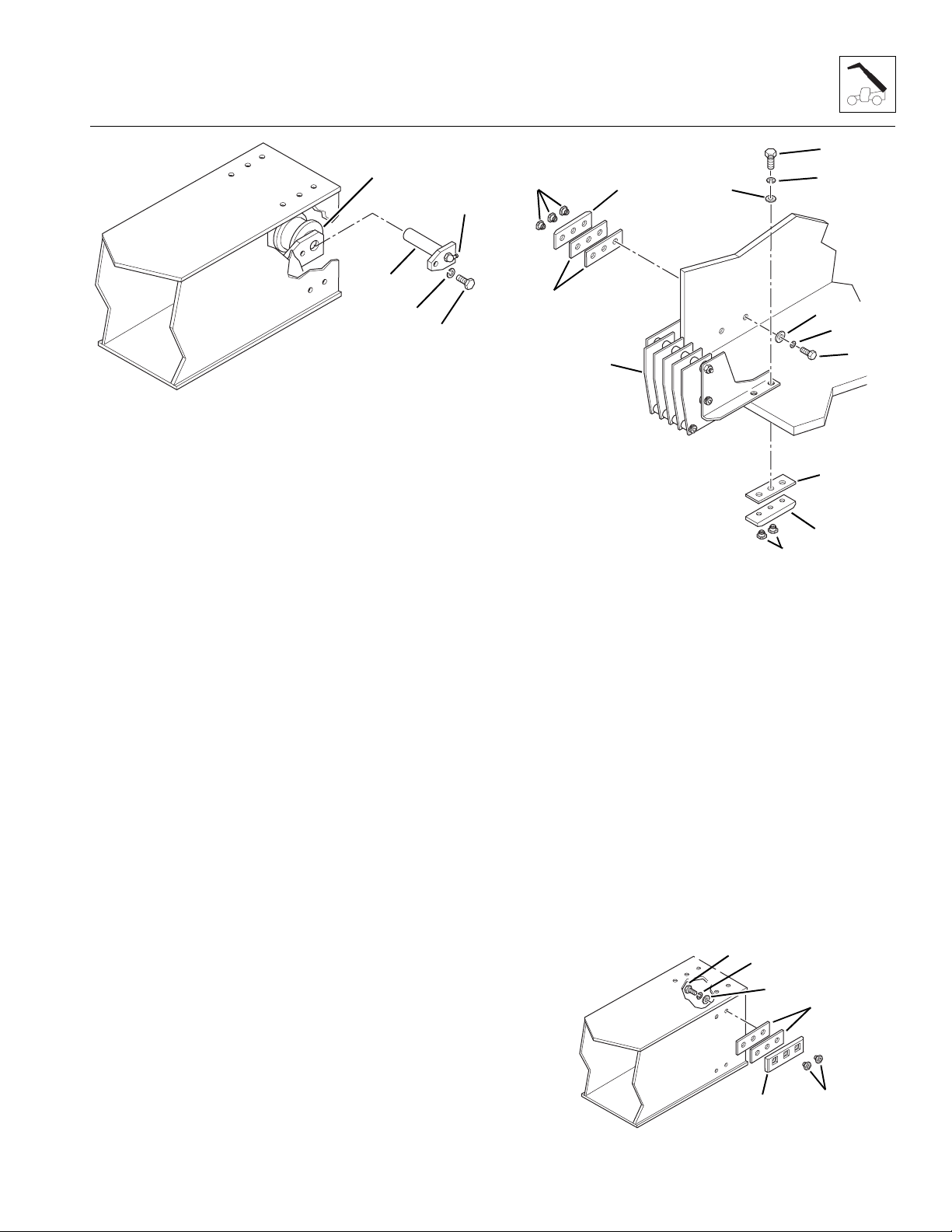
Boom
11
1
6
7
13
5
12
2
4
3
MA7290
Figure 3- 64 Install the Retract Chain Sheave
3. Install the hose reel assembly, left side and bottom
wear pads to the rear of the intermediate boom:
Note: Shim ALL side wear pads as needed to maintain
a total minimum gap of .07-.13" (1,8-3,3 mm) in the horizontal direction.
a. Install the hose reel assembly (Fig. 3 -65, 1) on
the rear of the intermediate boom, with the left
side plate to the outside of the boom wall.
b. Apply Loctite
®
242 threadlocker to the threads of
two 3/8-16 x 1" capscrews (Fig. 3-65, 2). Insert a
capscrew with a 3/8" lockwasher (3) and a 3/8"
flat washer (4) through each of the mounting
holes in the boom wall and hose reel side plate.
c. Place the wear pad shims (Fig. 3-65, 5) onto the
capscrews with the holes offset to the top.
d. Place the wear pad inserts (Fig. 3- 65, 6) into the
cavities in the wear pad (7). Be sure the inserts
are seated completely in the cavities. Place the
wear pad onto the capscrews. Be careful not to
push the wear pad inserts out of the wear pads.
e. Place the wear pad inserts (Fig. 3-65, 8) into the
wear pad cavities. Be sure that the inserts are
seated completely into the cavities.
f. Place the wear pad spacer (Fig. 3-65, 9) and the
wear pad (10) under the intermediate boom. With
the holes offset to the left, align the holes and
secure the hose reel, wear pad spacer and wear
pad to the intermediate boom. Be careful not to
push the wear pad inserts out of the wear pads.
g. Apply Loctite
®
242 threadlocker to the threads of the
two 3/8-16 x 1-1/2" capscrews (Fig. 3-65, 11). Insert
a capscrew with a 3/8" lockwasher (12) and a 3/8"
flat washer (13) through each of the mounting holes
in the right side plate of the hose reel assembly.
h. Torque all hose reel/wear pad mounting capscrews
to 31 ±3 lb/ft (42 ±4 Nm).
i. Fill all wear pad cavities with a good grade of
lithium-based EP grease.
5
4
3
1
2
9
10
8
Figure 3 -65 Install the Hose Reel Assembly and
Lower Left and Bottom Wear Pads
MA7950
4. Install the side wear pads on the rear of the
intermediate boom:
a. Apply Loctite
®
242 threadlocker to the threads of
the 3/8-16 x 3/4" capscrews (Fig. 3-66, 1). Insert
a capscrew with a 3/8" lockwasher (2) and a 3/8" flat
washer (3) through each of the wear pad mounting
holes in the side plates of the intermediate boom.
b. Place the wear pad shims (Fig. 3 -66, 4) onto the
capscrews. Place the shims onto the capscrews
with the holes offset to the center. Place the wear
pad inserts (5) into the cavities in the wear pad
(6). Be sure the inserts are seated completely in
the cavities. Be careful not to push the wear pad
inserts out of the wear pads.
c. Torque all wear pad mounting capscrews to
31 ±3 lb/ft (42 ±4 Nm).
d. Fill all wear pad cavities with a good grade of
lithium-based EP grease.
1
2
3
4
6
Figure 3- 66 Install the Intermediate Boom Side Wear Pads
5
MA6850
Model 6036 Legacy
3.29

Boom
Note: Shim ALL upper rear wear pads as needed to
maintain a total maximum gap of .06" (1,5 mm) at the
rear of the pads and maintain a total minimum gap of
.07-.13" (1,8-3,3 mm) in the vertical direction.
5. Install the wear pads to the top of the intermediate
boom. Position the wear pads so the outside pads
are offset to the outside and the center pad is offset
to the right as seen in Fig. 3-67.
a. Place the wear pad shims (Fig. 3 -67, 1) onto the
top of the boom. Align the holes in the shims with
the holes in the boom. Place the wear pad
inserts (2) into the cavities in the wear pad (3).
Be sure the inserts are seated completely in the
cavities.
b. Apply Loctite
®
242 threadlocker to the threads of
the 3/8-16 x 1" capscrews (Fig. 3-67, 4). Insert a
capscrew with a 3/8" lockwasher (5) and a 3/8"
flat washer (6) through each of the mounting
holes in the top of the intermediate boom. Be
careful not to push the wear pad inserts out of
the wear pads.
c. Torque all wear pad mounting capscrews to
31 ±3 lb/ft (42 ±4 Nm).
d. Fill all wear pad cavities with a good grade of
lithium-based EP grease.
2
3
1
6
5
4
6. Before installing the intermediate boom into the
outer boom, place a string for each hose in the outer
boom (heavy enough to pull the attachment tilt and
auxiliary hydraulic hoses) down the inside of the
outer boom. Allow the strings to hang out the rear of
the boom. Pull the other end out the opening on the
left side of the boom where the hoses will exit the
boom. Position the strings all the way to the left side
of the outer boom.
7. Using a hoist capable of lifting 5000 lbs (2268 kg)
and slings, lift the intermediate boom. Carefully slide
the hose reel end of the boom into the front of the
outer boom. Push the boom in until the rod end of
the extend/retract cylinder lines up with the mounts
on the intermediate boom.
8. Remove the slings and the hoist from the
intermediate boom.
9. Install the side wear pads on the outer boom:
a. Slide the intermediate boom over to one side as
far as it will go, to allow wear pad installation.
b. Place the wear pad inserts (Fig. 3-68, 1) into the
cavities of the side wear pads (2). Place the
shims (3) onto the wear pad and align the holes.
c. Apply Loctite
®
242 threadlocker to the threads of
the 3/8-16 x 3/4" capscrews (Fig. 3-68, 4). Slide
the wear pad with shims between the intermediate
boom and the outer boom with the offset of each
wear pad away from the center. Align the holes
and secure in place with the capscrews (4), 3/8"
lockwashers (5) and 3/8" flat washers (6). Be
careful not to push the wear pad inserts out of
the wear pads.
d. Torque all wear pad mounting capscrews to
31 ±3 lb/ft (42 ±4 Nm).
e. Fill all wear pad cavities with a good grade of
lithium-based EP grease.
f. Slide the intermediate boom all the way over to
the other side to allow wear pads installation.
Repeat Steps a-e to install the side wear pads on
the other side of the outer boom.
MA7310
Figure 3- 67 Install the Intermediate Boom Top Wear Pads
3.30
Model 6036 Legacy
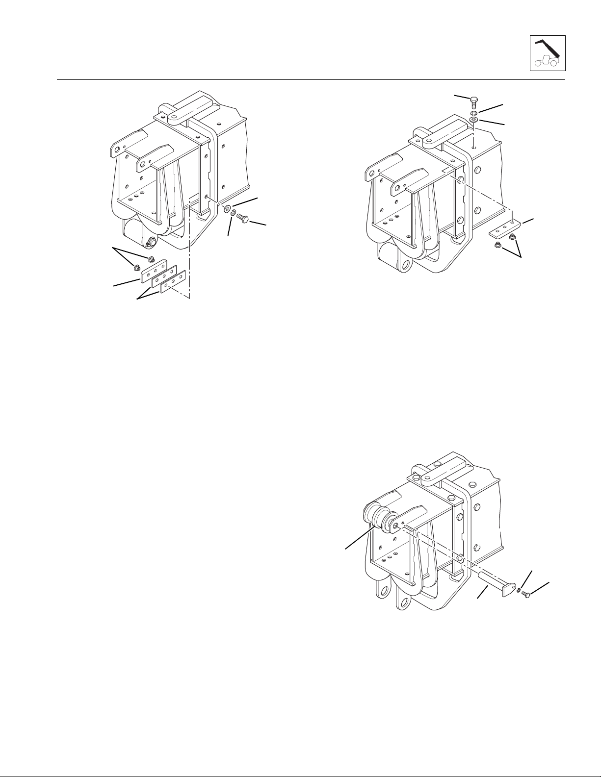
Boom
6
4
1
5
2
3
Figure 3- 68 Install the Outer Boom Side Wear Pads
MA7450
10. Install the top wear pads to the inside of the outer
boom:
a. Place the wear pad inserts (Fig. 3- 69, 1) into the
cavities of the top wear pads (2).
b. Apply Loctite
®
242 threadlocker to the threads of
the 3/8-16 x 1" capscrews (Fig. 3-69, 3). Slide
the wear pads in between the intermediate boom
and the outer boom with the offset of each wear
pad away from the center. Align the holes, and
secure in place with the capscrews (3), 3/8"
lockwashers (4) and 3/8" flat washers (5). Be
careful not to push the wear pad inserts out of
the wear pads.
c. Torque all wear pad mounting capscrews to
31 ±3 lb/ft (42 ±4 Nm).
d. Fill all wear pad cavities with a good grade of
lithium-based EP grease.
3
4
5
2
1
MA7460
Figure 3- 69 Install the Outer Boom Top Wear Pads
11. Place the double extend chain sheave (Fig. 3-70, 1)
between the mounts at the front of the intermediate
boom. Insert the sheave pin (2) through the mounts
and the double sheave. Align the mounting hole in
the sheave pin with the threaded hole in the sheave
mount, and secure in place with the 1/2-13 x 1"
capscrew (3) and the 1/2" lockwasher (4). Tighten
securely.
12. After the sheave is assembled, apply a good grade
of multi-purpose grease to the grease fitting. Turn
the sheave by hand to distribute the grease evenly.
Model 6036 Legacy
1
2
Figure 3- 70 Install the Extend Chain Sheave
4
3
MA7470
3.31

Boom
13. Use a hoist and sling to lift the rod end of the extend
cylinder (Fig. 3 -71, 1) up. Align the rod end of the
extend cylinder with the mounts (2) at the front of the
intermediate boom.
14. Coat the extend cylinder rod end pin (Fig. 3- 71, 3)
with an anti-seize compound. Insert the rod end pin
through the mounts and secure in place with the
retaining rings (4). Be sure the retaining rings are
seated securely in the grooves on the pin.
4
1
2
3
7
6
4
7
6
5
7
6
Figure 3- 72 Install the Intermediate
Boom Front Wear Pads
4
MA7490
2
1
2
Figure 3- 71 Install the Extend/Retract
Cylinder Rod End Pin
3
4
15. Install the intermediate boom front wear pads:
a. Place the wear pad inserts (Fig. 3 -72, 1) into the
cavities of the front bottom wear pads (2).
b. Place the wear pads and spacers (Fig. 3-72, 3)
into the intermediate boom with the offset of the
wear pads toward the outside.
c. Apply Loctite
®
242 threadlocker to the threads of
two 3/8-16 x 1-3/4" capscrews (Fig. 3-72, 4) and
one 3/8-16 x 1" capscrew (5). Align the holes and
secure with the capscrews (4 and 5), 3/8"
lockwashers (6) and 3/8" flat washers (7). Be
careful not to push the wear pad inserts out of
the wear pads.
d. Torque all wear pad mounting capscrews to
31 ±3 lb/ft (42 ±4 Nm).
e. Fill all wear pad cavities with a good grade of
lithium-based EP grease.
MA7480
16. Install the inner boom, extend chain and attaching
hardware. (Refer to Section 3.3.6, “Inner Boom
Installation.”)
17. Clean up all debris, hydraulic fluid, etc., in, on, near
and around the vehicle.
WARNING: Avoid prolonged engine
operation in closed areas without adequate
ventilation. Failure to properly ventilate exhaust
fumes can result in death or serious personal
injury.
18. Start the engine and operate all boom functions
several times. Check the chain tension again and
adjust as necessary (refer to Section 3.3.7, c. “Boom
Chain Tension Check” and Section 3.3.7, d. “Boom
Extend Chain Tension Adjustment”).
19. Check for leaks, and check the hydraulic fluid level in
the tank; add fluid if required.
20. Apply grease at all lubrication points (grease fittings).
(Refer to Model 6036 Legacy Owners/Operators
Manual.)
3.32
Model 6036 Legacy

Boom
3.3.6 Inner Boom Installation
WARNING: Wear protective footwear
with reinforced toe caps and slip-resistant soles.
Failure to comply can result in foot or other
bodily injury from crushing, slipping or falling.
WARNING: NEVER lift a heavy object
without the help of at least one assistant or a
suitable sling and hoist. Failure to comply can
result in death or serious personal injury.
IMPORTANT: Light lubrication of the boom wear
surfaces with a rust inhibitor/lubricant such as LPS 3 or
equivalent is recommended to keep the boom wear
surfaces lubricated properly. Light lubrication of the boom
wear surfaces is also recommended in salt air climates
and when the vehicle is stored, to help prevent rusting.
1. Stretch the attachment tilt and auxiliary hoses
(if equipped) out straight on a flat surface. Measure
from the end of the male end (Fig. 3-73, 1) of each
hose back the distance (2) listed below, and apply
tape (3) around each hose at that point. The tape is
for proper tensioning of the hoses during reassembly
of the hose clamps.
• Left Auxiliary Hydraulic Hose: 172-1/2" (438 cm)
• Right Auxiliary Hydraulic Hose: 171" (434 cm)
• Attachment Tilt Retract Hose: 174-1/2" (443 cm)
• Attachment Tilt Extend Hose: 170" (432 cm)
Note: Steps 2 and 3 apply to vehicles not equipped with
auxiliary hydraulics. If the vehicle is equipped with
auxiliary hydraulics, proceed to Step 4.
2. Slide the female ends of the two attachment tilt
hoses (Fig. 3 -74, 1 and 2) through the inner boom
and out to the gooseneck. Keep the hoses next to
each other as they are being pushed through the
inner boom.
At the opening in the gooseneck, pull both hoses
out. Be careful not to cross the hoses as you pull
them out. Label the left side hose (Fig. 3-74, 1) as
“Retract” and the right side hose (2) as “Extend.”
Label the hoses the same on the male ends.
1
2
Figure 3- 74 Install the Attachment Tilt Hoses
MA6930
2
3
1
Figure 3- 73 Hose Measurement for Tensioning
Model 6036 Legacy
MA7380
3.33

Boom
3. Assemble the hose clamps to the floor of the inner
boom. Keep the two hoses on the left and right sides
as they come out of the rear of the inner boom:
a. Place a 5/16" lockwasher (Fig. 3-75, 1) and flat
washer (2) onto each 5/16-18 x 3-1/2" capscrew
(3), and insert the capscrews through the clamp
cover plate (4).
b. Place a hose clamp half (Fig. 3-75, 5) onto the
capscrews. Place the left attachment tilt hose (6)
and a hose clamp half (5) onto the capscrews.
Secure the capscrews to the floor of the inner
boom. Tighten the capscrews only enough to
hold the hoses in place.
c. Repeat Steps a and b to install the right attachment
tilt hose (Fig. 3 -75, 7).
d. Position the attachment tilt hoses (Fig. 3-75, 6
and 7) with the edge of the tape (8) at the hose
clamps. Hold the attachment tilt hoses in this
position, and tighten the capscrews securely.
Proceed to Step 7.
3
1
2
4
4. Slide the female ends of the two attachment tilt
hoses (Fig. 3-76, 1 and 2) down the inner boom and
out to the gooseneck. Keep the hoses next to each
other as they are being pushed through the inner
boom.
At the opening in the gooseneck, pull both hoses
out. Be careful not to cross the hoses as you pull
them out. Label the left side hose (Fig. 3-76, 1) as
“Retract” and the right side hose (2) as “Extend.”
Label the hoses the same on the male ends.
5. Slide the female end of the two auxiliary hydraulics
hoses (Fig. 3 -76, 3 and 4) through the inner boom
and out the gooseneck. Keep the auxiliary hoses to
the left and right sides of the attachment tilt hoses
(1 and 2).
At the opening in the gooseneck, pull both hoses out
and down toward the bulkhead plate for the couplers.
Keep the left side hose (Fig. 3-76, 3) on the left side,
and label that hose as “Female Coupler.” Label both
ends of the hose. Keep the right side hose (4) on the
right side, and label that hose as “Male Nipple.”
Label both ends of the hose.
5
6
7
8
Figure 3- 75 Install the Attachment Tilt Hose Clamps
Inside the Inner Boom
MA6950
1
2
3
4
Figure 3- 76 Install the Attachment Tilt and
Auxiliary Hydraulics Hoses
MA6940
3.34
Model 6036 Legacy

6. Assemble the hose clamps to the floor of the inner
boom. Keep the four hoses in line (left to right) as
they come out of the rear of the inner boom:
a. Place a 5/16" lockwasher (Fig. 3-77, 1) and
5/16" flat washer (2) onto each 5/16-18 x 5"
capscrew (3), and insert the capscrews through
the clamp cover plate (4).
b. Place a 3/4" diameter hose clamp half (Fig. 3-77, 5)
onto the capscrews. Place the left auxiliary
hydraulic hose (6) and another 3/4" diameter
hose clamp half (5) onto the capscrews.
c. Place a 5/8" diameter hose clamp half (Fig. 3-77, 7),
left attachment tilt hose (8) and another 5/8"
diameter hose clamp half (7) onto the capscrews.
d. Repeat Steps a-c to install the right attachment
tilt (Fig. 3 -77, 9) and right auxiliary hydraulic
hoses (10).
e. Position the attachment and auxiliary hydraulic
tilt hoses (Fig. 3 -77, 6, 7, 9 and 10) with the
edges of the tape (11) at the hose clamps. Hold
the hoses in position, and tighten the capscrews
securely.
Boom
3
1
4
6
8
6
8
2
5
7
10
9
11
MA6960
Figure 3- 77 Install the Attachment Tilt and Auxiliary
Hydraulic Hose Clamps to the Inside of the Inner Boom
Model 6036 Legacy
3.35

Boom
1
Note: Shim ALL upper rear wear pads as needed to
maintain a total maximum gap of .06" (1,5 mm) at the
rear of the pads and maintain a total minimum gap of
.07-.13" (1,8-3,3 mm) in the vertical direction.
Note: Shim ALL side wear pads as needed to maintain
a total minimum gap of .07-.13" (1,8-3,3 mm) in the horizontal direction.
7. Install all wear pads on the rear of the inner boom:
a. Place the wear pad inserts (Fig. 3 -78, 1) into the
cavities of the inner boom “Top Left” and “Top
Right” side wear pads (2).
b. Place the wear pad, spacer (Fig. 3- 78, 3) and
shims (4) onto the inner boom with the offset of
the wear pads toward the outside edge.
c. Apply Loctite
the 3/8-16 x 1-3/4" capscrews (Fig. 3-78, 5).
Secure the wear pad with the capscrews (5), 3/8"
lockwashers (6) and flat washers (7). Be careful
not to push the wear pad inserts out of the wear
pads.
d. Place the wear pad inserts (Fig. 3 -78, 8) into the
cavities of the inner boom “Left” and “Right” side
wear pads (9).
e. Place the wear pads and shims (Fig. 3-78, 10),
onto the inner boom with the offset of the wear
pads toward the top and bottom edges.
f. Apply Loctite
the 3/8-16 x 1-3/4" capscrews (Fig. 3-78, 11).
Align the holes, and secure the wear pads in
place with the capscrews (11), 3/8" lockwashers
(12) and flat washers (13). Be careful not to push
the wear pad inserts out of the wear pads.
g. Place the wear pad inserts (Fig. 3 -78, 14) into
the cavities of the inner boom “Bottom” wear pad
(15).
h. Place the wear pad and spacer (Fig. 3-78, 16)
onto the bottom of the inner boom with the offset
of the wear pads toward the right side.
i. Apply Loctite
the 3/8-16 x 1-1/4" capscrews (Fig. 3-78, 17).
Align the holes, and secure the wear pads in
place with the capscrews (17), 3/8" lockwashers
(18) and flat washers (19). Be careful not to push
the wear pad inserts out of the wear pads.
j. Torque all wear pad mounting capscrews to
31 ±3 lb/ft (42 ±4 Nm).
k. Fill all wear pad cavities with a good grade of
lithium-based EP grease.
®
242 threadlocker to the threads of
®
242 threadlocker to the threads of
®
242 threadlocker to the threads of
2
3
4
17
18
7
6
5
19
11
12
13
16
8
15
14
Figure 3- 78 Install the Inner Boom Wear Pads
MA6900
Note: ALWAYS replace elastic-lined nuts with new
elastic-lined nuts to help ensure proper fastening.
8. Lay the two extend chains on the top of the inner
boom with the threaded clevis ends (Fig. 3-79, 1)
toward the rear of the boom. Coat the threads on
each clevis with multi-purpose grease, and insert the
clevis’ through the holes in the anchor plate (2).
9. Install one 3/4" flat washer (Fig. 3-79, 3) onto each
clevis. Install a new 3/4-16 elastic locknut (4) onto
each clevis. Tighten the elastic locknut far enough so
the threads are even with the top of the locknut.
1
2
4
3
MA7110
10
9
3.36
Figure 3- 79 Install the Extend Chains on the Inner Boom
Model 6036 Legacy

Boom
10. At the rear of the inner boom, place the male ends of
the hoses (attachment tilt and optional auxiliary
hydraulics) inside the inner boom. Be sure the hoses
are coiled up and inside the boom completely.
Note: Use a hoist with a lifting capacity of 5000 lbs
(2268 kg) and slings to install the inner boom.
11. Carefully slide the end of the boom into the front of the
intermediate boom. Readjust the position of the sling
as needed to help balance the boom during installation.
Insert the inner boom into the intermediate boom as
far as possible.
12. Install the side wear pads on the intermediate boom:
Note: Shim ALL side wear pads as needed to maintain
a total minimum gap of .07-.13" (1,8-3,3 mm) in the
horizontal direction.
a. Slide the inner boom over to one side as far as it
will go, to allow wear pad installation.
b. Place the wear pad inserts (Fig. 3 -80, 1) into the
cavities of the side wear pads (2). Place the
shims (3) onto the wear pad and align the holes.
c. Apply Loctite
®
242 threadlocker to the threads of
the 3/8-16 x 3/4" capscrews (Fig. 3- 80, 4). Slide
the wear pad with shims between the inner boom
and the intermediate boom with the offset of each
wear pad away from the center. Align the holes
and secure in place with the capscrews (4), 3/8"
lockwashers (5) and 3/8" flat washers (6). Be
careful not to push the wear pad inserts out of the
wear pads.
d. Torque all wear pad mounting capscrews to
31 ±3 lb/ft (42 ±4 Nm).
e. Fill all wear pad cavities with a good grade of
lithium-based EP grease.
f. Repeat Steps a-e to install the side wear pads on
the other side of the intermediate boom.
13. Install the top wear pads on the inside of the
intermediate boom:
a. Place the wear pad inserts (Fig. 3- 81, 1) into the
cavities of the top wear pads (2).
®
b. Apply Loctite
242 threadlocker to the threads of
the 3/8-16 x 1-1/2" capscrews (Fig. 3-81, 3).
Slide the wear pads with the spacers (4) between
the inner boom and the intermediate boom, with
the offset of each wear pad toward the center.
Align the holes and secure in place with the
capscrews (3) and 3/8" lockwashers (5). Be
careful not to push the wear pad inserts out of
the wear pads.
c. Torque all wear pad mounting capscrews to
31 ±3 lb/ft (42 ±4 Nm).
d. Fill all wear pad cavities with a good grade of
lithium-based EP grease.
3
5
5
4
2
1
2
3
Figure 3- 80 Install the Intermediate
Boom Front Side Wear Pads
Model 6036 Legacy
1
Figure 3- 81 Install the Intermediate
Boom Front Wear Pads
MA8060
14. Pull the male ends of the hoses out the rear of the
inner boom. Stretch the hoses out straight behind
the vehicle.
6
5
4
MA8050
3.37

Boom
Note: Steps 15-17 apply to vehicles not equipped with
auxiliary hydraulics. If the vehicle is equipped with
auxiliary hydraulics, proceed to Step 18.
15. Assemble the hoses to the hose reel at the rear of
the boom:
IMPORTANT: Keep the hoses in the same order as they
come from the hose clamps. DO NOT allow the hoses to
cross.
Note: Loosen the nuts and capscrews only enough to
pull the hoses around the hose reel.
a. Loosen, but DO NOT remove, the elastic
locknuts (Fig. 3-82, 1, 2 and 3) on the upper
retaining capscrew (4), lower retaining capscrew
(5) and center hose reel shoulder bolt (6).
b. Loosen, but DO NOT remove, the wear pad
mounting capscrews (Fig. 3-82, 7 and 8) securing
the hose reel assembly to the intermediate
boom.
c. Place the left side attachment tilt hose (Fig. 3 -82,
9) into the second position from the left on the
hose reel.
d. Place the right side attachment tilt hose
(Fig. 3-82, 10) into the second position from the
right on the hose reel.
16. Tie the strings (positioned inside the outer boom
during the outer boom installation) to the male end of
each of the attachment tilt hoses coming off the
bottom hose reel assembly.
IMPORTANT: Keep the hoses in the same order as they
come off the hose reel. DO NOT allow the hoses to
cross.
17. Working from the front of the boom, pull each hose
through the boom assembly:
a. Pull the right side attachment tilt hose (Fig. 3-83, 1)
through the boom assembly. Pull the hose
through the opening (3) at the bottom of the outer
boom.
b. Pull the left attachment tilt hose (Fig. 3-83, 2)
through the boom assembly, keeping the left
attachment tilt hose to the left side of the hose
already down the boom. Pull the hose through
the opening (3) at the bottom of the outer boom.
c. Tighten the elastic locknuts (Fig. 3-82, 1, 2 and
3) on the hose reel assembly, and wear pad
mounting capscrews (Fig. 3-82, 7 and 8).
Proceed to Step 21.
1
2
3
7
10
4
9
2
8
3
1
5
Figure 3- 82 Assemble Hoses to Hose Reel Assembly
6
MA8220
1
2
MH1700
Figure 3- 83 Pull the Attachment Tilt Hoses Between the
Outer and Intermediate Boom Sections
3.38
Model 6036 Legacy

Boom
18. Assemble the hoses to the hose reel assembly at the
rear of the boom:
IMPORTANT: Keep the hoses in the same order as they
come from the hose clamps. DO NOT allow the hoses to
cross.
Note: Loosen the nuts enough to pull the hoses around
the hose reel.
a. Loosen, but DO NOT remove, the elastic
locknuts (Fig. 3-84, 1, 2 and 3) on the upper
retaining capscrew (4), lower retaining capscrew
(5) and center hose reel shoulder bolt (6).
b. Loosen, but DO NOT remove, the wear pad
mounting capscrews (Fig. 3-84, 7 and 8)
securing the hose reel assembly to the intermediate boom.
c. Place the left side auxiliary hydraulic hose
(Fig. 3-84, 9) into the left position on the hose
reel.
d. Place the left side attachment tilt hose
(Fig. 3-84, 10) into the second position from the
left on the hose reel.
e. Place the right side attachment tilt hose
(Fig. 3-84, 11) into the second position from the
right on the hose reel.
f. Place the right side auxiliary hydraulic hose
(Fig. 3-84, 12) into the right position on the hose
reel.
g. Place the attachment tilt hoses and the auxiliary
hydraulic hoses around the hose reel.
19. Tie the strings (positioned inside the outer boom
during the outer boom installation) to the male end of
each of the attachment tilt and auxiliary hydraulic
hoses coming off the bottom hose reel assembly.
20. Working from the front of the boom, pull each hose
through the boom assembly:
IMPORTANT: Keep the hoses in the same order as they
come off the hose reel. DO NOT allow the hoses to cross.
a. Pull the right side auxiliary hydraulic hose
(Fig. 3-85, 1) through the boom assembly. Pull
the hose out the opening (2) at the bottom of the
outer boom.
b. Pull the right side attachment tilt hose (Fig. 3-85, 3)
through the boom assembly. Keep the right side
attachment tilt hose to the left of the right side
auxiliary hydraulic hose. Pull the hose out the
opening (2) at the bottom of the outer boom.
c. Pull the left side attachment tilt hose (Fig. 3-85, 4)
through the boom assembly, using the hoses
already down the boom as a guide. Keep the left
side attachment tilt hose to the left of the hoses
already installed. Pull the hose out the opening
(2) at the bottom of the outer boom.
d. Pull the left side auxiliary hydraulic hose
(Fig. 3-85, 5) through the boom assembly, using
the hoses already down the boom as a guide.
Keep the left side auxiliary hydraulic hose to the
left of the hoses already installed. Pull the hose
out the opening (2) at the bottom of the outer
boom.
e. Tighten the elastic locknuts (Fig. 3-84, 1, 2 and
3) on the hose reel assembly and wear pad
mounting capscrews (Fig. 3-84, 7 and 8).
10
7
9
11
4
12
2
3
8
1
5
Figure 3- 84 Assemble the Hoses to Hose Reel Assembly
Model 6036 Legacy
6
MA7130
2
Figure 3- 85 Pull the Attachment Tilt and Auxiliary
Hydraulic Hoses Between the Outer and
Intermediate Boom Sections
21. Remove the strings from the hoses.
1
3
4
5
3
4
1
5
MH1410
3.39

Boom
22. At the front of the outer boom, connect the hose
assemblies and tube assemblies to the mounting plate.
Note: ALWAYS use new o-rings when servicing the
vehicle.
23. Install new o-rings into the fittings. Lubricate o-rings
with clean hydraulic oil.
24. Remove the plugs and caps from the hoses and
fittings, and connect the attachment tilt (Fig. 3 -86, 5)
and auxiliary hydraulic (6) (if equipped) hoses to the
fittings on the boom tube bulkhead bracket.
25. Lubricate the radius (Fig. 3-86, 1) in the outer boom
with soap and water to allow the hoses to slide easily
when tensioning the hoses.
Note: Steps 26 and 27 refer to vehicles without auxiliary
hydraulics. If your vehicle is equipped with auxiliary
hydraulics, proceed to Step 28.
26. Connect the right side attachment tilt hose (Fig. 3-86, 2)
to the right side attachment tilt tube assembly (3).
Tighten the tube assembly nut securely to hold the
tube to the hose. Tighten the other end of the tube
assembly to the bulkhead fitting at the rear of the boom.
27. Connect the left side attachment tilt hose (Fig. 3 -86, 4)
to the left side attachment tilt tube assembly (5).
Tighten the tube assembly nut securely to hold the
tube to the hose. Tighten the other end of the tube
assembly to the bulkhead fitting at the rear of the
boom. Proceed to Step 32.
28. Connect the right side attachment tilt hose (Fig. 3-87, 1)
to the upper right side attachment tilt tube assembly (2).
Tighten the tube assembly nut securely to hold the
tube to the hose. Tighten the other end of the tube
assembly to the bulkhead fitting at the rear of the
boom.
29. Connect the left side attachment tilt hose (Fig. 3-87, 3)
to the upper left side attachment tilt tube assembly (4).
Tighten the tube assembly nut securely to hold the
tube to the hose. Tighten the other end of the tube
assembly to the bulkhead fitting at the rear of the
boom.
30. Connect the right side auxiliary hydraulic hose
(Fig. 3-87, 4) to the lower right side auxiliary
hydraulic tube assembly (6). Tighten the tube
assembly nut securely to hold the tube to the hose.
Tighten the other end of the tube assembly to the
bulkhead fitting at the rear of the boom.
31. Connect the left side auxiliary hydraulic hose
(Fig. 3 -87, 7) to the lower left side auxiliary hydraulic
tube assembly (8). Tighten the tube assembly nut
securely to hold the tube to the hose. Tighten the
other end of the tube assembly to the bulkhead
fitting at the rear of the boom.
1
~
2
3
Figure 3- 86 Connect the Attachment Tilt Hoses
to the Tube Assemblies
3.40
5
3
4
4
5
3
5
1
2
7
4
8
2
6
8
6
MA7420
Figure 3- 87 Connect the Attachment Tilt and Auxiliary
MA7980
Hydraulic Hoses and to the Tube Assemblies
Model 6036 Legacy

Boom
32. Place the retract chain (Fig. 3-88, 1) around the
retract chain sheave on the right side of the boom.
Stretch the chain forward and place the clevis
between the two anchor plates (2). Align the hole in
the clevis with the second hole from the rear of the
anchor plates.
33. Insert the shoulder bolt (Fig. 3-88, 3) from the top
down in the same hole as recorded in the removal
procedure, and secure in place with a new 3/8-16
elastic locknut (4). Tighten the locknut securely.
3
2
1
2
4
Figure 3- 88 Connect the Retract Chain
MH2340
34. Assemble the two extend chains to the outer boom
mount. If the yoke plates were removed from the
extend chains, continue with next step. If the yoke
plates were not replaced, proceed to Step 37.
5
2
1
4
1
6
Figure 3- 89 Extend Chains and Yoke Plates
3
SH1870
Note: ALWAYS replace elastic-lined nuts with new
elastic-lined nuts to help ensure proper fastening.
37. Align the holes in the yoke plates (Fig. 3-90, 1) with
the hole in the mount on the outer boom. Coat the
shoulder bolt (2) with anti-seize compound, and
insert the shoulder bolt through the yoke plates and
the mount on the boom. Secure in place with a new
1/2-13 elastic locknut (3). Tighten the locknut
securely, but ensure that the yoke plates pivot freely.
2
1
Note: ALWAYS replace elastic-lined nuts with new
elastic-lined nuts to help ensure proper fastening.
35. Assemble the yoke plates (Fig. 3-89, 1) to the mount
on the front of the outer boom. Coat the shoulder
bolt (2) with anti-seize compound, and insert the
shoulder bolt through a yoke plate (1), the mount on
the boom and through a second yoke plate (1) on
the bottom. Secure in place with a new 1/2-13 elastic
locknut (3). Tighten the locknut securely, but the
ensure that the yoke plates pivot freely.
36. Assemble the clevis’ on the two extend chains
(Fig. 3-89, 4) between the yoke plates. Align the
holes in each clevis with the holes in the yoke plates.
Coat the hex socket head capscrews (5) with antiseize compound, and insert the capscrews through
the yoke plates and the clevis. Secure in place with
new 3/8-16 elastic locknuts (6). Tighten the locknuts
securely, but ensure that the extend chain clevis’
pivot freely.
3
MA7810
Figure 3- 90 Connect the Extend Chains
to the Outer Boom
Model 6036 Legacy
3.41

Boom
Note: ALWAYS use new o-rings when servicing the vehicle.
38. Install new o-rings into the fittings. Lubricate o-rings
with clean hydraulic oil.
39. With optional auxiliary hydraulics: If the inner
boom has been replaced with a new boom, the
auxiliary hydraulic fittings need to be reassembled:
a. Assemble the two bulkhead fittings (Fig. 3-91, 1)
from the original boom to the bulkhead plate (2)
inside the gooseneck (3). Insert the bulkhead
fittings from the bottom of the bulkhead plate,
and secure in place with the bulkhead fitting nut
(4) on the top side. Tighten securely.
b. Assemble the male nipple (Fig. 3-91, 5) and dust
cap (6) to the right side swivel connector fitting.
Tighten the swivel connector and male nipple
securely. Assemble the dust cap onto the male
nipple.
c. Assemble the female coupler (Fig. 3-91, 7) and
dust plug (8) to the left side swivel connector
fitting. tighten the swivel connector and female
coupler securely. Insert the dust plug into the
female coupler.
d. Assemble the left auxiliary hydraulic hose
(Fig. 3-91, 9) labeled “Female Coupler” from
inside the gooseneck to the female coupler
bulkhead fitting. Tighten securely.
e. Assemble the right auxiliary hydraulic hose
(Fig. 3-91, 10) labeled “Male Nipple” from inside
the gooseneck to the male nipple bulkhead
fitting. Tighten securely.
40. Use a hoist and slings to position the attachment tilt
cylinder (Fig. 3 -92, 1) inside the gooseneck (2). Be
sure that the attachment tilt cylinder is positioned
with the tube for the rod end positioned inside the
gooseneck.
41. Coat the base end pivot pin (Fig. 3 -92, 3) with antiseize compound. Align the hole in the cylinder base
end with the mounting holes in the gooseneck, and
insert the pivot pin through the gooseneck. Secure
the pivot pin to the gooseneck with the two retaining
rings (4). Be sure the retaining rings are seated
squarely in the grooves on the pivot pin.
4
2
3
4
1
MA6450
3.42
3
10
9
4
1
5
6
8
Figure 3- 91 Install the Auxiliary
Hydraulic Coupler and Nipple
Figure 3- 92 Install the Attachment Tilt
Cylinder Base End Pivot Pin
42. Install the quick attach on the gooseneck. (Refer to
Section 3.4.4, “Quick Attach Installation.”)
43. Connect the attachment tilt hoses from the rear of
the gooseneck to the fittings on the base end of the
attachment tilt cylinder. Assemble the left side hose
(Fig. 3-93, 1) labeled as “Retract” to the retract port
(upper) fitting (2) on the base end of the attachment
tilt cylinder. Index the elbow end of the hose to
4
2
remove any undo tension and tighten the elbow
completely to the fitting on the cylinder.
44. Connect the right side hose (Fig. 3-93, 3) labeled as
1
“Extend” to the extend port (lower) fitting (4) on the
base end of the attachment tilt cylinder. Index the
7
MA6410
elbow end of the hose to remove any undo tension
and tighten the elbow completely to the fitting on the
cylinder.
Model 6036 Legacy

Boom
49. Start the engine and operate all boom functions
several times. Check the chain tension again and
adjust as necessary. Check for leaks, and check the
hydraulic fluid level in the tank; add fluid if required.
50. Apply grease to all lubrication points (grease fittings).
(Refer to Model 6036 Legacy Owners/Operators
Manual.)
51. Install the rear cover (Fig. 3-94, 1), by inserting the
capscrew (2) at the top of the cover into the hole (3)
in the top of the boom. Secure the rear cover using
1
2
4
one thumbscrew (4), one internal-tooth lockwasher
(5) and one flat washer (6).
3
MA6400
Figure 3- 93 Connect the Attachment Tilt Cylinder Hoses
45. Measure all wear pad gaps. (Refer to Model 6036
Legacy Owners/Operators Manual for wear pad gap
dimensions and wear pad thickness requirements.)
Add or remove shims as required. Replace the wear
pads with new ones, if needed.
46. Check and adjust the boom chain.
47. Clean up all debris, hydraulic fluid, etc., in, on, near
and around the vehicle.
48. Connect the battery negative (-) ground cable.
WARNING: Avoid prolonged engine
operation in closed areas without adequate
ventilation. Failure to properly ventilate
exhaust fumes can result in death or serious
personal injury.
WARNING: Hydraulic oil leaking under
pressure can penetrate the skin and cause
severe personal injury. DO NOT use your hand
or any part of your body to check the hydraulic
leaks. When checking for hydraulic leaks, wear
safety glasses and gloves to help provide
protection from spraying hydraulic oil. Use a
piece of cardboard or paper to search for
leaks.
2
3
6
5
4
Figure 3- 94 Install the Boom Rear Cover
1
MA6420
Model 6036 Legacy
3.43

Boom
3.3.7 Boom Chains
This vehicle uses double extend chains to extend the
boom and a single retract chain to retract the boom. The
extend and retract chains are constructed of 3/4" pitch
links with 6 x 6 leaf lacing.
Note: DO NOT attempt to service or repair a chain.
Replace a stretched or damaged chain with a new one.
Replacement chains are shipped pre-assembled with
new clevis’.
a. Boom Chain Inspection
250
MS21702
MM2130
Figure 3- 95 Every 250 Hours of Engine Operation,
Inspect Boom Chain Condition
WARNING: Worn pins, stretched or
cracked links or corrosive environments can
cause chain failure. A chain failure could result
in uncontrolled boom movement, loss of load
or vehicle instability, and could cause death or
serious injury and/or property damage.
Under normal operating conditions the boom chains will
need to be inspected every 250 hours of operation.
Environmental conditions and dynamic impulse/shock
loads can drastically affect normal operating conditions.
Environments in which material handling vehicles
operate can vary widely from outdoor moisture to mildly
corrosive or highly corrosive industrial atmospheres, in
addition to abrasive exposures such as sand and grit.
• Moisture - Corrosive rusting reduces chain
strength by pitting and cracking.
• Temperature - Low temperature reduces chain
strength by making the metal brittle. Going in and
out of cold storage results in moisture from
condensation.
• Chemical Solutions or Vapors - Corrosive attack
on the chain components and/or the mechanical
connections between the chain components.
Cracking can be (and often is) microscopic.
Going from microscopic cracking to complete
failure can be either abrupt or may require an
extended period of time.
• Abrasives - Accelerated wearing and scoring of
the articulating members of the chain (pins and
plates), with a corresponding reduction in chain
strength. Due to the inaccessibility of the bearing
surfaces (pin surfaces and plate apertures), wear
and scoring are not readily noticeable to the
naked eye.
Dynamic shock loading can impose abnormal loads
above the endurance limit of a leaf chain.
• High velocity movement of load, followed by
sudden, abrupt stops.
• Carrying loads in suspension over irregular
surfaces such as railroad tracks, potholes and
rough terrain.
• Attempting to “inch” loads which are beyond the
rated capacity of the vehicle.
Environmental conditions and load cycles make it
impossible to predict chain life. Each specific application
should be evaluated, based on the degree of exposure,
the areas of possible operation and the types of load
cycles.
A chain replacement schedule should be established to
prevent chain failure. This schedule can be established
by frequent inspection. Based on the observations, the
frequency of inspection can be changed.
This inspection procedure development should go on until a
projected time of replacement can be predicted. A chain
by its very nature and exposure should be considered an
expendable item and a safe chain replacement schedule
should be established.
The boom chain’s normal life expectancy can be expressed
as a maximum percent of elongation. This is generally
3% of pitch. As the chain flexes back and forth over the
sheave, the bearing joints (pins and inside link plates)
gradually incur wear due to articulation.
Inspection Guidelines
1. Park the vehicle on level ground. Place the travel
select lever in (N) NEUTRAL, place the neutral lock
lever in the (N) NEUTRAL LOCK position, engage
the parking brake switch and raise the boom to a
horizontal (level) position.
3.44
Model 6036 Legacy

Boom
2. Fully extend the boom until the extend chain is taut.
Shut the engine OFF.
The extend chains will be visible for inspection with
the vehicle in this state. The retract chain can be
visually inspected, at the rear of the boom, as the
boom is slowly retracted.
While doing the chain inspection, check all chain
clevis ends for distortion or cracking and sheaves for
bearing wear or grooving from the chain.
3. Inspect the chains for the following conditions:
Elongation
When the original length (Fig. 3-96, 1) of 12.00"
(305 mm) per foot of new chain has elongated from
wear to a length (2) of 12.36" (313 mm), the chain
should be discarded and replaced. (Refer to Section
3.3.7, e. “Chain Replacement”.)
It is important to measure the chain in the section that
moves over the sheaves because it receives the most
frequent articulation. Measuring the chain near its
clevis terminals could give an inaccurate reading.
The ends of the chains, near the clevis terminals, will
not have flexed as frequently, if at all, as nearer to the
middle of the chains.
Measure across a span of 17 pins (16 links) at the
center of the extend chain. Measure from pin center
to pin center. Because the retract chain is inside the
boom, you will not be able to measure the chain.
The maximum measurement allowed is 12.36"
(313 mm). If the measurement is more than 12.36"
(313 mm), the chain should be replaced. (Refer to
Section 3.3.7, e. “Chain Replacement”.)
1
2
Edge Wear
Check the chain for wear on the link plate edges
caused by running back and forth over the sheave.
The maximum reduction of material should not
exceed 5%. This can be compared to a normal link
plate height by measuring a portion of chain that does
not run over the sheave.
The new chain link measures .713" (18 mm) (Fig. 3-97,
3). If the measurement of the worn chain is less than
.677" (17 mm) (4), the chain should be replaced.
(Refer to Section 3.3.7, e. “Chain Replacement”.)
4
Figure 3- 97 Inspect Link Plates for Edge Wear
Turning or Protruding Pins
Highly loaded chain, operating with inadequate
lubrication, can generate abnormal frictional forces
between pin and link plates. When chain is allowed to
operate in this condition, a pin or series of pins, can
begin to twist out of a chain, resulting in failure.
Examine the pin head rivets to determine if the “VEE”
flats are still in correct alignment (Fig. 3-98, 1). Chain
with rotated/displaced heads (2) or abnormal pin
protrusion (3) should be replaced immediately.
(Refer to Section 3.3.7, e. “Chain Replacement.”)
DO NOT attempt to repair the chain by welding or
driving the pin(s) back into the chain. Once the press
fit integrity between outside plates and pins has been
altered, it cannot be restored.
Any wear pattern on the pin heads or the sides of the
link plates indicates misalignment in the system. This
condition damages the chain as well as increases
frictional loading and should be corrected.
3
MM2050
Figure 3- 96 Check for Chain Elongation
Model 6036 Legacy
MM2120
2
1
Figure 3- 98 Inspect the Pin Head Rivets
3
MM2060
3.45

Boom
Cracked Plates
Inspect the chains very carefully, front and back as
well as side to side, for any evidence of cracked
plates. If any one crack is discovered, the chain
should be replaced in its entirety. (Refer to Section
3.3.7, e. “Chain Replacement”.)
It is important, however, to determine the cause of the
crack before installing a new chain so the condition
does not repeat itself.
• Fatigue Cracking - Fatigue cracks (Fig. 3-99, 4)
are a result of repeated cyclic loading beyond the
chain’s endurance limit. The size of the load and
the frequency of its occurrence are factors which
determine when fatigue failure will occur. The
loading can be continuous or intermittent
(impulse load).
• Stress Corrosion Cracking - The outside link
plates are particularly susceptible to stress
corrosion cracking (Fig. 3-99, 5). Like fatigue
cracks, these initiate at the point of highest stress
but tend to extend in an arc-like path between
holes in the pin plate. More than one crack can
often appear on a link plate. In addition to rusting,
this condition can be caused by exposure to an
acidic or caustic medium or atmosphere.
Stress corrosion is an environmentally assisted
failure. Two conditions must be present: corrosive
agent and static stress. In the chain, static stress
is present at the aperture due to the press fit pin.
No cyclic motion is required, and the plates can
crack during idle periods.
• Corrosion Fatigue Cracking - Corrosion fatigue
cracks are very similar to fatigue cracks
(Fig. 3-99, 4) in appearance. They generally
begin at the aperture and grow perpendicular to
the chain pitch line. Corrosion fatigue is not the
same as stress corrosion. Corrosion fatigue is
the combined action of an aggressive
environment and cyclic stress, not a static stress
alone, as in stress corrosion.
Other Modes of Failure
• Ultimate Strength Failure - These types of
failures are caused by overloads far in excess of
the design load. Either fractured plates
(Fig. 3 -100, 6) or enlarged holes (7) can occur. If
either of these failures occurs, the chain should
be replaced immediately. (Refer to Section 3.3.7,
e. “Chain Replacement”.)
• Tight Joints - All joints in the chain should flex
freely. Tight joints (Fig. 3 -100, 8) resist flexing
and increase internal friction, thus increasing
chain tension required to lift a given load.
Increased tension accelerates wear and fatigue
problems.
If the problem is caused by dirt or foreign
substance packed in the joints, clean and
lubricate thoroughly before re-installing the chain.
If the problem is caused by corrosion and rust or
bent pins, replace the chain. (Refer to Section
3.3.7, e. “Chain Replacement”.)
MM2090
6
7
MM2100
8
MM2110
Figure 3- 100 Other Chain Failure Modes
3.46
4
MM2070
5
MM2080
Figure 3- 99 Inspect Plates for Cracks
Model 6036 Legacy

Boom
b. Chain Lubrication
After inspection and before being returned to service,
chains must be lubricated with a quality chain lubricant
(“LUBRIPLATE” Chain & Cable Fluid, “LPS3” or
equivalent).
The lubricant must penetrate the chain joint to prevent
wear. Applying lubricant to the external surfaces will
prevent rust, but the chains should be articulated to make
sure the lubricant penetrates to the working surfaces
between the pins and links.
To prepare the chain for lubrication, the chain plates
should be brushed with a stiff brush or wire brush to clear
the space between the plates so that the lubricant can
penetrate to the working surfaces.
Lubricant may be applied with a narrow paint brush or
directly poured on, but the chain should be well flooded
with lubricant, and the boom should be extended and
retracted to be sure that the lubricant penetrates to the
working surfaces. All surplus lubricant should be wiped
away from the external surfaces. DO NOT use a solvent
for this wiping operation.
Regular application of lubricant is necessary to make
sure that all working surfaces are adequately lubricated.
In extremely dusty conditions, it may be necessary to
lubricate the chains more often.
Lubrication of chains on vehicles working consistently in
extreme hot or cold conditions requires special
consideration. It is important that a reputable lubrication
specialist, an authorized JLG Authorized Service Center
(ASC) or the vehicle distributor be consulted for
guidance.
c. Boom Chain Tension Check
1. Start the engine. Place the travel select lever in (N)
NEUTRAL, move the neutral lock lever to the
NEUTRAL LOCK position and engage the parking
brake switch.
2. With the engine at idle, purge all air from the hydraulic
system by slowly raising and lowering the boom
several times. Raise the boom to a horizontal (level)
position.
3. Slowly extend the boom, and retract it about halfway.
Fully extend the boom, then retract it 2" (51 mm)
(one inch per section). Turn the engine OFF.
4. Measure the sag in the top boom extend chains
(Fig. 3-101, 1) between the bottom of the extend
chains and the top of the intermediate boom at their
closest point (2). Acceptable boom chain sag (3) is
between 1.5" (38 mm) and 2.5" (64 mm). If the
measurement is less than 1.5" (38 mm), the boom
chains need to be adjusted.
3
1
2
Model 6036 Legacy
OA0491
Figure 3- 101 Measure the Extend Chain-to-Top of
Intermediate Boom Sag at the Closest Point
3.47

Boom
Note: Before making any adjustments to the extend
chains, check the following measurement at the rear of
the boom.
5. Start the engine, retract the boom completely and
turn the engine OFF.
6. Remove the thumbscrew (Fig. 3 -102, 1), one
internal-tooth lockwasher (2) and one flat washer (3)
holding the rear cover (4) to the rear of the outer
boom. Lift the rear cover straight up until the
capscrew in the top of the cover clears the hole in
the top of the outer boom. Remove the cover from
the outer boom.
1
~
2
3
Figure 3- 103 Measurement at the Rear of Boom
8. If the measurement is more than 8.5" (216 mm),
tighten the retract chain locknut (Fig. 3- 104, 1) on
4
the bottom of the outer boom several turns.
1
OA1370
3
2
1
Figure 3- 102 Remove the Boom Rear Cover
MA6420
7. At the rear of the boom, check the measurement
(Fig. 3-103, 1) from the top rear edge of the
intermediate boom (2) to the top rear edge of the
inner boom (3). This measurement should be in the
range of 8.0" (203 mm) to 8.5" (216 mm).
Note: If the intermediate boom to inner boom
measurement is less than 8.0" (203 mm), the boom may
require extensive adjustment and/or repair. Contact the
Service Department or the nearest
JLG
Authorized Ser-
JLG
vice Center (ASC).
3.48
Figure 3- 104 Retract Chain Locknut
9. Start the vehicle, and cycle the boom in and out
several times. Then, with the boom horizontal,
retract the boom completely. Turn the engine OFF.
10. Recheck the measurement (Fig. 3- 103, 1) from the
top rear edge of the intermediate boom (2) to the top
rear edge of the inner boom (3).
If the measurement is still more than 8.5" (216 mm),
tighten the retract chain locknut (Fig. 3- 106, 1) on
the bottom of the outer boom several more turns.
11. Start the vehicle and cycle the boom in and out
several times. Then, with the boom horizontal,
retract the boom completely. Turn the engine OFF.
Model 6036 Legacy
OA0512

Boom
12. Recheck the measurement (Fig. 3-103, 1) from the
top rear edge of the intermediate boom (2) to the top
rear edge of the inner boom (3).
Note: If, by adjusting the retract locknut
you still cannot get the the measurement range of 8.0
(203 mm) to 8.5
"
(216 mm), the boom may require
extensive adjustment and/or repair. Contact the
vice Department or the nearest
JLG
(Fig. 3-104, 1)
"
JLG
Ser-
Authorized Service
Center (ASC).
If the measurement is within the range of 8.0" (203 mm)
to 8.5" (216 mm), measure the extend chain sag again.
13. Start the vehicle and cycle the boom in and out
several times. With the boom horizontal, fully extend
the boom and then retract it 2" (51 mm) (one inch
per section). Turn the engine OFF.
14. Measure the sag in the top boom extend chains
(Fig. 3-105, 1) between the bottom of the extend
chains and the top of the intermediate boom at their
closest point (2). Acceptable boom chain sag (3) is
between 1.5" (38 mm) and 2.5" (64 mm).
If the measurement is less than 1.5" (38 mm), the
boom chains need to be adjusted. Continue with the
“Boom Extend Chain Tension Adjustment” to adjust
the extend chains.
d. Boom Extend Chain Tension Adjustment
Note: Always perform the “Boom Chain Tension Check”
before adjusting the boom extend chain tension.
,
1. Place the travel select lever in (N) NEUTRAL, move
the neutral lock lever to the NEUTRAL LOCK
position, engage the parking brake switch and raise
the boom to a horizontal position. Retract the boom
completely and turn the engine OFF.
2. Adjust the two boom extend chains (Fig. 3 -106, 1).
1
2
3
1
2
Figure 3- 105 Measure the Extend Chain-to-Top of
Intermediate Boom Sag at the Closest Point
OH0240
Figure 3-106 Boom Extend Chains and Yoke Plates
3. Tighten the two extend chain adjustment locknuts
(Fig. 3-107, 1) located at the rear of the boom. Be
sure both of the locknuts are tightened equally so
that each extend chain maintains the same tension.
1
OA0491
MA6620
Figure 3- 107 Tighten the Extend Chain
Adjustment Locknuts
Model 6036 Legacy
3.49

Boom
4. Equal chain tension can be checked by the position
of the yoke (Fig. 3-108, 2) on the outer boom. The
front of the yoke should be parallel with the front
edge of the outer boom.
1
OH0240
Figure 3- 108 Boom Extend Chains and Yoke Plates
5. Start the vehicle, and cycle the boom in and out
several times. With the boom horizontal, fully extend
the boom and then retract it 2" (51 mm) (one inch
per section). Turn the engine OFF.
6. Measure the sag in the top boom extend chains
(Fig. 3-109, 1) between the bottom of the extend
chains and the top of the intermediate boom at their
closest point (2). Acceptable boom chain sag (3) is
between 1.5" (38 mm) and 2.5" (64 mm).
3
1
2
OA0491
Figure 3- 109 Measure the Extend Chain-to-Top of
Intermediate Boom Sag at the Closest Point
7. Install the rear cover (Fig. 3 -110, 1) by inserting the
capscrew (2) at the top of the cover into the hole (3)
in the top of the boom. Secure the rear cover using
one thumbscrew (4), one internal-tooth lockwasher (5)
and one flat washer (6).
2
1
Note: If the top boom extend chain sag cannot be
adjusted within the acceptable range of 1.5" (38 mm) to
2.5" (64 mm), the boom may require extensive
adjustment and/or repair. Contact the
Department or the nearest
JLG
JLG
Service
Authorized Service Cen-
ter (ASC).
3.50
3
6
5
4
Figure 3- 110 Install the Rear Cover on the Outer Boom
Model 6036 Legacy
MA6420
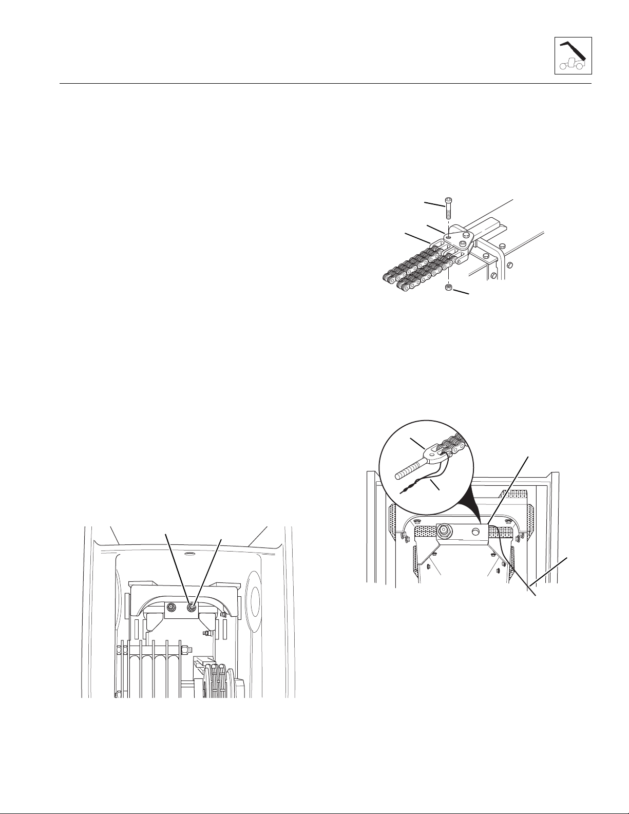
Boom
e. Chain Replacement
IMPORTANT: Chains and clevis’ are wear items and
experience the same stress. DO NOT attempt to service or
repair a chain or clevis. Replacement chains are shipped
pre-assembled with new clevis’.
Extend Chain Removal
1. Park the vehicle on a hard, level surface.
2. Fully retract the boom and raise the boom to a
horizontal position. Place the travel select lever in
(N) NEUTRAL, move the neutral lock lever to
NEUTRAL LOCK position, engage the parking brake
switch and shut the engine OFF.
3. Remove the thumbscrew (Fig. 3 -110, 4), lockwasher
(5) and flat washer (6) holding the rear cover (1) to
the rear of the outer boom. Lift the rear cover straight
up until the capscrew in the top of the cover clears
the retaining hole in the top of the outer boom.
Remove the cover from the outer boom.
4. At the rear of the boom, locate the extend chain
elastic locknuts. Record the amount of threads
extending beyond both of the elastic locknuts
(Fig. 3-111, 1). These measurements will be the
starting point for adjustment of the extend chains
after installation.
6. At the front of the outer boom, remove the hex-socket
head capscrew (Fig. 3 -112, 1) and elastic locknut
(2) holding the right side extend chain clevis (3) to
the yoke plates (4). Discard the elastic locknut.
7. Inspect the hex-socket head capscrew (Fig. 3-112, 1)
for signs of wear or damage. Replace with a new
hex-socket head capscrew if damaged or worn.
1
4
3
2
Figure 3- 112 Remove the Extend Chain Clevis
from the Outer Boom
SH1810
8. At the rear of the boom, attach one end of a wire
(Fig. 3-113, 1) to the threaded clevis (2) on the right
side extend chain. Loop the wire around and twist
together to form a loop. Route the wire around the
right side of the clevis anchor plate (3).
Note: Remove and replace the extend chains one at a
time.
5. Remove the right side elastic locknut (Fig. 3 -111, 1)
and flat washer (2) holding the right side extend
chain clevis to the anchor plate on the inner boom.
Save the flat washer and discard the elastic locknut.
2
Figure 3- 111 Remove the Extend Chain Locknuts
1
MA6620
2
3
1
1
MA7990
Figure 3- 113 Wire Loop on Threaded Clevis
9. Have a second person assist with the removal of the
extend chain. One person should pull the chain from
the front of the boom while the second person guides
the wire into the boom from the rear. Remove the
wire from the clevis, but not from inside the boom.
Model 6036 Legacy
3.51

Boom
10. Inspect wear and condition of the booms, chains,
clevis’, chain sheaves, extend/retract cylinder, chain
rods, clevis anchors and all mounting hardware.
Replace any worn or damaged parts. DO NOT
attempt to make any repairs to the chain.
IMPORTANT: Chains and clevis’ are wear items and
experience the same stress. DO NOT attempt to service
or repair a chain or clevis. Replacement chains are
shipped pre-assembled with new clevis’.
Extend Chain Installation
1. Coat the threads of the threaded clevis (Fig. 3-114, 1)
with multi-purpose grease.
2. Lay the new extend chain (Fig. 3- 114, 2) on top of
the outer boom (3) with the threaded clevis (1)
toward the front of the boom.
3. Attach the wire (Fig. 3-114, 4) to the threaded clevis
(1) of the new extend chain. Loop the wire through
the clevis and twist together to form a loop.
4. Pull the extend chain forward and place over the
right side of the chain sheave (Fig. 3-114, 5). Guide
the wire and the threaded clevis into the boom by
placing the threaded clevis under the chain sheave
and in between the top of the inner boom (6) and the
intermediate boom (7).
6. Place the 3/4" flat washer (Fig. 3- 115, 4) onto the
threaded end of the threaded clevis and install a new
3/4-16 elastic locknut (5). Thread the elastic locknut
onto the threaded clevis until the threads are flush
with the top of the nut.
3
2
1
4
5
1
MA8000
Figure 3- 115 Connect the Threaded Clevis
to the Anchor Plate
3
1
2
5
6
4
~
~
~
7
Figure 3- 114 Extend Chain Reassembly
5. While one person guides the extend chain into the
front of the boom, a second person should pull the
wire (Fig. 3-115, 1) and threaded clevis toward the
rear of the boom. Guide the threaded clevis (2) into
the hole in the anchor plate (3).
3
MA7000
7. Pull the anchor clevis (Fig. 3 -116, 1) up around the
double chain sheave and position the clevis between
the yoke plates (2).
8. Coat the hex-socket head capscrew (Fig. 3 -116, 3)
with anti-seize compound. Insert the capscrew
through the yoke plates and clevis, and secure in
place with a new 3/8-16 elastic locknut (4). Tighten
securely, but ensure that the chain clevis pivots
freely.
3
2
1
4
Figure 3- 116 Extend Chain Clevis and Yoke Plates
SH1810
9. Cut the loop in the wire and remove the wire from the
clevis.
3.52
Model 6036 Legacy

Boom
10. Repeat the entire “Extend Chain Removal and
Installation” section. Starting with Step 4 of the
“Extend Chain Removal” and continuing on to Step 9
of the “Extend Chain Installation,” to remove and
replace the left side extend chain.
11. At the rear of the boom, tighten the two elastic
locknuts (Fig. 3-117, 1) on the extend chain clevis’
until the amount of threads protruding beyond each
elastic locknut is the same as the measurement
recorded during removal of the extend chains.
1
13. Install the rear cover (Fig. 3 -118, 1), by inserting the
capscrew (2) at the top of the cover into the hole (3)
in the top of the boom. Secure the rear cover using
one thumbscrew (4), one internal-tooth lockwasher (5)
and one flat washer (6).
2
1
3
MA6620
Figure 3- 117 Extend Chain Adjustment Locknuts
12. Check and adjust the extend chain tension. (Refer to
Section 3.3.7, c. “Boom Chain Tension Check.”)
6
5
4
Figure 3- 118 Install the Rear Cover on the Outer Boom
MA6420
Model 6036 Legacy
3.53

Boom
Retract Chain Removal
1. Park the vehicle on a hard, level surface.
2. Fully retract the boom and raise the boom to a
horizontal position. Place the travel select lever in
(N) NEUTRAL, move the neutral lock lever to
NEUTRAL LOCK position, engage the parking brake
switch and shut the vehicle OFF.
3. Remove the thumbscrew (Fig. 3- 119, 1), lockwasher
(2) and flat washer (3) holding the rear cover (4) to
the rear of the outer boom. Lift the rear cover straight
up until the capscrew in the top of the cover clears
the retaining hole in the top of the outer boom.
Remove the cover from the outer boom.
3
2
Figure 3- 120 Install the Retract Chain Locknut
1
MH1110
Note: Record the location of the shoulder bolt
4
(Fig. 3-121, 1) to ensure correct installation.
6. At the rear of the boom, locate the two retract chain
anchor plates (Fig. 3- 121, 2) holding the retract
chain to the inner boom, just in front of the retract
chain sheave. Remove the elastic locknut (3) and
shoulder bolt (1) holding the retract chain clevis (4)
to the anchor plates. Discard the elastic locknut and
save the shoulder bolt. The two anchor plates can
remain in place on the inner boom.
3
2
1
Figure 3- 119 Remove the Boom Rear Cover
MA6420
4. At the front underside of the outer boom, record the
amount of threads extending beyond the elastic
locknut (Fig. 3-120, 1). This measurement will be
the starting point for adjustment of the boom retract
chain.
5. Remove the elastic locknut (Fig. 3 -120, 1) and flat
washer (2) holding the retract chain threaded clevis
(3) to the mounting tab. Save the flat washer and
discard the elastic locknut.
1
4
2
3
MA8010
Figure 3 -121 Retract Chain Anchor Plates
7. From the rear of the boom, pull the retract chain out
of the rear of the boom.
3.54
Model 6036 Legacy

8. Inspect wear and condition of the booms, chains,
clevis’, chain sheaves, extend/retract cylinder, chain
rods, clevis anchors and all mounting hardware.
Replace any worn or damaged parts. DO NOT
attempt to make any repairs to the chain.
Note: Chains and clevis’ are wear items and experience
the same stress. DO NOT attempt to service or repair a
chain or clevis. Always replace a stretched or damaged
chain or clevis with a new part. Replacement chains are
shipped pre-assembled with new clevis’.
Retract Chain Installation
Boom
1
3
4
2
1. Coat the threads of the threaded clevis (Fig. 3-122, 1)
with multi-purpose grease.
Note: Have a second person help with the installation of
the new retract chain in between intermediate and outer
boom assemblies.
2. From the rear of the boom, one person should push
the threaded clevis end (Fig. 3- 122, 1) of the new
retract chain under the chain sheave and down
between the intermediate boom and the outer boom.
Keeping the retract chain (2) to the right side of the
boom, push the threaded clevis down to the tab (3)
at the front underside of the outer boom.
3. The person at the front of the boom should guide the
threaded end of the clevis (Fig. 3 -122, 1) through
the hole in the tab using a Phillips screwdriver (4).
Insert the screwdriver through the hole in the tab and
catch the countersunk hole in the end of the clevis.
Guide the threaded clevis out as the person at the
rear of the boom pushes the retract chain.
Note: ALWAYS use new elastic-lined nuts to help
ensure proper fastening.
4. Install the flat washer (Fig. 3-122, 5) and a new 3/4-16
elastic locknut (6) onto the threaded clevis. Tighten
the locknut until the threaded end of the clevis is
flush with the top of the locknut.
6
5
Figure 3- 122 Retract Chain Clevis to Tab in Outer Boom
MH2560
5. At the rear of the boom, place the retract chain up
and over the chain sheave. Place the clevis
(Fig. 3-121, 4) between the two anchor plates (1).
Align the hole in the clevis (4) with the second hole
from the rear of the anchor plates.
6. Insert the shoulder bolt (Fig. 3-121, 3) through the
plates and clevis, and secure in place with a new 3/8-16
elastic locknut (2). Tighten the locknut securely.
7. At the front underside of the outer boom, tighten the
elastic locknut (Fig. 3- 123, 1) on the retract chain
clevis until the amount of threads protruding beyond
the elastic locknut is the same as the measurement
recorded during removal of the retract chain.
1
Model 6036 Legacy
OA0512
Figure 3- 123 Retract Chain Adjustment Locknut
3.55

Boom
8. Check and adjust the retract chain tension. (Refer to
Section 3.3.7, c. “Boom Chain Tension Check.”)
9. Install the rear cover (Fig. 3 -124, 1) by inserting the
capscrew (2) at the top of the cover into the hole (3)
in the top of the boom. Secure the rear cover using
one thumbscrew (4), one internal-tooth lockwasher (5)
and one flat washer (6).
2
1
3
Wear Pad Gaps:
FRONT, outer boom to intermediate boom, and
intermediate boom to inner boom:
TOP:............................. .07-.13" (1,8-3,3 mm), minimum
SIDE:............................ .07-.13" (1,8-3,3 mm), minimum
Note: Shim front, upper and side wear pads to maintain
a minimum gap in both vertical and horizontal directions.
REAR, intermediate boom to outer boom, and inner
boom to intermediate boom:
UPPER PADS: Shim upper rear wear pads to maintain a
maximum gap of .06" (1,7 mm) at the rear edge of the upper
pads, and to maintain a total minimum gap of .07-.13"
(1,8-3,3 mm) in the vertical direction.
a. Boom Wear Pad Replacement
When installing a wear pad on one surface of a boom,
replace the wear pad on the opposite surface. Usually,
shimming will remain the same when installing new wear
pads. When installing new wear pads, apply Loctite
®
#242 (blue) to all wear pad mounting capscrews and
torque to 31 lb/ft (42 Nm).
6
5
4
Figure 3- 124 Install the Rear Cover on the Outer Boom
MA6420
3.3.8 Boom Wear Pads
Flat rectangular wear pads with metal inserts are used. The
inserts are special metal hardware that will scratch the
boom if the wear pads are worn beyond usable limits.
(Refer to the Model 6036 Legacy Owners/Operators
Manual.)
A total of 30 wear pads are installed on the outer,
intermediate and inner booms. Seven wear pads are
attached to the inner boom, 15 to the intermediate boom,
and eight to the outer boom.
At the front of the boom, shims are used to maintain a
minimum gap of .07-.13" (1,8-3,3 mm) between the wear
pads and the booms.
Inner Boom
All inner boom pads are mounted on the rear outside of
the inner boom (Fig. 3- 125, 1). The inner boom must be
removed from the vehicle in order to replace the wear
pads. Refer to Section 3.3.1, “Inner Boom Removal,” for
information on removing the inner boom.
1
1
1
3.56
1
Figure 3- 125 Inner Boom Wear Pad Locations
Model 6036 Legacy
MA8030

Boom
Use shims (Fig. 3-126, 1) under the upper rear wear pads
as required to maintain a maximum gap of .06" (1,7 mm)
(2) at the rear edge of the pads and maintain a total
minimum gap of .07-.13" (1,8-3,3 mm) in the vertical
direction.
Use shims as required to maintain a total minimum gap of
.07-.13" (1,8-3,3 mm) between the side wear pads and
boom surfaces.
34
2
1
MS06302
Figure 3- 126 Inner Boom (3) and Intermediate Boom (4),
Upper Rear Wear Pad Gap Dimensions
Intermediate Boom
1
1
Figure 3- 127 Intermediate Boom Rear
Wear Pad Locations
1
1
MA8030
The inner boom must be removed from the vehicle to
allow removal of the rear wear pads on the rear top and
rear sides of the intermediate boom, and the wear pads
on the rear bottom of the intermediate boom. Refer to
Section 3.3.1, “Inner Boom Removal,” for information on
removing the inner boom.
Coat all wear pad capscrews with Loctite 242
before installation. DO NOT allow Loctite
®
®
(blue)
to come into con-
tact with wear pads.
The wear pads (Fig. 3- 127, 1 and Fig. 3 -128, 1) on the
front of the intermediate boom can be replaced by
removing the fasteners securing them to the top, sides
and bottom of the boom.
When removing pads, move the boom sections as needed
to gain access for removal and installation of wear pads.
Mark or otherwise label each pad, spacer/shim and
hardware set for ease of installation later. Top wear pads
are secured to the boom with washers and capscrews;
side wear pads are secured with washers and capscrews.
Use Loctite
NOT allow Loctite
®
242 (blue) on all wear pad capscrews. DO
®
to come into contact with wear pads.
1
1
1
Figure 3- 128 Intermediate Boom Front
Wear Pad Locations
1
MA8020
Model 6036 Legacy
3.57

Boom
Use shims (Fig. 3 -129, 1) under the upper rear wear pads
as required, to maintain a maximum gap of .06" (1,7 mm)
(2) at the rear edge of the pads and maintain a total
minimum gap of .07-.13" (1,8-3,3 mm) in the vertical
direction.
Use shims as required to maintain a total minimum gap of
.07-.13" (1,8-3,3 mm) between the side wear pads and
boom surfaces.
34
2
1
MS06302
Figure 3- 129 Inner Boom (3) and Intermediate Boom (4),
Upper Rear Wear Pad Gap Dimensions
Outer Boom
1
1
1
Figure 3- 130 Outer Boom Wear Pad Locations
1
1
MA8020
All outer boom pads (Fig. 3- 130, 1) are mounted on the
front of the outer boom. Remove the top wear pads
before removing the bottom wear pads. Lower the
gooseneck to the ground until the intermediate boom
raises up, providing clearance for removing the bottom
pads. Fill the grease pockets (Fig. 3-131, 1) of the top
rear boom wear pads with multi-purpose grease. Use
®
Loctite
242 (blue) on all wear pad capscrews.
Use shims as required to achieve a total minimum gap of
.07-.13" (1,8-3,3 mm) between top and side wear pads
and boom surfaces.
MS0610
Figure 3 -131 Fill the Wear Pad Grease Pockets
with Multi-Purpose Grease
b. Boom Wear Pad Lubrication
The boom has been factory lubricated for proper wear pad
break-in and will normally not require further lubrication.
However, after replacing any wear pad(s), or after
prolonged periods of inoperation, light lubrication of the
boom wear surfaces with a rust inhibitor/lubricant such as
LPS 3, or equivalent is recommended to keep the boom
wear surfaces lubricated properly. Light lubrication of the
boom wear surfaces is also recommended in salt air
climates, and when the vehicle is stored, to help prevent
rusting.
3.58
Model 6036 Legacy

Boom
3.4 QUICK ATTACH ASSEMBLY
This vehicle is equipped with a quick attach system for
easy attachment changes.
3.4.1 Disconnecting from an Attachment
1. Park the vehicle on a hard, level surface.
2. Ground the attachment, place the travel select lever
in the (N) NEUTRAL position, place the neutral lock
lever in the (N) NEUTRAL LOCK position and
engage the parking brake switch.
3. Extend the boom approximately 10 ft (3,05 m) and
tilt the carriage backward. Shut the engine OFF.
4. Exit the vehicle using both hand holds.
Note: If removing a standard carriage with forks, spread
the forks apart on the carriage shaft. This will help give
the carriage better support to stand alone.
5. Raise the quick attach pin lock lever (Fig. 3-132, 1) and
pull out the lock pin (2) at the bottom of the quick attach.
1
2
7. Lower and then retract the boom until the
attachment pivot pins have disconnected from the
attachment.
3.4.2 Connecting to an Attachment
1. Perform this procedure on a level surface only.
Position the vehicle directly behind the attachment to
be mounted.
2. Tilt the quick attach backward.
3. Extend the boom approximately 10 ft (3,05 m), and drive
the vehicle forward until the attachment pivot pins are
below and between the two hooks on the attachment.
4. Raise the boom until the attachment pivot pins have
seated fully in the hooks on the attachment.
5. Tilt the attachment up slightly. The quick attach link
should be tight up against the rear of the attachment,
and the holes in the link and the attachment should
be aligned.
6. Place the travel select lever in the (N) NEUTRAL
position, place the neutral lock lever in the (N)
NEUTRAL LOCK position, engage the parking brake
switch, unbuckle the seat belt and exit the vehicle
using both hand holds.
7. Lift the quick attach lever. Insert the quick attach pin
completely through the attachment and the quick
attach link. Be sure that the quick attach lock lever
has lowered and seated itself into the groove in the
quick attach pin.
OS03312
Figure 3- 132 Raise the Quick Attach Pin Lock Lever and
Pull Out the Lock Pin at the Bottom of the Quick Attach
6. Return to the operator’s compartment, fasten the seat
belt and lower the attachment to the ground in a level
position. Tilt the attachment forward; this will rotate
the quick attach link back away from the attachment.
Model 6036 Legacy
WARNING: DO NOT operate the vehicle
unless you are in the operator’s seat with the
seat belt fastened around you. Death or serious
injury could result if the seat belt is not
securely fastened.
8. Return to the cab, fasten the seat belt and resume
operation.
3.59

Boom
3.4.3 Quick Attach Removal
1. Remove the elastic locknut (Fig. 3 -133, 1) and
capscrew (2) holding the attachment tilt cylinder rod
end pin (3) to the quick attach assembly (4). Save
the capscrew and discard the elastic locknut.
2. Support the rod end (Fig. 3-133, 5) of the
attachment tilt cylinder. Use a brass punch and
rawhide hammer to remove the pin (3) from the quick
attach assembly.
3. Inspect the pin (Fig. 3- 133, 3) for nicks or surface
corrosion. Use fine emery cloth to repair minor nicks
or corrosion. If damaged and cannot be repaired, the
pin must be replaced.
6
5
2
3
4
5
6
Figure 3 -134 Remove the Quick Attach Pivot Pin
1
MA6440
4
2
~
1
5
Figure 3- 133 Remove Attachment Tilt
Cylinder Rod End Pin
4. Remove the elastic locknut (Fig. 3 -134, 1) and
capscrew (2) holding the quick attach pivot pin (3) to
the quick attach assembly (4). Save the capscrew
and discard the elastic locknut. Place a support
under the quick attach assembly to prevent it from
dropping when the pivot pin is removed.
5. Use a brass punch and rawhide hammer to remove
the quick attach pivot pin (Fig. 3-134, 3) from the
quick attach assembly and the bushings in the
gooseneck. Record the location and quantity of the
shim washers (5 and 6) as the pin is being removed.
Save the washers (5 and 6) from each side of the
quick attach.
6. Inspect the pin (Fig. 3- 134, 3) for nicks or surface
corrosion. Use fine emery cloth to repair minor nicks
or corrosion. If damaged and cannot be repaired, the
pin must be replaced.
3
MA6430
3.4.4 Quick Attach Installation
1. Align the quick attach (Fig. 3- 134, 4) between the
mounts on the gooseneck. Assemble a washer (6)
on each side of the quick attach. Reassemble the
shims (5) between the quick attach and the gooseneck.
DO NOT put all the shims on one side. The quick
attach should be centered in the gooseneck.
Note: ALWAYS replace elastic-lined nuts with new
elastic-lined nuts to help ensure proper fastening.
2. Coat the quick attach pivot pin (Fig. 3- 134, 3) with
an anti-seize compound. Insert the quick attach pivot
pin through the gooseneck, washers, shims and
quick attach. Use a tapered punch to line up the hole
in the pivot pin with the hole in the quick attach.
Insert the 5/8-11 x 5" capscrew (2) through the quick
attach and pin. Secure the capscrew in place with a
new 5/8-11 elastic locknut (1). Tighten securely.
3. Coat the rod end pivot pin (Fig. 3- 133, 3) with an
anti-seize compound. Swing the rod end (5) of the
attachment tilt cylinder up and align the rod end with
the mounting holes in the quick attach (4).
4. Insert the rod end pivot pin (Fig. 3-133, 3) through
the aligned holes. Use a tapered punch to align the
capscrew hole in the pivot pin and the mounting hole
in the quick attach hub. Insert the 1/2-13 x 5"
capscrew (2) through the quick attach hub from the
backside and secure in place with a new 1/2-13
elastic locknut (1). Tighten securely.
3.60
Model 6036 Legacy
 Loading...