


OWNERS/OPERATORS
MANUAL
Model 10042
(S/N 19031 thru 19971
and S/N 0160002407 thru 0160029583)
OH1562
Keep this manual with the vehicle at all times.
Printed in U.S.A. 2/07
8990501 C

WARNING: Improper operation of this vehicle can
cause injury or death. Only trained and authorized operators
should operate this vehicle.
Before starting the engine, do the following:
1. Read this owner/operators manual.
2. Read all the safety decals on the vehicle.
3. Clear the area of other persons.
Learn and practice safe use of vehicle controls in a safe,
clear area before you operate this vehicle on a worksite.
It is your responsibility to observe applicable laws and
regulations and to follow manufacturer's instructions on
vehicle operation and maintenance.
CALIFORNIA
Proposition 65 Warning
Diesel Engine exhaust and some of its constituents
are known to the State of California to cause
cancer, birth defects and other reproductive harm.
CALIFORNIA
Proposition 65 Warning
Battery posts, terminals and related accessories
contain lead and lead compounds, chemicals
known to the State of California to cause cancer
and birth defects or other reproductive harm.
Wash hands after handling
.

Table of Contents
Introduction
The Manual....................................2
Replacement Parts........................2
Reports..........................................2
Safety Practices
Disclaimer......................................3
Hazard Classification System........3
Accident Prevention Tags..............5
New or Additional Operators .........5
Instructional Symbols ....................6
Hazard Symbols ............................7
Avoidance Symbols.......................8
Avoidance Symbols (cont’d)..........9
Personal Considerations .............10
Operational Considerations.........14
Equipment Considerations ..........21
Operation
Operator Controls........................24
Instruments and Indicators..........37
Optional Controls.........................47
Pre-Operation Inspection.............57
Normal Starting............................58
Cold Starting................................59
Jump Starting ..............................60
Refueling .....................................61
Stabil-TRAK System....................63
Operating.....................................66
Using The Capacity Chart ...........74
Fork Ratings ................................87
How To Pick, Carry & Place A
Load..........................................88
Elevating Personnel.....................88
Using Other Attachments ............93
Shut-Off .......................................94
Emergency Operations
Towing A Disabled Vehicle..........95
Emergency Boom Lowering ........97
General Maintenance
General Maintenance................110
Maintenance Schedule And
Checklist.................................111
1. Lubrication Points..............116
2. Air Cleaner & Restriction
Indicator.............................118
3. Engine Cooling System .....122
4. Engine Oil And Filter.........125
5. Engine Fuel System..........129
6. Engine Fan Belt.................134
7. Hydraulic Oil and Filter......135
8. Transmission Oil and
Filter ..................................139
9. Axle Oil..............................142
10. Brake Disk Inspection .......144
11. Wheel End Oil ...................148
12. Wheels and Tires ..............150
13. Batteries............................152
14. Fuse and Relay
Replacement.....................154
15. Boom Chains and Wear
Pads..................................158
Storage and Transport ..............173
Storage......................................173
Transport...................................174
Test Procedures
Stabil-TRAK System Test..........175
Parking Brake/Transmission
De-Clutch Test Procedures....179
Four Wheel Steer Indexing
Procedure...............................181
Specifications
Fluid & Lubrication Capacities...182
Tires ..........................................183
Weights .....................................183
Vehicle Dimensions...................184
Electrical System.......................185
Engine.......................................186
Index.............................................187
Accident Prevention Tags
ã 2003 JLG Industries, Inc.
1
Introduction
Introduction
The Manual
This Owners/Operators Manual provides the information you need to
properly operate and maintain this vehicle.
IMPORTANT! Before
and carefully so you will understand the safety instructions and the
operation of the controls and safety equipment. You must comply with all
Danger, Warning, and Caution notices. They are for your benefit.
All reference to the right side, left side, front, or rear are given from the
operator's seat looking in a forward direction.
JLG Industries, Inc. is hereinafter referred to as JLG.
you operate this vehicle, read this manual completely
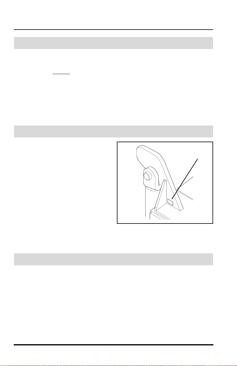
Replacement Parts
For easy reference when ordering
replacement parts or making service
inquiries on this vehicle, record its
model and serial number on the back
cover of this manual. The serial
number is stamped into the serial
number plate (1) which is located on
the vehicle’s frame.
IMPORTANT! The replacement of
any part on this vehicle by anything
other than a JLG authorized
replacement part may adversely
affect the performance, durability or
safety of this vehicle and may void the warranty. JLG assumes no liability
for unauthorized replacement parts which adversely affect the performance,
durability or safety of this vehicle.
1
OH0280
Reports
IMPORTANT! A Warranty Registration form must be filled out by the Sky
Trak Distributor, signed by the purchaser, and returned to JLG once the
product is sold and/or put into service. This report activates the warranty
period, assuring that your claims during the warranty period will be
processed promptly. To guarantee full warranty service, make sure your
local Sky Trak Distributor has returned the business reply card of this form
to JLG.
2
Model 10042 Rev. 11/03
Safety Practices
Safety Practices
Disclaimer
JLG reserves the right to make changes on and to add improvements upon
its products at any time without public notice or obligation. JLG also
reserves the right to discontinue manufacturing any product at its discretion
at any time.
NOTICE: Under OSHA rules, it is the responsibility of the employer to
provide operator training. Successful completion and certification of Safety
Training for Rough Terrain Forklifts is required. Operator Training Kits are
available by calling Ken Cook Company at (414) 466-6060. An order form
for these kits is available through our website,
http://www.jlg.com.
The information in this manual does not replace any safety rules and laws
used in your area. Before operating this vehicle, learn the rules and laws for
your area. Make sure the vehicle has the correct equipment according to
these rules and laws.
Your safety and the safety of others in the worksite depend significantly
upon your knowlege and understanding of all correct operating practices
and procedures for this vehicle.
WARNING: DO NOT modify or alter (weld, drill, etc.) any
part of this vehicle without consulting JLG. Modifications can
weaken the structure creating a hazard that can cause death or
serious personal injury.
Hazard Classification System
OP0330
This safety alert symbol is used with the following signal words to attract
your attention to messages found within the manual and on hazard decals
located on the vehicle. They are reproduced herein and pertain to proper
operation and procedure messages contained throughout the manual. The
message that follows the symbol contains important information about
Safety. To avoid possible death or serious personal injury, carefully read and
follow the messages! Be sure to fully understand the potential causes of
death or injury.
Model 10042 Rev. 11/03
3
Safety Practices
Signal Word
A signal word is a distinctive word located on hazard decals and used
throughout this manual that alerts the viewer to the existence of and relative
degree of the hazard.
DANGER:
The signal word “DANGER” indicates an imminently hazardous situation
which, if not avoided, will result in death or serious personal injury.
WARNING:
The signal word “WARNING” indicates a potentially hazardous situation
which, if not avoided, could result in death or serious personal injury.
CAUTION:
The signal word “CAUTION” indicates a potentially hazardous situation
which, if not avoided, may result in minor or moderate injury.
CAUTION:
The signal word “CAUTION”, used without the safety alert symbol, indicates
a potentially hazardous situation which, if not avoided, may result in
property damage.
For safe maintenance of the vehicle, read, understand and follow all
DANGER, WARNING and CAUTION information.
4
Model 10042 Rev. 11/03
Safety Practices
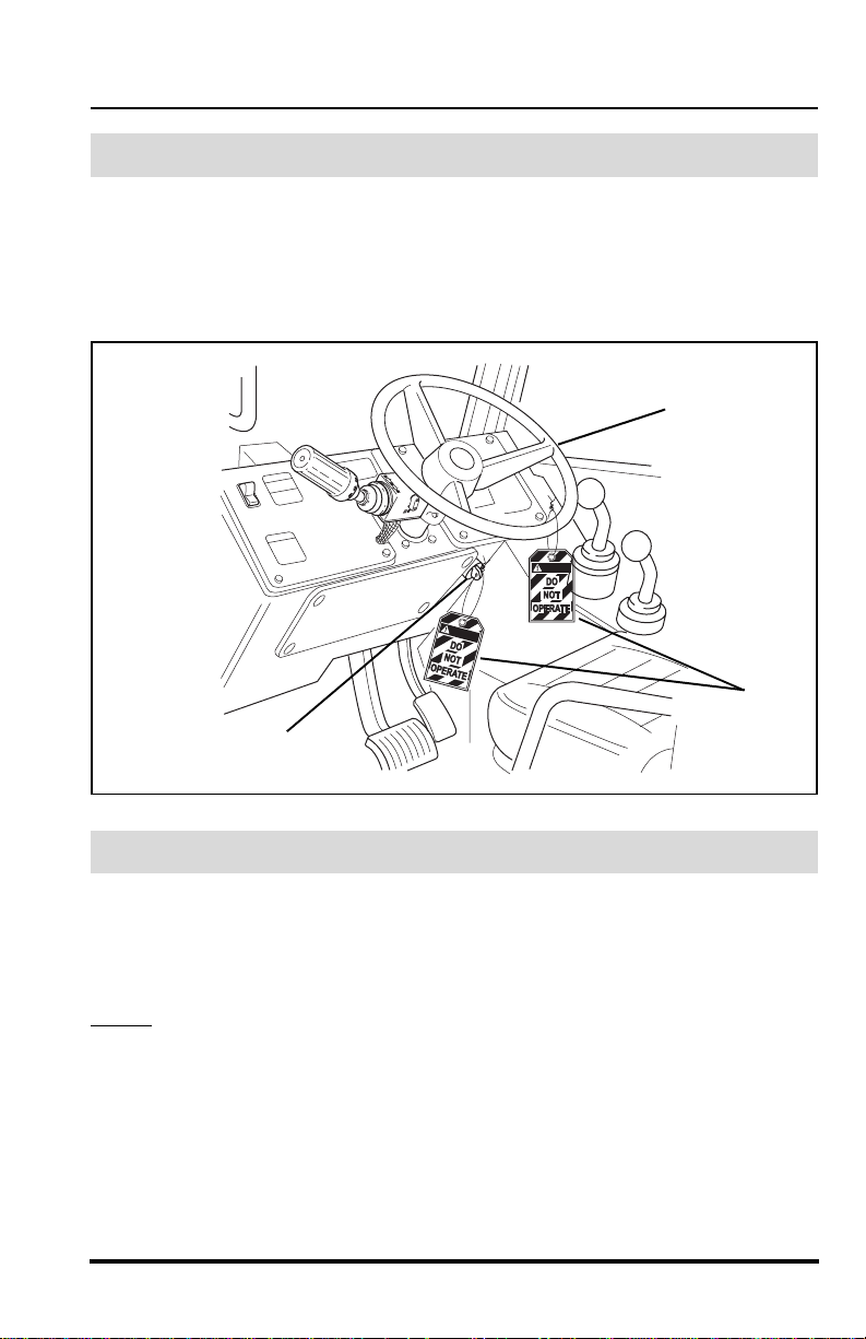
Accident Prevention Tags
Before beginning any maintenance or service, place an Accident Prevention
Tag (1) on both the starter key switch (2) and the steering wheel (3), stating
that the vehicle should not be operated. Actual Accident Prevention Tags,
which can be punched out and used, are included as the last page of this
manual. Retain these Accident Prevention Tags for reuse at a later date.
3
DANGER
DANGER
1
2
OH3350
New or Additional Operators
At the time of original purchase, the purchaser of this vehicle was instructed
by the seller on its proper use. If this vehicle is to be used by an employee or
is loaned or rented to someone other than the purchaser, make certain that
the new operator is trained, in accordance with the OSHA regulations
referenced on page 3, and reads and understands this Operators Manual
before
operating the vehicle.
In addition, make sure that the new operator has completed a walk-around
inspection of the vehicle, is familiar with all decals on the vehicle, and has
demonstrated the correct use of all controls.
Model 10042 Rev. 11/03
5
Safety Practices
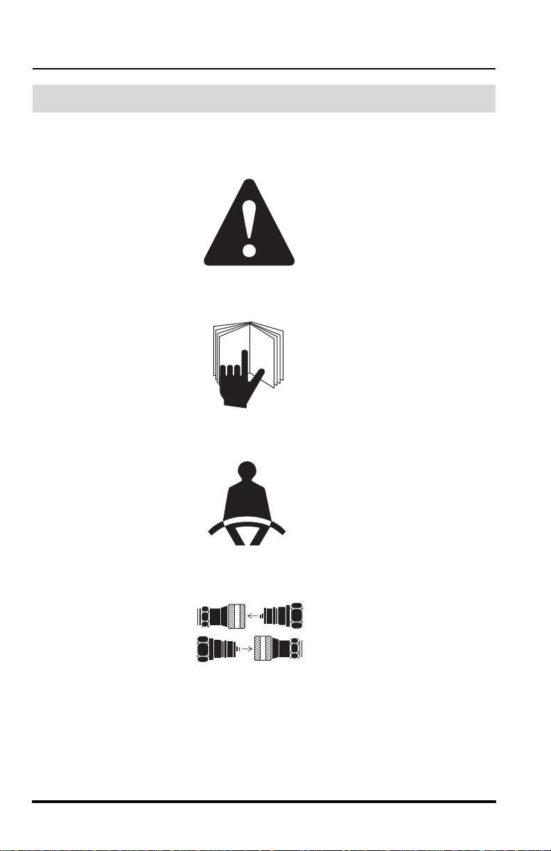
Instructional Symbols
The following symbol definitions will help you understand all hazard
related decals and load charts used on this vehicle.
OP0330
Safety Alert Symbol
OH2100
Read Operator’s Manual
OH2090
Fasten Seat Belt
OH3100
This Symbol Signifies That
Specific Attachments Must
Only Be Used On Vehicles
Equipped With Auxiliary
Hydraulics.
Always Connect Couplers.
6
Model 10042 Rev. 11/03
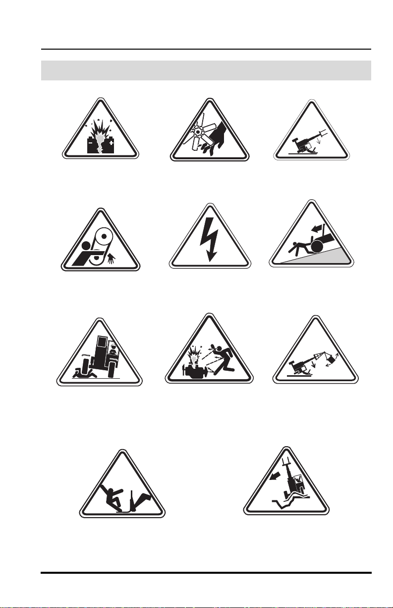
Hazard Symbols
Safety Practices
OH2110
-
Lead Acid Batteries
Generate Explosive
Gases
OH2300
Rotating Belts Can
Cut Or Entangle
OH3160
OH2120
Rotating Fan Blades
Can Cut
OH2150
Electrocution Can
Cause Death Or
Serious Injury
OU1450
OH2130
Vehicle Tipover Can
Crush
OH2140
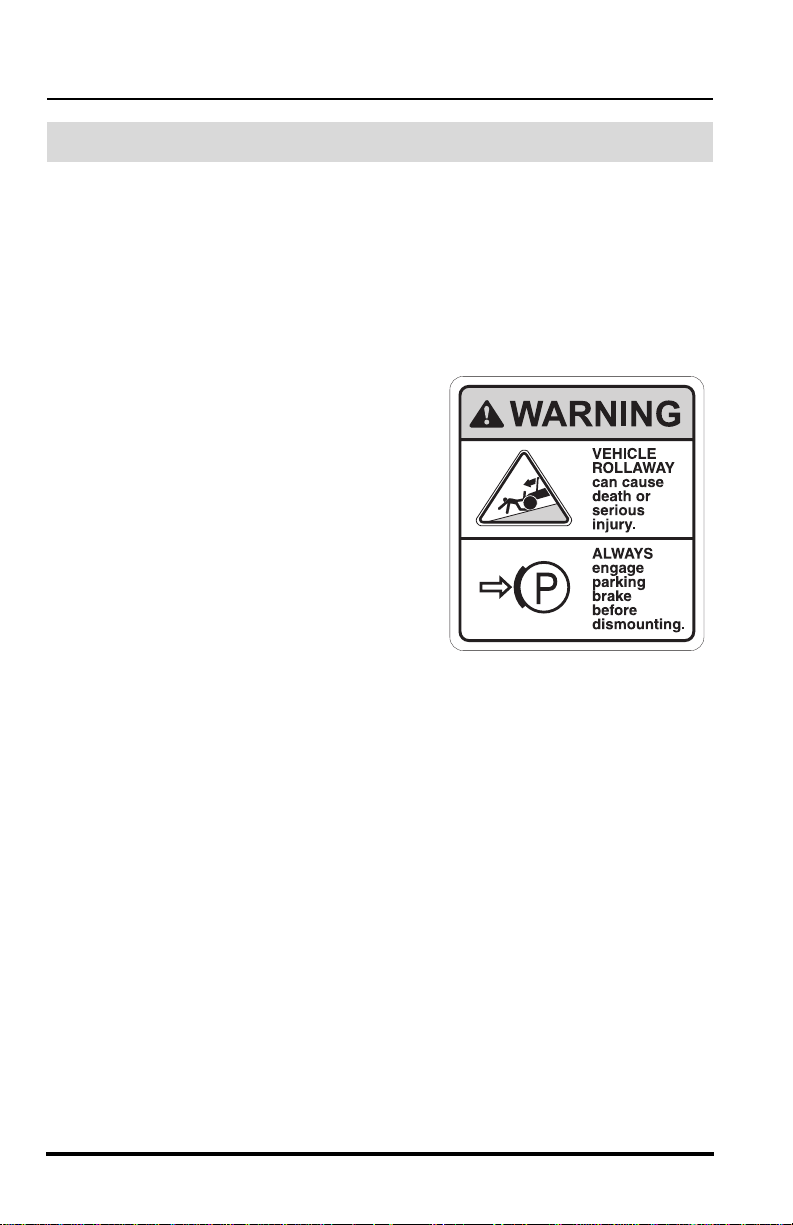
Vehicle Roll Away Can
Cause Death Or Serious
Injury
OH3110
AVOID CRUSHING,
Falling Off Vehicle Can
ENGINE EXPLOSION
Can Result In Death
Cause Death Or Serious
Injury
OH2161
FALLING OFF ATTACHMENT Can
Result In Death Or Serious Injury
Model 10042 Rev. 11/03
Or Serious Injury
VEHICLE TIPOVER, Outriggers
Over Holes Or Voids Can Cause
Death Or Serious Injury.
Swinging Loads Can
Cause Vehicle Tipover
Which Can Result In
Death Or Serious Injury
OH2721
7
Safety Practices
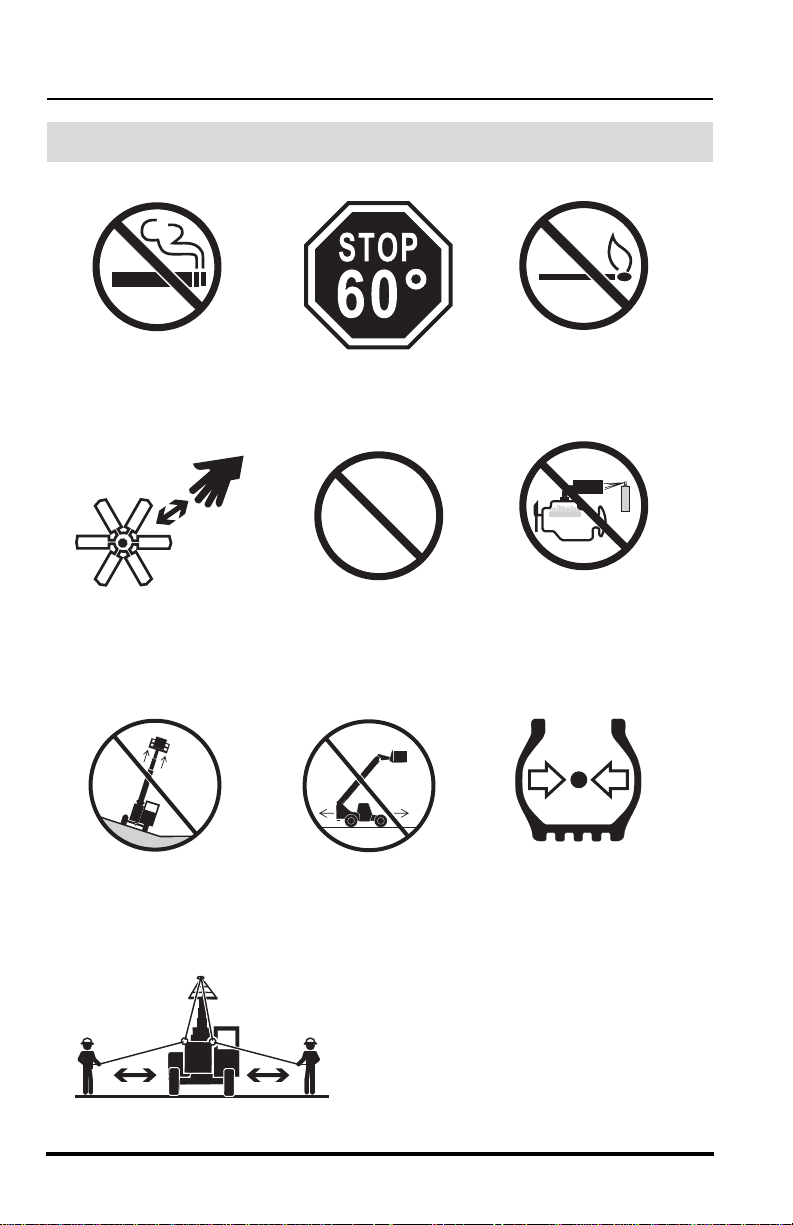
Avoidance Symbols
OH2320
Keep Lit Cigarettes
Away
OH2310
Keep Away From
Rotating Fan Blades
OH2280
Do Not Raise Boom
While On A Slope
OU1520
Stop Operation At
This Point
OU1510
Prohibition
Symbol. DO NOT
Operate
OH2270
Do Not Travel With
Boom Raised
OH2330
Keep Flames and
Ignition Sources Away
OU1460
DO NOT Use Ether Or
Other High Energy
Starting Aids.
Engine Equipped With
Grid Heating System.
OH2290
Maintain Proper Air
Pressure In Tire
To Avoid Vehicle Tipover
ALWAYS:
•Travel Slowly
• Rig Properly
• Use Two Tethers
OH3120
8
Model 10042 Rev. 11/03
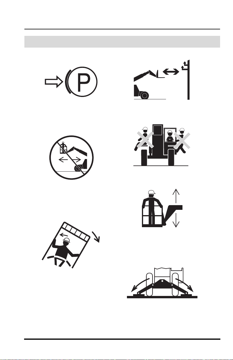
Safety Practices
Avoidance Symbols (cont’d)
Engage Parking Brake
Do Not Travel With
Personnel In Work
Platform
OH2260
OH2240
OH2250
Keep Clear Of Power
Lines
OH2230
Carry No Riders
OH2170
Use Only Compliant
Work Platforms To
Raise Or Lower
Personnel
DO NOT JUMP
• Brace Yourself and Stay
With Vehicle
• Keep Seat Belt Fastened
• Hold On Firmly
• Lean Away From The Point
Of Impact
Model 10042 Rev. 11/03
OH2220
OH3170
ALWAYS Fully Lower
Outriggers Onto Solid
Surfaces
9
Safety Practices
Personal Considerations
1. Seat Belt
Always fasten the seat belt before starting the engine.
2. Clothing and Safety Gear
DO NOT wear loose clothing or jewelry that can get caught on controls
or moving parts. Wear protective clothing and personal safety gear
issued or called for by job conditions.
3. Dismounting
DO NOT get off the vehicle until you:
• level the vehicle,
• ground the carriage,
• place the travel select lever in
(N) NEUTRAL,
• place the neutral lock lever in
(N) NEUTRAL LOCK,
• engage the parking brake
switch,
• turn the engine OFF, if
appropriate,
• unbuckle the seat belt,
OH1650
• exit the vehicle using the hand holds.
4. Chemical Hazards
A. Exhaust Fumes
Fumes from the engine exhaust can cause death or serious
personal injury. DO NOT operate vehicle in an enclosed area
without a ventilation system capable of routing the hazardous
fumes outdoors.
B. Explosive Fuel
Engine fuel is flammable and can cause a fire and/or an explosion.
Avoid danger by keeping sparks, open flames and smoking
materials away from the vehicle and from fuel during refueling or
when servicing the fuel system. Know where fire extinguishers are
kept on the worksite and how to use them.
10
Model 10042 Rev. 11/03
Safety Practices
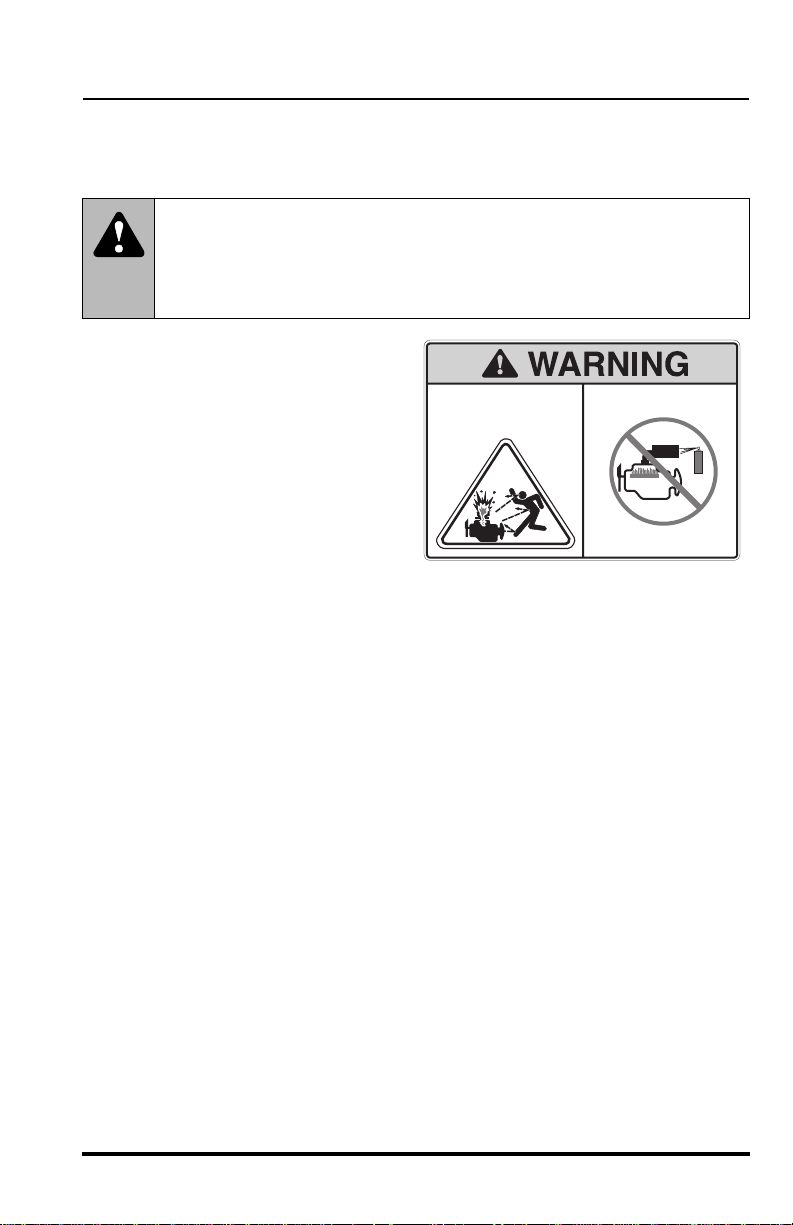
C. Ether or High Energy Starting Aids
The engine utilizes a grid heating system inside the induction
manifold for cold starting conditions.
WARNING: This diesel engine uses a grid heating system
inside the induction manifold. DO NOT use ether or any high
energy fuels to assist starting. An explosion may cause death or
serious personal injury or engine damage.
DO NOT use ether or any
other high energy starting
aids during cold starting. An
engine explosion can result
in death or serious personal
injury.
D. Hydraulic Fluid
DO NOT attempt to repair or tighten any hydraulic hoses or fittings
while the engine is running or when the hydraulic system is under
pressure. Fluid in the hydraulic system is under enough pressure
that it can penetrate the skin causing death or serious personal
injuries.
ENGINE EXPLOSION can
result in death or serious
personal injury.
DO NOT use Ether or other
high energy starting aids.
Engine equipped with
grid heating system.
4110460
OU1470
HOT HYDRAULIC FLUID WILL CAUSE SEVERE BURNS. Wait
for fluid to cool down before disconnecting lines.
DO NOT use your hand to check for leaks. Use a piece of
cardboard or paper to search for leaks. Wear gloves to protect
hands from spraying fluid.
Hydraulic fluid can cause permanent eye injury. Wear appropriate
eye protection and stop engine. Relieve pressure before
disconnecting lines by moving all joysticks back and forth through
all functions.
If anyone is injured by or if any hydraulic fluid is injected into the
skin, obtain medical attention immediately or gangrene may result.
Model 10042 Rev. 11/03
11
Safety Practices
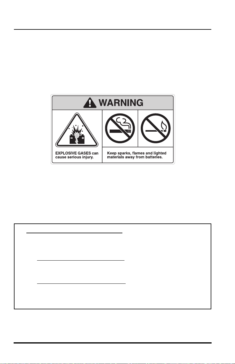
E. Batteries
The following WARNING is intended to supplement and does not
replace the warnings and information provided on the battery by the
battery manufacturer.
When jump starting the vehicle, carefully follow instructions found
under “Jump Starting” on page 60.
-
Keep sparks, flames and lit smoking materials away from the
battery at all times. Lead acid batteries generate explosive gases.
Severe chemical burns can result from improper handling of battery
electrolyte. Wear safety glasses and proper protective gear when
handling batteries to prevent electrolyte from coming in contact with
eyes, skin or clothing.
OS0621
Battery Electrolyte First Aid:
• External Contact — Flush with water.
• Eyes — Flush with water for at least 15 minutes and
get medical attention immediately
• Internal Contact — Drink large quantities of water. Follow
with Milk of Magnesia, beaten egg or vegetable oil.
Get medical attention immediately
IMPORTANT! In case of internal contact, DO NOT give fluids that
would induce vomiting!
12
.
.
Model 10042 Rev. 11/03
Safety Practices
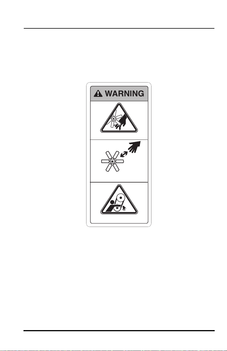
5. Moving Parts Hazard
DO NOT place limbs near moving parts. Severing of any body part can
result.
Turn OFF engine and wait until fan and belts stop moving before
servicing.
MOVING PARTS can cut.
Keep clear of fan and belts
while engine is running.
MOVING PARTS can entangle.
OT0810
6. Lowering Boom or Falling Load Hazard
DO NOT get under a raised boom unless it is blocked up safely. Always
empty the attachment of any load and block the boom up before doing
any servicing that would require the boom to be raised.
NEVER allow anyone to walk or stand under the boom. A lowering
boom or falling load can result in death or serious personal injury.
Model 10042 Rev. 11/03
13

Safety Practices
Operational Considerations
1. Preparation and Prevention
Know the location and function of all vehicle controls.
Make sure all persons are away from the vehicle and that the travel
select lever is in the (N) NEUTRAL position with the parking brake
switch engaged before starting the engine.
Holes, obstructions, debris and other worksite hazards can cause death
or serious personal injury. Always walk around and look for these and
other hazards before operating the vehicle in a new worksite.
Prevent accidents when you move the vehicle around the worksite.
Know the rules for movement of people and vehicles on the worksite.
Have a person act as a lookout for you. Follow the instructions of
signals and signs.
DO NOT operate the vehicle unless all hazard and instructional decals
are in place and readable. (Replace all missing, illegible, or damaged
decals.)
2. Clearances
Look out for and avoid other personnel, machinery and vehicles in the
area. Use a spotter if you do not have a clear view of conditions that
affect clearances. Travel with the boom fully retracted and lowered as
far as possible while still maintaining enough ground clearance for
conditions.
Always check boom clearances carefully before driving underneath
door openings, bridges, etc.
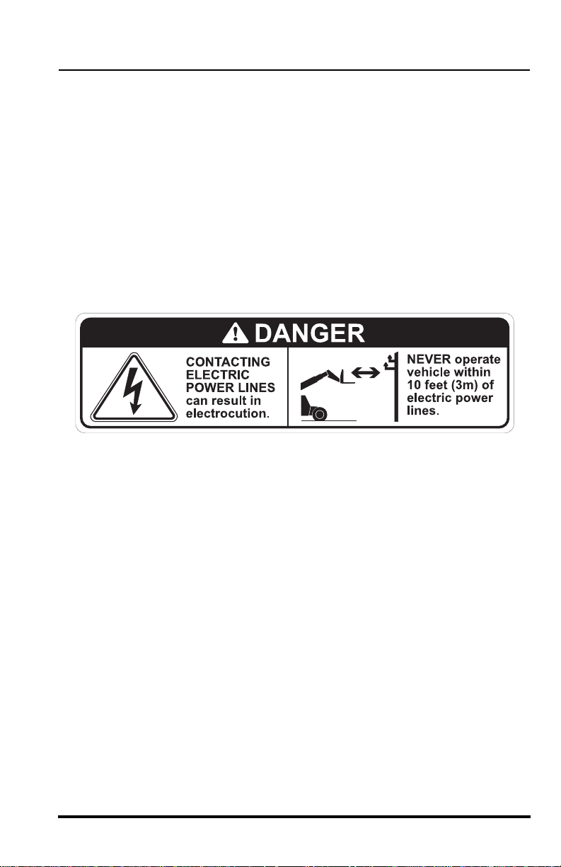
Always check for power lines when raising the boom. Beware of
overhead wires. Contact with electrical power lines can result in
electrocution. See “Electrocution Hazards” on page 15.
3. Visual Obstruction
Dust, smoke, fog, etc. can decrease vision and cause an accident.
Always stop or slow the vehicle until the obstruction clears and the
worksite is visible again. Have a lookout person assist you.
Where the load will obstruct the operator’s vision, it is recommended
that the vehicle be operated in REVERSE, looking backwards in the
direction of travel. Travel at a slower speed and get someone to direct
you.
14
Model 10042 Rev. 11/03
Safety Practices
4. Underground Hazards
Know the location of all underground hazards before operating this
vehicle in a new area or worksite. Electrical cables, gas and water
pipes, sewer, or other underground objects can cause death or serious
personal injury. Contact your local underground utility service or diggers
hotline to mark all underground hazards.
5. Electrocution Hazards
NEVER operate this vehicle in an area where overhead power lines,
overhead or underground cables, or other power sources may exist
without first requesting that the appropriate power or utility company deenergize the lines, or take other suitable precautions.
OS0063
Model 10042 Rev. 11/03
15
Safety Practices
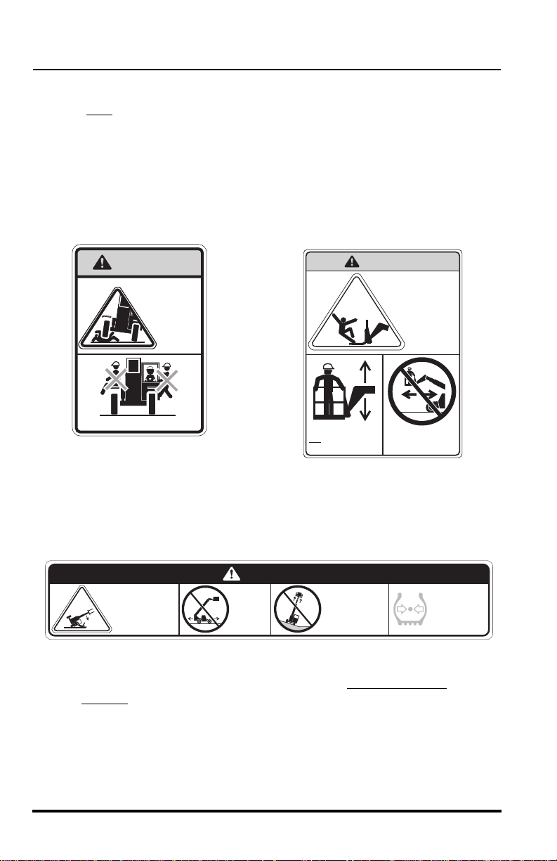
6. Elevating Personnel
Use only a compliant work platform meeting the ASME B56.6 standards
for lifting and lowering personnel. NEVER transport personnel in a work
platform for even the shortest distance.
Death or serious personal injury can occur if these rules are not
obeyed. Riders can fall and be crushed or run over. Avoid accidents.
For other specific precautions, see “Elevating Personnel” on page 88.
WARNING
AVOID
CRUSHING,
falling off
vehicle can
cause death
or serious
Allow no riders
injury
OH3180
Lift or lower personnel
only in a compliant
work platform.
WARNING
FALLING OFF ATTACHMENT,
can result in death or
serious injury.
DO NOT TRAVEL
with personnel in
a work platform.
OU0620
7. Tip Over Hazard
DANGER
VEHICLE
TIPOVER
can result
in death or
serious injury.
DO NOT
travel
with the
boom
raised.
Traveling with the boom raised is dangerous and can cause tipover.
Keep the boom as low as possible. Travel with extreme caution
the slowest
possible speed.
DO NOT raise
boom while
on a slope
unless load
is level.
4110389
MAINTAIN
proper tire
pressure at
all times.
OS0086
and at
Keep the vehicle under control at all times. When negotiating turns,
slow down and turn the steering wheel in a smooth sweeping motion.
Avoid jerky turns, starts or stops. Reduce vehicle speed on rough
ground and slopes.
16
Model 10042 Rev. 11/03
Safety Practices
DO NOT exceed the rated lift capacity of the vehicle as structural
damage and unstable conditions will result.
To ensure that the vehicle is positioned in the most stable condition
before operating an attachment, use the frame sway control (frame tilt)
to level the vehicle. The vehicle is level when the frame level indicator
gauge reaches (0°) zero degrees.
If the vehicle cannot be leveled using the frame sway control, reposition
the vehicle.
Frame swaying left or right with the boom raised above horizontal is
dangerous. Always use the frame sway control to level the vehicle
before
raising the boom above horizontal, with or without a load. If the
vehicle cannot be leveled using frame sway control, reposition the
vehicle.
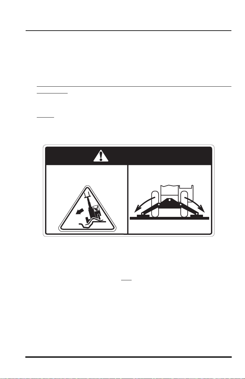
DANGER
VEHICLE TIPOVER, outriggers
over holes or voids can cause
death or serious injury.
Lowering outriggers over holes or on soft terrain can compromise the
stability of the vehicle which could result in vehicle tipover. For optimum
stability, lower the outriggers just far enough until the front of the vehicle
starts to raise and maintains a firm
NEVER attempt to move the vehicle after the outriggers have been
lowered.
ALWAYS fully lower outriggers
onto solid surfaces.
4107971
OH0801
footing.
Model 10042 Rev. 11/03
17
Safety Practices
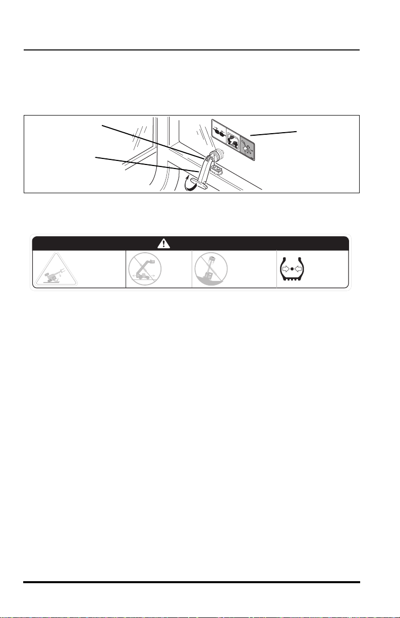
8. Emergency Exit Rear Window
The rear window (1) in the enclosed cab can be used as an emergency
exit by removing the latch pin (2) located on the window latch (3). The
window is then free to swing open.
2
3
1.
2.
3.
4
1
09
7
91
1
9. Tire Pressure
DANGER
VEHICLE
TIPOVER
can result
in death or
serious injury.
DO NOT
travel
with the
boom
raised.
MAINTAIN proper tire pressures at all times. An underpressurized
tire(s) adversely affects vehicle stability. If proper tire pressures are not
maintained, this vehicle can tip over.
To ensure proper vehicle stability, check all four tire pressures before
operating the vehicle.
DO NOT raise
boom while
on a slope
unless load
is level.
MAINTAIN
proper tire
pressure at
all times.
OH1730
OS0085
18
Model 10042 Rev. 11/03

Safety Practices
10.Do Not Jump
DANGER
AVOID CRUSHING
if vehicle tips.
Jumping can
result in death
or serious
injury.
DO NOT JUMP.
Brace yourself.
Stay in cab.
Keep seat belt on.
If a vehicle ever becomes unstable and starts to tip over:
• BRACE YOURSELF and STAY WITH THE VEHICLE,
• KEEP YOUR SEAT BELT FASTENED,
• HOLD ON FIRMLY and
• LEAN AWAY FROM THE POINT OF IMPACT.
Indecision and trying to escape from a tipping vehicle can result in
death or serious personal injury.
OH3190
Model 10042 Rev. 11/03
19

Safety Practices
11.Slopes
DO NOT park the vehicle on an incline and leave it unattended.
• Driving across a slope is dangerous, as unexpected changes in
the slope can cause tipover. Ascend or descend slopes slowly
and with caution
• Ascend or descend slopes with the heavy end of the vehicle
pointing up
NOTE: The rear of the vehicle is normally considered the heavy end unless
the carriage is fully loaded. In this case the front of the vehicle is now the
heavy end.
• Unloaded vehicles should be operated on all slopes with the
carriage pointing down
• On all slopes, the load must be tilted back and raised only as far
as necessary to clear the ground.
• When operating on a downhill slope, reduce travel speed and
downshift to a low gear to permit compression braking by the
engine and aid the application of the service brakes.
.
the slope.
the slope.
12.Falling Load Hazard
DO NOT exceed the total rated load capacity of the specific type fork
being used. Each fork is stamped with a maximum load capacity. If the
capacity is exceeded, forks may break. See “Fork Ratings” on page 87.
DO NOT downshift at a high ground speed. Sudden slowing can cause
the load to drop off the forks.
13.Ventilation
Sparks from the electrical system and the engine exhaust can cause an
explosion. DO NOT operate this vehicle in an area with flammable dust
or vapors unless good ventilation has removed the hazard.
Carbon monoxide fumes from the engine exhaust can cause suffocation
in an enclosed area. Good ventilation is very important when operating
this vehicle.
20
Model 10042 Rev. 11/03

Safety Practices
Equipment Considerations
WARNING: DO NOT modify or alter (weld, drill, etc.) any
part of this vehicle without first consulting JLG. Modifications can
weaken the structure creating a hazard that can cause death or
serious personal injury.
DO NOT by-pass or disconnect any electrical or hydraulic circuits.
Consult the JLG Service Department or your local Sky Trak Distributor
if any circuit is malfunctioning.
DO check for frayed or cut seat belt webbing, damaged buckles or loose
mounting brackets. Replace immediately if required.
ALWAYS wear a seat belt when operating the vehicle.
DO check tire pressure on all four tires. Add air if required.
DO check the condition of all four rims. Check for bent flanges and/or
bead mounting areas.
DO check the parking brake/transmission de-clutch operation. Refer to
the test procedures on page 179. Repair immediately if required.
DO keep all non-skid surfaces clean and free of debris. Replace if worn,
damaged or missing.
DO check the condition of decals. Replace decals if missing, damaged
or illegible. The following pages show the proper location of the decals.
Model 10042 Rev. 11/03
21
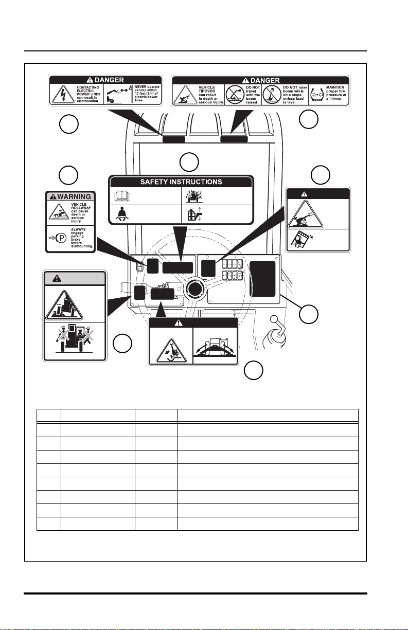
Safety Practices
3
7
2
WARNING
AVOID
CRUSHING,
falling off
vehicle can
cause death
or serious
injury
1. Read operator's manual
before operating.
2. Fasten seat belt.
VEHICLE TIPOVER, outriggers
over holes or voids can cause
death or serious injury.
3. Allow no riders.
4. Use a compliant
DANGER
ALWAYS fully lower outriggers
onto solid surfaces.
work platform to lift
or lower personnel.
1
Allow no riders
4107971
8
Item Part Number Quantity Decal Description
1
2 4110188 1 Vehicle Rollaway Warning
3 4108991 1 Electrocution Danger
4 7301677 1 Load Chart Booklet
5 4110137 1 Tipover danger
6 4110187 1 Do Not Jump Danger
7 4110188 1 Safety Instructions
8 4107971 1 Outrigger Over Holes Danger
4110188 1 No Riders Warning
5
6
DANGER
AVOID CRUSHING
if vehicle tips.
Jumping can
result in death
DO NOT JUMP.
Brace yourself.
Stay in cab.
Keep seat belt on.
4
OH2733
or serious
injury.
22
Model 10042 Rev. 11/03
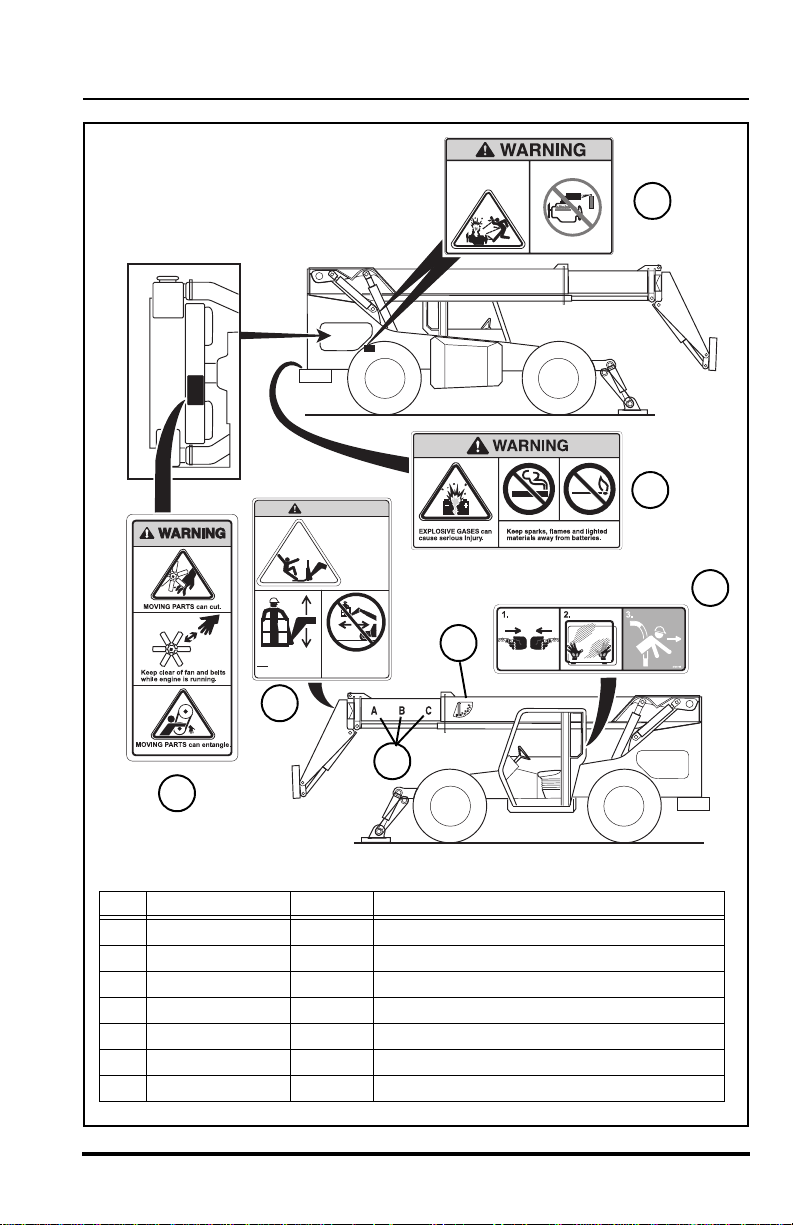
Safety Practices
Lift or lower personnel
only in a compliant
work platform.
11
WARNING
FALLING OFF ATTACHMENT,
can result in death or
serious injury.
DO NOT TRAVEL
with personnel in
a work platform.
ENGINE EXPLOSION can
result in death or serious
personal injury.
DO NOT use Ether or other
high energy starting aids.
15
Engine equipped with
grid heating system.
4110460
10
14
13
4110389
12
9
Item Part Number Quantity Decal Description
9
10 4110172 1 Explosive Gases Warning
11 4110389 1 Carrying Personnel Warning
12 4107442 1 Boom Extend Letters
13 4105262 1 Boom Angle Indicator
14 4109791 1 Emergency Exit (Enclosed Cab Only)
15 4110460 2 Ether Starting Warning
Model 10042 Rev. 11/03
4110184 2 Moving Parts Warning
OH1754
23
Operation
Operation
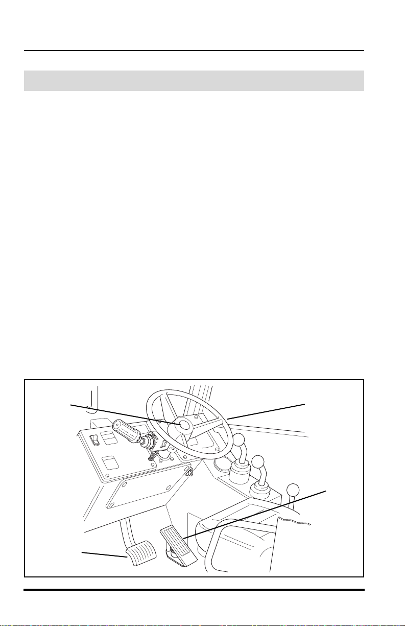
Operator Controls
Accelerator Pedal
Pressing down the accelerator pedal (1) increases engine and hydraulic
speed of the vehicle. The pedal is spring-loaded to return to idle speed.
NOTE: The accelerator pedal is also used to activate the Cummins ECM
Diagnostic system. With the ignition switch in the RUN position, depress
and release the pedal three times to activate the system.
Service Brake Pedal
Pressing down the brake pedal (2) decreases the speed of the vehicle by
applying the service brakes located in the axles. In the event of engine
power loss, the service brake pedal can also be used for braking. It also
activates and locks the rear axle to frame lock system when boom angles
are greater than 40°, as long as the pedal is depressed.
Steering Wheel
Turning the steering wheel (3) to the left or right steers the vehicle in the
corresponding direction. Any one of the steering modes are selectable.
Refer to “Steering Select Switch” on page 26.
Horn Button
Pressing the button (4) sounds the horn.
4
2
24
3
1
MA8560
Model 10042 Rev. 11/03
Operation
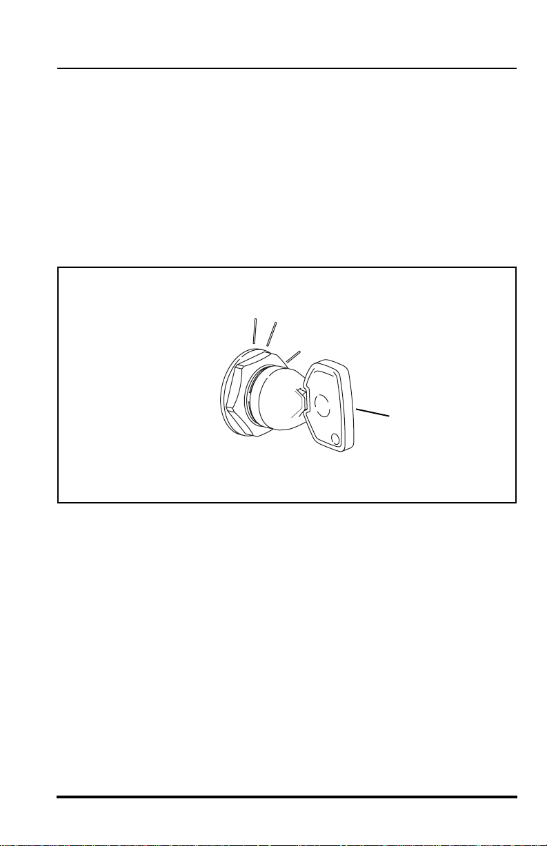
Ignition Switch
Using the ignition switch key (5), the switch may be turned clockwise from
the OFF (6) position to the RUN (7) and START (8) positions. The START
position is spring-loaded to return to the RUN position and must be
manually held in place for starting.
OFF position (6) — The entire electrical system is shut down.
RUN position (7) — All controls and indicators are operable.
START position (8) — Engages starter motor to crank the engine when the
parking brake switch is engaged and the transmission is in NEUTRAL.
6
7
8
5
Model 10042 Rev. 11/03
OT0680
25
Operation
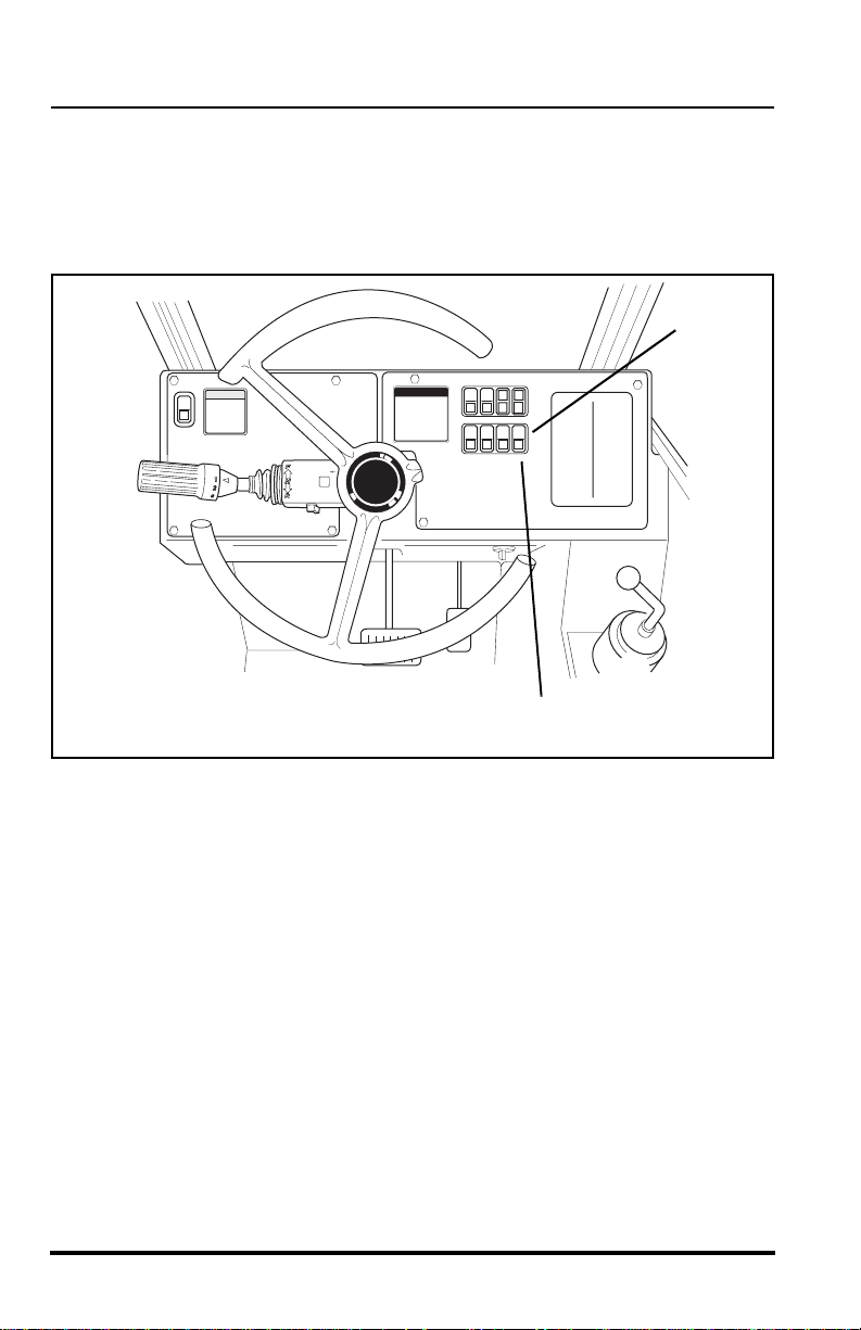
Steering Select Switch
This vehicle has one steering select switch (1) with three positions. The
switch is located in the lower switch bank (2) on right side dash panel.
Refer to “Steering Modes” on page 68 for detailed information.
2
26
1
Model 10042 Rev. 11/03
OH3240
Park Brake Switch
The Parking Brake Switch (3) has two positions:
ENGAGED ............toggle switch downward
P
Operation
OS0121
P
DISENGAGED............toggle switch upward
OS1323
The Parking Brake Switch (3) must be ENGAGED to permit engine starting.
A red LED, on the parking brake switch, and a light in the instrument cluster
will indicate the brake is ENGAGED.
The parking brake may be used to stop in an EMERGENCY situation.
However, use caution because the stop will be abrupt and the operator and
the load may be jolted forward unexpectedly.
With boom angles greater than 40°, this switch activates the locked mode of
the Stabil-TRAK system.
3
Model 10042 Rev. 11/03
OH3240
27
Operation
N D
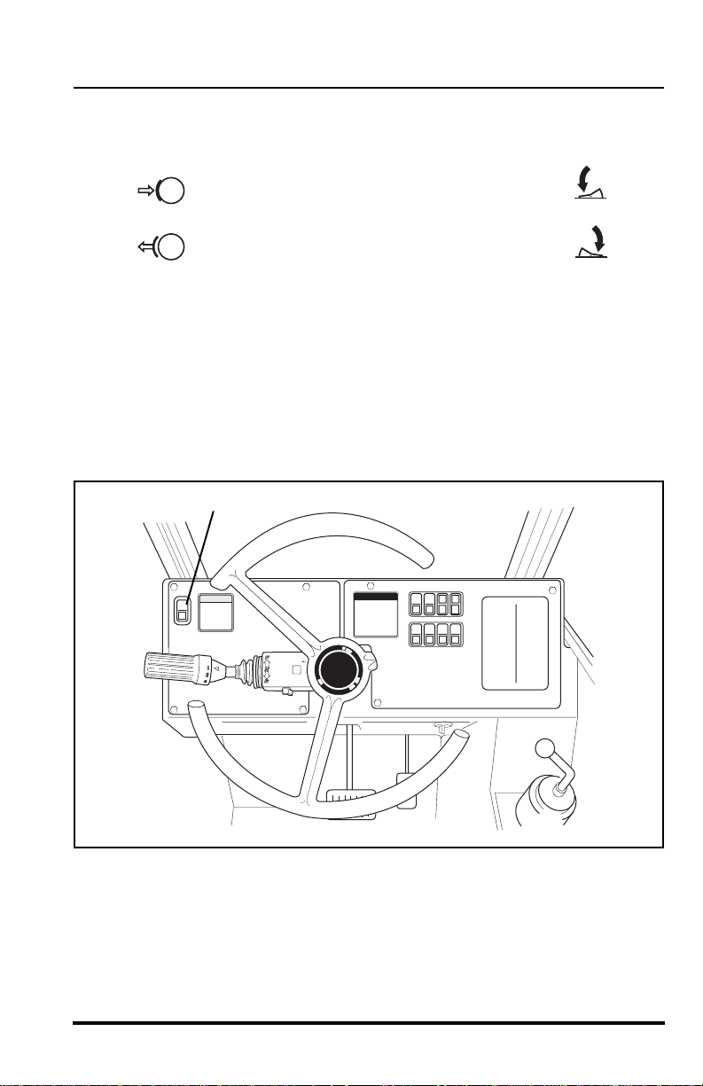
Neutral Lock Lever
The Travel Select Lever (1) is equipped with a neutral lock. The Neutral Lock
Lever (2) locks the Travel Select Lever in NEUTRAL or unlocks the Travel
Select Lever so that it can be moved into the FORWARD or REVERSE drive
position.
2
1
OH3250
To lock the Travel Select Lever (1) in the NEUTRAL position, place the lever
in the NEUTRAL position and move the Neutral Lock Lever (2) to the (N)
NEUTRAL LOCK position.
To unlock, move the Neutral Lock Lever to the (D) DRIVE position.
N = NEUTRAL LOCK .................. all the way LEFT
OT0570
D = DRIVE ...................................all the way RIGHT
OT0580
28
Model 10042 Rev. 11/03

Operation
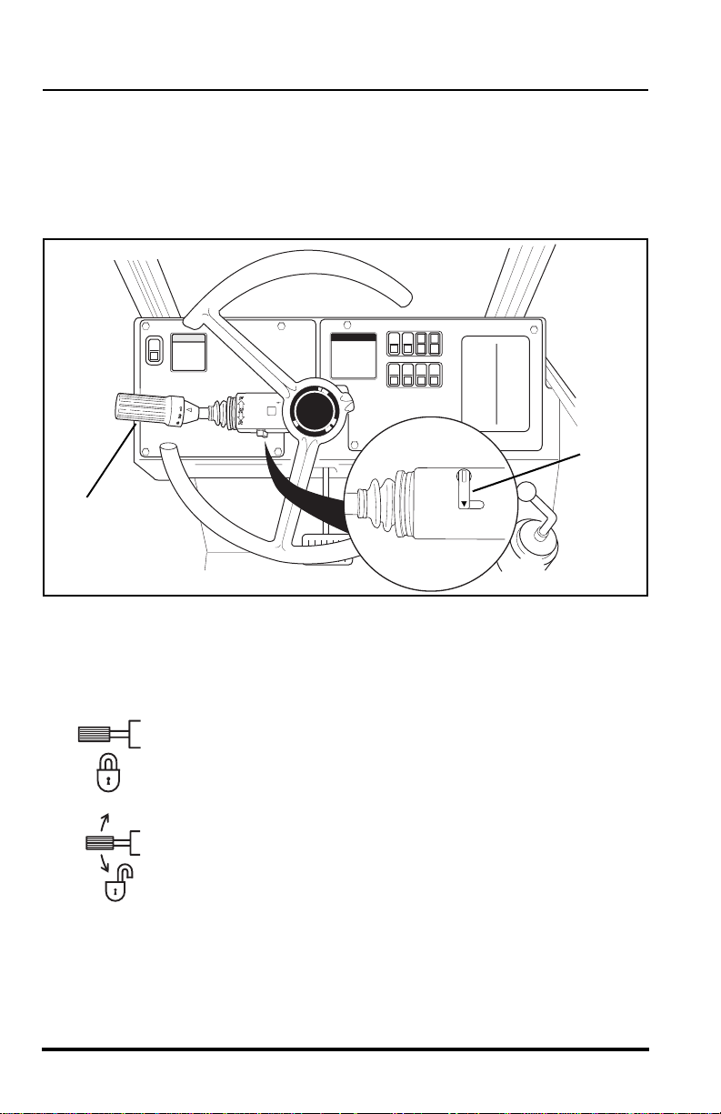
Travel Select Lever
The Travel Select Lever (3) has three positions to select direction of travel:
F = FORWARD (4) ......... all the way FORWARD
N = NEUTRAL (5) .......... CENTER position
R = REVERSE (6) ...........all the way REARWARD
OS0340
4
5
6
3
OH3260
To change travel selections, move the lever FORWARD or REARWARD to
the desired selection.
When the Travel Select Lever is shifted to REVERSE, the back-up alarm will
automatically sound.
NOTE: The Travel Select Lever must be in the (N) NEUTRAL position to
permit engine starting and when boom angles are greater than 40°, shifting
into NEUTRAL activates the locked mode of the Stabil-TRAK system.
Model 10042 Rev. 11/03
29

Operation
Gear Select Lever
The Gear Select Lever (1) has a twist grip handle with four positions.
Vehicles have four forward gears and three reverse gears.
1
OH3270
Use first gear for highest torque and pulling power. Use higher gears for
higher ground speed. The recommendations listed in the table that follows
are guidelines only. Always use good judgement when traveling with a load.
Recommended Gear/Speed for Various Load/Travel Conditions
Load Size Surface Gear Speed
No Load Smooth 4th* 0 to 20 mph (0 to 32 km/h)
Improved 3rd 0 to 14 mph (0 to 23 km/h)
Rough 2nd 0 to 6 mph (0 to 9,7 km/h)
Load Smooth 3rd 0 to 14 mph (0 to 23 km/h)
up to 4,500 lbs Improved 2nd 0 to 6 mph (0 to 9,7 km/h)
(up to 2.041 kg)
Load Smooth 3rd 0 to 14 mph (0 to 23 km/h)
4,500 to 8,000 lbs Improved 2nd 0 to 6 mph (0 to 9,7 km/h)
(2.041 to 3.629 kg)
Load Smooth 2nd 0 to 6 mph (0 to 9,7 km/h) 8,000 to 10,000 lbs Improved 1st 0 to 3.5 mph (0 to 5,6 km/h) (3.629 to 4.536 kg)
Rough 2nd 0 to 6 mph (0 to 9,7 km/h)
Rough 1st 0 to 3.5 mph (0 to 5,6 km/h)
Rough 1st 0 to 3.5 mph (0 to 5,6 km/h)
*NEVER travel in 4th gear when carrying a load.
30
Model 10042 Rev. 11/03

Operation
Boom Control Lever
The boom control lever (2) is a joystick with variable motion from the center
to control the boom functions:
Boom Lift............................. move lever backward
Boom Lower........................ move lever forward
Boom Extend .......................move lever to the right
OH0170
Boom Retract.......................move lever to the left
Two boom functions can be accomplished at the same time by moving the
lever into the proper quadrant. For example: moving the lever forward and to
the left will lower and retract the boom simultaneously.
The speed of the function depends directly upon the amount of lever travel
in the corresponding direction. Increasing the engine speed will also
increase the function speed.
2
Model 10042 Rev. 11/03
OH1700
31

Operation
Attachment Tilt and Frame Sway Control Lever
The attachment tilt and frame sway control is a joystick (1) with four
perpendicular motions from the center to control two attachment tilt
functions and two frame sway functions:
Frame Sway Left .................move lever to the left
Frame Sway Right ...............move lever to the right
Attachment Tilt Down .......... move lever forward
OH0410
Attachment Tilt Up............... move lever backward
The attachment is self leveling and will retain any set angle throughout
boom lifting, lowering, retracting or extending operations.
1
OH1700
32
Model 10042 Rev. 11/03

Operation
Outrigger Control Switches
The left (2) and right (3) outrigger control switches raise or lower the
corresponding outriggers. The rocker switches are spring loaded to return to
the center (stop) position when released.
Raise Left Outrigger............ press top of left side switch
Lower Left Outrigger ........... press bottom of left side switch
Raise Right Outrigger ..........press top of right side switch
Lower Right Outrigger..........press bottom of right side switch
OH0420
2
Model 10042 Rev. 11/03
3
OH1700
33

Operation
IMPORTANT! Outrigger equipped vehicles can be used with the outriggers
in either the raised or lowered position. The operator must operate the
vehicle within the limits specified on the appropriate capacity chart for the
outrigger position (up or down).
Procedure for Lowering of Outriggers
Secure and proper outrigger placement is critical for stability of the vehicle.
Avoid holes or drop-offs and soft or excessively uneven terrain. Lower
outriggers just far enough until the front of the vehicle starts to raise and
maintain a level position. Use the following procedure to assure that both
outriggers have been lowered securely.
IMPORTANT! For optimum vehicle stability, never lower the outriggers to
the point at which the tires come completely off the ground.
1. Before locating the vehicle at the lift point, observe that the landing
area for the outriggers is free of loose material or debris and that
the terrain appears to be solid and free of holes.
2. Position the vehicle at the lift point and level the vehicle to
zero degrees (0°). If the vehicle cannot be leveled, reposition the
vehicle.
3. Lower the right outrigger until the right front tire just starts to raise
and maintains this position.
4. Lower the left outrigger until the left front tire just starts to raise and
again maintains this position.
5. Frame sway the vehicle back to level (0°) if necessary.
34
Model 10042 Rev. 11/03

Operation
Seat Belt
WARNING: Death or serious personal injury may result
from failure to wear the seat belt installed on this vehicle. The seat
belt is a critical component of the Operator’s protective Structure,
and is provided for the operator’s protection in case of vehicle
upset. The seat belt MUST be worn whenever this vehicle is operated.
IMPORTANT! Inspect the seat belt every time it is used, looking for cut or
worn webbing, or any defect in the latch assembly. If any wear or damage is
noted, DO NOT operate the vehicle until the seat belt is replaced.
Before the engine is started, adjust the seat as required for position and
comfort. Then adjust the seat belt as follows:
1. Grasp both free ends of the belt and make certain that the belt webbing is not twisted or entangled in any portion of the seat assembly.
2. With your back straight in the seat, couple the retractable end or the
male end of the belt into the receptacle (buckle) end of the belt.
3. With the belt buckle as low on your body as possible, pull the
retractable end of the belt or the free end of the belt away from the
buckle until it is tight across the lap.
STANDARD 2 INCH WIDE
SEAT BELT
1
4. To release the belt latch, depress the red button (1) or lift the black
cover (2) of the buckle (dependant on belt style installed), and pull
the free end (3) from the buckle.
An optional 3 inch wide seat belt is available for those locations that require
a 3 inch seat belt.
Model 10042 Rev. 11/03
3
OPTIONAL 3 INCH WIDE
SEAT BELT
2
3
OL0430
35

Operation
Operator’s Seat Adjustment
The operator’s seat can be adjusted three ways:
A. Fore and Aft Adjustment
Pull the handle (1) outward to adjust the seats forward and
backward. Release the handle to lock the seat in the desired
position.
B. Suspension Adjustment
Turn the knob (2) on the front of the seat (3) to adjust the
suspension to correspond with the operator’s weight. Turn
clockwise to increase stiffness. Turn counter-clockwise to reduce
the stiffness.
C. Backrest Angle Adjustment
The angle of the seat backrest can be adjusted to suit the operator.
Move the lever (4) located on the left side of the seat backrest (5) to
adjust the angle.
36
5
3
2
1
Model 10042 Rev. 11/03
4
OH1820

Operation
Instruments and Indicators
Hourmeter
OS0260
The hourmeter (6) records engine operating hours and has a total readout
of 9,999.99 hours. It is located at the lower portion of the instrument cluster
(7) on the right side console.
Fuel Gauge
OH2470
The fuel gauge (8) indicates the quantity of fuel in the fuel tank. The gauge
is located in the center of the instrument cluster (7) on the right side
console. Capacity of the fuel tank is 37 gallons (140 liters) total capacity
with a usable capacity of 35.6 gallons (135 liters).
8
6
Model 10042 Rev. 11/03
P
7
0000 00
OH1810
37

Operation
Instrument Cluster Light Test
Test the bulbs in the instrument cluster before starting the engine.
Turn the ignition switch to the RUN position, ALL nine lights in the
instrument cluster will come ON for a few seconds and then go out. Replace
any bulbs that DO NOT come ON during this test. These lights will warn the
operator if an abnormal condition should arise during operation and will also
inform the operator when the Stabil-TRAK system is active, road lights are
on high beam or the turn signals are activated.
(1)
(2) (3)
(4) (5)
(6) (7)
(8) (9)
Position of corresponding lights:
• Alternator Charging Light (1)
• Park Brake Light (2)
• Engine Oil Pressure Light (3)
• Engine Coolant Temperature Light (4)
• Hydraulic Tank Temperature Light (5)
• Transmission Temperature Light (6)
• High Beam Light (7)
• Stabil-TRAK Light (8)
• Turn Signal Light (9)
P
0000 00
OH1810
38
Model 10042 Rev. 11/03

Function Indicator Lights
A. Stabil-TRAK Indicator Light
Operation
The Stabil-TRAK light (8) will come
ON when the system has been
activated. The rear axle will lock
when one or more of the following conditions exist with the boom above
a 40° angle.
• Parking Brake Switch engaged
• Travel select lever in (N) NEUTRAL
• Service brake pedal depressed and held
With the boom above a 40° angle and traveling in a forward or reverse
drive gear, the Stabil-TRAK Light will go OFF. In this condition the rear
axle is unlocked and is allowed to pivot, but will respond slowly
changes in terrain.
ALWAYS be sure the Stabil-TRAK system is functioning properly when
operating vehicle. Refer to “Understanding the Stabil-TRAK System”
later in this manual for a detailed explanation of this system.
OH2500
to
DANGER: Vehicle tipover can result in death or serious
injury. Traveling with the boom raised is dangerous and can cause
vehicle tipover. Keep the load as low as possible. Travel with
extreme caution
and at the slowest possible speed.
Model 10042 Rev. 11/03
39

Operation
B. Park Brake Light
The park brake light (1)
illuminates any time the
P
OH2480
park brake is applied
and the ignition switch is
in the RUN position.
C. High Beam Light
(used with optional road
light package only)
The high beam light (2) illuminates when the road option headlights are
on full (high) beam and will turn OFF when the headlights are switched
to low beam.
OH2490
D. Turn Signal Light
(used with optional road
light package only)
The turn signal light (3) will
illuminate and flash when the road option turn signals are activated in
either direction or when the road option hazard lights are activated.
1
P
4
OH2510
6
2
40
5
0000 00
3
OH1810
Model 10042 Rev. 11/03

Operation
Warning Indicator Lights
There are five additional indicator lights in the instrument cluster that will
illuminate during critical circumstances. All five warning indicator lights
demand immediate attention and vehicle servicing. In many cases, the
vehicle should be shut down AS SOON AS PRACTICAL
mechanical failure.
The five warning indicator lights are:
A. Engine Coolant Temperature Warning Indicator Light
OH2520
The engine coolant temperature warning light (4) illuminates when
the engine coolant temperature is too high; above 210° F (99° C).
SHUT THE VEHICLE DOWN AS SOON AS PRACTICAL.
B. Transmission Temperature Warning Indicator Light
OH2530
to prevent serious
The transmission temperature warning light (5) illuminates when
the transmission oil temperature is too high; above 250° F (121° C).
Stop and idle the vehicle in NEUTRAL, allowing time for cooling. If
the light does not go out after two minutes, shut the vehicle down.
C. Hydraulic Oil Temperature Warning Indicator Light
OH2540
The hydraulic oil temperature warning light (6) illuminates when the
hydraulic oil temperature is too high; above 195° F (91° C). Stop
and idle the engine, allowing time for cooling. If the light does not go
out after five minutes, shut the vehicle down.
Model 10042 Rev. 11/03
41

Operation
D. Engine Oil Pressure Warning Indicator Light
OH2550
The engine oil pressure warning indicator light (1) will come ON
during engine start-up and go OUT once the engine has started.
This is normal. If the light comes ON while the engine is running,
this indicates that the engine oil pressure is too low.
SHUT THE VEHICLE DOWN AS SOON AS PRACTICAL
2
P
.
1
0000 00
E. Alternator Charging Warning Indicator Light
OH2560
The alternator charging warning light (2) illuminates when the
charging system is not working properly. Service the engine
alternator.
42
OH1810
Model 10042 Rev. 11/03

Operation
Function Indicator Lights
There are two additional indicator lights located on the right side of the front
dash.
A. Engine Air-Intake Heater Indicator
The engine air-intake heater indicator
light (3) located in the upper switch bank
OU0040
on the right side of the front dash. This
light illuminates, with the ignition switch in the RUN position, any
time the ambient temperature drops below 40° F (4° C). The engine
grid heater then becomes active and the engine should not be
cranked until the light goes OFF. Once the light goes OFF it
indicates that the grid heater is at the proper temperature and the
engine is ready to start.
NOTE: This indicator light may come ON when the engine is running to indicate that the post heat function is active. This is a normal condition when
ambient temperatures are below 40° F (4° C).
3
Model 10042 Rev. 11/03
OH3490
43

Operation
B. Engine Function Indicator Lights
The engine function indicator lights (1)
are located in the upper switch bank on
the right side of the front dash. The light
indicates any faults that arise in the
engine during operation. The light contains a RED light (2) and a
AMBER light (3).
23
OH3290
If the RED light (2) comes ON during operation, STOP
IMMEDIATELY
and diagnose the fault by activating the ECM
diagnostic system. Activate the system with the accelerator pedal.
Activate the system and read the code as indicated by the RED
light. Contact your local Cummins dealer for an explanation of these
codes or refer to the Cummins Engine Owners Manual or call the
Cummins Customer Assistance Center at 1-800-343-7357.
If the AMBER light (3) comes ON during operation, the engine
diagnostic system has detected a fault within the engine. Stop the
engine and diagnose the fault by activating the ECM diagnostic
system.
Activate the system and read the code as indicated by the light.
Contact your local Cummins dealer for an explanation of these
codes or refer to the Cummins Engine Owners Manual or call the
Cummins Customer Assistance Center at 1-800-343-7357.
Cummins ECM Diagnostic System Activation
With the engine OFF, turn the ignition switch to the RUN position.
DO NOT start the engine.
Completely depress and release the accelerator pedal three times.
This will activate the system, both the AMBER light and RED light
will come ON momentarily and then both will begin to flash the
code. If the system has been activated with the accelerator pedal
and no faults are present, both the AMBER light and the RED light
will come ON and stay ON.
the engine
ECM Light Code Identification
The AMBER light will flash one time to identify the start of the code
followed by a one or two second pause. Then the RED light will
flash the code sequence, pausing for one or two seconds between
numbers. The AMBER light will flash once after the RED light has
flashed the code to signify the end of that fault code.
44
Model 10042 Rev. 11/03

Operation
2
1
3
OH3500
Frame Level Indicator
The indicator (4) is mounted on the top inside of the Operator's Protective
Structure (cab). This is a bubble type indicator which allows the operator to
tell if the vehicle has been positioned in a level condition. Always frame
sway the vehicle either right or left until the indicator reads zero degrees
(0°). If zero cannot be achieved, then reposition the vehicle until it is level
before placing the load.
NOTE: Maximum frame sway is 10° in either direction.
4
Model 10042 Rev. 11/03
OS0232
45

Operation
Boom Angle Indicator
The boom angle indicator is a plumb arrow (1) with angular graduations (2)
from minus 10° to plus 80°. It is located on the left side of the boom and is
visible from the operator’s position. Use this indicator to determine the
boom angle when reading the capacity chart (see “Using The Capacity
Chart”).
4105262
1
2
OH0302
Rear View Mirrors
Two rear view mirrors are provided to aid the operator's rear vision. A
rectangular flat lens mirror (3) is mounted on the upper left of the cab. A
convex lens mirror (4) is mounted on the right side of the frame. Both
mirrors are adjustable to obtain the best rear view by the operator.
46
4
3
OH1830
Model 10042 Rev. 11/03

Operation
Optional Controls
Auxiliary Attachment Control Lever
The auxiliary attachment control lever (5) controls the functions of an
optional attachment that is mounted to the vehicle and requires a hydraulic
supply for operation. Some of the optional attachments that require auxiliary
hydraulics are: Side Tilt Carriage, Swing Carriage, Auger, and 3 Foot Truss
Boom w/Winch.
When the control lever is moved to the right
it will provide
hydraulic system pressure through the female disconnect
coupling for the auxiliary attachment. Hydraulic fluid will return
OH0431
to the tank through the male disconnect coupling.
When the control lever is moved to the left it will provide
hydraulic system pressure to the male disconnect coupling for
the auxiliary attachment. Hydraulic fluid will return to the tank
OH0451
through the female disconnect coupling.
The control lever will provide the following typical functions for each specific
attachment if they are connected properly. Operation will be reversed if
incorrectly connected. We recommend reversing the disconnect couplings
on the hoses that are supplied with the attachment if operation is reversed.
Side Tilt Carriage Operation:
• Control Lever right...................... tilt right
• Control Lever left........................ tilt left
Swing Carriage Operation:
• Control Lever right...................... swing right
• Control Lever left........................ swing left
Auger Operation:
• Control Lever right...................... auger dig
• Control Lever left........................ auger retract
3 FootTruss Boom w/Winch Operation:
• Control Lever right...................... cable extends
• Control Lever left........................ cable retracts
5
Model 10042 Rev. 11/03
OH1710
47

Operation
Worklight Switch (Front, Rear & Boom Worklights)
OH2570
This three position rocker switch (1) controls the front, rear and boom
worklights. The switch is located in the upper switch bank on the right side
dash panel. These lights will only operate when the ignition switch is in the
RUN position.
• Push the top of the switch in to turn all the
worklights OFF.
OH2591
• To turn the front and boom worklight ON,
position the rocker switch to the center
position.
• Push the bottom of the switch in to turn all the
worklights ON.
1
OH2601
OH2611
OH3300
48
Model 10042 Rev. 11/03

Operation
Beacon Light Switch
OH2580
This rocker switch (2) turns the beacon light ON and OFF. The switch is
located in the lower switch bank on the right side dash panel. This light will
only operate when the ignition switch is in the RUN position.
• Push the bottom of the switch in to turn the
beacon light ON.
OH2611
• Push the top of the switch in to turn the
beacon light OFF.
OH2591
2
OH3310
Model 10042 Rev. 11/03
49

Operation
Worklight Switch (with Optional Road Lights)
OH2620
This rocker switch (1) activates the worklight system. The switch is located
in the upper switch bank on the right side dash panel. This system will only
operate when the ignition switch is in the RUN position. See “Parking Lights,
Headlights & High/Low Beam Switch” on page 52 for operation of the road
lights.
• Push the top of the switch IN to
DEACTIVATE the entire the worklight
system.
• To ACTIVATE the boom worklight
position the rocker switch to the center
position.
• Push the bottom of the switch IN to
ACTIVATE the boom worklight and
rear worklights.
OH2591
OH2601
OH2611
50
1
OH3320
Model 10042 Rev. 11/03

Operation
Emergency Flashers
OS1920
This switch (2) is located in the upper switch bank on the right side dash
panel.
• To ACTIVATE the emergency flashers, push
the bottom of the switch IN.
• To DEACTIVATE the emergency flashers
push the top of the switch IN.
2
OH2611
OH2591
Model 10042 Rev. 11/03
OH3320
51

Operation
Turn Signals
OH2510
The directional signals are ACTIVATED from the lever (1) on the right side
of the steering wheel and will only operate when the ignition switch is in the
RUN position.
To activate the left turn signal (2), raise the lever. To activate the right turn
signal (3), lower the lever. To deactivate either directional signal, the lever
must be manually returned to the center position. The lever will not cancel
automatically after a turn.
Parking Lights, Headlights & High/Low Beam Switch
With the ignition switch in the RUN position use the turn signal switch to
control the high/low beam headlights, turn on the parking lights and the
headlights. Turn the twist grip end of the turn signal switch counterclockwise to the first position (4) to turn the parking lights ON. Turn the twist
grip to the second position (5) to turn the headlights and parking lights ON.
Turn the twist grip clockwise to the OFF position (6) to turn all the lights
OFF. Pull the turn signal switch toward you to switch from low beam to high
beam. When the high beam is ON the high beam indicator light will
illuminate.
52
1
2
3
6
4
5
Model 10042 Rev. 11/03
OH3330

Operation
Windshield Wiper Control
OS1930
This three position rocker switch (7) controls the speed of the windshield
wiper. This switch is located in the lower switch bank on the right side dash
panel.
• To STOP the windshield wiper, push
the top of the switch IN.
• To OPERATE the windshield wiper at
LOW speed, position the switch in the
CENTER POSITION.
• To OPERATE the windshield wiper at
HIGH speed, push the bottom of the
switch IN.
OH2591
OH2601
OH2611
Model 10042 Rev. 11/03
7
OH3310
53

Operation
Skylight Wiper Control
OH1900
This rocker switch (1) turns the skylight wiper ON and OFF. This switch is
located in the lower switch bank on the right side dash panel.
• Push the bottom of the switch IN to turn the
skylight wiper ON.
OH2611
• Push the top of the switch IN to turn the
skylight wiper OFF.
OH2591
Windshield & Skylight Washer Control
OS1940
This rocker switch (2) is spring loaded to return to the OFF position when
released. This switch is located in the lower switch bank on on the right side
dash panel.
• Pressing down on the bottom of the switch
will dispense washer fluid to the windshield
and skylight wiper at the same time. The
switch must be held in place to activate the
washer control.
• Release the switch to deactivate the washer
control.
OH1910
OH2611
OH2591
54
OH3310
1
2
Model 10042 Rev. 11/03

Operation
Cab Heater & Fan Control
OS1950
The cab heater controls (3) are located directly below the switch banks on
the right side dash panel. The control panel consists of: a variable speed
fan control knob (4) and a temperature control knob (5).
Control of air flow to the windshield is made by opening, closing or
redirecting the air vent louver on the front dash. The cab is heated by the
heater unit positioned under the operators seat.
To heat the cab:
OS1950
• Turn temperature control knob (5) to far right position
(RED = HOT),
• Direct desired air flow by adjusting vent louvers,
• Turn fan control (4) to “3” (6) to assure rapid warm-up.
To defrost the cab:
• Turn temperature control knob (5) to the far right position
(RED = HOT),
• Direct desired air flow by adjusting vent louver,
• Turn fan control (4) to “3” (6) to assure rapid defrost.
4
Model 10042 Rev. 11/03
OA1390
6
5
3
OH3340
55

Operation
Rear Window Latch
The rear window (1) can be partially opened and secured in place with the
rear window latch (2). To open the window, grab the latch handle and pull up
and then push the window outward. To close and secure the window, pull
the latch handle forward and down.
NOTE: In an emergency situation, the operator can exit through the rear
window opening by removing the latch pin (3) on the window latch. The window is then free to swing open.
1.
3
2.
3.
2
1
4
1
0
97
9
1
OH1730
Door Latches
(not pictured)
There are two door latches. The outside latch is a key lockable pull-to-
release type. The inside latch is also a pull-to-release latch.
Door Window Latch
(not pictured)
The door window can be swung open by releasing the window from inside
the cab. Swing the window all the way open and lock in place on the outside
of the cab. To release the window from the open position, push up the
release on the lower side of the outside hold or release using the release on
the side wall of the cab below the left side window.
56
Model 10042 Rev. 11/03

Operation
Pre-Operation Inspection
1. Check safety belt for damage. Check for frayed or cut seat belt webbing, damaged buckles or loose mounting brackets. Make any necessary repairs before operating the vehicle.
2. Check all four tires and rims for damage. Check for proper tire pressure, add air if required. Observe the condition of each tire looking
specifically for punctures, cracks, cuts, gouges, bulges or any other
damage. Check the condition of each rim for bent flanges or any
other damage. Make any necessary repairs before operating the
vehicle.
3. Check and add engine oil if required. This procedure is explained in
greater detail on page 125.
4. Check and add transmission oil if required. This procedure is
explained in greater detail on page 139.
5. Check the cooling system overflow bottle for coolant. Add coolant if
required. This procedure is explained in greater detail on page 122.
Remove any debris blocking the radiator cooling fins.
6. Check the hydraulic oil level sight glass and add hydraulic oil if
required. This procedure is explained in greater detail on page 136.
7. Walk around the vehicle and check for oil leakage as well as damaged or missing parts. Make any necessary repairs before operating the vehicle.
Model 10042 Rev. 11/03
57

Operation
Normal Starting
1. Enter the cab using the hand holds and adjust the seat for comfortable operation.
2. Adjust the mirrors to obtain the best rear view from the operator’s position.
WARNING: DO NOT start the engine unless you are in the
seat with the seat belt fastened around you. Death or serious personal injury could result if the belt is not securely fastened.
3. Fasten the seat belt.
4. Make sure the parking brake switch is ENGAGED.
5. Place the travel select lever in (N) NEUTRAL and move the neutral
lock lever to NEUTRAL LOCK position.
6. Turn the ignition switch to the START position (fully clockwise) to
crank the engine. Release the key when the engine starts. If the
engine fails to start on the first try, wait until the engine and starter
come to a complete stop before cranking the engine again.
IMPORTANT! DO NOT crank the starting motor continuously for more than
30 seconds. Stop cranking the starter and allow the starter to cool for 2
minutes before engaging the starter again.
7. After the engine starts, run engine at partial throttle for 30 to 60 seconds before operating the vehicle. Return to idle before engaging
the travel or range select lever.
8. Move the Neutral Lock Lever to the (D) DRIVE position before you start operating.
9. Disengage the parking brake switch before you start operating.
58
Model 10042 Rev. 11/03

Operation
Cold Starting
The engine is equipped with a 120 volt 750 watt block heater. Block heaters
are recommended when temperatures drop below 10° F (-12° C).
(Temperature ranges will vary when using different oil weights. Consult the
engine manufacturer’s manual for other variables.)
WARNING: This diesel engine uses a grid heating system
inside the induction manifold. DO NOT use ether or any high
energy fuels to assist starting. An explosion may cause death or
serious personal injury or engine damage.
The engine is equipped with a grid heater inside the induction manifold. If
the temperature drops below 40° F (4° C) the air-intake heater system will
be activated when the ignition switch is turned to the RUN position. When
the system is active the air-intake heater light (see page 43) will illuminate
on the front dash. DO NOT turn the ignition switch to START until the airintake heater light goes OFF.
At temperatures below -10° F (-12° C), operate the engine at moderate
speeds for 5 minutes before full loads are applied.
1. Enter the cab using the hand holds and adjust the seat for comfortable operation.
2. Adjust the mirrors to obtain the best rear view from the operator’s position.
WARNING: DO NOT start the engine unless you are in the
seat with the seat belt fastened around you. Death or serious personal injury could result if the belt is not securely fastened.
3. Fasten the seat belt.
4. Make sure the parking brake switch is ENGAGED.
5. Place the travel select lever in (N) NEUTRAL and move the neutral
lock lever to NEUTRAL LOCK position.
6. Turn the ignition switch to the START position to crank the starter.
IMPORTANT! DO NOT crank the starting motor continuously for more than
30 seconds. Stop cranking the starter and allow the starter to cool for 2
minutes before engaging the starter again.
7. As the engine starts, release the ignition switch to the RUN position. Depress the accelerator pedal enough to provide a smooth
idle speed.
Model 10042 Rev. 11/03
59

Operation
8. The engine oil pressure warning indicator light should go OFF
within five seconds after starting. If the light remains ON, turn the
ignition switch OFF immediately and check the oil level or change
to a lighter weight oil. Consult the engine manufacturer’s manual for
alternative oils for cold weather operation.
Jump Starting
Jump starting at the batteries or battery replacement is required when the
batteries are discharged to the point where the batteries will not crank the
starter.
WARNING: NEVER jump start the vehicle directly to the
starter solenoid. Death or serious personal injury could result from
the vehicle lurching forward or backward and running over the person attempting to jump start the vehicle directly to the starter.
WARNING: To avoid death or serious personal injury when
jump starting with another vehicle, be certain that the two vehicles
are not touching. Never jump start a frozen battery as it will
explode. Keep sparks, flames and lighted smoking materials away
from the battery. Lead acid batteries generate explosive gases
when charging. Wear safety glasses when working near batteries.
The booster battery must be a 12 volt type. The vehicle used for jump
starting must have a negative ground electrical system. To jump start the
vehicle, proceed as follows:
1. Connect the positive (+) jumper cable to the positive (+) post of the discharged battery.
2. Connect the other end of the positive (+) jumper cable to the positive (+) post of the booster battery.
3. Connect one end of the negative (-) jumper cable to the negative (-) post of the booster battery.
4. Make the final cable connection to the furthest point from the batteries.
5. Follow the steps in “Normal Starting” on page 58.
6. Remove the jumper cables in the reverse order of their connection
(i.e. negative cable ground connection first, etc.).
60
Model 10042 Rev. 11/03

Operation
Refueling
Make sure the vehicle is level to assure an accurate fuel level reading. The
fuel tank is capable of holding 37 gallons (140 liters) of diesel fuel. The
usable capacity of the fuel tank is 35.6 gallons (135 liters).
Fuel Types
OH0480
Use ASTM #2 diesel fuel with a minimum Cetane rating of 40. #2 diesel fuel
gives the best fuel economy and performance under most operating
conditions. Fuels with Cetane ratings higher than 40 may be needed in
higher altitudes or extremely low ambient temperatures to prevent misfiring
and excessive smoke.
• When operating at temperatures above 32° F (0° C), use
standard #2 diesel fuel.
• When operating at temperatures below 32° F (0° C), use a blend
of #1 & #2 diesel fuels, most commonly known as “winterized” #2
diesel.
WARNING: Engine fuel is flammable and can cause a fire
or an explosion. Keep sparks and open flames away from the
vehicle and DO NOT use smoking materials while refueling.
Model 10042 Rev. 11/03
61

Operation
Fuel Cap
Unlock the fuel cap (1) through the fuel cap access hole (2).
Slowly remove the fuel cap from the fuel fill neck.
Fill fuel tank.
2
1
OH1920
Reassemble the fuel cap onto the fill neck and turn to lock in place. Line up
the locking tabs to reassemble a lock if desired.
62
Model 10042 Rev. 11/03

Operation
Stabil-TRAK System
Understanding the Stabil-TRAK System
OS1970
The following describes the three basic modes of the patented Stabil-TRAK
system. The vehicle may operate in any one of these three modes.
Free Pivot Mode
With the boom below 40° (3), the Stabil-TRAK system is in the FREE PIVOT
MODE (4) and the rear axle is allowed to pivot freely. The frame sway will
function normally with or without the outriggers down. The Stabil-TRAK light
will be OFF (5).
3
4
5
OH0703
Model 10042 Rev. 11/03
63

Operation
Locked Mode
With the boom above 40° (1) and by activating one or more of the functions
(as follows), the Stabil-TRAK system is in the LOCKED MODE (2). The rear
axle is locked so it is rigid with the frame. The Stabil-TRAK light will be ON
(3).
• Engaging the parking brake switch
• Placing the travel select lever in (N) NEUTRAL
• Depressing and holding the service brake pedal
The frame sway will function slower than normal in this mode with or without
the outriggers down.
2
1
3
OH0713
64
Model 10042 Rev. 11/03

Operation
Slow Pivot Mode
With the boom above 40° (4), the Stabil-TRAK System is now in the SLOW
PIVOT MODE (5). In this mode the rear axle is UNLOCKED and is allowed
to pivot but will respond SLOWLY
light will be OFF (6).
The frame sway will function normally in this mode.
To check that the Stabil-TRAK System is functioning properly, refer to the
test procedure on page 175 for the proper system function.
to changes in terrain. The Stabil-TRAK
5
4
6
OH0724
Model 10042 Rev. 11/03
65

Operation
Operating
Starting Travel
1. Enter the operator cab, fasten the seat belt, start the engine, apply
the service brake pedal and disengage the parking brake switch.
2. Rotate the twist grip of the range select lever (1) to 1st gear.
3. Move the travel select lever (2) to (F) FORWARD to travel in a forward direction or to (R) REVERSE to travel backward.
4. Slowly remove your foot from the service brake pedal and press the
accelerator pedal to start travel.
IMPORTANT! Check for warning lights frequently during operation. Any
abnormal indication should be corrected as soon as practical.
Changing Travel Direction
1. Stop the vehicle by applying the service brakes.
2. Grasp the travel select lever, pull it toward the steering wheel, then
move the lever up or down in the opposite direction;
(R) REVERSE or (F) FORWARD.
66
1
OH3270
2
OH3260
Model 10042 Rev. 11/03

Operation
Shifting Gears
1. Rotate the twist grip of the gear select lever to the next desired
gear. The transmission has four forward gears and three reverse
gears.
2. Use first gear for highest torque and pulling power. Use higher
gears for higher ground speed. The recommendations listed in the
table that follows are guidelines only. Always use good judgement
when traveling with a load.
Recommended Gear/Speed for Various Load/Travel Conditions
Load Size Surface Gear Speed
No Load Smooth 4th* 0 to 20 mph (0 to 32 km/h)
Improved 3rd 0 to 14 mph (0 to 23 km/h)
Rough 2nd 0 to 6 mph (0 to 9,7 km/h)
Load Smooth 3rd 0 to 14 mph (0 to 23 km/h)
up to 4,500 lbs Improved 2nd 0 to 6 mph (0 to 9,7 km/h)
(up to 2.041 kg)
Load Smooth 3rd 0 to 14 mph (0 to 23 km/h)
4,500 to 8,000 lbs Improved 2nd 0 to 6 mph (0 to 9,7 km/h)
(2.041 to 3.629 kg)
Load Smooth 2nd 0 to 6 mph (0 to 9,7 km/h) 8,000 to 10,000 lbs Improved 1st 0 to 3.5 mph (0 to 5,6 km/h) (3.629 to 4.536 kg)
Rough 2nd 0 to 6 mph (0 to 9,7 km/h)
Rough 1st 0 to 3.5 mph (0 to 5,6 km/h)
Rough 1st 0 to 3.5 mph (0 to 5,6 km/h)
*NEVER travel in 4th gear when carrying a load.
NOTE: Shifting to the next higher gear may be done while the vehicle is in motion.
IMPORTANT! When downshifting, allow the engine speed to slow down
before shifting to the next lower gear.
Stopping Travel
1. Apply the service brake pedal and downshift the vehicle to a lower
gear if necessary to slow the vehicle until it comes to a complete
stop.
2. Move the travel select lever to (N) NEUTRAL and engage the parking brake switch. For longer stops, place the neutral lock lever to
NEUTRAL LOCK position and engage the parking brake switch.
Model 10042 Rev. 11/03
67

Operation
Steering Modes
IMPORTANT! DO NOT change steering modes unless you are at a
complete stop and all four tires are in the “straight-ahead” position.
The three steering modes are:
• Four Wheel Steering (1)
• Front Wheel Steering (2)
• Crab Steering (3)
The steering modes can be changed using a single rocker switch (4)
located in the lower switch bank on the right side dash panel.
4
68
3
2
1
OH3360
Model 10042 Rev. 11/03

Operation
Four Wheel Steer Indexing
If the vehicle does not drive “straight,” the steering could be ”out of phase.”
Perform the “Four Wheel Steer Indexing Procedure” on page 181 to
synchronize the front and rear steering.
1. Four Wheel Steering
WARNING: NEVER use the Four Wheel Steering Mode
when traveling at high speed. Rapid turning in this mode can
cause tipover. Use only the Front Wheel Steering Mode at higher
speeds and slow the vehicle when turning.
The front wheels will steer in the direction that the steering wheel is turned;
the rear wheels will steer in the opposite direction. This steering mode
allows an extremely short turning radius and enables the rear wheels to
follow the tracking of the front wheels which can be an advantage in mud
and sand conditions.
Model 10042 Rev. 11/03
OH1660
69

Operation
2. Front Wheel Steering
The front wheels will steer in the direction that the steering wheel is turned.
The rear wheels will remain in a fixed forward position. This steering mode
should be used when loading or unloading the vehicle from a trailer and for
on-highway travel at higher speeds.
OH1670
3. Crab Steering
WARNING: NEVER use the Crab Steering Mode when
traveling at high speed. Rapid turning in this mode can cause
tipover. Use only the Front Wheel Steering Mode at higher speeds
and slow the vehicle when turning.
All wheels will steer in the same direction that the steering wheel is turned.
This steering mode allows the operator to move the vehicle “sideways”
toward the landing point of a load. This is especially useful on a congested
worksite in order to line up at the exact spot in front of the loading location.
OH1680
70
Model 10042 Rev. 11/03

4. Maximum Fork Sweep
CAUTION: Allow for adequate clearance between the
attachment and other objects when turning.
The attachment extends beyond
operator must be aware of the maximum sweep (2) of the attachment when turning in order to avoid hitting personnel and other
objects in the area.
Operation
the end of the vehicle (1). The
1
2
OH1690
Leveling Frame
When placing a load while on a slope, use the frame sway control to keep
the vehicle level. The operator should observe the frame level indicator to
assure that the vehicle is level at all times.
DANGER: Use of the frame sway control with the boom
raised above horizontal can cause tipover resulting in death or
serious personal injury. Always use the frame sway control to level
the vehicle before
cannot be leveled using the frame sway control, reposition the
vehicle.
Model 10042 Rev. 11/03
raising the boom above horizontal. If the vehicle
71

Operation
Quick Attach
This vehicle is equipped with a quick attach system for easy attachment
changing.
Attachment Removal
Be sure you are performing this procedure on level ground.
1. Place the travel select lever in (N) NEUTRAL, come to a complete
stop, move the neutral lock lever to NEUTRAL LOCK position and
engage the parking brake switch.
2. Extend the boom approximately 10 feet (3 meters) and tilt the carriage backward.
3. Exit the vehicle using the hand holds.
NOTE: If you are removing a standard carriage with forks, spread the forks
apart on the carriage shaft. This will provide the carriage adequate support
to stand alone.
4. Raise the quick attach pin lock lever (1) and pull out the pin (2) at
the bottom of the quick attach link (3).
1
3
2
5. Return to the operators compartment, fasten the seat belt and
lower the attachment to the ground in a level position. Tilt the
attachment forward. This will rotate the quick attach link back away
from the attachment.
6. Lower and then retract the boom until the attachment pivot pins
have disconnected from the attachment.
72
Model 10042 Rev. 11/03
OS0331

Operation
Attachment Reconnect
Be sure you are performing this procedure on level ground.
1. Position the vehicle directly behind the attachment to be mounted.
2. Tilt the quick attach backward.
3. Extend the boom approximately 10 feet (3 meters) and drive the
vehicle forward until the attachment pivot pins are below and
between the two hooks on the attachment.
4. Raise the boom until the attachment pivot pins have seated fully in the hooks of the attachment.
5. Tilt the attachment up slightly. The quick attach link should be tight
against the rear of the attachment and the holes in the link and the
attachment should be aligned.
6. Place the travel select lever in (N) NEUTRAL, move the neutral lock
lever to NEUTRAL LOCK position, engage the parking brake switch
and exit the vehicle using the hand holds.
7. Lift the quick attach lever (1). Insert the quick attach pin (2) completely through the attachment and the quick attach link (3). Be sure
that the quick attach lock lever has lowered and seated itself into
the groove in the quick attach pin.
WARNING: DO NOT operate this vehicle unless you are in
the seat with the seat belt fastened around you. Death or serious
personal injury could result if the belt is not securely fastened.
8. Return to the cab, fasten the seat belt and resume operation.
Model 10042 Rev. 11/03
73

Operation
Using The Capacity Chart
The individual capacity charts are located inside a booklet (1) on the right
side of the front dash. Capacity charts are provided to assist the operator in
determining how far in front, how high and at what angle a specific load can
be safely handled with this vehicle.
10042
The vehicle is equipped with two indicators that will assist the operator in
determining how to accurately use the capacity chart. These indicators are:
• Boom Extend Letters (2)
• Boom Angle Indicator (3)
2
1
OH1950
3
ABCABC
74
4
5
OH1960
Model 10042 Rev. 11/03

Operation
As the boom is extended, boom extend letters (2) will appear on the left side
of the intermediate boom (4) visible to the operator. The letters are
graduated in four foot increments. These letters indicate the point of boom
extension and correspond to the capacity chart. For example, when the
letter “A” first appears, the boom is at the point of boom extension
corresponding to the arc of line “A” throughout all of the capacity charts that
follow.
The boom angle indicator (3), located on the left side of the outer boom (5),
indicates the angle of the boom and also corresponds with the angles
indicated on the capacity chart.
To accurately use the capacity chart, the operator must first determine three
important things:
1. Weight
2. Height
3. Distance
tires.
of the load being lifted.
of the structure where the load is to be placed.
where the load will ultimately be placed in front of the front
WARNING: DO NOT exceed rated capacities. Any attempt
to lift or carry loads in excess of those shown on the capacity
charts in the operator's compartment may cause vehicle tipover,
loss of load or structural damage which could result in death or
serious injury.
Model 10042 Rev. 11/03
75

Operation
Reading The Capacity Chart
Example (1):
1. The operator has placed the load onto the forks, fully retracted the
boom, positioned the vehicle perpendicular to the structure and
leveled the vehicle with the outriggers up.
2. The operator then determines that:
• The load weight is 4,000 pounds (1.814 kg).
• The height of the structure the load is to be placed upon is 26
feet (7,9 meters) from ground level.
• The distance where the load will ultimately be placed in front of
the vehicle is 17 feet (5,2 meters) from the front of the front tires.
3. After applying the height of the structure and the distance of load
placement away from the vehicle to the capacity chart, the operator
knows that it will be safe to place the load if the boom extend letter
“D” has appeared and the boom angle indicator reading does not
go below approximately 40°. This condition is however, a maximum
limit for this weight, height and distance away from the vehicle. The
operator should move the vehicle closer to the structure to assure
that the vehicle will not exceed the maximum limits for placing the
load.
IMPORTANT! As an added measure of safety, ALWAYS remember to shift
the Travel Select Lever into (N) NEUTRAL, move the neutral lock lever to
NEUTRAL LOCK position and engage the parking brake when outriggers
are lowered.
76
Model 10042 Rev. 11/03

Operation
Standard Carriage Capacity Chart - Outriggers Up
10042
WITH SKY TRAK MANUFACTURED
STANDARD CARRIAGES ONLY
28 48121620
24
44
0 ft
68°
40
36
32
28
24
20
16
12
0 ft
8000
lbs
10,000
lbs
24"
E
D
C
1
B
A
60°
50°
40°
6
0
4
30°
3
0
20°
10°
8
4
0°
2
0
5
0
2
0
0
0
0
0
l
l
b
l
s
b
s
b
0
0
0
0
l
0
b
l
s
b
s
s
-4
-8°
17
13
10
8
ASME B56.6 - 2002 PART lll
4110443
20
22
Model 10042 Rev. 11/03
OH1572
77

Operation
Standard Carriage Capacity Chart - Outriggers Down
10042
WITH SKY TRAK MANUFACTURED
STANDARD CARRIAGES ONLY
0 ft
44
40
36
32
28
24
20
16
12
8
4
-4
28 4812162024
20°
10°
0°
-8°
30°
40°
50°
6000
lbs
60°
68°
8000
lbs
10,000
lbs
24"
0 ft
E
D
C
B
A
78
10
8
ASME B56.6 - 2002 PART lll
4110444
OH1582
Model 10042 Rev. 11/03

Side Tilt Carriage - Outriggers Up
10042
WITH SKY TRAK MANUFACTURED
SIDE TILT CARRIAGES ONLY
Operation
44
40
36
32
28
24
20
16
12
0 ft
-4
8
4
28 4812162024
20°
10°
0°
27
30°
0 ft
68°
60°
50°
E
SAFETY INSTRUCTIONS
D
C
40°
4
0
0
3
0
0
2
0
5
0
2
0
0
0
0
0
l
l
b
l
s
b
s
b
l
b
s
8000
lbs
6
B
Use only with vehicles
equipped with auxiliary
hydraulics.
A
Always connect couplers.
0
0
10,000
0
lbs
l
s
24"
b
s
ASME B56.6 - 2002 PART lll
4110445
22
20
17
13
10
8
Model 10042 Rev. 11/03
OH1592
79

Operation
Side Tilt Carriage - Outriggers Down
10042
WITH SKY TRAK MANUFACTURED
SIDE TILT CARRIAGES ONLY
44
40
36
32
28
24
20
16
12
0 ft
-4
8
4
28 4812162024
20°
10°
0°
27
30°
40°
50°
6000
lbs
60°
10
68°
8000
lbs
10,000
24"
8
0 ft
E
SAFETY INSTRUCTIONS
D
C
B
Use only with vehicles
equipped with auxiliary
hydraulics.
A
Always connect couplers.
lbs
ASME B56.6 - 2002 PART lll
4110446
80
OH1602
Model 10042 Rev. 11/03

Swing Carriage - Outriggers Up
10042
WITH SKY TRAK MANUFACTURED
SWING CARRIAGES ONLY
20
24
28
44
40
36
32
28
24
20
40°
30°
16
50°
12
8
4
68°
E
0 ft
D
C
B
A
Operation
SAFETY INSTRUCTIONS
Use only with vehicles
equipped with auxiliary
hydraulics.
Always connect couplers.
20°
16
12
10°
8
4
0°
0 ft
-8°
-4
22.5
18.5
27.5
Model 10042 Rev. 11/03
13.5
9.5
3000lbs2000lbs1300lbs
24"
ASME B56.6 - 2002 PART lll
5000lbs 5000lbs
4000lbs 5000lbs
6000lbs 8000lbs
4110447
OH1612
81

Operation
Swing Carriage - Outriggers Down
10042
WITH SKY TRAK MANUFACTURED
SWING CARRIAGES ONLY
44
40
36
32
28
24
20
16
12
0 ft
-4
24
28
16
12
20
8
4
0 ft
68°
E
50°
D
SAFETY INSTRUCTIONS
C
40°
30°
20°
10°
8
4
0°
24"
-8°
27.5
9.5
5000lbs
5000lbs
8000lbs
B
A
ASME B56.6 - 2002 PART lll
Use only with vehicles
equipped with auxiliary
hydraulics.
Always connect couplers.
4110448
82
OH1622
Model 10042 Rev. 11/03

15 Foot Truss Boom - Outriggers Up
10042
WITH SKY TRAK MANUFACTURED
15' TRUSS BOOM ONLY
28 4812162024 0 ft
40°
1
5
0
0
l
b
s
323640
E
68°
60°
50°
2
0
0
0
l
b
s
60
56
52
48
44
40
36
32
28
24
20
16
12
0 ft
8
4
-4
30°
20°
10°
0°
-8°
D
15'
C
B
SWINGING LOADS can
A
cause MACHINE TIPOVER
which can result in death
or serious injury.
ALWAYS
travel slowly
rig properly
use two tethers
Operation
31.539
Model 10042 Rev. 11/03
ASME B56.6 - 2002 PART lll
4110449
OH1632
83

Operation
15 Foot Truss Boom - Outriggers Down
10042
WITH SKY TRAK MANUFACTURED
15' TRUSS BOOM ONLY
28 4812162024 0 ft
30°
40°
323640
50°
60°
2
0
0
0
b
s
E
68°
D
C
B
l
60
56
52
48
44
40
36
32
28
24
20
16
12
8
4
0 ft
-4
20°
10°
0°
-8°
15'
SWINGING LOADS can
A
cause MACHINE TIPOVER
which can result in death
or serious injury.
ALWAYS
travel slowly
rig properly
use two tethers
84
39
ASME B56.6 - 2002 PART lll
4110450
OH1642
Model 10042 Rev. 11/03

3 Foot Truss Boom w/Winch - Outriggers Up
10042
WITH SKY TRAK APPROVED
TRUSS BOOM WINCH ONLY
SAFETY INSTRUCTIONS
Operation
44
40
36
32
28
24
20
16
12
0 ft
-4
8
4
28 4812162024
20°
10°
0°
27
30°
40°
17
50°
60°
Use only with vehicles
0 ft
equipped with auxiliary
68°
hydraulics.
Always connect couplers.
E
D
C
B
SWINGING LOADS can
A
cause MACHINE TIPOVER
which can result in death
or serious injury.
ALWAYS
travel slowly
rig properly
use two tethers
ASME B56.6 - 2002 PART lll
4110377
Model 10042 Rev. 11/03
OH3590
85

Operation
3 Foot Truss Boom w/Winch - Outriggers Down
10042
WITH SKY TRAK APPROVED
TRUSS BOOM WINCH ONLY
28 4812162024
44
40
36
32
28
24
40°
30°
50°
0 ft
68°
60°
E
D
SAFETY INSTRUCTIONS
Use only with vehicles
equipped with auxiliary
hydraulics.
Always connect couplers.
C
B
SWINGING LOADS can
A
cause MACHINE TIPOVER
which can result in death
or serious injury.
86
20
16
12
0 ft
20°
ALWAYS
travel slowly
rig properly
use two tethers
10°
8
4
0°
-4
27
ASME B56.6 - 2002 PART lll
4110378
OH3600
Model 10042 Rev. 11/03

Operation
Fork Ratings
All approved forks for this vehicle are marked with a maximum load capacity
rating. This rating is stamped on the left edge of the fork (1) just below the
fork pivot shaft (2). The rating is listed in U.S. pounds and based upon a 24"
(610 mm) load center (3). This rating specifies the maximum load capacity
that the individual fork can safely carry at a maximum load center (4) of 24"
(610 mm).
Since forks are always used in multiples, the total rating of any combination
of forks will be the sum of their rated capacity. Other than block forks, all
forks should be used in matched pairs. Block forks should be used in
matched sets.
3
1
XXXX - 24
4
XXXX - 24
2
OU0131
WARNING: DO NOT exceed the total rated capacity of the
specific pair of forks being used. Forks can break causing loss of
load and possible death or serious personal injury to the operator
or personnel in the area. If the total rated capacity of the forks
exceeds
not be exceeded.
The maximum load capacity for this vehicle is 10,000 pounds (4.536 Kg).
The matched pair or set of forks used on this vehicle should have total load
ratings which equal or exceed 10,000 pounds (4.536 Kg). When the load
rating of the vehicle differs from the load capacity of the forks, the lower
value becomes the overall load capacity.
Model 10042 Rev. 11/03
the capacity of the vehicle, the vehicle capacity should
87

Operation
How To Pick, Carry & Place A Load
To pick a load, tilt the carriage forward so the forks hang freely on the fork
shaft. Move the forks inward or outward on the fork shaft so that they are
aligned with the openings in the pallet. Tilt the carriage back and extend the
boom slowly so the forks slide into the openings in the pallet. Raise the
boom so that the load is lifted.
To carry a load, position the boom so that the load is as low as possible and
the travel area is visible to the operator.
Before placing the load, determine whether the outriggers are to be in the
raised or lowered position. Then use the capacity chart to determine safe
boom extension range for the applicable load. To place a load, align the
forks at the level the load is to be placed and then extend the boom slowly
until the load is just above the area where it is to be placed. Lower the boom
until the pallet rests in position and the forks are free to retract. Retract the
forks slowly
from under the load.
Elevating Personnel
This vehicle is designed to lift and transport materials and should not be
used to elevate personnel except as explained in this section. Only
equipment designed and approved for elevating personnel should be used.
If the vehicle must be used to elevate personnel, use only a compliant work
platform. Refer to “Defining Platforms For Elevating Personnel” on page 88
for requirements. When using a work platform, the following precautions
must be taken:
WARNING: Use only a compliant work platform to lift or
lower personnel. Never drive the vehicle with the work platform in
a raised position or with personnel on board, even for a short distance.
Defining Platforms For Elevating Personnel
The requirements for platforms shall include the following:
1. The platform floor must have a slip resistant surface not more than
8" (200 mm) above the normal load supporting surface of the forks.
2. The platform floor dimensions shall not exceed: a. Two times the load center distance as listed on the load chart
that is attached to the vehicle. This floor dimension is measured
parallel to the longitudinal center plane of the vehicle.
88
Model 10042 Rev. 11/03

Operation
b. Width of the platform shall not be wider than the width of the
vehicle, measured across the load bearing tires plus 10" (250
mm) on each side.
c. Minimum space requirements for each person on the platform
shall not be less than 18" (450 mm) in either direction.
3. The platform shall have a 4" (100 mm) minimum high toe plate
around the perimeter of the platform. The toe plate may be omitted
at the access opening.
4. Protection must be provided for the personnel on the work platform
from any pinch points or moving parts while in their normal working
position on the platform.
5. Information prominently indicated on the work platform shall include:
a. Maximum work load including personnel and equipment.
b. Weight of the empty platform.
6. Provide a means to securely mount and attach the platform so it can:
a. Only be centered laterally on the vehicle and retained against
the vertical face of the forks, carriage or the lifting mechanism.
b. Prevent the platform from inadvertent pivoting.
7. The platform must have a restraining means such as a guardrail or
a means of securing personnel such as a body belt or lanyard for
each occupant of the platform.
8. The guardrail or similar structure shall have a nominal height to the
platform floor of 42" (1066 mm) around the perimeter of the platform and include a midrail. The guardrail openings may be used to
provide alternate access openings provided the opening can be
easily made by hinging or removing sections, but must be easily put
back into original position when alternate openings are no longer
required.
9. The guardrail shall be capable of withstanding a concentrated horizontal force of 200 lb (890 N) applied at the point of least resistance
without permanent deformation.
Model 10042 Rev. 11/03
89

Operation
10. A body belt and lanyard is to have an attaching point for freedom of
movement, and its length is to limit free fall to 5 feet (1500 mm)
measured from the point of attachment to the operator. The complete system shall be capable of withstanding three consecutive
drop tests to simulate a 250 lb (113 kg) person falling 6 feet (1800
mm) without allowing the test weight to fall free to the ground. A
deceleration device may be included.
11. Lanyards, when provided, shall be arranged so as not to cause a tripping hazard.
12. Body belts, when provided, should have a width of at least 1.75 in.
(44 mm).
13. Structural safety factor - all load supporting structural elements of
the work platform shall have a structural safety factor of not less
than 2 to 1 based on the minimum yield strength of materials used.
Capacity Limitations
The combined mass (weight in pounds) of the platform, load and personnel
shall not exceed one-third
position indicated on the capacity chart. Refer to “Using The Capacity
Chart” on page 74.
Preparation and Set-up
(33%) of the capacity of the related load center
WARNING: Never allow anyone to alter or modify any part
of the work platform. Any modification to the platform which could
result in serious personal injury to anyone on the platform.
1. DO NOT alter or modify the work platform in any manner.
2. Make sure that the work platform is securely attached to the quick
attach or forks. Follow the platform manufacturer’s instructions.
3. Make sure the platform, carriage and forks are secured to prevent
them from pivoting from side to side.
4. On side tilt or swing carriages, the carriage must be centered and/
or leveled horizontally and vertically. The hydraulic system quick
disconnects must also be disconnected and plugged and the carriage securely fastened to prevent any tilting or side to side swinging motion.
5. Ensure the vehicle has a firm footing and is level.
90
Model 10042 Rev. 11/03

Operation
6. Be sure the vehicle is in a level position (side to side) before any
operation is begun. Use the frame sway to level the vehicle. If the
vehicle cannot be leveled, reposition the vehicle.
7. Place the travel select lever in the (N) NEUTRAL position and move
the neutral lock lever to the NEUTRAL LOCK position.
8. Engage the parking brake switch. Blocking the wheels is also recommended.
9. Level the platform in both the side-to-side and front-to-back directions before use.
10. Before lifting or lowering personnel, be sure the vehicle lifting
mechanism operates smoothly through the entire lifting and lowering of the platform and maintains its self leveling function. The vehicle must operate smoothly both empty and loaded.
11. Be sure any lift limiting devices and latches are functioning properly.
12. Any body belt, lanyard or deceleration devices which have sustained any deformation or damage must be replaced before using
the work platform again.
13. Before elevating personnel, the area around and under the work
platform should be marked to warn anyone on the ground that overhead work is being done.
14. Protection must be provided for the personnel on the work platform
from any pinch points or moving parts while in their normal working
position on the platform.
15. Provide any overhead protection device as required by worksite
conditions or if requested by the user of the platform.
Model 10042 Rev. 11/03
91

Operation
Elevating Personnel
WARNING: Never operate the Attachment Tilt function to
tilt the platform forward or rearward when elevating with personnel
aboard. Death or serious personal injury could result.
DANGER: Never operate this or any equipment in an area in
which overhead or underground cables or power sources exist
without first requesting that the appropriate power company or
utility company de-energize the lines or take other suitable precautions.
1. Make sure there are no overhead obstructions or electrical wires
above the platform before lifting.
2. A trained operator must operate the controls from the operators
compartment and must remain with the vehicle at all times. Using
extreme caution, lift and lower personnel smoothly and only at their
request. The operator should move the platform up and down only
in response to instruction from personnel on the platform. If the
operator must move the platform, the operator must alert the personnel aboard the platform before moving.
3. Personnel aboard the work platform must maintain a firm footing at all times.
4. Be certain the personnel and related equipment on the platform do
not exceed the available space of the platform.
5. The platform shall be lowered to the ground level for personnel to
enter or exit the platform through the appropriate platform access
opening. Personnel must not climb on any part of the vehicle or
over the platform guardrails in an attempt to enter or exit the platform.
6. Always position the platform in the travel position (approximately
one foot above ground level) before moving the vehicle.
IMPORTANT! Make sure that required restraining equipment such as
railings, chains, cable, body belts with lanyards, etc. are in place and
properly used. Never use railings, planks, ladders, etc. on the platform for
the purpose of achieving additional reach or height.
92
Model 10042 Rev. 11/03

Operation
Using Other Attachments
Numerous attachments, marketed by JLG are available for this vehicle. The
capacity charts attached to this vehicles dash are to be used with Sky Trak
approved attachments only. Hydraulically powered attachments must only
be used on vehicles equipped with auxiliary hydraulics.
IMPORTANT! This vehicle is intended for the function of lifting only. This
vehicle is not designed to PULL, TOW or DRAG other objects.
JLG makes no representations or warranties, expressed or implied, as to
the design, manufacture or fitness for use with this vehicle of any third party
source attachment. This vehicle is not intended to be used and should not
be used with an attachment that would alter the center of gravity or stability
of this vehicle. JLG assumes no liability for any third party attachment that
would alter the center of gravity or stability.
IMPORTANT! DO NOT use unapproved attachments.
Following is a list of some of the attachments available through JLG for this
vehicle model:
• 48" Standard Carriage
• 60" Standard Carriage
• 72" Standard Carriage
• 1-1/4 Cubic Yard Bucket
The standard capacity charts on page 77 & page 78 are applicable for the
above listed attachments.
The attachments listed below are supplied with their own individual capacity
chart:
• 48, 60 & 72" Side Tilt Carriage (page 79 & page 80).
• 52 & 72" Swing Carriage (page 81 & page 82).
• 15 Foot Truss Boom (page 83 & page 84).
• 3 Foot Truss Boom w/Winch (page 85 & page 86).
Hydraulically actuated attachments also have a maximum hydraulic
pressure rating. Ensure that the maximum rated hydraulic pressure of the
attachment is equal to or slightly greater than 3,000 psi (206,8 bar), which is
the maximum pressure of the vehicle’s auxiliary hydraulics at the quick
disconnect couplers.
Model 10042 Rev. 11/03
93

Operation
Shut-Off
1. Bring the vehicle to a complete stop using the service brakes.
2. Park the vehicle on level ground.
WARNING: To prevent death or serious personal injury, be
certain to lower the boom, engage the parking brake switch, and
shut off the engine prior to exiting the vehicle.
3. Place the travel select lever in (N) NEUTRAL, move the neutral lock
lever to NEUTRAL LOCK position and engage the parking brake
switch.
4. Lower the boom and ground the carriage.
5. Turn the ignition key to the OFF position and remove the key.
94
Model 10042 Rev. 11/03

Emergency Operations
Emergency Operations
Towing A Disabled Vehicle
Towing a disabled vehicle should only be attempted after exhausting all
other options. Every effort should be made to repair the vehicle and move it
under its own power. Towing the vehicle improperly can result in damage to
the vehicle drivetrain.
IMPORTANT! In the event the vehicle is disabled and cannot be moved
under engine power, the situation must be properly evaluated and dealt with
on an individual basis. Contact your local Sky Trak Distributor or the JLG
Service Department at (877) 554-5438 or (717) 485-6657 for specific
instructions for your particular situation.
If it is necessary to tow the vehicle a short distance to avoid a potentially
hazardous situation such as being in an unsafe area on the worksite or on a
roadway, prepare the vehicle for towing as follows:
1. Remove the load from the vehicle.
WARNING: BLOCK ALL FOUR WHEELS. Failure to do so
could result in death or serious injury from vehicle roll-away.
2. Block all four wheels to help prevent the vehicle from moving after
the parking brake is disabled.
3. Remove the six hex nuts (1) securing the transmission covers (2) to the frame. Remove the covers.
1
2
Model 10042 Rev. 11/03
OH2372
95

Emergency Operations
4. Position the towing vehicle in place. Attach any chains needed to secure the disabled vehicle.
5. Attach a remote portable hydraulic pressurizing unit to the parking
brake gauge port (1) on the secondary function manifold (2)
mounted on the inside wall of the frame (3) on the left side next to
the transmission.
3
2
1
Front Of
Vehicle
OH1840
6. Turn the key switch to the ON position (with the engine not running), release the park brake (park brake switch OFF), and have an
operator seated in the seat.
7. Pressurize the park brake with the pressurizing unit. Close the
pump needle valve on the pressurizing unit.
CAUTION: DO NOT exceed 575 psi (40 bar) when pressur-
izing the park brake. Applying too much pressure may damage
the brake seals.
8. Clear the area of all unnecessary personnel.
9. Carefully remove the wheel blocks from each of the four tires. Tow
the vehicle to a secure location.
IMPORTANT! Without engine power, service braking power is reduced.
Only the rear service brakes will function when the brake pedal is
depressed. Steering is not possible and the vehicle will only travel in the
direction that the wheels were last truned. Tow or push the vehicle at a
very slow speed!
96
Model 10042 Rev. 11/03

Emergency Operations
Emergency Boom Lowering
This section discusses emergency boom lowering procedures:
Part I In case of loss of engine power or hydraulic pump failure. Part II In case of hydraulic line failure.
Part I
Loss of Engine Power or Hydraulic Pump Failure
IMPORTANT! In the event of total loss of engine power or hydraulic pump
failure with an elevated load, the situation must be properly evaluated and
dealt with on an individual basis. Contact your local Sky Trak Distributor or
the JLG Service Department at (877) 554-5438 or (717) 485-6657 for
specific instructions for your particular situation.
In any event, the vehicle should be secured until the situation has been
properly evaluated. Secure the vehicle by following the procedures below:
1. Clear the area around the vehicle of all personnel.
2. Place the travel select lever in (N) NEUTRAL, move the neutral lock
lever to NEUTRAL LOCK position and engage the parking brake
switch.
3. Block all four wheels.
4. Section off a large area under the boom with string or tape to
restrict any personnel from entering this potentially dangerous area.
WARNING: DO NOT get under a raised boom unless the
boom is blocked up. Always block the boom before
vicing that requires the boom to be up.
5. Temporarily block up or support the outer boom so it cannot be lowered.
6. If the load is in a position where it can be removed safely, completely remove the load from the carriage and/or attachment, otherwise leave the load in place.
7. Place an accident prevention tag on both the ignition switch and
steering wheel. Refer to “Accident Prevention Tags” on page 5.
Actual accident prevention tags can be found as the last page of
this manual. If you do not have a safety tag, tape over the ignition
switch.
Model 10042 Rev. 11/03
doing any ser-
97

Emergency Operations
Part ll - Hydraulic Line Failure
In case of hydraulic line failure, there are step-by-step procedures available
to assist you in safely retracting and then lowering the boom. Read Part II
from start to finish before performing any of these procedures so you fully
understand the process and the danger involved. If you are unsure about
any part of these procedures contact your local Sky Trak Distributor or the
JLG Service Department.
Every attempt should be made to repair the hydraulic line failure and to
retract and then lower the boom in its normal fashion. We realize this is not
always possible. Step-by-step procedures are also available when the boom
must be retracted and lowered immediately and replacement parts are not
available. Only resort to Steps 3 & 4 when absolutely necessary.
IMPORTANT! Be aware that the boom must first be retracted and then
lowered to avoid vehicle tipover.
In any case of hydraulic line failure, it is critical to correctly identify which
hydraulic line has failed. Identify the hydraulic line that has failed and use
the table on page 99 to determine which Step to follow to retract and lower
the boom.
98
3
1
2
2
4
1
OH2211
Model 10042 Rev. 11/03
 Loading...