

Skype EP6 User Manual

SKYE
________________________________________________________
AC SERVICE EQUIPMENT
________________________________________________________
OWNERS MANUAL
SuperSKYE
MODEL EP6
R12/R134a A/C SERVICE CENTER
WARNING -- DO NOT MIX REFRIGERANTS
January 1, 2001
EP6manb

SKYE International Holdings, Inc., 7441 Tower Street, Fort Worth TX. 76118
FOR TECHNICAL SUPPORT AND CUSTOMER
SERVICE PLEASE CALL
2
1-800 722 SKYE (7593)
RECORD YOUR EQUIPMENT DETAILS BELOW:
MODEL NO. ............................................
SERIAL NO. ............................................
DATE PURCHASED. ............................................
PURCHASED FROM. ............................................
Thank you for choosing SKYE. With proper set up and maintenance your
equipment will provide years of trouble free service. To activate your warranty, fill
out and mail in the enclosed card and the EPA certification form today.
Thanks Again.
TABLE OF CONTENTS
2

Ownership Information ------------------------------------- 2
Important Information, Warnings & Cautions -------- 4
Know Your Machine (Illustrations) ---------------------- 5, 6
Set Up Procedure ------------------------------------------- 7, 8
Tank Precharge / Recharge Procedure --------------- 8
Display Procedure ------------------------------------------- 9
Automatic Routine Procedure --------------------------- 10, 11
Recovery Procedure --------------------------------------- 12, 13
Vacuum Procedure (Includes Oil Charge) ----------- 13, 14
Charging Procedures -------------------------------------- 14 - 16
Non-Condensable Gas Venting ------------------------- 16, 17
Recovered Oil Drain Procedure ------------------------- 17
Change Gas (Refrigerant) Procedure ----------------- 18, 19
3
Filter Change Procedure ---------------------------------- 19, 20
Flush Procedure --------------------------------------------- 20 - 22
Help Procedure ---------------------------------------------- 22, 23
Display Mode Procedure ---------------------------------- 23, 24
Tank Size Selection Procedure ------------------------- 24
System Stats ------------------------------------------------- 24, 25
Update Procedure ------------------------------------------ 25
Additional Features ---------------------------------------- 25, 26
Equipment Service & Maintenance -------------------- 26
Troubleshooting Tips -------------------------------------- 27
Pressure Temperature Chart ---------------------------- 28
Warranty ------------------------------------------------------ 29
⌦WARNING:
3

4
1. THIS EQUIPMENT OPERATES AT HIGH PRESSURES AND AT HIGH VOLTAGES
AND IF IMPROPERLY USED MAY CAUSE PERSONAL INJURY.
2. MUST BE OPERATED BY QUALIFIED PERSONNEL.
3. READ INSTRUCTIONS CAREFULLY BEFORE OPERATING OR SERVICING.
4. TO PREVENT PERSONAL INJURY FROM REFRIGERANTS OPERATORS MUST
WEAR SAFETY GLASSES, GLOVES AND PROTECTIVE CLOTHING.
5. DO NOT OPERATE EQUIPMENT IF DAMAGED.
⌦IMPORTANT:
• Close the tank liquid valve after each charge operation.
• Change filter after every 10 hours of recovery operation. Use SKYE # 256100 only.
• Check the vacuum pump oil regularly.
• Change the vacuum pump oil monthly. Fill with 8 ounces. Use SKYE # 276030.
• Close all tank valves when the machine is not in use.
• Always replace caps on ports not in use.
• Check your fittings and hoses for leaks regularly.
• If machine does not turn on, check fuse(s). (SKYE #246435 for 120VAC or SKYE #
246445 for 240VAC)
⌦CAUTION:
∗ This machine is computer controlled. DO NOT turn power off while performing a function
unless absolutely necessary. If power is turned off, allow at least 10 seconds before
turning on again. DO NOT place magnetic tools on the control panel surfaces. This may
cause damage to the computer components and program.
WARNING: Improper operation will void your warranty.
NEW STORAGE TANKS MUST BE EVACUATED before use to remove any air and moisture.
REFRIGERANTS
The SUPERSKYE EP6 AC Service Center is designed for use with R12 and R134a.
IMPORTANT: PREVENT ACCIDENTAL REFRIGERANT LOSS
" REFRIGERATION LOSSES OCCUR THROUGH LOOSE CONNECTIONS AND
SCHRADER VALVES. CHECK YOUR FITTINGS AND VALVES.
" ALWAYS CHECK THAT THE O-RINGS IN THE VALVE CAPS ARE IN GOOD
CONDITION AND ENSURE CAPS ARE TIGHT.
" LEAK TEST FITTINGS & HOSE CONNECTIONS PERIODICALLY USING AN
ELECTRONIC LEAK DETECTOR OR SOAPY WATER.
" CLOSE STORAGE TANK VALVES WHEN YOUR MACHINE IS NOT IN USE.
" WARNING: ELECTRICAL FAULTS MUST BE REPAIRED BY A QUALIFIED
ELECTRICIAN.
KNOW YOUR UNIT
4

Your SUPERSKYE EP6 is designed for vapor and/or liquid refrigerant RECOVERY/
RECYCLING, VACUUM and RECHARGE of systems containing R12 or R134a.
DO NOT LAY THE UNIT DOWN -- THIS WILL CAUSE LOSS OF VACUUM PUMP OIL.
The EP6 unit comes with:
1 x 96" R12 Red service hose with ABB on one end.
1 x 96" R12 Blue service hose with ABB on one end.
1 x 96" R134a Red service hose with Service Adapter on one end.
1 x 96" R134a Blue service hose with Service Adapter on one end.
2 x 30 lb. (14.6 Kg) Dual valve storage tanks with floats. (1 x R12, 1 x R134a)
2 x 8 oz. (240 cc) Oil measuring bottles. (1 x oil drain, 1 x oil charge)
2 x 32" R12 tank hoses with ABB on both ends.
2 x 32" R134a tank hoses with ABB on both ends.
1 x Temperature probe with 10’ lead.
1 x Set of clutch voltage probes with 48” leads. (1 x Red, 1 x Black)
1 x 8 oz. (240 cc) Bottle of Vacuum Pump Oil.
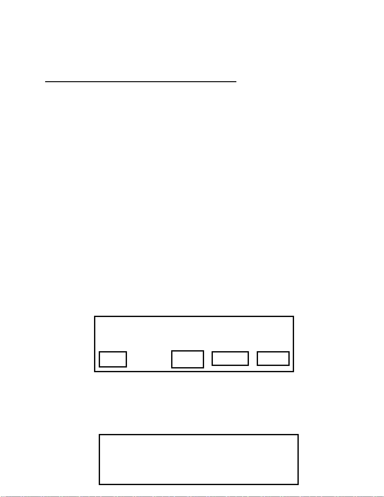
EP6 CONTROL MENU LAYOUT
MAIN SKYE
MENU
DISPLAY
REFRIGERANT SELECTED
AUTO RECOVER VACUUM
BUTTON BAR
MENU
5
MENU 2 SKYE
CHARGE NCG
REFRIGERANT SELECTED
RECOVERED
OIL DRAIN
BUTTON BAR
CHANGE
MENU
3
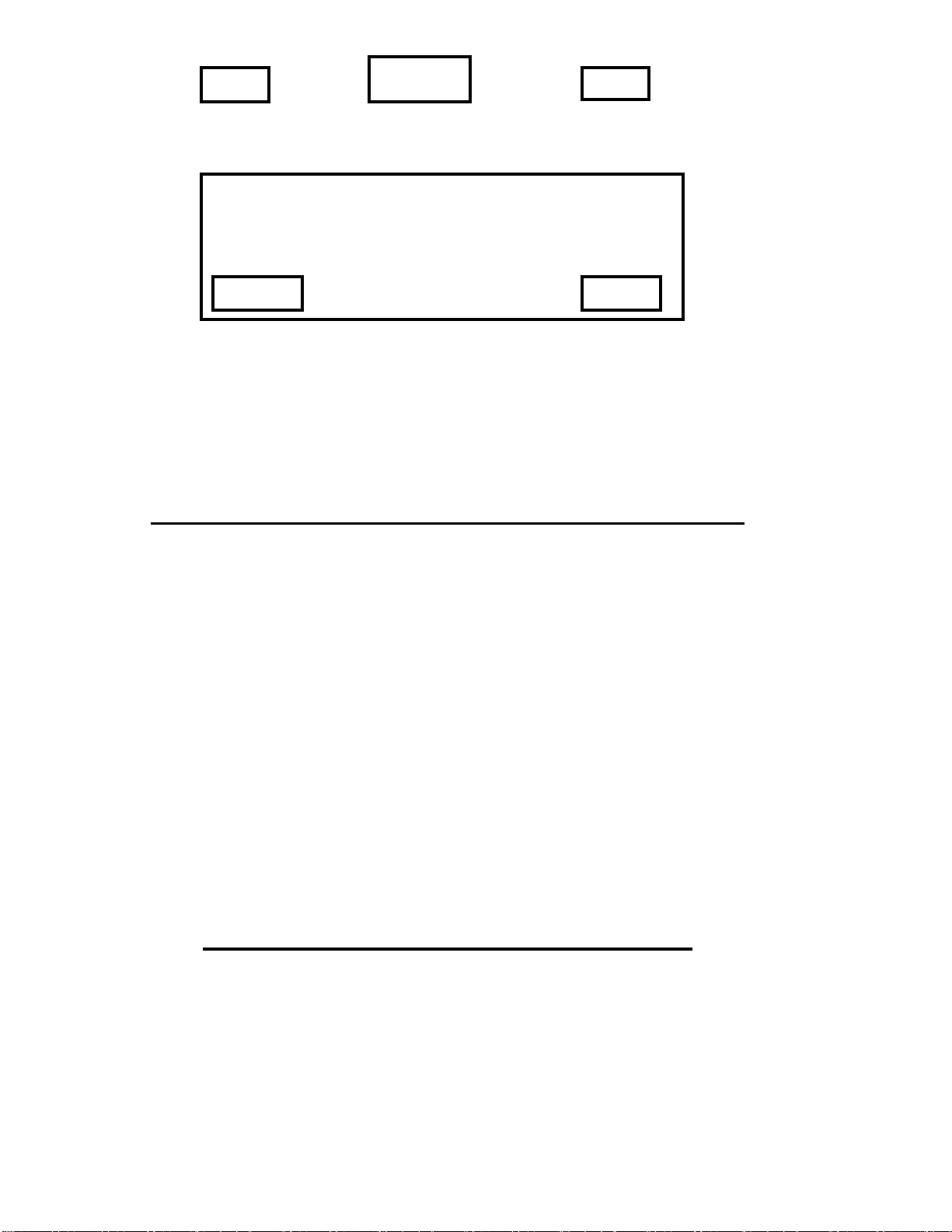
MENU 3
CHANGE
FILTER
REFRIGERANT SELECTED
SKYE
SET
UP
FLUSH HELP MENU
BUTTON BAR
4
MENU 4 SKYE
REFRIGERANT SELECTED
5
6
DISPLAY
TANK
SYSTEM
BUTTON BAR
UPDATE
MAIN
HOSE CONNECTION LAYOUT
LOW
SIDE
HIGH
SIDE
TANK
LIQUID
TANK
VAPOR
MOISTURE
INDICATOR
#
R134a
#
R134a
#
R134a
#
R134a
#
#
R12
#
R12
NOTE: PORTS MAY BE REVERSED TOP TO BOTTOM
#
R12
#
R12
WORKING DISPLAY
Tank Wgt ___ lbs _____ oz FUNCTION %
Full
______ ______ _______ ___
LO PRESS HI PRESS SYS PRESS Clutch
VDC
____
____ ____ ____ TIME
Duct Amb Sys
EXIT
Set Up Procedure
6
7
BEFORE OPERATING YOUR SUPERSKYE MACHINE FOR THE FIRST TIME READ THE
INSTRUCTION MANUAL THEN COMPLETE THE FOLLOWING PROCEDURES.
Your new EP6 must be prepared for use prior to any operation with refrigerant. Follow the
steps in the SET UP selection from MENU 3. This procedure can be used once at the time of
initial set up. It will be deactivated at completion of set up.
THE DEFAULT REFRIGERANT FOR SET UP IS R134a.
1. Fill the vacuum pump reservoir with 4 ounces of the oil provided by unscrewing the vent
cap/dipstick assembly and pouring it into the fill tube. Add an additional 4 ounces after the
motor starts in step 6 then replace the cap/dipstick assembly.
2. Determine which refrigerant you are going to use for the initial set up of the machine then
select the appropriate storage tank. Connect the appropriate short hoses to the tank and
machine (vapor to vapor/liquid to liquid), place the tank on the scale platform, open both
tank valves then connect the tank float lead.
3. Connect the machine to power and turn the master power switch ON. Select MENU 4 then
press the TANK SIZE button and select the tank size you are using (default is 30 lb.).
Return to MENU 4 and press the DISPLAY MODE button. The next screen allows you to
select your preferred weight (lbs & oz or Kg), pressure (PSI, KPa or mBAR) and
temperature (Fahrenheit or Celsius) measurements to be displayed. Press the desired
button for each option, select your desired measurement method then press the EXIT
button to return to the main option screen. Repeat as necessary to select your preferred
methods (default is lbs/oz, PSI and Fahrenheit). Once the measurement selection is
completed, press EXIT to return to the main menu. Press the MENU button to return to
MENU 3 and press the SET UP button.
a. If you are setting up for R134a, connect the tank hoses to the corresponding machine
and tank ports ( VAPOR to VAPOR/LIQUID to LIQUID ) and open both tank valves.
b. If you are setting up for R12, PRESS and HOLD the CHANGE GATE button and
move the access gate manually then connect the tank hoses to the corresponding
machine and tank ports ( VAPOR to VAPOR/LIQUID to LIQUID ) and open both tank
valves.
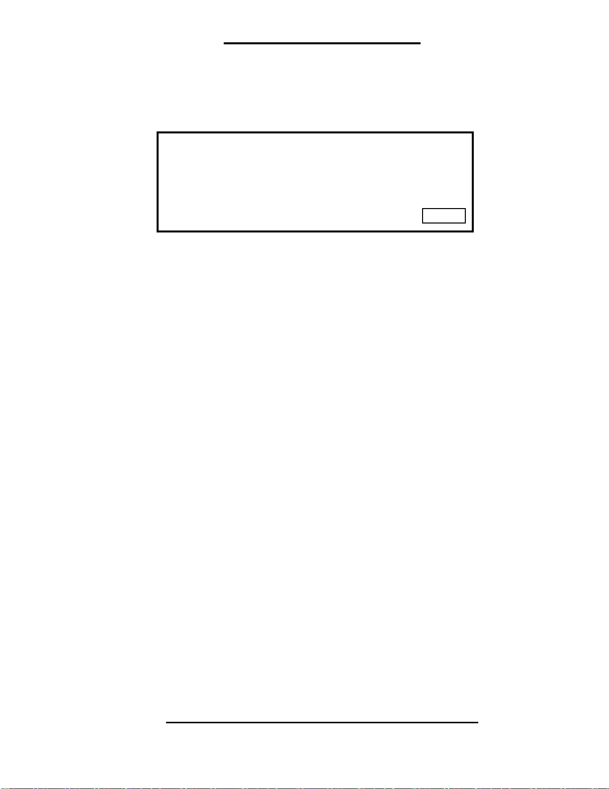
DISPLAY
MODE
DEFAULT SET UP IS R134a
PRESS AND HOLD CHANGE GATE
BUTTON TO MOVE GATE
CHANGE
GATE
CONTINUE EXIT
4. Press the CONTINUE button then press the R12 or R134a button on the following screen to
confirm the refrigerant selected. You have the option to move the gate again at this time.
CONFIRM GATE POSITION FOR
REFRIGERANT SELECTED
7
R134a
CHANGE
GATE
R12
5. When the button for the desired refrigerant is pushed, the next screen will be displayed.
CONTINUE EXIT
CONNECT TANK
OPEN TANK VALVES
REFRIGERANT ________
6. Press the CONTINUE button to initiate the automatic preparation sequence. DO NOT
interrupt this sequence. The service hoses may be connected to the machine while this
operation is in process.
7. When the set up cycle is completed, the machine will stop and display the MAIN MENU.
The set up function is now inoperative and cannot be used again. Your storage tank must
be precharged now.
8
PRECHARGE / RECHARGE STORAGE TANK
IMPORTANT: Be sure that new tanks are in a vacuum before charging.
1. To precharge / recharge the tank with R134a, close the tank liquid valve and remove the
short liquid hose from the tank and machine. Connect the R134a liquid hose to the low
side service hose port on the machine and a virgin R134a bottle, open the valve on the
virgin bottle, turn it upside down and set it in front of the machine.
To precharge / recharge the tank with R12, close the liquid valve on the storage tank and
leave the hose connected to the tank and machine. Connect the R12 low side service hose
to the virgin R12 bottle, open the valve on the virgin bottle, turn it upside down and set it in
front of the machine.
2. Press the RECOVER button and allow the machine to recover at least 7 lbs. of refrigerant
into the storage tank. When the desired amount of refrigerant is precharged, close the
valve on the virgin bottle and allow the machine to shut off automatically.
3. When done precharging / recharging with R134a, return the short liquid hose to the tank
liquid and machine liquid ports and reinstall the low side service hose.
YOUR EP6 IS NOW READY FOR USE
8
DISPLAY PROCEDURE
_
When DISPLAY is selected the screen will change to the working display. This should be the
first screen used when the machine is connected to an AC system to allow the technician to
determine the A/C system’s condition. This screen allows AC system checks and trouble
shooting with the greater ability to locate and diagnose problems than allowed by normal
gauge set methods.
TANK WEIGHT: Displays the gross weight of the tank.
FUNCTION: Displays RECOVER when recovering and VACUUM when vacuuming.
% FULL: Displays the storage tank % full based on empty weight plus refrigerant.
LO: Displays the low side pressure of the AC system.
HI: Displays the high side pressure of the AC system.
SYS: Displays the internal machine pressure.
CLUTCH: Displays the clutch voltage in DC volts.
TIME: Displays timer in timed functions
DUCT: Displays the temperature reading at the AC system duct when in use.
SYS: Displays the temperature of the refrigerant in the machine and tank.
AMB: Displays the temperature of air around the machine.
EXIT: Return to the main menu or previous screen.
Tank Wgt _____ _____ Function %
lbs oz Full
_____ _____ _____ ___
LO PRESS HI PRESS SYS PRESS Clutch
____
___ ____ _____ TIME
Duct Amb Sys
Empty tank weights: 16 lbs for 30 lb. capacity / 25 lbs for 50 lb. capacity.
Note: This reading will display weight fluctuations when the motor is
running. This will not affect the critical measurements.
VDC
EXIT
9
AUTOMATIC ROUTINE PROCEDURE
9
 Loading...