

Page 1

LIT-0085
WTU-14
User’s Manual
version 1.11
Phonetics, Inc.
Page 2

Every effort has been made to ensure that the information in this
document is complete, accurate and up-to-date. Phonetics, Inc.
assumes no responsibility for the results of errors beyond its control.
Phonetics, Inc. also cannot guarantee that changes in equipment
made by other manufacturers, and referred to in this manual, will
not affect the applicability of the information in this manual.
Copyright © 2004 by Phonetics, Inc. dba Sensaphone
First Edition, version 1.11, January 2005
Written and produced by Phonetics, Inc.
Please address comments on this publication to:
Phonetics, Inc.
901 Tryens Road
Aston, PA 19014
Sensaphone is a registered trademark of Phonetics, Inc.
ii
Page 3

Important Safety Instructions
Your Skymetry WTU-14 has been carefully designed to give you years of safe,
reliable performance. As with all electrical equipment, however, there are a few
basic precautions you should take to avoid hurting yourself or damaging the unit:
• Read the installation and operating instructions in this manual carefully. Be
sure to save it for future reference.
• Read and follow all warning and instruction labels on the product itself.
• To protect the Skymetry WTU-14 from overheating, make sure all openings
on the unit are not blocked. Do not place on or near a heat source, such as a
radiator or heat register.
• Do not use your Skymetry WTU-14 near water, or spill liquid of any kind into
it.
• Be certain that your power source matches the rating listed on the AC power
transformer. If you’re not sure of the type of power supply to your facility,
consult your dealer or local power company.
• Do not allow anything to rest on the power cord. Do not locate this product
where the cord will be abused by persons walking on it.
• Do not overload wall outlets and extension cords, as this can result in the risk
of fire or electric shock.
• Never push objects of any kind into this product through ventilation holes as
they may touch dangerous voltage points or short out parts that could result in
a risk of fire or electric shock.
• To reduce the risk of electric shock, do not disassemble this product, but
return it to Sensaphone Customer Service or another approved repair facility
when any service or repair work is required. Opening or removing covers may
expose you to dangerous voltages or other risks. Incorrect reassembly can
cause electric shock when the unit is subsequently used.
• If anything happens that indicates that your Skymetry WTU-14 is not
working properly or has been damaged, unplug it immediately and follow the
procedures in the manual for having it serviced. Return the unit for servicing
under the following conditions:
1. The power cord or plug is frayed or damaged.
2. Liquid has been spilled into the product or it has been exposed to water.
3. The unit has been dropped, or the enclosure is damaged.
4. The unit doesn’t function normally when you’re following the operating
instructions.
iii
Page 4

CAUTION: To reduce the risk of fire or injury to persons, read and follow these
instructions:
1. Replace the battery only with the same or equivalent type recommended
by the manufacturer.
2. Do not dispose of the battery in a fire. The cell may explode. Check with
local codes for possible special disposal instructions.
3. Do not open or mutilate the battery. Released electrolyte is corrosive and
may cause damage to the eyes or skin. It may be toxic if swallowed.
4. Exercise care in handling battery in order not to short the battery with
conducting materials such as rings, bracelets, and keys. The battery or
conductor may overheat and cause burns.
FCC Requirements
Part 15: This equipment has been tested and found to comply with the limits
for a Class A digital device, pursuant to Part 15 of the FCC Rules. These limits
are designed to provide reasonable protection against harmful interference
when the equipment is operated in a commercial environment. This equipment
generates, uses and can radiate radio frequency energy and, if not installed and
used in accordance with the instructions, may cause harmful interference to radio
communications. Operation of this equipment in a residential area is likely to
cause harmful interference in which case the user will be required to correct the
interference at his own expense.
If you experience trouble with the Skymetry
obtaining service or repairs, please contact:
Phonetics, Inc.
901 Tryens Road
Aston, PA 19014
Phone: 610.558.2700
FAX: 610.558.0222
iv
WTU-14, or you need information on
Page 5

v
Page 6

Skymetry WTU-14 Manual
3 YEAR LIMITED WARRANTY
PLEASE READ THIS WARRANTY CAREFULLY BEFORE USING THE PRODUCT.
THIS LIMITED WARRANTY CONTAINS SENSAPHONE’S STANDARD TERMS AND
CONDITIONS. WHERE PERMITTED BY THE APPLICABLE LAW, BY KEEPING YOUR
SENSAPHONE PRODUCT BEYOND THIRTY (30) DAYS AFTER THE DATE OF DELIVERY,
YOU FULLY ACCEPT THE TERMS AND CONDITIONS SET FORTH IN THIS LIMITED
WARRANTY.
IN ADDITION, WHERE PERMITTED BY THE APPLICABLE LAW, YOUR INSTALLATION
AND/OR USE OF THE PRODUCT CONSTITUTES FULL ACCEPTANCE OF THE TERMS
AND CONDITIONS OF THIS LIMITED WARRANTY (HEREINAFTER REFERRED TO AS
"LIMITED WARRANTY OR WARRANTY"). IF YOU DO NOT AGREE TO THE TERMS AND
CONDITIONS OF THIS WARRANTY, INCLUDING ANY LIMITATIONS OF WARRANTY,
INDEMNIFICATION TERMS OR LIMITATION OF LIABILITY, THEN YOU SHOULD NOT
USE THE PRODUCT AND SHOULD RETURN IT TO THE SELLER FOR A REFUND OF THE
PURCHASE PRICE. THE LAW MAY VARY BY JURISDICTION AS TO THE APPLICABILITY
OF YOUR INSTALLATION OR USE ACTUALLY CONSTITUTING ACCEPTANCE OF THE
TERMS AND CONDITIONS HEREIN AND AS TO THE APPLICABILITY OF ANY LIMITATION
OF WARRANTY, INDEMNIFICATION TERMS OR LIMITATIONS OF LIABILITY.
1. WARRANTOR: In this Warranty, Warrantor shall mean "Dealer, Distributor, and/or
Manufacturer."
2. ELEMENTS OF WARRANTY: This Product is warranted to be free from defects in
materials and craftsmanship with only the limitations and exclusions set out below.
3. WARRANTY AND REMEDY: Three-Year Warranty — In the event that the Product
does not conform to this warranty at any time during the time of three years from original
purchase, warrantor will repair the defect and return it to you at no charge.
This warranty shall terminate and be of no further effect at the time the product is: (1)
damaged by extraneous cause such as fire, water, lightning, etc. or not maintained as
reasonable and necessary; or (2) modified; or (3) improperly installed; or (4) misused;
or (5) repaired or serviced by someone other than Warrantors’ authorized personnel or
someone expressly authorized by Warrantor’s to make such service or repairs; (6) used
in a manner or purpose for which the product was not intended; or (7) sold by original
purchaser.
LIMITED WARRANTY, LIMITATION OF DAMAGES AND DISCLAIMER OF LIABILITY FOR
DAMAGES: THE WARRANTOR’S OBLIGATION UNDER THIS WARRANTY IS LIMITED
TO REPAIR OR REPLACEMENT OF THE PRODUCT, AT THE WARRANTOR’S OPTION
AS TO REPAIR OR REPLACEMENT. IN NO EVENT SHALL WARRANTORS BE LIABLE
OR RESPONSIBLE FOR PAYMENT OF ANY INCIDENTAL, CONSEQUENTIAL, SPECIAL
AND/OR PUNITIVE DAMAGES OF ANY KIND, INCLUDING BUT NOT LIMITED TO ANY
LABOR COSTS, PRODUCT COSTS, LOST REVENUE, BUSINESS INTERRUPTION LOSSES,
LOST PROFITS, LOSS OF BUSINESS, LOSS OF DATA OR INFORMATION, OR FINANCIAL
LOSS, FOR CLAIMS OF ANY NATURE, INCLUDING BUT NOT LIMITED TO CLAIMS
IN CONTRACT, BREACH OF WARRANTY OR TORT, AND WHETHER OR NOT CAUSED
BY WARRANTORS’ NEGLIGENCE. IN THE EVENT THAT IT IS DETERMINED IN ANY
ADJUDICATION THAT THE LIMITED WARRANTIES OF REPAIR OR REPLACEMENT ARE
INAPPLICABLE, THEN THE PURCHASER’S SOLE REMEDY SHALL BE PAYMENT TO THE
PURCHASER OF THE ORIGINAL COST OF THE PRODUCT, AND IN NO EVENT SHALL
WARRANTORS BE LIABLE OR RESPONSIBLE FOR PAYMENT OF ANY INCIDENTAL,
CONSEQUENTIAL, SPECIAL AND/OR PUNITIVE DAMAGES OF ANY KIND, INCLUDING
vi
Page 7

BUT NOT LIMITED TO ANY LOST REVENUE, BUSINESS INTERRUPTION LOSSES, LOST
PROFITS, LOSS OF BUSINESS, LOSS OF DATA OR INFORMATION, OR FINANCIAL
LOSS, FOR CLAIMS OF ANY NATURE, INCLUDING BUT NOT LIMITED TO CLAIMS IN
CONTRACT, BREACH OF WARRANTY OR TORT, AND WHETHER OR NOT CAUSED BY
WARRANTORS’ NEGLIGENCE.
WITHOUT WAIVING ANY PROVISION IN THIS LIMITED WARRANTY, IF A
CIRCUMSTANCE ARISES WHERE WARRANTORS ARE FOUND TO BE LIABLE FOR
ANY LOSS OR DAMAGE ARISING OUT OF MISTAKES, NEGLIGENCE, OMISSIONS,
INTERRUPTIONS, DELAYS, ERRORS OR DEFECTS IN WARRANTORS’ PRODUCTS OR
SERVICES, SUCH LIABILITY SHALL NOT EXCEED THE TOTAL AMOUNT PAID BY THE
CUSTOMER FOR WARRANTORS’ PRODUCT AND SERVICES OR $250.00, WHICHEVER IS
GREATER. YOU HEREBY RELEASE WARRANTORS FROM ANY AND ALL OBLIGATIONS,
LIABILITIES AND CLAIMS IN EXCESS OF THIS LIMITATION.
INDEMNIFICATION AND COVENANT NOT TO SUE: YOU WILL INDEMNIFY, DEFEND
AND HOLD HARMLESS WARRANTORS, THEIR OWNERS, DIRECTORS, OFFICERS,
EMPLOYEES, AGENTS, SUPPLIERS OR AFFILIATED COMPANIES, AGAINST ANY AND
ALL CLAIMS, DEMANDS OR ACTIONS BASED UPON ANY LOSSES, LIABILITIES,
DAMAGES OR COSTS, INCLUDING BUT NOT LIMITED TO DAMAGES THAT ARE
DIRECT OR INDIRECT, INCIDENTAL, SPECIAL OR CONSEQUENTIAL, AND INCLUDING
ATTORNEYS FEES AND LEGAL COSTS, THAT MAY RESULT FROM THE INSTALLATION,
OPERATION, USE OF, OR INABILITY TO USE WARRANTORS’ PRODUCTS AND SERVICES,
OR FROM THE FAILURE OF THE WARRANTORS’ SYSTEM TO REPORT A GIVEN EVENT
OR CONDITION, WHETHER OR NOT CAUSED BY WARRANTORS’ NEGLIGENCE.
YOU AGREE TO RELEASE, WAIVE, DISCHARGE AND COVENANT NOT TO SUE
WARRANTORS, THEIR OWNERS, DIRECTORS, OFFICERS, EMPLOYEES, AGENTS,
SUPPLIERS OR AFFILIATED COMPANIES, FOR ANY AND ALL LIABILITIES POTENTIALLY
ARISING FROM ANY CLAIM, DEMAND OR ACTION BASED UPON ANY LOSSES,
LIABILITIES, DAMAGES OR COSTS, INCLUDING BUT NOT LIMITED TO DAMAGES
THAT ARE DIRECT OR INDIRECT, INCIDENTAL, SPECIAL OR CONSEQUENTIAL, AND
INCLUDING ATTORNEYS FEES AND LEGAL COSTS, THAT MAY RESULT FROM THE
INSTALLATION, OPERATION, USE OF, OR INABILITY TO USE WARRANTORS’ PRODUCTS
AND SERVICES, OR FROM THE FAILURE OF THE WARRANTORS’ SYSTEM TO REPORT
A GIVEN EVENT OR CONDITION, WHETHER OR NOT CAUSED BY WARRANTORS’
NEGLIGENCE, EXCEPT AS NECESSARY TO ENFORCE THE EXPRESS TERMS OF THIS
LIMITED WARRANTY.
EXCLUSIVE WARRANTY: THE LIMITED WARRANTY OR WARRANTIES DESCRIBED
HEREIN CONSTITUTE THE SOLE WARRANTY OR WARRANTIES TO THE PURCHASER.
ALL IMPLIED WARRANTIES ARE EXPRESSLY DISCLAIMED, INCLUDING: THE
WARRANTY OF MERCHANTABILITY AND THE WARRANTY OF FITNESS FOR A
PARTICULAR USE AND THE WARRANTY OF FITNESS FOR A PARTICULAR PURPOSE
AND THE WARRANTY OF NON-INFRINGEMENT AND/OR ANY WARRANTY ARISING
FROM A COURSE OF DEALING, USAGE, OR TRADE PRACTICE.
It must be clear that the Warrantors are not insuring your premises or business or
guaranteeing that there will not be damage to your person or property or business if
you use this Product. You should maintain insurance coverage sufficient to provide
compensation for any loss, damage, or expense that may arise in connection with the
use of products or services, even if caused by Warrantors’ negligence. The warrantors
assume no liability for installation of the Product and/or interruptions of the service due
to strikes, riots, floods, fire, and/or any cause beyond Seller’s control, further subject
to the limitations expressed in any License Agreement or other Agreement provided by
Warrantors to purchaser.
vii
Page 8

Skymetry WTU-14 Manual
The agreement between the Warrantors and the Purchaser, including but not limited to the
terms and conditions herein shall not be governed by the Convention for the International
Sale of Goods. Where applicable, the Uniform Commercial Code as adopted by the State
of Delaware shall apply.
4. PROCEDURE FOR OBTAINING PERFORMANCE OF WARRANTY: In the event that the
Product does not conform to this warranty, the Product should be shipped or delivered
freight prepaid to a Warrantor with evidence of original purchase.
5. LEGAL REMEDIES AND DISCLAIMER: Some jurisdictions may not allow, or may place
limits upon, the exclusion and/or limitation of implied warranties, incidental damages
and/or consequential damages for some types of goods or products sold to consumers
and/or the use of indemnification terms. Thus, the exclusions, indemnification terms and
limitations set out above may not apply, or may be limited in their application, to you. If
the implied warranties can not be excluded, and the applicable law permits limiting the
duration of implied warranties, then the implied warranties herein are to be limited to the
same duration as the applicable written warranty or warranties herein. The warranty or
warranties herein may give you specific legal rights that will depend upon the applicable
law. You may also have other legal rights depending upon the law in your jurisdiction.
6. CHOICE OF FORUM AND CHOICE OF LAW: In the event that a dispute arises out of or
in connection with this Limited Warranty, then any claims or suits of any kind concerning
such disputes shall only and exclusively be brought in either the Court of Common Pleas
of Delaware County, Pennsylvania or the United States District Court for the Eastern
District of Pennsylvania.
Regardless of the place of contracting or performance, this Limited Warranty and all
questions relating to its validity, interpretation, performance and enforcement shall be
governed by and construed in accordance with the laws of the State of Delaware, without
regard to the principles of conflicts of law.
viii
Effective date May 1, 2004
PHONETICS, INC. d.b.a. SENSAPHONE
901 Tryens Road
Aston, PA 19014
Phone: 610.558.2700 Fax: 610.558.0222
www.sensaphone.com
Page 9

Table of Contents
TABLE OF CONTENTS
Important Safety Instructions . . . . . . . . . . . . . . . . . . . . iii
FCC Requirements . . . . . . . . . . . . . . . . . . . . . . . . . . . .
iv
WARRANTY . . . . . . . . . . . . . . . . . . . . . . . . . . . . .vi
Chapter 1: Introduction
Features . . . . . . . . . . . . . . . . . . . . . . . . . . . . . . . . . . 16
Skymetry WTU-14 Diagram . . . . . . . . . . . . . . . . . . . .
Overview
Web Page Initialization . . . . . . . . . . . . . . . . . . . . .
Data Message Usage
Technical Support
. . . . . . . . . . . . . . . . . . . . . . . . . . . . . . . . . 18
. . . . . . . . . . . . . . . . . . . . . . . . . . . 19
. . . . . . . . . . . . . . . . . . . 15
17
18
. . . . . . . . . . . . . . . . . . . . . .18
Chapter 2: Installation . . . . . . . . . . . . . . . . . . . 21
Operating Environment . . . . . . . . . . . . . . . . . . . . . . . 21
Activating your Skymetry WTU-14 . . . . . . . . . . . . . . .
Mounting the Skymetry WTU-14 (Aluminum Housing)
Mounting the Skymetry WTU-14 (NEMA-4X Housing) .
Locking the NEMA 4X Enclosure . . . . . . . . . . . . . . .
Antenna Information . . . . . . . . . . . . . . . . . . . . . . . . .
21
21
23
24
25
Connecting the Power Supply
Connecting a Battery . . . . . . . . . . . . . . . . . . . . . . . . .
Grounding . . . . . . . . . . . . . . . . . . . . . . . . . . . . . .27
Wiring Sensors to Dry Contact Inputs . . . . . . . . . . . . .
Normally Closed Sensors . . . . . . . . . . . . . . . . . . . .
Normally Open Sensors . . . . . . . . . . . . . . . . . . . . .
Wiring Sensors to Analog Inputs
Wiring Recommendations
LED Indicators . . . . . . . . . . . . . . . . . . . . . . . . . . . . . .
. . . . . . . . . . . . . . . . . . 25
. . . . . . . . . . . . . . . . 31
. . . . . . . . . . . . . . . . . . . . . 33
26
28
29
30
34
ix
Page 10

Skymetry WTU-14 Manual
Chapter 3: Software Installation . . . . . . . . . . . . . 35
Installing and Starting the Software . . . . . . . . . . . . . . 35
Installation . . . . . . . . . . . . . . . . . . . . . . . . . . . . . .35
Activating your Skymetry WTU-14 . . . . . . . . . . . . . . .
36
Connecting Locally
Skymetry WTU-14 Web Page
. . . . . . . . . . . . . . . . . . . . . . . .36
. . . . . . . . . . . . . . . . . . 38
Chapter 4: Input Programming . . . . . . . . . . . . . 39
Alarm States . . . . . . . . . . . . . . . . . . . . . . . . . . . . . . . 39
Dry Contact Inputs . . . . . . . . . . . . . . . . . . . . . . . . . . .
Dry Contact
Programming . . . . . . . . . . . . . . . . . . . . . 41
Configuring the Input Name . . . . . . . . . . . . . . . . . .
Input Enable/Disable . . . . . . . . . . . . . . . . . . . . . . .
Configuring the Input Type . . . . . . . . . . . . . . . . . . .
Configuring the Run Timer
Configuring the Pulse Counter
. . . . . . . . . . . . . . . . . . .42
. . . . . . . . . . . . . . . .42
Alarm Enable/Disable . . . . . . . . . . . . . . . . . . . . . .
Alarm on Return-to-Normal . . . . . . . . . . . . . . . . . . .
Alarm Recognition Time . . . . . . . . . . . . . . . . . . . . .
Alarm Reset Time
. . . . . . . . . . . . . . . . . . . . . . . . .43
Analog Inputs . . . . . . . . . . . . . . . . . . . . . . . . . . . . . .
Analog Inputs
Programming . . . . . . . . . . . . . . . . . . . 44
40
42
42
42
43
43
43
43
Configuring the Input Name . . . . . . . . . . . . . . . . . .
Configuring the Input Type . . . . . . . . . . . . . . . . . . .
Input Enable/Disable . . . . . . . . . . . . . . . . . . . . . . .
Setting Table Limits
. . . . . . . . . . . . . . . . . . . . . . . .45
Calibration . . . . . . . . . . . . . . . . . . . . . . . . . . . . . .45
Alarm Enable/Disable . . . . . . . . . . . . . . . . . . . . . .
Alarm on Return-to-Normal . . . . . . . . . . . . . . . . . . .
Setting the Alarm Limits
. . . . . . . . . . . . . . . . . . . . .46
Alarm Recognition Time . . . . . . . . . . . . . . . . . . . . .
x
44
45
45
45
46
46
Page 11

Table of Contents
Alarm Reset Time . . . . . . . . . . . . . . . . . . . . . . . . .46
Power Input . . . . . . . . . . . . . . . . . . . . . . . . . . . . .
Battery Input
Special Function Inputs
. . . . . . . . . . . . . . . . . . . . . . . . . . . .47
. . . . . . . . . . . . . . . . . . . . . . . 47
46
Chapter 5: Output Programming . . . . . . . . . . . . 49
Setting the Output Name . . . . . . . . . . . . . . . . . . . . . . 50
Configuring the Output Operating Mode
Switching the Output . . . . . . . . . . . . . . . . . . . . . . . . .
Output Status & Statistics . . . . . . . . . . . . . . . . . . . . . .
. . . . . . . . . . 50
51
51
Chapter 6: Pump Control . . . . . . . . . . . . . . . . . 53
How it works—Float Switches . . . . . . . . . . . . . . . . . . 53
How it works—Analog Level Sensor
Installation Recommendations
Programming for Pump Control . . . . . . . . . . . . . . . . .
Output Wiring . . . . . . . . . . . . . . . . . . . . . . . . . . . . . .
. . . . . . . . . . . . . . . . . . 55
. . . . . . . . . . . . . 55
55
57
Chapter 7: Machine-to-Machine Control . . . . . . . 59
Local Output Control . . . . . . . . . . . . . . . . . . . . . . . . . 60
Important Information and Warnings . . . . . . . . . . . . .
Sample Application . . . . . . . . . . . . . . . . . . . . . . . . . .
61
61
Chapter 8: Alarm Notification . . . . . . . . . . . . . . 65
How does notification work . . . . . . . . . . . . . . . . . . . . 65
Voice Phone Call . . . . . . . . . . . . . . . . . . . . . . . . . . . .
Internet E-Mail . . . . . . . . . . . . . . . . . . . . . . . . . . . . . .
Alphanumeric Pager
Text Messaging to Cell Phones . . . . . . . . . . . . . . . . . .
Acknowledgment via E-mail or Text Message . . . . . . .
Additional Information
. . . . . . . . . . . . . . . . . . . . . . . . . 69
. . . . . . . . . . . . . . . . . . . . . . . 74
66
67
71
74
xi
Page 12

Skymetry WTU-14 Manual
Chapter 9: Operation . . . . . . . . . . . . . . . . . . . . 75
PART ONE: Alarm Notification and Acknowledgment . 75
Alarm Recognition . . . . . . . . . . . . . . . . . . . . . . . . .
Alarm Notification . . . . . . . . . . . . . . . . . . . . . . . . .
Dialout Note: Call Progress
Alarm Notification—Voice
Alarm Notification—
Alarm Notification—Alphanumeric Pager . . . . . . . . .
Alarm Notification—Text Message to Cell Phone
Tier Delay . . . . . . . . . . . . . . . . . . . . . . . . . . . . . . . . .
Alarm Acknowledgment
Alarm Acknowledgment—Voice Notification
Alarm Acknowledgment—Alphanumeric Pager . . . . .
Alarm Acknowledgment—Text Message to Cell Phone
Alarm Acknowledgment—
PART TWO: Status Request . . . . . . . . . . . . . . . . . . . . .
E-mail . . . . . . . . . . . . . . . . . . .76
. . . . . . . . . . . . . . . . . .75
. . . . . . . . . . . . . . . . . . .76
. . . . . . . . . . . . . . . . . . . . . . 78
. . . . . .78
Automatic . . . . . . . . . . . .80
75
75
77
. . .77
77
79
.79
81
Chapter 10: Skymetry Web Page . . . . . . . . . . . . 83
Status Refresh . . . . . . . . . . . . . . . . . . . . . . . . . . . . . . 83
Programming Refresh
. . . . . . . . . . . . . . . . . . . . . . . . 84
Programming via the Web Page
Switching Outputs via the Web page . . . . . . . . . . . . .
Account Usage
Alarm History . . . . . . . . . . . . . . . . . . . . . . . . . . . . . .
. . . . . . . . . . . . . . . . . . . . . . . . . . . . . 85
. . . . . . . . . . . . . . . . 84
84
85
Chapter 11: Testing the Skymetry WTU-14 . . . . . 87
Notification Testing . . . . . . . . . . . . . . . . . . . . . . . . . . 87
Input Testing . . . . . . . . . . . . . . . . . . . . . . . . . . . . . . .
Output Testing . . . . . . . . . . . . . . . . . . . . . . . . . . . . . .
Control Programming
Pump Control
xii
. . . . . . . . . . . . . . . . . . . . . . . . . . . . . . 89
. . . . . . . . . . . . . . . . . . . . . . . . 88
87
88
Page 13

Table of Contents
APPENDIX A: Checking Your Skymetry WTU-14
for Proper Operation . . . . . . . . . . . . . . . . . 91
APPENDIX B: Troubleshooting
APPENDIX C: Thermistor Table . . . . . . . . . . . . . .
APPENDIX D: SKYMETRY WTU-14 Specifications
APPENDIX E: Replacing the Backup Battery
APPENDIX F: Optional
Accessories . . . . . . . . . . 105
APPENDIX G: Returning Your Skymetry WTU-1
. . . . . . . . . . . . . . 93
99
. 101
. . . 103
4
for Repair . . . . . . . . . . . . . . . . . . . . . . . . . 107
Test Log . . . . . . . . . . . . . . . . . . . . . . . . . . . . . .
109
Index . . . . . . . . . . . . . . . . . . . . . . . . . . . . . . . 111
xiii
Page 14

Skymetry WTU-14 Manual
xiv
Page 15

Chapter 1: Introduction
Chapter 1: Introduction
Congratulations on your purchase of the Skymetry WTU-14 by
Phonetics, Inc.
The WTU-14 Wireless Telemetry Unit is a powerful monitoring,
alarm, and control system. Its built-in wireless technology means
you won’t need a telephone line to communicate with the unit. It
can monitor and control your environment and equipment using
eight dry contact inputs, six analog inputs, built-in power failure
detection, and two relay outputs. It can perform simplex or duplex
alternating pump control using a level transducer or float switches.
The unit can also perform machine-to-machine control among mul
tiple WTU-14 devices. Up to 8 machine-to-machine control algo
rithms can be configured per device so that input conditions on one
Skymetry WTU-14 can logically control outputs on another using
simple, fill-in-the-blank, comparison programming. The unit fea
tures several communication options including: voice telephone call,
e-mail, and text messaging. You can also request a status report
from most two-way text devices, like alphanumeric pagers and
cell phones. The Skymetry WTU-14 is fully programmable via the
included Skymetry Software package for Windows or through the
unit’s web page at www.skymetry.com.
-
-
-
The WTU-14 will produce a web page of input and output status
and alarm history that can be viewed at www.skymetry.com. You
can also program the unit or control outputs from the web page.
The Skymetry is the ultimate choice for remote monitoring and
control where telephone lines are non-existent or too expensive.
Applications include pump houses, cable TV huts, remote equip
-
ment rooms, and tower light monitoring.
On the front of the unit are LED indicators to show the operat
ing status (Power, Battery OK, In-Range, Registered, Alarm, and
Outputs). All programming is stored in nonvolatile memory so that
all programming is retained even without power. The unit will per
form alarm event logging of the 14 inputs, power, and battery to the
Skymetry web page. A complete status report of all monitored con
-
15
Page 16

Skymetry WTU-14 Manual
ditions can be retrieved via e-mail for viewing on a computer or text
messaging device. The Skymetry.com web page can be updated on
demand to allow viewing of the current conditions at the site from
any internet-connected computer. The unit comes in an aluminum
housing with mounting tabs and is optionally available in a plastic
NEMA-4X enclosure with a 36-hour battery backup.
Features
• 8 Dry Contact Inputs: NO, NC, Pulse Count, Equipment RunTime
• 6 Analog Inputs: 10K Thermistor (temperature), or 4–20mA
• 2 Relay Outputs: 20 different automatic and manual modes
• Local Logic Control
• Machine-to-Machine Control among Skymetry units
• Duplex and Simplex Pump Control
• Wireless Alarm Message Delivery via Voice, E-mail, or text
message.
• Status & Programming via web page
• NEMA 4X enclosure and Battery Backup (optional)
• Low Power consumption—suitable for solar operation
Solar Kit available (Part No. FGD-0062)
16
Page 17

Skymetry WTU-14 Diagram
Chapter 1: Introduction
1. Antenna
2. LEDs
3. Terminal blocks
4. RS-232 DCE
5. Jumpers for Temperature or 4–20mA settings
17
Page 18

Skymetry WTU-14 Manual
Overview
When installing and programming a Skymetry WTU-14 there are
several steps required for all installations. Listed below are those
required for a typical installation and start-up of the Skymetry
WTU-14.
1) Confirm wireless coverage for the installation site.
2) Select a wireless messaging plan and activate the unit.
3) Install the unit, set the input jumpers, and wire the sensors.
4) Go online locally and program the unit.
5) Wait for the web page to initialize and become active.
6) Verify status on the web site.
7) Test all sensors and alarm notification—see Chapter 11: Testing
the Skymetry WTU-14
Web Page Initialization
Your Skymetry WTU-14 is accessible via the internet at www.
skymetry.com. From the web page you can view status, make
programming changes, and even control outputs. Before any of
these features can be utilized, the unit must first initialize the web
server. This happens automatically immediately after your f irst local
programming session with the unit. As soon as you disconnect from
your first programming session the unit will begin to update the
web server with all of its programming. This may take an hour or
two depending on how many parameters were programmed. During
this initialization period it is recommended that the unit remain
powered on and no additional programming changes take place. For
detailed information on the Skymetry web page see Chapter 10.
Data Message Usage
Your Skymetry WTU-14 communicates over the wireless network
using data messages. These are transmitted whenever an alarm mes
sage is delivered, machine-to-machine command is sent, or a web
update is requested. The number of data messages used for each
type of transmission is shown below in the table:
18
-
Page 19

Chapter 1: Introduction
Alarm Message to Voice or E-mail 1–4
Alarm Message to Web Server
Alarm Acknowledgement
Programming Parameter Read or Write
Machine-to-Machine Command
Status Refresh to the Web Page
Programming Refresh to the Web Page 9 to 115
The last item, Programming Refresh to the web, depends on how
many changes were made since the last update. Only items that have
changed will be sent. Typically, once the unit has been programmed,
additional programming changes are minimal. However, if you were
to completely reprogram the unit and change every parameter, then
the maximum number of data messages would be transmitted.
Technical Support
This instruction manual will help you install and program the
Skymetry WTU-14 properly. Be sure to read it completely before
beginning the installation process. If there are any questions or
problems that arise upon installation or operation, please contact our
Technical Support team:
1
1
2
1
5–7
PHONETICS, INC.
901 Tryens Road
Aston, PA 19014
Phone: 610.558.2700
FAX: 610.558.0222
19
Page 20

Skymetry WTU-14 Manual
20
Page 21

Chapter 2: Installation
Chapter 2: Installation
Operating Environment
The Skymetry WTU-14 should be mounted and operated in a
clean, dry environment. The unit must communicate to the wireless
network, so care must be taken not to install the unit inside a metal
cabinet or other location that will prevent the unit from receiving
a radio signal unless the antenna can be relocated to a location
free of obstruction. The unit is microprocessor-controlled and, as
a result, should not be installed near devices that generate strong
electromagnetic fields. Such interference is typically generated by
power switching equipment such as motors, contactors, or variable
frequency drives. Where this is unavoidable, mount the unit in a
separate, grounded steel enclosure with an external antenna (see
Appendix F: Accessories). A poor operating environment may result
in unwanted system resets and/or system lockup. The temperature
range the unit can operate in is -20°F to 158°F (-29°C to 70°C).
Activating your Skymetry WTU-14
Your Skymetry device must be activated on the wireless network
before you can send or receive messages
gramming is performed for the first time.
To activate your Skymetry WTU-14 device, fill out the activation
form included with the package and follow the instructions, or con
tact your sales representative with the device serial number.
Your Skymetry WTU-14 is activated when the “In Range” and
“Registered” LEDs are lit.
and before any local pro-
Mounting the Skymetry WTU-14 (Aluminum Housing)
Locate a suitable mounting location for the WTU-14 that provides
good radio reception and convenient wiring to your equipment and
power. If you will be connecting high voltages to the outputs, con
-
-
21
Page 22

Skymetry WTU-14 Manual
sider placing the unit inside of a cabinet for safety. Use a plastic
or fiberglass cabinet to minimize the signal loss on radio reception.
When installing the unit inside of a metal cabinet, be sure to use an
external antenna as the metal will shield the unit from receiving a
radio signal.
On the top and bottom of the housing are mounting holes to attach
the unit to either a panel or wall. The mounting surface should be
sturdy enough to support 2 lbs.
The unit should be mounted using four #10-32 bolts where appro
priate, or four #10 tapping screws. (The screw kit for the Skymetry
WTU-14 includes (4) #10-32 screws, (4) #10-32 nuts, and (4) #10
lockwashers). When mounting the unit to a wall, make sure the
mounting screws fully engage a solid member (for example, a stud)
of the support structure. Mount the Skymetry WTU-14 in an upright
position so that you can easily connect wires to the terminal strips.
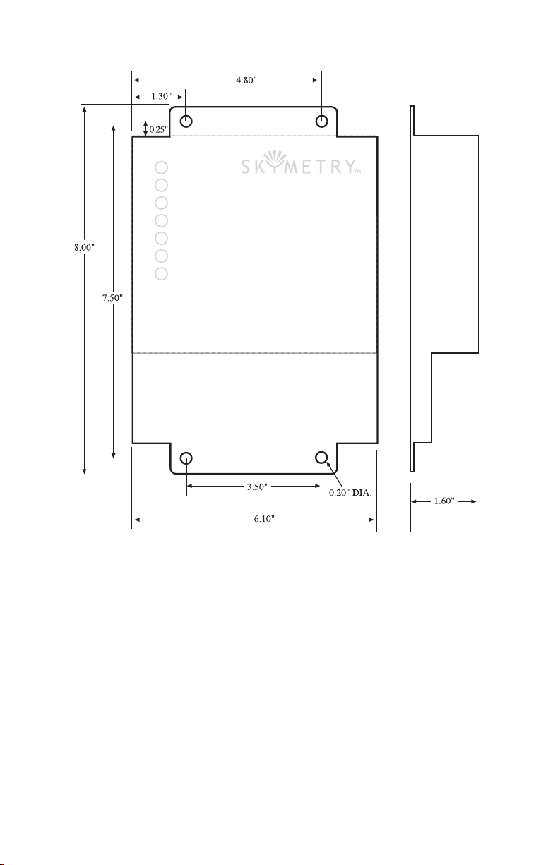
The dimensions of the enclosure are: 8.0" x 6.1" x 1.6". See Figure 1.
22
Page 23
Chapter 2: Installation
Figure 1: Skymetry mounting
Mounting the Skymetry WTU-14 (NEMA-4X Housing)
Locate a suitable mounting location for the Skymetry WTU-14
enclosure that provides good radio reception and convenient wiring
to your equipment and power. On the top and bottom of the hous
ing are mounting tabs to attach the unit to a wall. The mounting
surface should be sturdy enough to support 10 lbs. The unit should
be mounted using four #10-32 bolts where appropriate, or four #10
tapping screws. (The screw kit for the WTU-14 includes (4) #10-32
screws, (4) #10-32 nuts, and (4) #10 lockwashers). When mount
ing the unit to a wall, make sure the mounting screws fully engage a
-
-
23
Page 24
Skymetry WTU-14 Manual
solid member (for example, a stud) of the support structure. Mount
the WTU-14 in an upright position so that you can easily connect
wires to the terminal strips. The dimensions of the NEMA-4x enclo
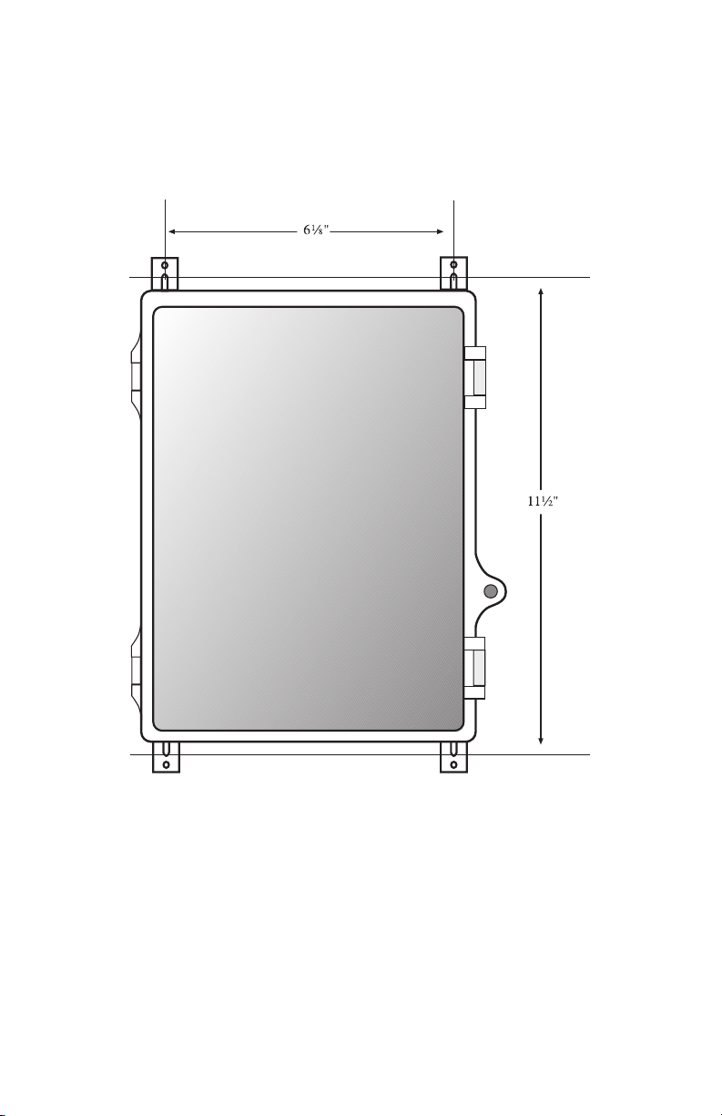
sure are: 12.1" x 8.0" x 5.5". See Figure 2.
-
Figure 2: NEMA-4 Mounting diagram
Locking the NEMA 4X Enclosure
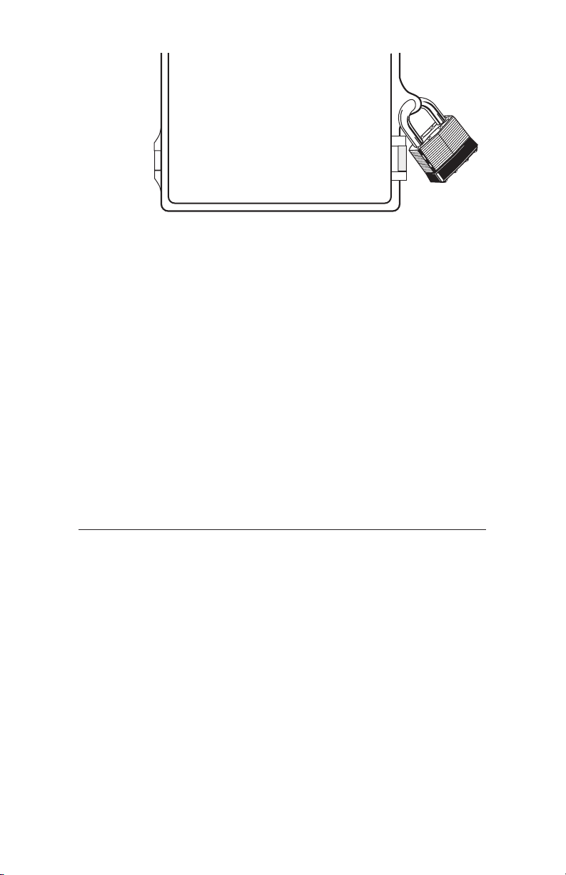
The Skymetry WTU-14 enclosure can be locked by installing
a small padlock through the loop on the front door of the
enclosure. See Figure 3.
24
Page 25
Chapter 2: Installation
Figure 3: Locking the NEMA-4x enclosure
Antenna Information
The Skymetry WTU-14 comes with a unity-gain stub antenna
designed specifically for the frequency range required. In order
to comply with FCC RF exposure, the external antenna must be
mounted in a location where people will never come within 20cm of
the antenna. The gain of the antenna may not exceed 0dBi. For opti
mum antenna performance, there should be no metal objects within
close proximity of the antenna.
-
WARNING Do not over-tighten the antenna on the
Skymetry WTU-14; this may cause
permanent dam-
age to the device.
The antenna must be connected before the device is powered up.
Connecting the Power Supply
The Skymetry WTU-14 requires a 15VDC 800mA power supply
(part number FGD-8250) to operate. This power supply will charge
an external 12V battery (2–12AH) and provide the necessary power
to transmit messages over the wireless network.
WARNING: Do not substitute supplies with lower
capacity.
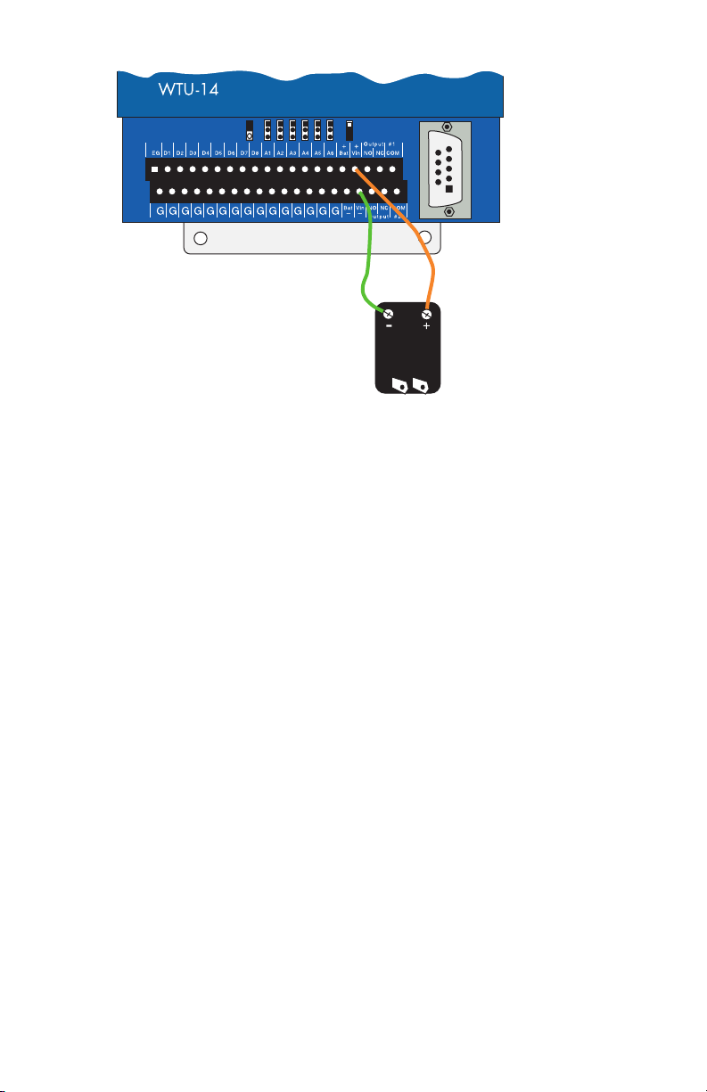
Connect the positive terminal of the Power Supply to the +Vin ter
minal on the Skymetry WTU-14.
Connect the negative terminal of the Power Supply to the -Vin ter
minal on the Skymetry WTU-14.
-
-
25
Page 26
Skymetry WTU-14 Manual
Figure 4: Power Supply Wiring
Connecting a Battery
In the event of a power failure, the Skymetry WTU-14 can operate from a 12V sealed lead-acid gel-cell rechargeable battery. The
duration of battery time depends on the capacity of the battery (see
chart below). The unit incorporates circuitry to maintain the proper
charge for a 12V gel-cell battery whenever the power supply is
plugged in. The unit also includes special circuitry to prevent the
battery from being damaged in the event of an extended power out
age. The battery should provide approximately 5 years of service
before needing replacement.
-
Battery Backup
Capacity (AH) Time (hrs)
2.2 36
3.0 50
5.0 80
8.0 120
12.0 200
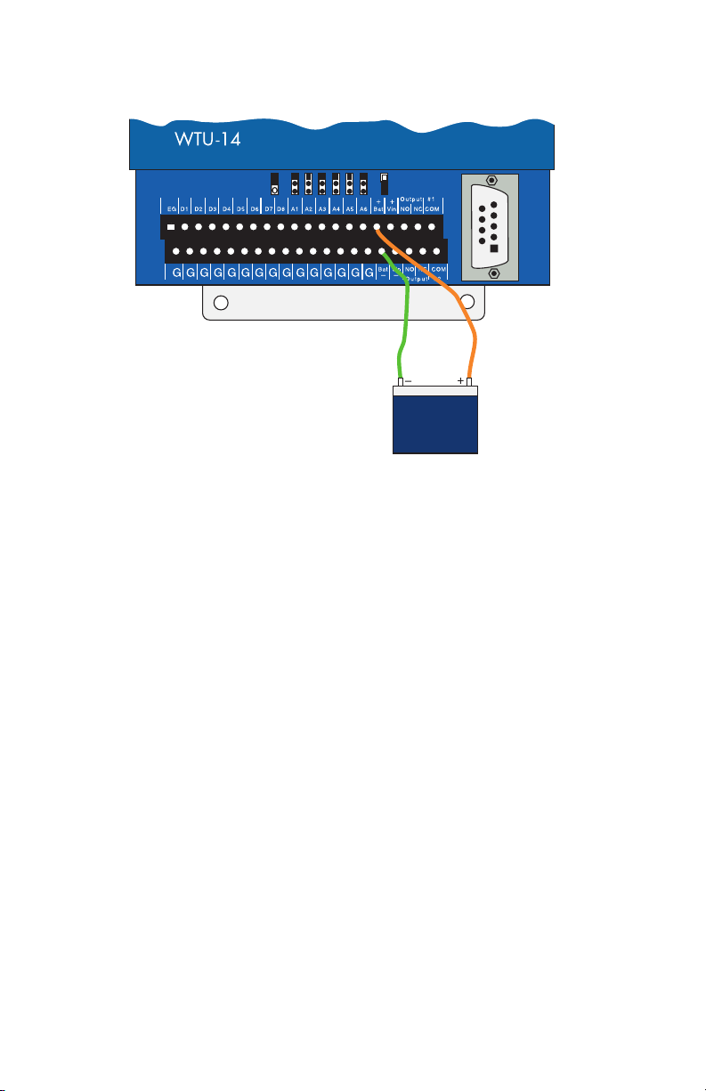
Connect the positive terminal of the Battery to the
on the Skymetry WTU-14.
26
+ Bat terminal
Page 27
Chapter 2: Installation
Connect the negative terminal of the Battery to the – Bat terminal
on the Skymetry WTU-14.
Figure 5: Battery connection
The battery is considered low at 12.0V and the Battery LED will
blink at this voltage level. If main power is less than 7.0V and the
battery voltage reaches 11V, the battery LED will go out and the
unit will go into hibernation mode (a low-power mode in which the
unit shuts down). The unit will return to its regular operating mode
when either the main power is restored or the battery voltage rises
above 11.5V. If the battery voltage continues to fall below 10.5V, the
unit will disconnect the battery to prevent deep discharge damage to
the battery. The unit will not reconnect the battery until the battery
voltage rises above 12.5V.
Grounding
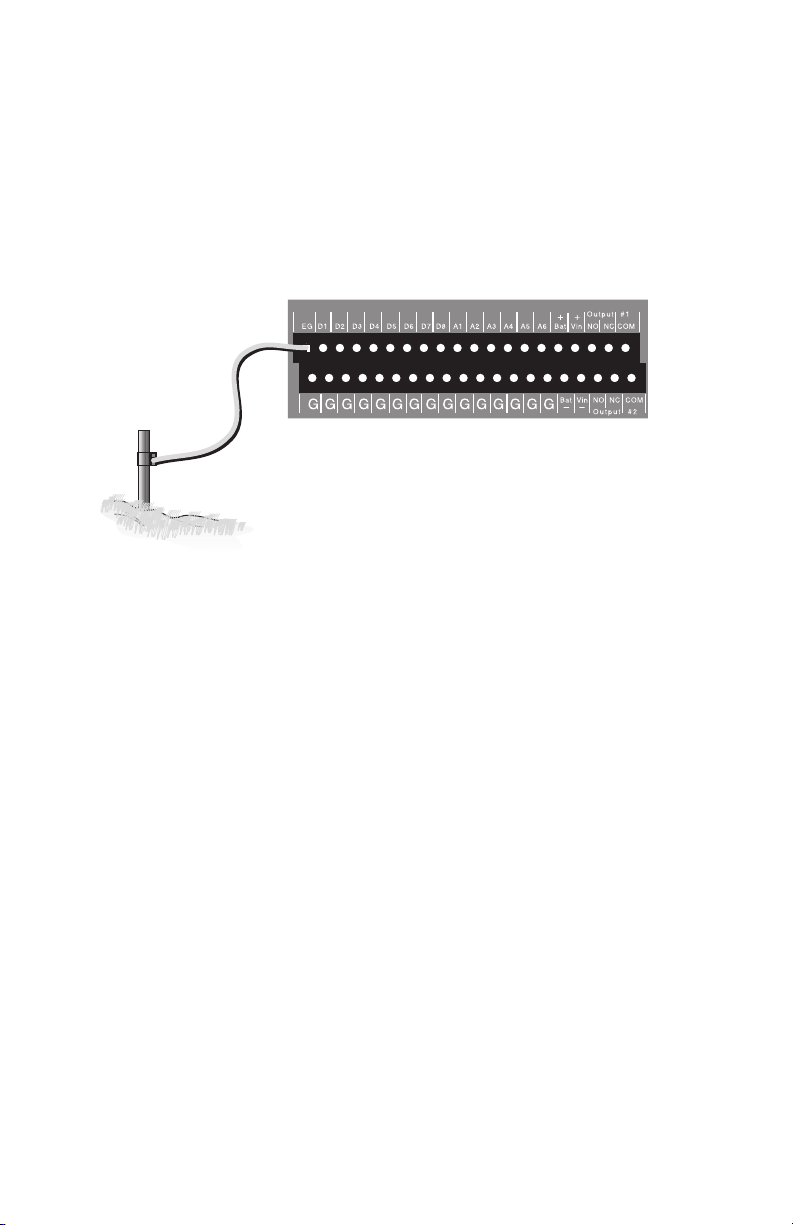
Connect a #14AWG copper wire to the earth ground terminal
(marked “EG”) on the left end of the terminal strip and connect the
other end to a ground rod or metal cold water pipe (See Figure 6). It
is extremely important that the earth ground connection be as short
as possible. The ground rod should have sufficient depth to provide
a low impedance connection to earth. This connection is required
for the surge/lightning protection circuits to function properly.
27
Page 28
Skymetry WTU-14 Manual
NOTE: Proper earth grounding of the Skymetry
WTU-14 is required for warranty coverage.
Ground rods can typically be found at local electrical supply houses
and/or hardware stores. You MUST contact your state “Call before
you dig” hotline at least two days before you install your ground
rod, to insure that it is safe to install the ground rod in a chosen
area.
Figure 6: Grounding the Skymetry
Wiring Sensors to Dry Contact Inputs
The WTU-14 has 8 Dry Contact inputs that can be used to monitor Normally Open (N.O.) or Normally Closed (N.C.) sensors. In
addition, they can also be used for pulse counting and equipment
run-time accumulation. When used for pulse count or run time
functions, the unit will count the pulse (or accumulate time) when
the input changes to the opposite of its normal state.
Dry contact sensors are wired to the terminals labeled D1 through
D8. The corresponding Ground terminals are located on the lower
level terminal strip. The input type is programmed within the
Skymetry Software.
WARNING: Do not use sensors, switches, or relays
that supply any voltage or current to the Skymetry
WTU-14.
28
Page 29

Chapter 2: Installation
Figure 7: Sensor connected to a dry contact input]
Any N.O. or N.C. sensor can be attached to the WTU-14 using 18–
24 gauge wire. For distances of 1000' or more, use heavier gauge
wire. When running wire outdoors it is recommended that shielded
cable be used. Connect the shield to a good earth ground or metallic
cold water pipe. The total resistance of the circuit cannot be greater
than 100 ohms. Use wire appropriate for the application. See the
wire length recommendations, later in this chapter.
The WTU-14 may have more than one sensor connected to the same
terminal, however, the normal condition for each sensor on the same
terminal must be identical (either all N.O. or all N.C.).
Normally Closed Sensors
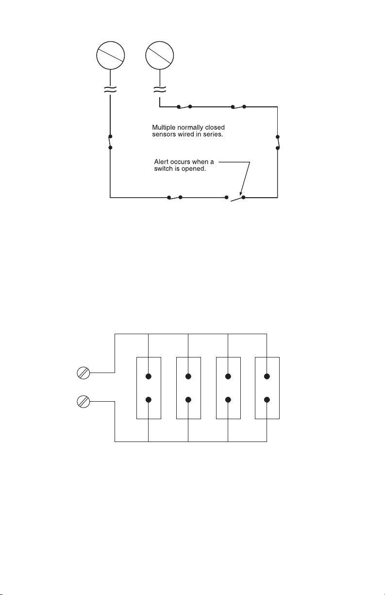
To wire more than one normally closed sensor on one input, they
must be connected in series. Connect a lead from the first sensor to
one of the Dry Contact Inputs on the terminal strip. Next, take the
other lead from the first sensor and connect it to one lead from the
next sensor. Continue connecting sensors end-to-end until you have
connected all of your sensors. Take the second lead from your last
sensor and connect it to the ground screw on the WTU-14 terminal
strip. See Figure 8.
Multiple N.C. inputs are typically magnetic reed switches to moni
tor the security of windows and doors.
-
29
Page 30
Skymetry WTU-14 Manual
Figure 8: Connecting multiple N.C. sensors to one input terminal
Normally Open Sensors
To wire several normally open sensors to one Dry Contact input,
connect them in parallel. To do this, take one lead from each sen
sor and attach it one of the Dry Contact Input terminals. Then take
the second lead from each sensor and attach it to the corresponding
ground terminal. See Figure 9.
-
Figure 9: Connecting multiple N.O. sensors to one input terminal
30
Page 31
Chapter 2: Installation
Wiring Sensors to Analog Inputs
The WTU-14 has 6 Analog inputs that can be used to monitor 10K
Thermistors (temperature) or 4–20mA transducers. Analog trans
ducers are wired to the terminals labeled A1 through A6. The cor
responding Ground terminals are located on the lower level terminal
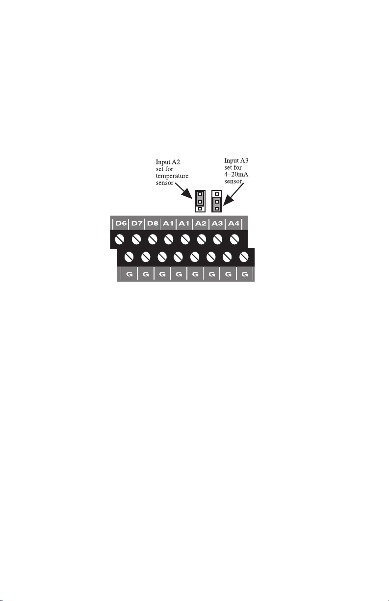
strip. The input must be configured by setting the corresponding
jumper in either the Temperature or 4–20mA position. See figure
below:
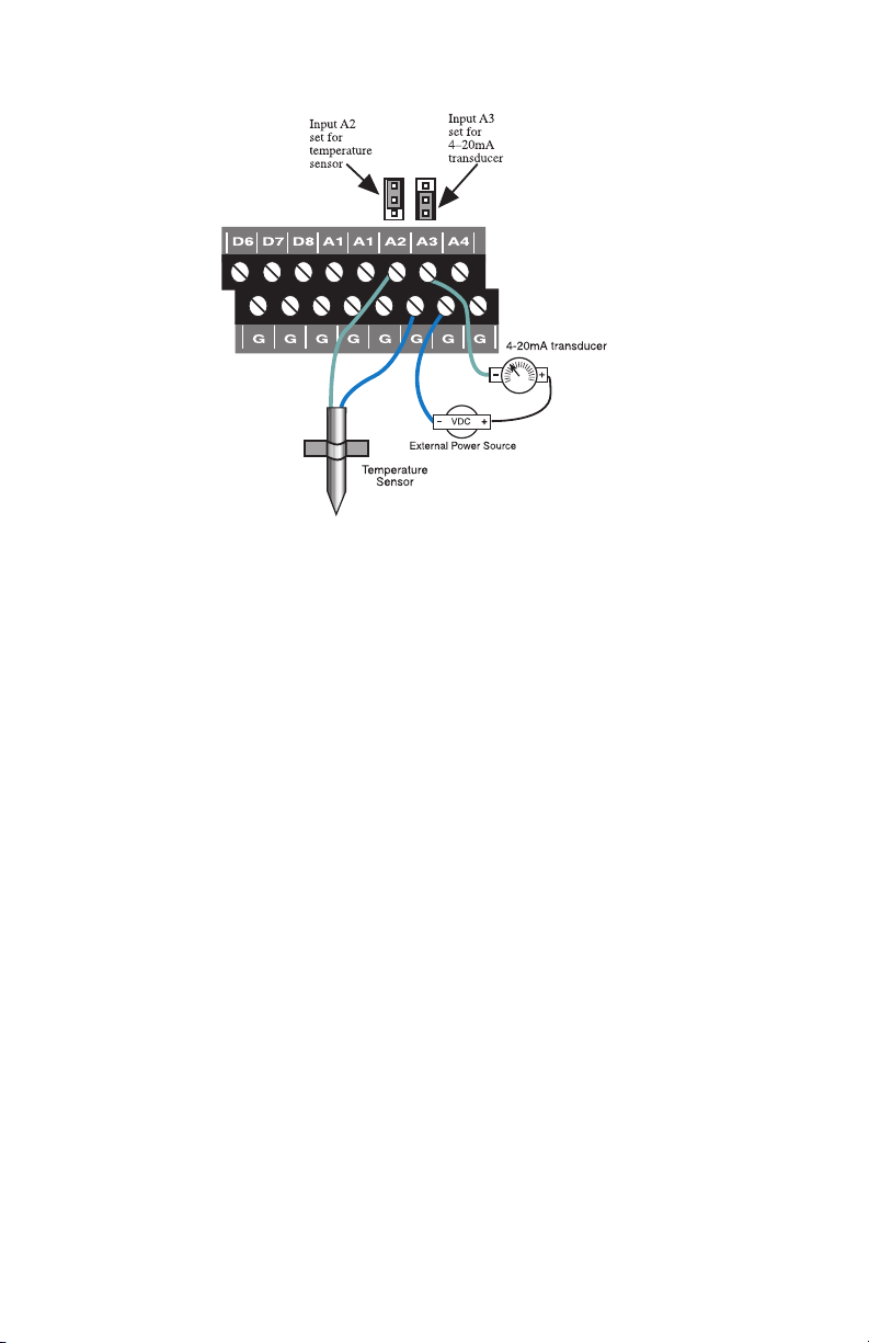
Figure 10: Input A2 configured for temp, A3 configured for 4-20mA
-
-
Temperature: The unit will accept 10K thermistors. These should be
wired to an Analog Input terminal and the adjacent ground termi
nal. For compatible thermistors check the accessory list or thermis
-
tor data in the appendices. 10K Thermistor temperature range: -60ºF
to 175ºF (-51ºC to 79ºC).
4–20mA: A 4–20mA transducer requires you to have an external
DC power supply for the transducer. Connect the positive wire of
your transducer to the positive terminal of your DC power supply.
Connect the negative terminal of the transducer to an Analog Input
terminal on the Skymetry WTU-14. Connect the negative terminal
from your power supply to the adjacent ground terminal on the
WTU-14.
31
Page 32
Skymetry WTU-14 Manual
Figure 11: A thermistor and a 4–20mA transducer connected to the unit
32
Page 33
Chapter 2: Installation
Wiring Recommendations
The Skymetry WTU-14 will work fine in indoor environments
using unshielded cable. When wiring will be subject to long lengths
(>100') or if run outdoors, it is highly recommended that shielded
cable be used and that the shield be connected to an earth ground.
This is particularly important for sensor wires that are run in con
duit with other noise-generating conductors, such as 60Hz AC. It is
strongly recommended that input wiring be run in a conduit separat
ed from AC power or output wiring. When wire runs are long or are
in close proximity to large power consuming, power generating, or
power switching equipment, it is highly recommended that shielded
wire be used.
-
-
Also, be sure to use the appropriate gauge wire based on the dis
tance and sensor type. See chart below:
Wire Gauge Thermistor NO/NC Contact & 4–20mA
#24 250' 1000'
#22 500' 2000'
#20 1000' 4000'
#20 1000' 4000'
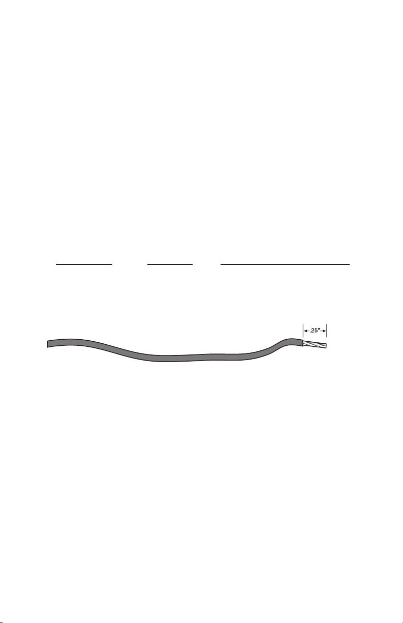
When preparing wire for connection to the terminal blocks, strip
of insulation from the conductor (see figure below).
Figure 12: Wire stripped for connection
NOTE: All wiring should comply with Section 17
of the UL requirements.
-
1
⁄4"
33
Page 34

Skymetry WTU-14 Manual
LED Indicators
The LEDs provide on-site alarm and status information. Listed
below are descriptions of how the LEDs work.
ALARM:
LED Off: No alarms
LED Blinking: Unacknowledged alarm exists
LED On: Acknowledged alarm exists
REGISTERED:
LED Off: Not registered (unit not activated)
LED Blinking: Skymetry is sending or receiving messages
LED On: Registered
IN RANGE:
LED Off: Not in range of wireless network
LED On: In range of wireless network
BATTERY OK:
LED Off: No Battery
LED Blinking: Battery condition low
LED On: Battery OK
POWER OK:
LED Off: Power is Off
LED Blinking slow: Power very low (unit hibernating)
LED Blinking fast: Power is low
LED On: Power is OK
OUTPUT #1:
LED Off: Output Relay #1 is off.
LED On: Output Relay #1 is on.
OUTPUT #2:
LED Off: Output Relay #2 is off.
LED On: Output Relay #2 is on.
34
Page 35

Chapter 3: Software Instllation
Chapter 3: Software Installation
This section describes how to install and conf igure the Skymetry
WTU-14 Programming Software for your computer.
Installing and Starting the Software
Minimum requirements:
• 486 or better computer (Pentium recommended)
• 4 MB of free disk space
• 16 MB RAM (32 MB RAM recommended)
• CD-ROM drive
• Graphics card compatible with Microsoft Windows 98, NT,
2000, or XP (such as VGA)
• Microsoft Windows™ 98, NT, 2000, or XP
• VGA or Super VGA monitor
• Mouse
• Serial Port
Installation
The Skymetry WTU-14 Programming Software is easy to install.
Make sure that all Windows applications are closed before attempt
ing to run Setup. If you encounter problems during installation,
please call Phonetics Technical Support at 610-558-2700. The
Skymetry Software will install to a directory named C:\Program
Files\Skymetry, unless you choose to change the directory name.
1. Start Windows.
2. Insert the Skymetry CD-ROM. The installation program should
run automatically. Follow the prompts as directed.
If the software does not install automatically, then click the Windows
Start button, and select Run, then type in d:\setup.exe. Click OK.
Follow the prompts as directed.
3. Reboot your computer when the installation is complete.
-
35
Page 36
Skymetry WTU-14 Manual
Activating your Skymetry WTU-14
Your Skymetry device must be activated on the wireless network
before you can send or receive messages
and before any local pro-
gramming is performed for the first time.
To activate your Skymetry WTU-14 device, fill out the activation
form included with the package and follow the instructions, or con
tact your sales representative with the device serial number.
Your Skymetry WTU-14 is activated when the “In Range” and
“Registered” LEDs are lit.
Note: The Registered LED will blink when the
Skymetry is sending or receiving messages.
Connecting Locally
The Skymetry Software will allow you to connect with the unit to
view status and program it. First, connect a serial cable to a serial
port on your computer. Connect the other end to the 9-pin RS-232
connector on the Skymetry WTU-14. Run the Skymetry Software.
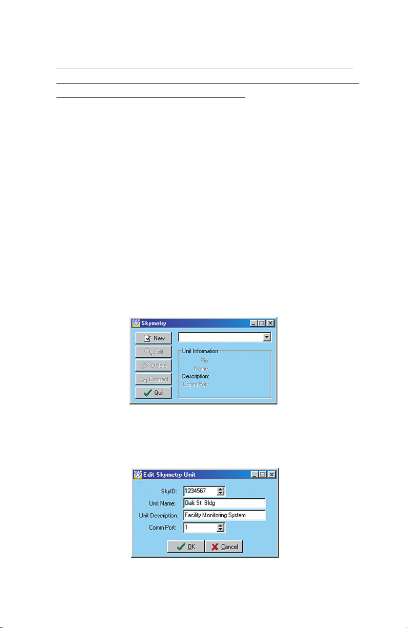
The following screen will appear.
-
Figure 1: First-Run Unit Information form
Click the New button to set-up a new WTU-14 unit. The Edit
Skymetry Unit screen will appear (see below).
Figure 2: Edit Skymetry Unit
36
Page 37
Chapter 3: Software Instllation
Enter the SkyID, Name, Description, and Comm Port settings for
this unit. The unit Name can be up to 16 characters, the Description
can be up to 30 characters. Click
ton and the software should connect and start downloading the pro
OK. Now click the Connect but-
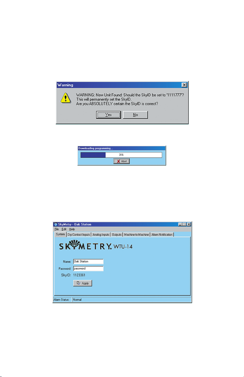
gramming from the unit. If this is the first time, you will have to
enter the SkyID. A warning message will appear to prompt you.
Figure 3: SkyID Warning message
Figure 4: Programming Download in progress
If this was a new unit (factory default settings) the Name you
entered on the edit screen will automatically be copied into the unit.
After downloading the programming, the main Skymetry WTU-14
window will appear (see below).
Figure 5: Main Skymetry Window: System Tab
This is a good time to enter a Password. The Password, while not
required for local access, is required for all remote communication.
The password can be up to 8 characters. Click Apply when finished.
37
Page 38

Skymetry WTU-14 Manual
Skymetry WTU-14 Web Page
You can view status and change settings in your Skymetry WTU-14
via the internet. This makes it possible to manage your unit from
anywhere in the world. See Chapter 10 for detailed information on
using the web page.
How it works
When the Skymetry WTU-14 is installed you should perform all
programming via the local serial port. You must set the password.
After you disconnect from the unit, the WTU-14 will begin to ini
tialize the status and programming information on the Skymetry.
com web page. This may take one to two hours depending on the
number of programming parameters changed and the response time
of the wireless network. Take care not to make additional program
ming changes until the web initialization has finished. To view
status or make programming changes via the web page, go to www.
skymetry.com and enter your SkyID and Password
Note that the unit keeps track of programming items that have
changed so that each time the Programming Refresh Link is clicked,
only the changed items are sent. To get just the current status, you
should click the Status Refresh Link. This will retrieve the latest
input status from your unit. It will take a few minutes for this pro
cess to execute.
.
-
-
-
Note: Each time you click the Status or
Programming Refresh links, data will be sent to and
from your WTU-14 unit. This will use data mes
sages. Once you exceed your data message limit,
additional charges will apply.
38
Page 39

Chapter 4: Input Programming
Chapter 4: Input Programming
The Skymetry WTU-14 features 8 dry contact inputs and 6 analog inputs. The analog inputs are configurable as temperature or
4–20mA. The contact inputs can be used with Normally Open (NO)
or Normally Closed (NC) sensors. The analog inputs can be used
with 10K thermistors for temperature monitoring (available from
Phonetics) or any 4–20 mA transducer. The monitored temperature
range is -60° to 175° F (-51° to 79° C). Programmable table values
can be entered when using 4–20mA transducers to scale the reading
to the appropriate units of measure.
Note: It is highly recommended that if you make
any programming changes locally (at the unit via
the serial port) after your web page has been initial
ized, that you click the Programming Refresh Link
on the web page soon thereafter. This is to ensure
that the information you are viewing on the web
page is up to date. This will also ensure that the
alarm log information displayed on the web page is
accurate.
-
Alarm States
Each Dry Contact or Analog input is monitored based on the programming parameters that define the input type and the alarm limits
for each input. Based on this programming all inputs will always
be in one of four Alarm States: Normal, Alarm, Unacknowledged
Alarm, or Normal-Unacknowledged. Each of these alarm states is
defined below:
Normal” alarm state means that an input is either:
A “
a) Within the programmed alarm limits.
b) A Normally Open input is open, or a Normally Closed input is
closed.
c) An input is beyond its limits or is opposite of its pro
grammed normality, but has not yet met its programmed alarm
Recognition Time
.
-
39
Page 40

Skymetry WTU-14 Manual
An input that is in an “Alarm” state means that:
a) The selected input is currently beyond its programmed alarm
limits or is opposite of its programmed normality.
b) The selected input has exceeded the programmed recognition
time.
c) The alarm has been acknowledged.
An input that is in an “Unacknowledged Alarm” state means that:
a) The selected input is currently beyond its programmed alarm
limits or is opposite of its programmed normality.
b) The selected input has exceeded the programmed recognition
time.
c) The alarm has not been acknowledged.
An input that is in a “
Normal but Unacknowledged” state means
that:
a) The selected input is within its programmed alarm limits.
b) A Normally Open input is open, or a Normally Closed input is
closed.
c) A prior alarm on the selected input has not yet been acknowl
edged.
Dry Contact Inputs
The 8 dry contact inputs can be programmed for normally open
(NO) or normally closed (NC) operation. In addition, you can have
the Skymetry WTU-14 count the number of times the input changes
state (pulse count) and maintain the amount of time that the input is
in the opposite state (Run Time). Click on the Dry Contact Tab to
display the main status screen.
-
40
Page 41
Chapter 4: Input Programming
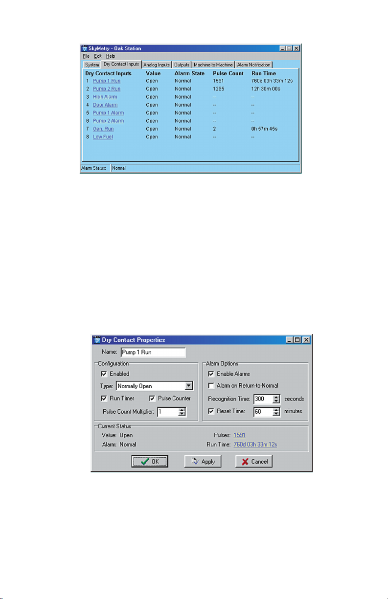
Figure 1: Dry Contact tab
This screen displays the current status of all 8 dry contact inputs.
If any of the inputs were in alarm the Alarm State column would
display the word “Alarm.” If the alarm was unacknowledged, the
Alarm State would say “Alarm;Unack” and a button would appear
at the bottom of the screen to acknowledge the alarm.
Dry Contact Programming
Click the input name to bring up the properties screen for the selected input. The following screen will appear:
Figure 2: Dry Contact properties
If a dry contact changes from its Normal state to the opposite state
for the duration of the programmed recognition time, the input will
go into alarm. Note that it must be a continuous change to be recog
-
41
Page 42

Skymetry WTU-14 Manual
nized as an alarm. Once an alarm trips, the unit will begin its notification sequence (unless you are online through the serial port, in
which case you can acknowledge the alarm directly and cancel the
notification process). Listed below are definitions for each of the
parameters for programming the dry contact inputs.
Configuring the Input Name
The input Name is used to describe the condition being monitored.
It can be up to 16 characters.
Input Enable/Disable
A channel must be Enabled for the input to be read by the WTU-14.
When a channel is enabled its status will appear on the status screen
and on the web page.
Configuring the Input Type
The input Type can be either Normally Open or Normally Closed.
When an input changes from its normal condition to the opposite
condition, the Pulse Count (if enabled) will increment, the Run
Timer (if enabled) will start running, and the Alarm Recognition
timer will start running (if alarms are enabled).
Configuring the Run Timer
The Run Timer can be used to track how long an input condition has
existed. This can be useful for monitoring pump or generator run
times. The value can be preset by clicking on the run time value on
the lower right part of the screen.
Configuring the Pulse Counter
The Pulse Counter can be used to track how many times a contact
closure has changed state. Other possibilities include: measuring
rainfall from a tipping bucket rain gauge or measuring liquid flow
from a pulsed output flow gauge. The maximum value of the Pulse
Counter (after the multiplier is applied) is 2 billion. Minimum Pulse
Width for Pulse Count: 50ms.
The Pulse Count Multiplier allows you to make each pulse equate to
a greater value. For example, suppose a flow gauge outputs a single
pulse for every 100 gallons. By setting the Pulse Count Multiplier
42
Page 43

Chapter 4: Input Programming
to 100 the Pulse Count value now becomes the actual total number
of gallons measured by the gauge. The range of values for the Pulse
Count Multiplier is 1 to 65,535.
Alarm Enable/Disable
The Enable Alarms checkbox activates the alarm processing func-
tions for the selected channel. When the input exceeds the the pro
grammed alarm limits and exceeds the programmed recognition
time the notification process begins.
-
Alarm on Return-to-Normal
The Skymetry WTU-14 has the capability to notify you when an
input (that had previously gone into alarm) returns to normal. When
checked, Alarm on Return-to-Normal initiates this notification.
Alarm Recognition Time
The Recognition Time is the time required for a fault condition to
qualify as an alarm event. The sensor/channel must remain beyond
the limits or in a fault condition continuously for this entire period
of time in order to become an alarm. The range of values is 0–
32,767 seconds.
Alarm Reset Time
The Reset Time is the time allowed for an acknowledged alarm’s
fault condition to be corrected before the Skymetry WTU-14 resets
(reactivates) the alarm and begins the message delivery process all
over again. The minimum reset time is 30 minutes, the maximum is
32,767 minutes.
Analog Inputs
The 6 analog inputs can be programmed for 10K thermistor (temperature in degrees Fahrenheit or Celsius) or 4–20mA transducer.
The Skymetry WTU-14 will maintain the minimum and maximum
values reached for each channel. When 4–20mA is selected you
can enter table low and high values to correlate the 4mA and 20mA
signals to actual values for your application. Click on the Analog
Inputs Tab to display the main status screen.
43
Page 44
Skymetry WTU-14 Manual
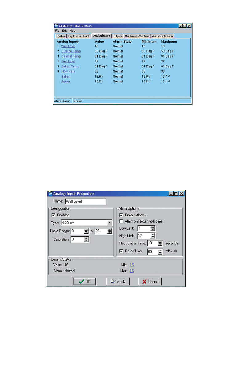
Figure 3: Analog Inputs tab
This screen displays the current status of all 6 analog inputs. If any
of the inputs were in alarm the Alarm State column would display
the word “Alarm.” If the alarm was unacknowledged the Alarm
State would say “Alarm Unack” and a button would appear at the
bottom of the screen to acknowledge the alarm.
Analog Inputs Programming
Figure 4: Analog Inputs Properties
Configuring the Input Name
The input Name is used to describe the condition being monitored.
It can be up to 16 characters.
44
Page 45

Chapter 4: Input Programming
Configuring the Input Type
The input Type can be temperature 10K(deg F), temperature 10K
(deg C), or 4–20mA. Select the type to match your sensor.
Note: Be sure to put the input jumper in the correct
position.
Input Enable/Disable
A channel must be Enabled for the input to be read by the Skymetry
WTU-14. When a channel is enabled its status will appear on the
status screen and on the web page. Select the type of analog input
from the pulldown menu.
Setting Table Limits
When 4–20mA is selected, you can enter table low and high values
to correlate the 4mA and 20mA signals to actual values for your
application. For example, suppose you’re using a 4–20mA transduc
er to measure the depth of water in a 15 foot well. Simply enter a
Table Low value of 0 and a Table High value of 15 and the WTU-14
will scale the input to read between 0 and 15 feet.
Programmable range
Table Low/High: -16,334 to 16,333
Default settings
Table Low value: 0
Table High value: 100
-
Calibration
To compensate for minor variances in sensor accuracy, an offset
may be programmed for each analog input. For example, if the
above input were sensing temperature and was reading 3 degrees too
low, then the calibration would be set at 3 as shown above, to obtain
an accurate reading. Only Analog-type inputs can be
calibrated.
Alarm Enable/Disable
The Enable Alarms checkbox activates the alarm processing func-
tions for the selected channel. When the input exceeds the the pro
grammed low or high alarm limits and exceeds the programmed
recognition time the notification process begins.
-
45
Page 46

Skymetry WTU-14 Manual
Alarm on Return-to-Normal
The WTU-14 has the capability to notify you when an input (that
had previously gone into alarm) has returned to normal, that is,
returns to within the programmed alarm limits. When checked,
Alarm on Return-to-Normal initiates this notification.
Setting the Alarm Limits
Each analog input has a programmable Low and High Alarm limit.
When the input value goes beyond the programmed alarm limits for
the duration of the recognition time, the WTU-14 will go into alarm
and initiate the alarm notification process.
Programmable range
Table Low/High: -16,334 to 16,333
Default settings
Table Low value: 0
Table High value: 100
Alarm Recognition Time
The Recognition Time is the time required for a fault condition to
qualify as an alarm event. The sensor/channel must remain beyond
the programmed limits continuously for this entire period of time in
order to become an alarm. The range of values is 0–32,767 seconds.
Alarm Reset Time
The Reset Time is the time allowed for an acknowledged alarm’s
fault condition to be corrected before the WTU-14 resets (reacti
vates) the alarm and begins the message delivery process all over
again. The minimum reset time is 30 minutes, the maximum is
32,767 minutes.
Power Input
Power monitoring is a built-in function. The unit will go into alarm
when the power level drops below 11.75V for the programmed rec
ognition time. In this state the Power LED will blink.
46
-
-
Page 47

Chapter 4: Input Programming
Battery Input
Battery monitoring is a built-in function. The unit will go into alarm
when the battery level drops below 12.0V for the programmed rec
ognition time. In this state the Battery LED will blink.
Special Function Inputs
When the Skymetry WTU-14 is used for Pump Control, several of
the inputs are dedicated to a specific task depending on whether
Dry Contact or Analog Level is selected as the Pump Control
method. The tables below identify which inputs are used and what
function they serve. Refer to the Pump Control chapter for more
information.
Dry Contact Fill/Drain Pump Control
Dry Contact Input #6 – Lead pump float switch
Dry Contact Input #7 – Lag pump float switch
Dry Contact Input #8 – All pumps off float switch
Analog Level Fill/Drain Pump Control
Analog Input #6 – connect to analog (4–20mA) level sensor
-
47
Page 48

Skymetry WTU-14 Manual
48
Page 49
Chapter 5: Output Programming
Chapter 5: Output Programming
The Skymetry WTU-14 has two relay outputs capable of switching
up to 0.3A at 120VAC, or 1.0A at 24VDC. The outputs can be con
trolled in a number of ways both automatically and manually. Some
examples are listed below:
n Each relay can be manually turned on or off through the PC
software or via the WTU-14 web page.
n Either relay can be set to turn on when a particular alarm
occurs.
n Either relay can be set to turn on when any alarm occurs.
n Either relay can be set to turn on when any digital or any analog
alarm occurs.
n One or both relays can be programmed to operate in pump con-
trol mode (simplex/duplex) for fill or drain applications.
-
n A relay can be controlled automatically based on Dry Contact
or Analog input values using greater-than, less-than, or equal-to
statements (See Chapter 7: Machine-to-Machine Control).
n A relay may also be controlled by another Skymetry unit using
machine-to-machine control. This allows the Skymetry WTU-14
to be used for distant pump/well control applications.
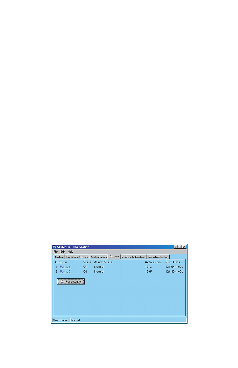
Figure 1: Outputs tab
49
Page 50
Skymetry WTU-14 Manual
Setting the Output Name
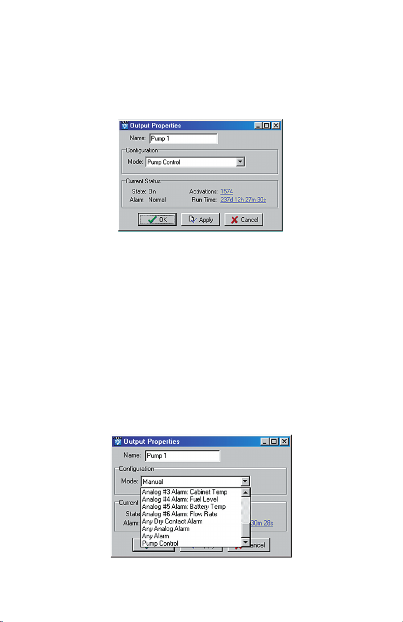
To set up the relay outputs, click on the Outputs tab. Next, click on
the Name for Output 1 (blue) to bring up the Output 1 Properties
screen. Enter a name for the output which describes the device that
the output will be controlling.
Figure 2: Output Properties screen
Configuring the Output Operating Mode
Click the drop-down arrow and select the operating mode for the
output. You can have the relay automatically turn on for a variety of
alarm conditions, either individual alarms or if any alarm occurs.
If you will be controlling the output manually or via a machine-tomachine command, select
output for fill or drain pump control, select Pump Control. For sim
plex pump control set only one output to Pump Control mode; for
duplex pump control set both outputs to Pump Control mode. See
Chapter 6 for more information on pump control programming.
Manual mode. If you will be using the
-
Figure 3: Output Operating mode
50
Page 51

Chapter 5: Output Programming
Switching the Output
To manually turn an output on, click on the current state (On or Off)
and select the new state, then click OK. See the following screen.
Figure 4: Output manual select
Output Status & Statistics
The Skymetry software will display the current state of the output
as well as the number of times the relay has turned on, the total time
the relay has been on (cumulative), and the alarm status of the out
put (valid in pump control mode only). This information can be use
ful for monitoring how often a device (pump, machine, generator,
...) has been activated and for how long. These values can be reset
and/or preset by clicking on the displayed value and entering a new
one.
-
-
51
Page 52

Skymetry WTU-14 Manual
52
Page 53

Chapter 6: Pump Control
Chapter 6: Pump Control
The Skymetry WTU-14 can be used in Fill or Drain pump control
applications using either float switches or an analog level transduc
er. When used with Float Switches, dry contact inputs #6-8 have a
dedicated special function (see below):
Pump Control using Float Switches
Dry Contact Input #6 – Lead pump float switch
Dry Contact Input #7 – Lag pump float switch
Dry Contact Input #8 – Pumps-off float switch
When performing pump control using an analog level transducer
(4–20mA), analog input #6 is designated as the well level input.
Note: Only normally-open float switches can be
used for pump control (e.g. the switch is open when
no water is present).
-
How it works—Float Switches
When performing drain pump control using float switches, three
floats are required: Lead, Lag, and Pumps-Off (see Fig 1). The Lead
float determines when to turn on the first pump. If the f irst pump
is unable to bring the level below the Pumps-Off float, then the Lag
float will close, turning on the second pump. When the level drops
below the Pumps-Off float, both pumps are turned off. If any of
the floats get stuck (i.e. the lead and pumps-off floats closed, or the
lag and pumps-off floats closed) then both pumps will be turned on
and an alarm will be tripped on the output or outputs in question. In
duplex mode, the WTU-14 will automatically alternate between the
two pumps to facilitate uniform run time between the two.
If only one relay output is set to pump-control mode, then simplex
control is performed. In Simplex mode only the Lead float (Dry
Contact #6) and Pumps-Off float (Dry Contact #8) are required.
Either output relay can be used in simplex mode.
53
Page 54
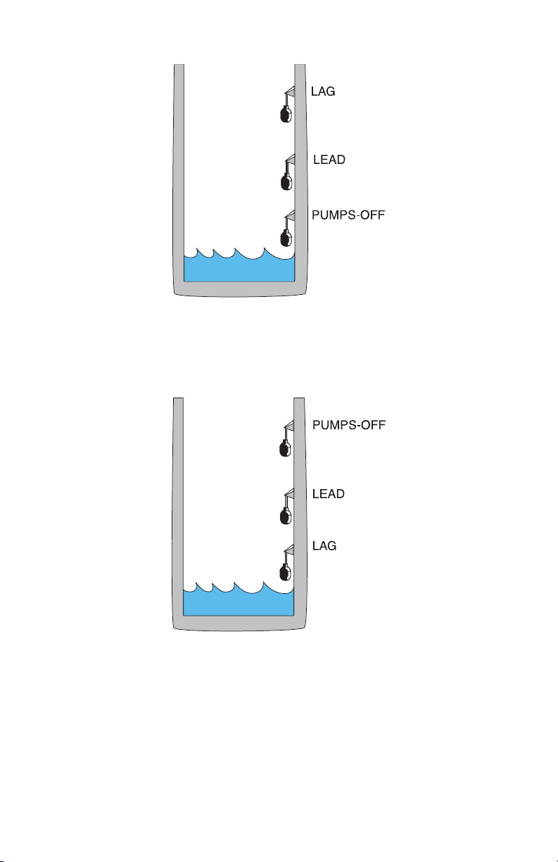
Skymetry WTU-14 Manual
Figure 1: Float positions for a drain application
In a Fill application, the Lag and Pumps-Off floats would change
position as shown below:
Fig 2. Float positions for a Fill application
In this case, the pumps are attempting to keep the well full. When
the well is full all three floats are closed. If the level drops below
the Lead float, then the first pump will turn on. If the level rises
above the Pumps-Off float then the pump will turn off. If the level
continues to fall below the Lag float, then the 2nd pump will turn
on. Both pumps will remain on until the Pumps-Off float closes.
54
Page 55

Chapter 6: Pump Control
If only one relay output is set to pump-control mode, then simplex
control is performed. In Simplex mode only the Lead float (Dry
Contact #6) and Pumps-Off float (Dry Contact #8) are required.
Either output relay can be used in simplex mode.
How it works—Analog Level Sensor
When performing pump control with an analog level sensor, the
Lead, Lag, and Pumps-Off levels are programmed into the Skymetry
software. The unit then measures the actual level on Analog Input
#6 and turns on the appropriate relay outputs. If both outputs are
set to Pump Control mode, then alternating duplex control will be
performed. If only one output is set, then Simplex control will be
performed. The analog level sensor must be a 4–20mA transducer
that is selected and calibrated based on the depth of the well. The
specified output of the transducer must be entered into the Table
Range settings for Analog Input #6.
Installation Recommendations
Be sure to install and wire the Skymetry WTU-14 and associated equipment in accordance with all local codes and regulations.
Adhere to Standard Practice/Best Practice policies when installing
and wiring any control system. Be sure to include hand-operated
switches to disconnect power on all pumps/equipment to insure
worker safety when installing and servicing equipment.
Programming for Pump Control
To program the unit for Pump Control, click on the Outputs tab.
55
Page 56
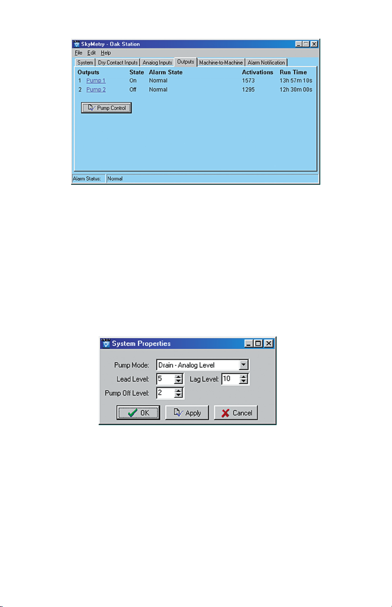
Skymetry WTU-14 Manual
Figure 2: Output properties showing pump control
Next, click on the Pump Control link. This will bring up the pump
mode setup screen. Next, select the type of pump control you want
to do:
= Drain Analog Level
= Drain Dry Contact Floats
= Fill Analog Level
= Fill Dry Contact Floats
Figure 3: Pump Mode—Analog programming
If you select one of the Analog modes, you will have to fill in the
Lead, Lag, and Pumps-Off fields. In Dry Contact Float mode these
fields are disabled. Enter the appropriate values and click OK or
Apply.
Next, click on the
output to use for Pump Control. Click the dropdown box and scroll to the bottom to select Pump Control. Click
OK or Apply. This will activate the Pump Control logic. Make sure
all input devices and equipment are operational and ready for use.
56
Page 57
Chapter 6: Pump Control
For test purposes you may wish to use hand operated switches to
manually control the pumps and simply watch the system LEDs
to see if the Skymetry WTU-14 is functioning properly. If you are
using “duplex” pump control, select the other output and set it for
Pump Control mode also. After verifying that the unit is function
ing properly, move your hand-operated pump switches to “Auto”
and verify that the WTU-14 is properly controlling the system.
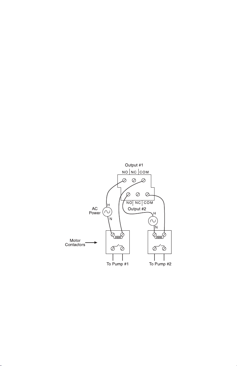
Output Wiring
The output relays on the Skymetry WTU-14 are for low current
control signals (0.3A 120VAC/1.0A 24VDC maximum).
DO NOT directly connect the power for the pumps to these relays—
THIS WILL PERMANENTLY DAMAGE THE WTU-14.
Use the WTU-14 outputs to control intermediate motor contactors/
relays that will switch actual power to the pumps.
-
Figure 4: Output wiring to two pumps
57
Page 58

Skymetry WTU-14 Manual
58
Page 59
Chapter 7: Machine-to-Machine Control
Chapter 7: Machine-to-Machine Control
The Machine-to-Machine Control feature allows you to control outputs of other Skymetry WTU-14 units (or outputs within the same
unit) based on input conditions. For example, you can switch an out
put on a WTU-14 unit several miles away if an input on a different
unit is greater than a specified value. The output being controlled
must be set to manual mode. Up to 8 machine-to-machine control
events can be configured per WTU-14 unit. Note that when an input
condition causes an output to change state, a separate event must be
programmed to make the output change back. For example, if you
program output #1 to turn on when input #5 is greater than 60, the
output will
event must be programmed to make the output turn off when the
input is less than 60.
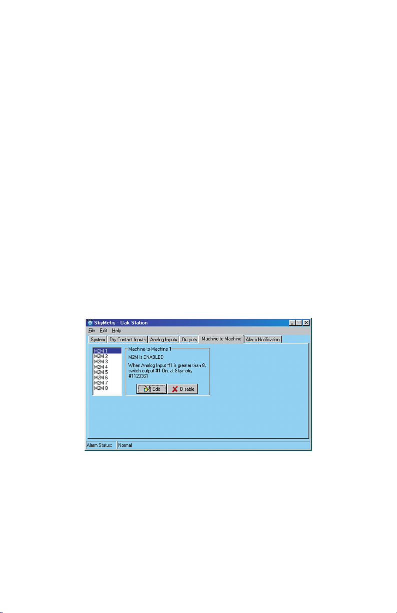
To program Machine-to-Machine Control click on the Machine-toMachine Tab. The following screen will appear:
not turn off when the input drops below 60. A separate
-
Figure 1: Machine-to-Machine tab
The 8 peer-to-peer events are listed in the window to the left.
Clicking on each one will display a description of the control event
programmed for each. To program a new peer-to-peer event click
on the first unused (Disabled) peer event and click the Edit button.
The following screen will appear:
59
Page 60

Skymetry WTU-14 Manual
Figure 2: Peer-to-peer Edit screen
Click the down arrow in the Input Trigger field to select the input
that will initiate the event. If you select a Dry Contact input, you
can have the event occur when the selected input goes from Open-
to-Closed or Closed-to-Open. If you select an Analog input you can
have the event occur if the input is equal-to
, greater-than, or less-
than a specified value.
Enter a value for the comparison (range: -16,384 to 16,383).
Note: peer-to-peer events are triggered as soon as
the input meets the trigger conditions. There is no
recognition time applied in this case. Also, peer-topeer events will not be executed while you are on
line locally.
Next, enter the SkyID and Password of the WTU-14 unit whose out
put you want to switch. Select the output number and action (either
ON or OFF). Click Apply or
OK when finished. Remember, the target output must be set to manual mode, otherwise the command will
be ignored. If the password is wrong the command will be ignored
as well.
Local Output Control
You can perform control logic using the same inputs and outputs on
a single WTU-14 unit. If you want to switch an output on the same
Skymetry WTU-14 as the input, then simply enter the unit’s own
SkyID (a password is not required in this case). The output must be
set to manual mode. Local output control does not use any airtime
and also executes instantly (as long as there are no preceding peer-topeer events that must communicate with a different WTU-14 device).
60
-
Page 61

Chapter 7: Machine-to-Machine Control
Important Information and Warnings
=It may take several minutes for the peer-to-peer command to
reach the destination Skymetry WTU-14.
=Peer-to-peer commands are processed in a sequential, non-pre-
determined order. This means that if more than one command
is triggered, the subsequent commands must wait until the cur
rently processed command is finished. If two peer-to-peer com
mands are triggered simultaneously that affect the same output,
the order of the processing cannot be guaranteed.
=Both the source and destination WTU-14 devices must be pow-
ered on and operational for peer-to-peer commands to operate
correctly.
=If the unit is in the middle of alarm processing, peer-to-peer
commands may be delayed while alarms are being sent.
=Peer-to-peer commands are not processed while logged in with
the PC software. The user should log off and the serial cable
should be unplugged during normal operation to ensure that
peer-to-peer commands are properly processed.
-
-
=Setting peer-to-peer trigger values too close can cause output
oscillations. Peer-to-peer commands are an advanced feature
and should be well thought out. Do not use them for critical
applications where the risk is unacceptable.
=All peer-to-peer control actions will use a wireless message
packet.
Sample Application
Suppose you had a well and a pump which were several miles apart.
When the pump runs, it fills the well. Your goal is to maintain a
certain level in the well. If you place one WTU-14 unit at each loca
tion you can have two peer-to-peer events accomplish your goal. In
addition, you can use the WTU-14 inputs to monitor other key items
such as:
• well level too low
• well level too high
-
61
Page 62
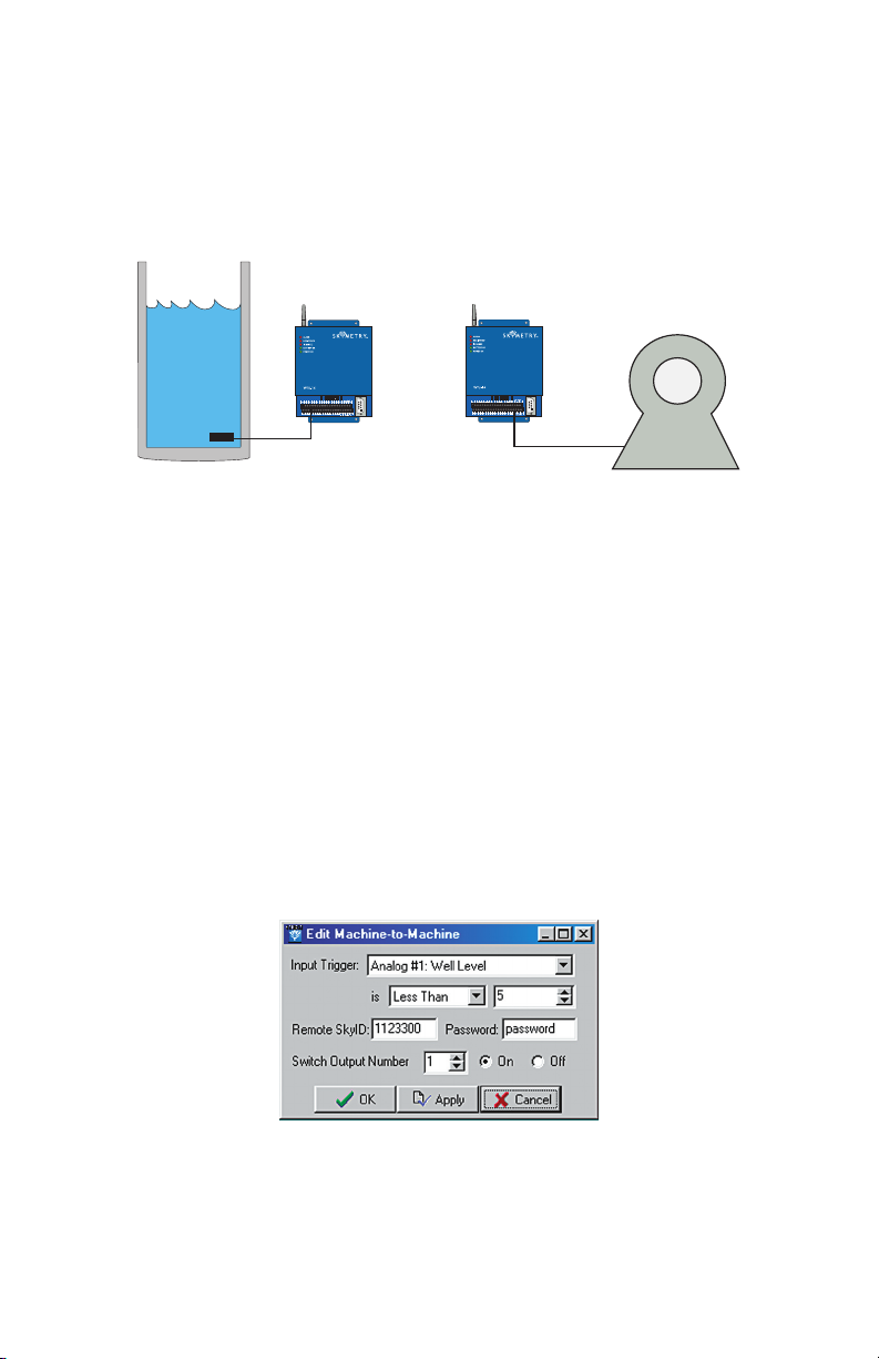
Skymetry WTU-14 Manual
• pump failure
• power failure
• generator on
• temperature
Figure 3: Well and Pump Control via Machine-to-Machine Commands
Let's suppose the well level is 25' and you need to maintain the
level between 5' and 20'. The first thing you would need is a level
transducer in the well. Next, program your two machine-to-machine
events into the WTU-14 located at the well. The first would be to
turn ON the pump if the level is Less-Than 5'. The second event
would be to turn the pump OFF if the level is Greater-Than 20'.
Consider the rate at which the well fills when the pump is running,
in order to account for the machine-to-machine command delay
time between the WTU-14 units. Also note that machine-to-machine
control is completely independent of alarm processing, so you can
also trip high or low-level alarms based on the well level.
Figure 4: Turn Pump On if Level is Less than 5 feet
62
Page 63

Chapter 7: Machine-to-Machine Control
Figure 5: Turn Pump Off is Level is Greater than 20 feet
63
Page 64

Skymetry WTU-14 Manual
64
Page 65

Chapter 8: Notification
Chapter 8: Alarm Notification
The Skymetry WTU-14 can deliver alarm message notif ications
by voice phone call, internet e-mail, and text messaging to various
messaging devices and cell phones. A total of 24 notification desti
nations can be programmed to be contacted in the event of an alarm.
The unit also lets you to set an escalation level for each destination,
allowing you to have a group of people contacted f irst (tier 1) and,
if the alarm is not acknowledged, a second group of people (tier 2)
contacted. You can program up to 24 tier levels of destinations and
include a programmable delay time between each tier.
How does notification work
Once an alarm occurs, the Skymetry will begin sending its alarm
message to the programmed destinations. The unit will start with
destinations at tier 1. Once the Tier Delay expires, the unit will start
sending alarm messages to destinations in the next tier. The Tier
Delay time begins as soon as the alarm occurs, so if it were programmed to 60 minutes, the next tier would start receiving alarm
messages one hour after the alarm occurred. The Skymetry will
send its alarm message to each destination until it receives acknowl
edgment, or it will automatically acknowledge the alarm after all
destinations have been sent the message or when the last tier delay
time has expired.
-
-
Note: If you are logged in through the serial port, no alarms
will be sent until you log off and disconnect the serial cable. If
you acknowledge the alarm through the software before logging
off, no alarm messages will be sent. This can be useful for per
forming on-site maintenance or testing the system. If you are
not logged on through the serial port the alarm messages will be
sent immediately, one at a time.
-
65
Page 66
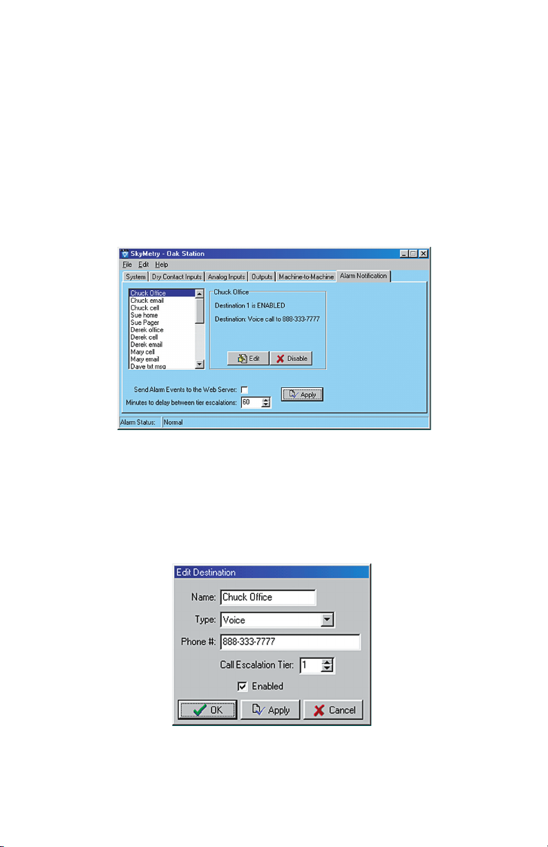
Skymetry WTU-14 Manual
Voice Phone Call
The WTU-14 can send alarm messages via a voice telephone call.
It does this without having a telephone line connected to the unit.
When an alarm message is sent as a voice call the number is dialed
from the Skymetry Messaging Service Center. The message is spo
ken from a computer that will customize the message based on the
programming in your Skymetry WTU-14 including the programmed
Unit Name
a Voice destination, click on the Alarm Notification tab.
, Destination Name, SkyID, and Input Name. To program
-
Figure 1: Alarm Notification
This screen provides a list of the programmed alarm destinations.
To program or change a destination’s information, click on the name
of the person to edit (or select unused for a new entry) and then
click the
66
Edit button. The Edit Destination screen will appear:
Figure 2: Contact Edit for Voice Call
Page 67

Chapter 8: Notification
Enter the name for this destination (up to 12 characters) and in the
Type field select Voice. In the Phone # field enter the area code and
telephone number. A sample alarm telephone call is shown below:
“Hello, Sensaphone Inc. has a message for ‘Mike’
<destination name>.”
“To accept the message press 1.”
“To cancel the message press 2.”
{press 1 to hear the alarm message}
“Skymetry alarm at 'Oak Station' <unit name>
,
SkyID number ‘1123350’ <skyid>.”
“Contact 4, ‘High Float’ <input name> is in alarm.”
To acknowledge send #### <alarm ID>
“To replay message, press the * key.”
“To reply to the message, press 2.”
“To end this call, press 3.”
To acknowledge the alarm you must press “2” (reply to the mes
sage). Next, enter the four digit alarm ID that was spoken at the end
of the message followed by the “#” key. When prompted to send the
message, enter the “#” key again. The alarm ID is a unique number
that identifies the alarm and the destination. Note that a different
alarm ID number will be sent to each destination—even for the
same alarm.
Internet E-Mail
The WTU-14 can send alarm messages to internet e-mail addresses. The alarm message will comprise information from within
your Skymetry WTU-14 including the programmed Unit Name
Destination Name, and Input Name. To program an e-mail destina
tion, click on the Alarm Notification tab.
-
,
-
67
Page 68
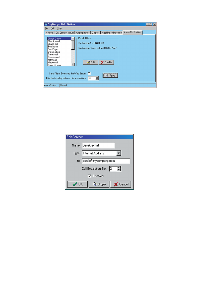
Skymetry WTU-14 Manual
Figure 3: Alarm Notification
This screen provides a list of the programmed alarm destinations.
To program or change a destination’s information, click on the name
of the person to edit (or select unused for a new entry) and then
click the
Edit button. The Edit Destination screen will appear:
Figure 4: Destination Edit for E-mail
Enter the name for this destination (up to 12 characters) and in the
Type field select Internet E-mail. In the To: field enter the e-mail
address (up to 34 characters).
Warning: Before entering an e-mail address into
the Skymetry WTU-14, be sure to test the address
first, using your computer and standard email soft
ware. Verify that the address is working and that the
message is delivered.
A sample e-mail alarm message is shown below:
From: [email protected]
68
-
Page 69
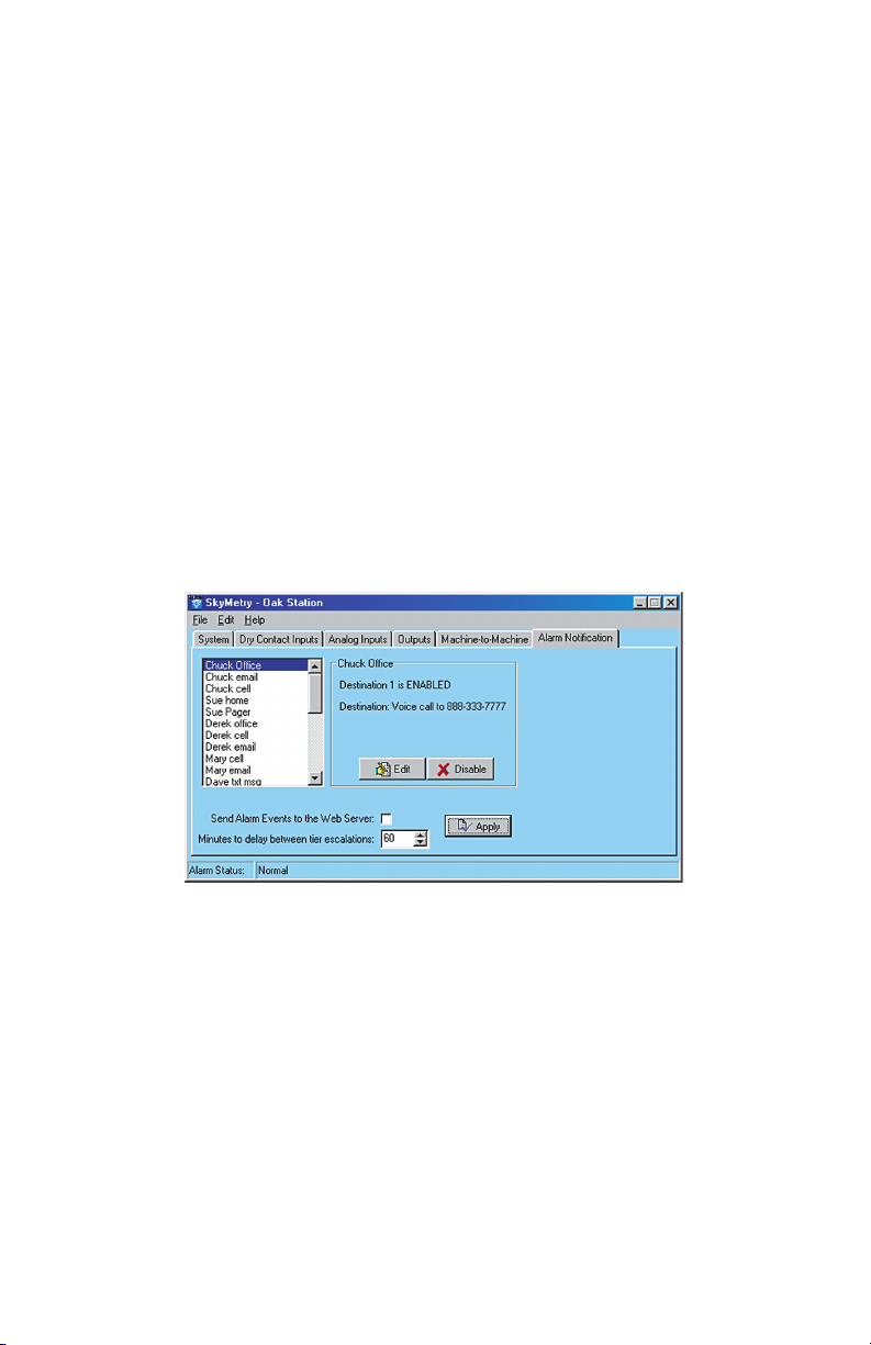
Chapter 8: Notification
High 4-20mA ALARM at Oak Station Sky ID#1123350
Analog 1 Well level is now 26
Level crossed limit of 15
To acknowledge, send 1302
Alphanumeric Pager
The WTU-14 can send alarm messages to your alphanumeric pager
or mobile text messaging device. The message will be sent to an
e-mail address for your pager based on your paging provider and
your pin number. The provider-format list below will instruct you
on how to enter the e-mail address for your particular service pro
vider. The alarm message will comprise information from within
your Skymetry WTU-14 including the programmed Unit Name
Destination Name, and Input Name. To program an e-mail destina
tion click on the Alarm Notification tab.
-
,
-
Figure 5: Alarm Notification
This screen provides a list of the programmed alarm destinations.
To program or change a destination’s information, click on the name
of the person to edit (or select unused for a new entry) and then
click the
Edit button. The Destination Edit screen will appear:
69
Page 70
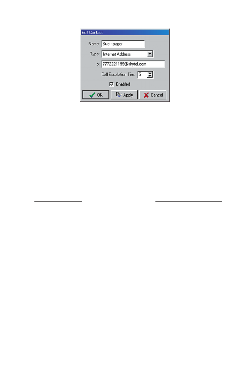
Skymetry WTU-14 Manual
Figure 6: Destination Edit for Alphapager
Enter the name for this destination (up to 12 characters) and in the
Type field select Internet E-mail. In the To: field enter the e-mail
address as described in the list below (up to 34 characters).
Warning: Before entering an e-mail address into
the Skymetry WTU-14, be sure to test the address
first, using your computer and standard email soft
ware. Verify that the address is working and that the
message is delivered.
-
Paging Provider
Advantage Communications [email protected]
Airtouch Pagers [email protected]
AT&T Paging [email protected]
Bell South (Blackberry) [email protected]
Carolina Mobile Communication [email protected]
Central Vermont Comm. [email protected]
Communication Specialists [email protected]
Communication Specialist Co. [email protected]
Cook Paging [email protected]
Digi-Page / Page Kansas [email protected]
GrayLink / Porta-Phone [email protected]
GTE Paging [email protected]
Indiana Paging Co. [email protected]
70
E-mail Address Format
Page 71

Chapter 8: Notification
Infopage Systems [email protected]
JSM Tele-Page [email protected]
Metrocall [email protected]
Metrocall 2-Way [email protected]
MobileComm [email protected]
Morris Wireless [email protected]
Motient [email protected]
Pagemart Advanced and 2-Way [email protected]
PageNet Canada rim devices [email protected]
ProPage [email protected]
RAM Page [email protected]
Satellink [email protected]
SkyTel [email protected]
ST Paging [email protected]
Teletouch [email protected]
TSR Wireless [email protected]
Verizon Wireless [email protected]
WebLink Wireless [email protected]
Text Messaging to Cell Phones
The WTU-14 can send alarm messages to your wireless cellular
telephone. The message will be sent to an e-mail address for your
cell phone based on your cellular provider and your telephone
number. The cell-provider/format list below will instruct you on
how to enter the e-mail address for your particular service provider.
The alarm message will be composed of information from within
your Skymetry WTU-14 including the programmed Unit Name
Destination Name, and Input Name. To program an e-mail destina
tion, click on the Alarm Notification tab.
,
-
71
Page 72
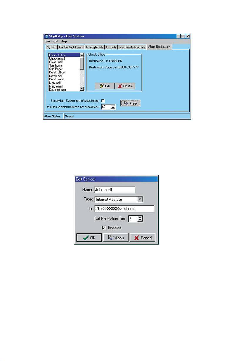
Skymetry WTU-14 Manual
Figure 7: Alarm Notification
This screen provides a list of the programmed alarm destinations.
To program or change a destination’s information, click on the name
of the person to edit (or select
click the
Edit button. The Edit Destination screen will appear:
unused for a new entry) and then
Figure 8: Destination Edit for Cell Phone
Enter the name for this destination (up to 12 characters) and in the
Type field select Internet E-mail. In the To: field enter the e-mail
address as described in the list below (up to 34 characters).
Warning: Before entering an e-mail address into
the Skymetry WTU-14, be sure to test the address
first, using your computer and standard email soft
ware. Verify that the address is working and that the
message is delivered.
72
-
Page 73

Chapter 8: Notification
Cellular Provider E-mail Address Format
3 River Wireless [email protected]
Airadigm (Einstein PCS [email protected]
AirTouch Cellular [email protected]
AT&T Pocketnet PCS [email protected]
ATT Wireless [email protected]
Bell South [email protected]
Bell South [email protected]
Blackfoot Communications [email protected]
Carolina West Wireless [email protected]
CellularONE [email protected]
Cellular One East Coast [email protected]
Cellular One PCS [email protected]
Cellular One [email protected]
Cellular One [email protected]
CellularSouth [email protected]
Cingular [email protected]
Clearnet [email protected]
Green's Communications [email protected]
MCI Phone [email protected]
Nextel [email protected]
Nextel [email protected]
Ntelos [email protected]
PacificBell/Nevada Bell [email protected]
PrimeCo [email protected]
Qwest [email protected]
Rogers Canada [email protected]
SMF/Schuylkill Mobile Fone [email protected]
SouthernLinc [email protected]
Sprint [email protected]
Suncom [email protected]
SunCom [email protected]
T-Mobile [email protected]
73
Page 74

Skymetry WTU-14 Manual
T-Mobile [email protected]
Telecorp [email protected]
Tritel [email protected]
Triton PCS [email protected]
U.S. West [email protected]
Verizon [email protected]
VoiceStream [email protected]
Wyndtell
Acknowledgment via E-mail or Text Message
The alarm from the Skymetry WTU-14 can be acknowledged by
replying to the alarm message that was sent to you. As long as you
received the message on a two-way data device, you can simply
reply back to send your acknowledgment. In the reply message,
just enter the alarm ID number in the message. For example, if the
alarm ID number was 1720, then you would reply with a “1720” in
your reply message to indicate to the WTU-14 that you received and
acknowledged the alarm message. A sample acknowledgment mes
sage is shown below:
-
To: [email protected]
From: [email protected]
1720
Additional Information
If another alarm occurs while the unit is delivering messages for a
previous alarm, the second alarm will be handled after the first is
acknowledged.
You can use tier escalation to organize the destination delivery. Set
each destination to its own tier level and set the delay to two min
utes. In this case a new message will be sent every two minutes to
the next tier level.
Rearranging the destination order can be done simply by changing
the Tier Levels.
74
-
Page 75

Chapter 9: Operation
Chapter 9: Operation
After installation and programming have been completed, the
Skymetry WTU-14 is fully operational. This chapter explains how
the WTU-14 operates.
PART ONE: Alarm Notification and Acknowledgment
There are 3 stages to a complete alarm event: 1) Alarm Recognition,
2) Alarm Notification, and 3) Acknowledgment.
Note that not all fault conditions will go through each stage. For
example, some may not meet the recognition time.
Alarm Recognition
1) The WTU-14 monitors 8 dry contact inputs, 6 analog inputs,
main power, and battery backup. When the status of an input
changes or exceeds user-programmed limits, it causes a fault
condition.
2) If the fault condition lasts long enough to meet its programmed
recognition time, the fault condition becomes an alarm and the
WTU-14 begins the alarm notification sequence.
Alarm Notification
The WTU-14 can send alarms via Voice phone call, E-mail,
Alphanumeric pager, or Text message to wireless (cell) phone.
Dialout Note: Call Progress
The Skymetry WTU-14 monitors call progress when dialing out
in voice mode. If it dials out and encounters a busy signal or no
answer it will wait about a minute and try again up to 3 times. If the
call is answered by an answering machine or voice mail system the
alarm message will likely not be recorded because it will be speak
ing while your greeting message is playing. Note that since the call
was actually answered, the WTU-14 will consider the call completed
and not dial it again.
-
75
Page 76

Skymetry WTU-14 Manual
Alarm Notification—Voice
When dialing out to a destination programmed as “voice,” the
Skymetry WTU-14 waits for the phone to be answered, then recites
its identification message, then the message identifying the input
that has gone into alarm.
Below is an example of what the WTU-14 would say during a typi
cal ‘voice’ notification:
“Hello, Sensaphone Inc. has a message for ‘Dave’ <destination name>.”
“To accept the message press 1.”
“To cancel the message press 2.”
{press 1 to hear the alarm message}
“Skymetry alarm at 'Oak Station' <unit name>, SkyID number ‘1123350’
<skyid>.”
“Contact 1, ‘Security’ <input name> is in alarm.”
“To acknowledge, send 1201
“End of message”
“To replay message, press the * key.”
“To reply to the message, press 2.”
“To end this call, press 3.”
<alarm ID>”
Alarm Notification—E-mail
When sending an alarm message via e-mail the WTU-14 will compose a text message based on the Unit's name, SkyID, Input name,
Input type, current value, and alarm limit (where applicable). A
sample alarm message is shown below:
-
To: [email protected]
From: [email protected]
Contact ALARM at Oak Station Sky ID#1123350
Contact 1 Security is in alarm
To acknowledge send 1202
76
Page 77

Chapter 9: Operation
Alarm Notification—Alphanumeric Pager
When sending an alarm message to an Alphanumeric pager, the
WTU-14 leaves a text message on the display of the pager. A sam
ple is shown below:
High 4–20mA ALARM at Oak Station Sky ID#1123361
Analog 1 Water level is now 21
Level crossed limit of 15
To acknowledge send 1203
Alarm Notification—Text Message to Cell Phone
When sending an alarm text message to a cell phone the WTU-14
leaves a message on the display of the phone. A sample is shown
below:
High 4-20mA ALARM at Oak Station Sky ID#1123361
Analog 1 Water level is now 21
Level crossed limit of 15
To acknowledge send 1204
-
Tier Delay
You can group destinations into tiers and then program a delay
time until the next tier gets called. This allows you to contact your
primary personnel first and, if necessary, escalate the calling to the
next level. Up to 24 tiers can be configured. The WTU-14 will start
sending alarm messages to all destinations programmed in Tier 1.
If the alarm is acknowledged, it will halt the notification process for
that alarm and no additional alarm messages will be delivered. If all
of the Tier 1 destinations have been sent the alarm message and no
acknowledgement was received, the unit will wait the programmed
Tier Delay Time and then start sending the alarm to the destinations
in the next Tier. An example is described below:
77
Page 78

Skymetry WTU-14 Manual
Tier 1 destinations: Tier 2 destinations: Tier 3 destinations:
Chuck Janet Morton
Mary George Zach
Sue Ron Tony
Derek Jason
Dave Carmen
Tier Delay Time: 60 minutes
An alarm occurs at 8:00
PM
The Skymetry WTU-14 starts sending alarm messages to members
of Tier 1.
No one acknowledges the alarm.
At 9:00
PM the Tier delay has expired and the unit begins to send
alarm messages to members of Tier 2.
At 9:30
PM the WTU-14 receives an acknowledgement message and
the unit stops the notification process.
The people in Tier 3 do not get contacted.
Alarm Acknowledgment
Acknowledging an alarm will halt the alarm notification process.
Voice notification alarms must be acknowledged during the original
phone call. E-mail, Alphanumeric pager, and Cell phone alarms can
be acknowledged by replying back to the original alarm message or
by sending the unit a message with the alarm ID number. The sec
tions below detail the procedure to acknowledge an alarm.
Alarm Acknowledgment—Voice Notification
“Hello, Sensaphone Inc. has a message for 'Dave' <destination name>.”
“To accept the message press 1.”
“To cancel the message press 2.”
{press 1 to hear the alarm message}
“Skymetry alarm at 'Oak Station' <unit name>, SkyID number '1123350'
<skyid>.”
“Contact 1, 'Security' <input name> is in alarm.”
“To acknowledge send 1101
“End of message”
<alarm ID>”
-
78
Page 79

Chapter 9: Operation
“To replay message, press the * key.”
“To reply to the message, press 2.”
“To end this call, press 3.”
To acknowledge the alarm you must press “2” (reply to the message). Next, enter the four digit alarm ID that was spoken at the
end of the message followed by the “#” key. When prompted to send
the message, enter the “#” key again. The WTU-14 will respond by
saying: “Alarm sent.” The alarm has been acknowledged and the
notification process stops. If the Touch-Tone acknowledgment code
is not received, the Skymetry WTU-14 will continue to send alarm
messages to the remaining destinations.
Note: An alarm cannot be acknowledged using a
pulse (rotary) telephone.
Alarm Acknowledgment—Alphanumeric Pager
When sending an alarm message to an Alphanumeric pager, the
WTU-14 leaves a text message on the display of the pager. If you
have a two-way alphanumeric pager you can acknowledge the alarm
by replying to the original message with the alarm ID number,
which will acknowledge the alarm. For example, if the alarm ID
was 1503, you would simply reply back with “1503.” If you do not
have a two-way pager then you can send the WTU-14 an e-mail
using either a computer or a cell phone. The e-mail address of your
Skymetry WTU-14 is [email protected], where you would
substitute the word skyID with your SkyID number. In the message
area simply send the unit the alarm ID number.
Alarm Acknowledgment—Text Message to Cell Phone
When sending an alarm message to a cell phone, the WTU-14
leaves a text message on the display of the phone. You can acknowl
edge the alarm by sending a reply back to the WTU-14 with the
alarm ID number, which will acknowledge the alarm. For example,
if your alarm ID number was 1107, you would simply reply back
with “1107.” Alternatively you can send the WTU-14 an e-mail
using a computer. The e-mail address of your Skymetry WTU-14
is [email protected], where you would substitute the word
skyID with your SkyID number. In the message area simply send
the the alarm ID number.
-
79
Page 80

Skymetry WTU-14 Manual
Alarm Acknowledgment—Automatic
The Skymetry WTU-14 will acknowledge an alarm itself (automatically) if all of the destinations have been contacted and no acknowl
edgement was received.
-
80
Page 81

Chapter 9: Operation
PART TWO: Status Request
You can request a status report from your WTU-14 by sending it a
command via e-mail. When the unit receives the command it will
assemble a status report and send it back to the originating e-mail
address. Only inputs that are enabled will be included in the report.
If alarm monitoring is not enabled for a particular input, its status
will be displayed as disabled. To request the status report you need
the unit’s password and skyID. The e-mail format to request a status
report is shown below:
To: skyID@mobilemessage.com {replace skyID with your unit’s skyID number}
Subject:
Message:
p password gst {replace password with your unit’s password}
A sample e-mail Status Report is shown below:
D1: Pump 1 Run 243:33:12 1591 OK
D2: Pump 2 Run 012:30:00 1295 OK
D3: High Water 000:00:00 0 OK
D4: Door sensor 000:00:00 0 Alarm
D5: Pump 1 fault 000:00:00 0 OK
D6: Pump 2 fault 000:00:00 0 OK
D7: Gen. Run 000:57:49 2 Disabled
D8: Low Fuel 000:00:00 0 OK
A1: Well Level 16 OK
A2: Outside Temp 78 F Disabled
A3: Cabinet Temp 86 F OK
A4: Fuel Level 38 OK
A5: Battery Temp 81 F OK
A6: Flow Rate 33 OK
B: Battery 13.50v OK
P: Power 16.82v OK
O1: Pump 1 On 015:54:44 1573 OK
O2: Pump 2 Off 012:30:00 1295 OK
81
Page 82

Skymetry WTU-14 Manual
82
Page 83

Chapter 10: Web Page
Chapter 10: Skymetry Web Page
The Skymetry Web Page is where you can check status, monitor
data message usage, make programming changes, and even control
outputs from any internet connected computer. In order for your
unit to be accessible via the web page you must first change the
password in your unit and then log out. This will instruct the unit
to register with the Skymetry web server, setup an account for your
unit, and perform a Full Programming Update. Note that it may
take 1 to 2 hours for the web server to receive all of the program
ming information from your Skymetry WTU-14. Do not make any
programming changes to your unit during this period. This initial
Full Update will occur automatically and is included in your activa
tion fee and does not count toward your monthly allowance.
Once the Skymetry web server has finished receiving the updates
from your unit you can go to www.skymetry.com, enter your SkyID
and Password, and click Login. The web page for your Skymetry
WTU-14 will be displayed. The web page presents a view of the
system which is very similar to the Skymetry PC Software, except
for the fact that it is a snapshot of information from a specific point
in time—it is not updating in real-time. To retrieve the latest values
you must click either the Status Refresh or Programming Refresh
links.
-
-
Note: It is highly recommended that if at any
time you make any programming changes locally
(at the unit via the serial port) that you click the
Programming Refresh link on the web page soon
thereafter, to ensure that the information you are
viewing is up to date. This will also ensure that the
alarm history information will also be accurate.
Status Refresh
You can retrieve the latest input and output values by clicking
the Status Refresh link. This will send a message to the WTU-14
requesting the latest input and output status information. When
83
Page 84

Skymetry WTU-14 Manual
the unit receives the request it will immediately send back a reply.
During this waiting period the web page will display the input and
output values in green italics until the updated information returns.
At the bottom of the screen is a time-stamp which indicates the date
and time of the last update. Note that clicking the Status Refresh
will use 5 to 7 data messages, depending on the amount of data
transferred. You can minimize the number of data messages by dis
abling any inputs which are not being used.
Programming Refresh
The Programming Refresh command will refresh all Skymetry
WTU-14 programming as well as input/output status. The first
Programming Refresh is included as part of the activation fee and
will not increment the data message counter nor be applied to your
monthly allowance. You only need to click this button if you believe
that programming changes may have occurred locally, at the unit,
and you want to refresh the information on the web server.
Programming via the Web Page
-
You can change any parameter in your WTU-14 from the web page,
just as you would using the Skymetry PC Software. All program
mable items will appear as Blue links. For the inputs you can click
on any item for that channel and the respective programming screen
will appear. If you change an item and click OK, the change will be
sent to your unit. This will take a few minutes to process. Similarly
you can change Output programming, Notification programming,
and Machine-to-machine programming.
Switching Outputs via the Web page
To switch an output, Login to the web page and click Outputs.
Next, click on the Output number you want to switch. On the pro
gramming screen, locate the State field and select On or Off, then
click OK. The command to switch the output will be sent to your
unit. Note that this may take 1–2 minutes.
84
-
-
Page 85

Chapter 10: Web Page
Account Usage
The main status screen displays an Account History containing the
number of data messages used for the month as well as historical
usage. Data messages are those used during a wireless data transfer
to or from the unit. They are sent whenever an alarm is delivered,
a machine-to-machine command is sent, programming changes
are made, or if the Status Refresh/Programming Refresh links are
clicked. The number of data messages used per transaction varies
depending on the type of transaction and the programming param
eters within the unit. Some typical values are listed below:
Transaction Description Data Messages
Status Refresh 5–7
Programming Refresh 9–115
Machine-to-machine command 1
Voice Alarm 2–4
E-mail alarm 1–3
-
Alarm message to web server 1
Programming change (1 item) 2
E-mailed Status via GST command 2–7
Alarm History
An alarm history log is available on the web page to provide details
on alarms that have occurred and whom acknowledged them. The
log can be queried by entering a start and end date range, or by
selecting one of the QuickDates options. You must have the Send
alarm events to the server option enabled in order for the alarm
events to appear on the web page. This option is configured on the
Notification programming screen. Note that the time stamps appear
ing on the web page do not indicate when the alarm occurred, but
rather the time that they were received by the web server.
-
85
Page 86

Skymetry WTU-14 Manual
86
Page 87

Chapter 11: Testing
Chapter 11: Testing the Skymetry WTU-14
It is extremely important that you test the system after installation
to make sure that it is working properly and that all programming is
correct. In addition, it is highly recommended that you test and/or
verify proper operation on a weekly basis to ensure that the system
continues to function as required. (See Appendix A.) The following
items should be tested:
• Notification to all destinations to make sure that each one is pro
grammed correctly and that the messages are actually delivered.
• Input testing to make sure that the system is reading them cor
rectly and that when a fault occurs the system responds appro
priately.
• Output testing to make sure they are wired correctly and that
they switch on and off when instructed.
• Control programming—Local control, Machine-to-machine,
or Pump control—to make sure that the system is functioning
properly, as required for your application.
Notification Testing
Create an alarm and confirm that all destinations receive the alarm
message. This can be done by forcing an input into alarm, by
temporarily adjusting an alarm limit, or by changing the normality
of a Dry Contact input. The Alarm LED on the front of the unit will
begin blinking when an alarm has occurred. Be sure to disconnect
from the serial port after creating the alarm, otherwise the
notifications will not be sent. After confirming that all notification
messages were delivered, correct the alarm condition and/or adjust
your programming as required.
-
-
-
Input Testing
Check the current value of all of the programmed Dry Contact
and Analog Inputs. Make sure that the values being displayed are
correct.
87
Page 88

Skymetry WTU-14 Manual
For Dry Contact inputs, momentarily reverse the input condition
to verify that the unit recognizes the change of state. For example,
if you have a normally open sensor connected to Dry Contact #1,
force that sensor closed and verify that the unit displays the value as
closed.
For analog inputs, verify that the input reading matches the entity
being measured. For example, for temperature inputs confirm that
the unit is reporting the correct temperature.
For 4–20mA inputs, confirm that the level or value being displayed
in the WTU-14 matches the actual conditions being measured.
Output Testing
Confirm that the power limitations of the outputs will not be
exceeded. The WTU-14 outputs are rated for a maximum of 0.3A
at 120VAC or 1.0A at 24VDC. Test the outputs by switching them
on and off manually and confirming that the device being controlled
turns on and off. The Output LEDs on the front of the unit should
also turn on and off.
Control Programming
For applications that utilize control programming it is important
to test all scenarios that may affect system operation. This means
you should test your system under normal operating conditions as
well as abnormal (or failure) conditions to make sure that you have
designed your system to operate under the worst-case scenario.
Note that Local and Machine-to-Machine control will not execute
while you are connected locally.
To test Local control operation, force input conditions as necessary
to activate the output(s). Confirm that the input-to-output control
logic is executing properly. Test each programmed control algorithm
separately to make sure that each one is functioning as desired.
To test Machine-to-Machine control, force input conditions as nec
essary to activate the output(s) on your remote WTU-14 device(s).
Confirm that the outputs on the remote unit(s) have turned on or off
as instructed. Test each programmed control algorithm separately
88
-
Page 89

Chapter 11: Testing
to make sure they are all functioning. Have the system go through
a complete automated control cycle of your system to confirm that
the unit and its programming are operating as intended.
Pump Control
To test Pump Control using float switches, force the float switch
inputs open or closed as necessary, to make the output(s) turn on
or off. In a Drain application the first pump would turn on if the
Pumps-Off and Lead float switches were closed. The second pump
would turn on if the Lag float switch also closed. Both pumps
would then turn off when all three float switches opened. In a fill
application, the first pump would turn on when the Pumps-Off and
Lead floats opened. The second pump would turn on when the Lag
float also opens. Both Pumps would turn off when all three floats
closed.
To test Pump Control using a level transducer you can temporar
ily force the input level to a certain value by adjusting the calibra
-
tion for the Analog Input. In a drain application, force the input to
be above the Lead level and the first pump should turn on. If you
then set the input above the Lag level, the second pump should also
turn on. Setting the input below the Pumps-Off setting will turn
both pumps off. In a fill application, setting the input below the
lead level will turn the first pump on. Setting the input below the
Lag level will turn on the second pump. Setting the input above the
pumps-Off level will turn off both pumps.
Once you have confirmed that the WTU-14 is controlling the sys
tem properly, allow the system to operate automatically. Observe a
complete Drain or Fill cycle and verify that the system is operating
as required.
89
Page 90

Skymetry WTU-14 Manual
90
Page 91

Appendix A: Checking for Proper Operation
APPENDIX A: Checking Your Skymetry WTU-14 for Proper Operation
We recommend that you test your Skymetry WTU-14 weekly to be
sure it is functioning properly. This will ensure that when a problem
arises the Skymetry WTU-14 will be ready to alert the appropriate
personnel. A blank Test Log is included at the back of this manual.
There are several tests to be performed:
1. Request a Status Report from the unit by sending it an e-mail
message and verifying the reply. This will test the unit’s ability to
receive and send a message. It will also verify that all of the inputs
are reading properly, the alarm conditions are OK, the electricity is
on, and the battery is OK.
2. Create an alarm on each input by tripping all connected sensors.
This will verify that each input is being recognized by the unit and
that it is programmed properly.
Temperature sensors: Heat or cool the sensor.
Motion sensors: Have someone walk in front of the sensor.
Door and window sensors: Open the door or window.
Water sensors: Apply a small amount of water beneath the sensor
or use a wet towel and touch it to the sensor probes.
Humidity sensors: Raise the humidity around the sensor by hold
ing a cup of very hot water beneath it.
4–20mA Transducers: Verify that the WTU-14 is reading the prop
er level by measuring the monitored quantity using alternative
methods.
Allow the unit to send its alarm message to all programmed con
tacts. This will make sure that the WTU-14 is programmed properly.
It will also prepare personnel to respond appropriately when they
receive a call from the WTU-14.
-
-
91
-
Page 92

Skymetry WTU-14 Manual
3. Test the battery by unplugging the AC adapter and making sure
that the WTU-14 continues to function. Check the LEDs to make
sure that the Power LED starts to blink and the Battery LED glows
steadily. Keep the AC adapter unplugged so that a Power Failure
alarm occurs. Allow the unit to send its alarm message to all pro
grammed contacts while running on battery backup. Plug in the AC
adapter after the unit has finished sending all of its messages.
4. If you require assistance, contact Phonetics Technical Support at
(610) 558-2700.
-
92
Page 93

Appendix B: Troubleshooting
APPENDIX B: Troubleshooting
I can’t communicate with my unit locally.
• Make sure you have entered the proper SkyID.
• Make sure the cable is connected from your computer to the
WTU-14.
• Make sure you have the right Com port selected (typically 1 or
2).
• Make sure the unit is receiving power.
I can’t access my unit on the web page.
• Have you logged in locally to your WTU-14 and changed the
password? This is required to initialize the web page.
• Have you entered the proper SkyID and Password
?
Why is the ‘IN RANGE’ LED off?
• If the unit is not within range of the wireless network the LED
will not turn on.
• It typically takes 1-2 minutes from power-up for the WTU-14 to
recognize the wireless network and turn on the LED.
• Make sure the unit is receiving power.
Why is the ‘REGISTERED’ LED off?
• If the IN RANGE LED is lit but the REGISTERED LED is not,
then the unit is not activated yet.
• Make sure the unit is receiving power.
93
Page 94

Skymetry WTU-14 Manual
Why is the ‘BATTERY OK’ LED off?
• There is no battery connected.
• The battery voltage is low.
Why is the ‘POWER OK’ LED off?
• The main power has failed and the unit is running batteries.
• The voltage at the Vin terminals is low.
Why is the ‘ALARM’ LED blinking?
• There is an unacknowledged alarm.
Why is the ‘ALARM’ LED on?
• There is an alarm but it has been acknowledged.
Why won’t the unit send me alarm messages?
• The WTU-14 will not send any alarm messages if you are connected locally.
• There are no destinations programmed.
• None of the destinations are enabled.
• The unit is not activated on the wireless network
• The destinations are not programmed correctly.
• There are no unacknowledged alarms.
My unit won’t make a voice call.
• The telephone number is programmed incorrectly. It should only
include the area code and number (e.g., 10 digits). Do not enter
a 1 as the first digit.
• The WTU-14 will not send any alarm messages if you are con
nected locally.
94
-
Page 95

Appendix B: Troubleshooting
• There are no destinations programmed.
• None of the destinations are enabled.
• The unit is not activated on the wireless network
• There are no unacknowledged alarms.
My unit won’t send a text message to my cell phone or
alphanumeric pager.
• The Destination is programmed incorrectly. You must use the
e-mail address format for your cellular or paging provider as
specified in chapter 8.
• The Destination type is set incorrectly. It should be set to
Internet E-mail Address
.
• The WTU-14 will not send any alarm messages if you are con
nected locally.
• There are no destinations programmed.
• None of the destinations is enabled.
• The unit is not activated on the wireless network
• There are no unacknowledged alarms.
-
Why does the unit call people even after I acknowledged
the alarm?
• When an alarm occurs the unit will begin to sequentially broadcast all alarm messages for the first Tier. Depending on how
quickly they get dispatched from the messaging center its possi
ble for additional calls to be made even after the alarm has been
acknowledged. Once the message is received at the messaging
center it will be called regardless of acknowledgement.
My unit won’t execute a Local machine-to-machine
command.
-
• Machine-to-machine commands will not execute while you are
connected locally.
95
Page 96

Skymetry WTU-14 Manual
• The output you are trying to switch is not set to manual mode.
• The input condition for the machine-to-machine command is not
being met.
My unit won’t execute a Remote machine-to-machine command.
• Machine-to-machine commands will not execute while you are
connected locally.
• The output on the remote unit you are trying to switch is not set
to manual mode.
• The input condition for the machine-to-machine command is not
being met.
• The SkyID and Password for the remote unit is programmed
incorrectly.
My WTU-14 isn’t displaying the correct value from my
4–20mA transducer.
• The analog input jumper isn’t set to the 4–20mA position.
• The analog input “type” isn't set to 4–20mA in the software.
• The transducer is not wired correctly.
• The transducer is not calibrated for the desired measurement
range.
• The analog input table values aren’t programmed to the calibrat
ed range of the transducer.
• The transducer is not compatible with single-ended inputs there
fore an isolation device is required.
My temperature sensor isn’t displaying the correct value.
• The analog input jumper isn’t set to the Temperature position.
• The analog input “type” isn’t set to Temperature in the software
• The temperature sensor isn’t a compatible 10K thermistor.
96
• The temperature sensor isn't wired correctly.
-
-
Page 97

Appendix B: Troubleshooting
Why don’t the values displayed on the web page match
the values displayed in the Skymetry software?
• The web page displays a snapshot of the values at a particular
moment in time. It does not display real-time values, as is the
case when connected locally through the Skymetry software.
• Click the Status Update button on the web page to retrieve a
current snapshot.
Why can’t I get pump control to work?
• The Output(s) are not set to Pump Control mode.
• The Pump Control parameters are programmed incorrectly.
• The level transducer is not wired to analog input #6.
• The level transducer is not reading the proper values.
• The float switches are not wired to Dry Contact inputs #6, #7,
and #8.
• The float switches are not Normally Open
• The Lead
, Lag, and Pumps-Off float switches are not wired to
the proper inputs.
.
97
Page 98

Skymetry WTU-14 Manual
98
Page 99

APPENDIX C: Thermistor Table
10K Thermistor Data
Degrees Celsius Resistance (Ohms)
-30 135.2K
-20 78.91K
-10 47.54
0 29.49K
10 18.79K
20 12.25K
30 8,194
40 5,592
50 3,893
Appendix C: Thermistor Table
60 2,760
70 1,990
99
Page 100

Skymetry WTU-14 Manual
100
 Loading...