

Page 1
WARNING:
This type of warning symbol is used to indicate possible mechanical
hazards that may cause serious injuries of death.
A. What’s Included
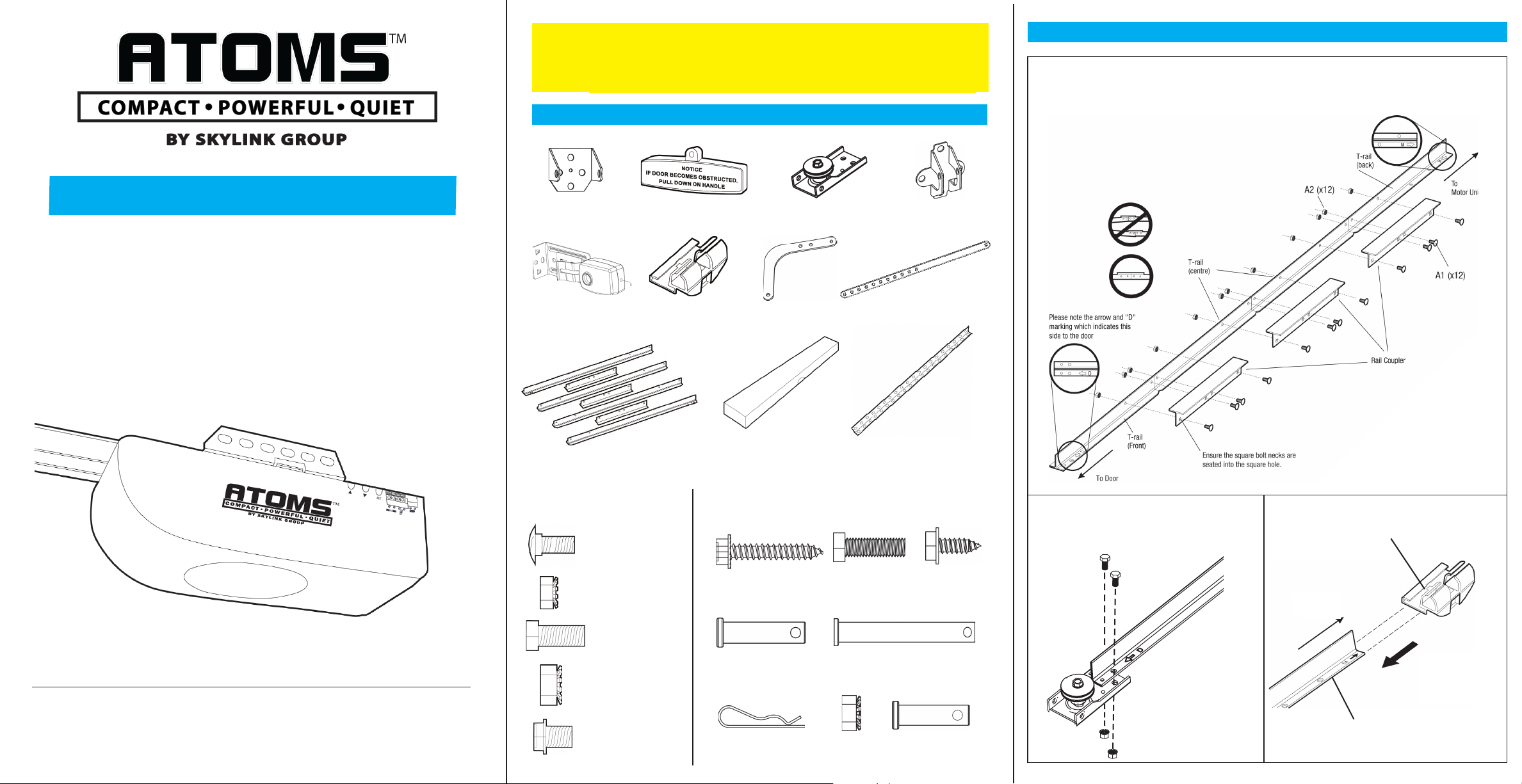
B. Assemble the T-Rail
1. Connect the T-Rail Sections
Align the 4 T-Rail sections on the oor. Connect these
rails together with the rail couplers as shown.
All rail pieces must be aligned properly.
Please note the arrow and
“M” marking which indicates
this side to the motor M unit.
Quick Guide
Garage Door Opener
Chain Accessory Kit
Model: AT-200C
www.skylinkhome.com
Congratulations on your purchase of Skylink Model AT-200C Hardware kits.
Please follow the instructions to assemble the rail sections and setup the safety
beam sensor. FOR HELP
1-800-304-1187 or Email: support@skylinkhome.com.
Head Bracket
Safety Beam Sensor
Rail Sections
BAG A
A3 x 2
Bolt
A1 x 12
Carriage Bolt
A2 x 12
Locknut
A4 x 3
Locknut
A5 x 3
Flange Bolt
Handle
Trolley
Chain and Cable
Assembly
BAG B
B1 x 4
Lag Screw
B4 x 1
Clevis Pin
B6 x 3
Hitch Pin
Pulley Assembly
Curved Arm
B2 x 4
B8 x 4
Locknut
Straight Arm
Hanging Brackets
Bolt
B5 x 1
Clevis Pin
Door Bracket
B3 x 2
Self-Tapping Screw
B9 x 1
Clevis Pin
2. Attach the Pulley Assembly
Attach the tensioner pulley Assembly to
the end of the front rail with 2 nuts and bolts.
A3 x 2
^ P
Align the Pulley
Bracket & Rail
A4 x 3
3. Install the Trolley
Ensure this side of the trolley is on the stop bolt
hole side of the rail.
To Motor
Unit (Back)
Slide the trolley
from the back of
the T-rail
assembly.
Stop Bolt
Hole.
Page 2

B. Assemble the T-Rail (continued)
C. Install Safety Beam Sensor
C. Install Safety Beam Sensor (continued)
4. Attach the T-Rail to the Opener
Raise the pulley end of the rail so the rail can
sit on the motor unit properly. Attach the rail to
the motor unit by tightening 2 screws. Insert a
bolt to the stop bolt hole and secure it with nut.
6. Place the Cable on the Pulley
Place the cable around the pulley at the end of the rail. Ensure chain/cable passes through the
trolley guides. Insert the trolley guides into the chain traveller until you hear a click when the
chain traveller is completely seated into the trolley.
5. Align the Chain on the Sprocket
Start aligning the chain by placing the turnbuckle
10” (25 cm) from the sprocket. Wrap the chain
around the sprocket. The sprocket teeth must
engage the chain as shown.
Important Information
The safety beam sensor can detect obstacle in the path of its invisible beam. When the
beam is obstructed while the door is closing, the door will stop immediately and reverse
to the fully open position, and the opener lights will ash. It is important to ensure the
invisible infrared beam must be unobstructed by any part of the garage door, door
tracks, other hardware or objects near the garage door.
Note: Refer to the Owner’s Manual to align the Safety Beam Sensor
1. Identify the Transmitter and the
Receiver.
The unit has red LED is the transmitting
sensor. The unit has blue LED is the receiving sensor. Avoid sun light shining directly
into the receiving sensor.
Note: Refer to the Owner’s Manual to mount the Safety Beam Sensor on the
wall or oor (optional).
3. Route & Secure the Sensor Wires
Run the wires up the wall, then over to
the center of the door. Secure the wires to
the wall with wire holders. Run the wires
along the top of the T-rail and secure them
with 4 wire clips (option).
4. Connect the Wires to the Opener
Run the wires up the wall, then over to
the center of the door. Secure the wires to
the wall with wire holders. Run the wires
along the top of the T-rail and secure them
with 4 wire clips (option).
Black White
Note: For detail assembly procedure, please refer to Owner’s Manual.
Note: Receiving sensor has a label
marking “Receiver” on the wire.
2. Mounting the Sensor on the Door
Track
Slide the mounting bracket onto the garage
door track and secure on the door track.
Ensure the sensor is no higher than 4 inch-
es (10cm) above the oor. Follow the same
procedure to install the sensor on the other
tracker. Ensure they are on the same level
facing each other.
If you have any questions, problems or missing parts,
please call Skylink Customer Support:
9:00am - 5:00pm EST, Monday - Friday.
1-800-304-1187
Or e-mail us at support@skylinkhome.com
www.skylinkhome.com
Customer Service, 17 Sheard Avenue, Brampton, Ontario, Canada, L6Y 1J3
© 2016 SKYLINK GROUP P/N: 101Y332
 Loading...