


www.skylinkhome.com
Emergency Dialer
DIAL-ALERT TM
MODEL: AD-105
If you would like to order Skylink’s products or have difficulty getting them to work or download information and user manual, please :
1.visit our FAQ section at www.skylinkhome.com, or
2.email us at support@skylinkhome.com, or
3.call our toll free at 1-800-304-1187 from Monday to Friday, 9 am to 5 pm EST.
Fax (800) 286-1320
CUSTOMER SERVICE
|
|
17 Sheard Avenue, Brampton, Ontario, Canada L6Y 1J3 |
|
|
|
Tel : (800) 304-1187 |
|
101Z857-001 |
OCT, 2010 |
Fax : (800) 286-1320 |
PAT. D410633 |
Email : support@skylinkhome.com |
6243000B1 |
SKYLINK TECHNOLOGIES INC.
Your Guide to the
Emergency Dialer
DIAL-ALERTTM
MODEL: AD-105
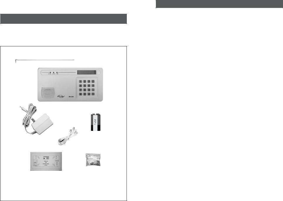
The AD-105 Emergency Dialer contains all the above items.
TABLE OF CONTENTS |
|
PACKAGE CONTENTS............................................................................................ |
4 |
OVERVIEW..................................................................................................... |
5-6 |
INSTALLATION.............................................................................................................. |
7-9 |
LIGHTSAND SOUNDS....................................................................................................... |
10 |
STANDARD PROGRAMMING................................................................................... |
11-15 |
-Selecting the Operation Mode........................................................................ |
11 |
-Recording a Voice Message.............................................................................. |
12 |
-Message Playback........................................................................................ |
13 |
-Program a Phone Number................................................................................ |
13 |
-Program a sensor under sensor operating mode............................................. |
15 |
-Testing............................................................................................................... |
15 |
OPERATIONS..................................................................................................... |
16-17 |
-SC-001 Mode....................................................................................................... |
16 |
-Sensor Mode............................................................................................ |
16 |
-Receiving a phone call............................................................................. |
16 |
ADVANCED PROGRAMMING................................................................................... |
18-22 |
-Changing Password........................................................................................... |
18 |
-Program the Calling Time........................................................................... |
18 |
-Erase programmed Panic Transmitters/Alarm Panels/Sensors...................... |
19 |
-Dial Sequence Setting..................................................................................... |
19 |
-Universal Dial Tone.............................................................................................. |
19 |
-Pick up Pause Period ..................................................................................... |
20 |
-Entry/Exit Delay - For Sensor Mode.................................................................... |
20 |
-Arming/Disarming.............................................................................. |
21 |
CONNECT THE DIAL-ALERT WITH YOUR EXISTINGALARM SYSTEM................. |
22 |
QUICK GUIDE......................................................................................................... |
22 |
BATTERY MAINTENANCE................................................................................. |
23 |
-Dial-Alert Battery........................................................................................................... |
23 |
ADDITIONALACCESSORIES................................................................................ |
24-26 |
–2– |
–3– |
PACKAGE CONTENTS
All materials required for installation are included with this package
1 Dial-Alert (AD-105)
1 Telephone Line
1 antenna (installed)
1 AC adapter
1 9 volt alkaline battery
1 Pack of screws and anchors (for Dial-Alert) One template
Double sided tape User's instructions Warranty Card Quick Guide
–4–
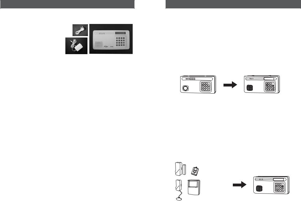
OVERVIEW
The AD-105 emergency dialer can call multiple phone numbers during an emergency situation and it will playback prerecorded messages. There are 2 operating modes you can set up in the AD-105 dialer.
SC-001 Mode - Works with SC-001
You can setup the AD-105 to communicate with a control panel SC-001, so when the SC-001 alarm is activated, it will send a panic signal to the dialer and it will call you and other phone numbers (up to 9 phone numbers) and then playback a 40-second pre-recorded message.
|
|
|
905-608-9223 |
|
|
|
A |
|
|
|
|
B |
|
|
* |
# |
C |
* |
# |
|
|
Panic |
|
|
SC-001 |
|
Signal |
AD-105 |
|
Sensor Mode - Works with multiple sensors directly
You can program sensors directly to the AD-105 so when any one of the sensors is triggered, the dialer will dial the programmed phone numbers and playback voice messages. It is possible to record one primary voice message and up to 6 unique messages, these unique messages will be sensor specific.
905-608-9223
Various |
Sensor |
* |
# |
…Sensor |
|
|
|
Activation |
AD-105 |
|
|
|
Signal |
|
|
|
|
|
–5–
OVERVIEW
Dial Alert AD-105 must work with the specific sensors listed below. Ensure only the listed sensors are used with the AD-105, otherwise, the communication between the sensors and the Dial Alert may not function properly. If you have a Skylink wireless device or sensor that is not listed below, and uncertain whether it can work with your AD-105, please contact our customer support team.
You can program the following sensors and accessories to the dialer, they are fully compatible with Dial Alert AD-105:
Panic Devices |
|
|
|
|
|
4-Button Transmitter: |
4B-101, 4B-434 |
|
|||
Panic Transmitter: |
PT-434, HW-434 |
|
|||
Keypad Transmitter: |
KP-434 |
|
|||
Control Panel: |
SC-001 |
|
|||
Sensors |
|
|
|
|
|
Door Window Sensor: |
|
|
|
Flood Sensor: |
|
|
|
|
|
||
WD-101 |
|
|
|
FS-101 |
|
Motion Sensor: |
|
|
|
Audio Sensor: |
|
|
|
|
|
||
|
|
|
|
||
PS-101 |
|
|
|
|
|
|
|
|
AS-101 |
|
|
Temperature Sensor: |
|
|
|
|
|
|
|
|
|
|
|
TS-101A |
|
|
|
Garage Door |
|
Vibration Sensor: |
|
|
|
MonitorTM Sensor |
|
|
|
|
GS-101 |
|
|
VS-101 |
|
|
|
|
|
|
|
|
|
|
|
There are 2 types of sensors and accessories.
Panic Devices - These are devices such as 4-Button Transmitter, Panic Transmitter and Keypad Transmitter. When the panic button on these transmitters is activated, the Dial Alert will dial out regardless whether it is in armed or disarmed mode.
Sensors - These sensors will only trigger the Dial Alert if it is armed. If the Dial Alert is not armed, the Dial Alert will not be activated even if the sensors are triggered. If you have sensors installed, ensure you arm the Dial Alert if you want to be notified by sensor activation.
Please refer to the programming instructions “STANDARD PROGRAMMING” to
set up the operation mode of your emergency dialer.
–6–
INSTALLATION
The Dial-Alert is installed using the screws provided. We have also included double sided tape, to use for temporary installation while you are positioning the dialer. Once the dialer is positioned correctly, install it permanently with screws. We have also included wall anchors and a template to help position the screws correctly.
How to use the template:
1.Cut the template in the correct position
2.Screw part way into the surface where the holes are marked
3.Unscrew the screws and remove the template
4.Screw the component in place where you started the screws
INSTALLING THE DIAL-ALERT (AD-105)
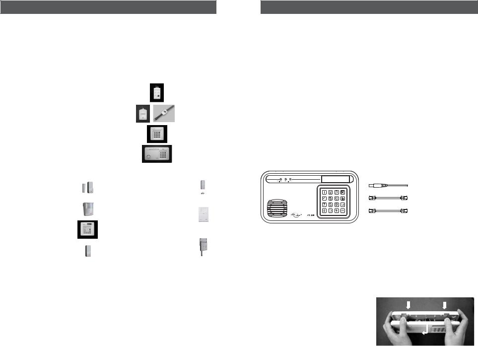
Position the dialer beside a telephone or near any phone line and within access of an electrical outlet. However, it is recommended that you hide the dialer for security purposes. The dialer runs on regular electrical current. It also contains a 9 volt backup battery in case power is interrupted for any reason. A phone line must be connected to the dialer in order for the dialer to work. Connect the phone lines and AC adapter as shown.
905-456-8883 |
12V DC |
|
|
|
|
|
|
AC ADAPTER |
|
|
OPTIONALLINEINPUTFOR |
|
PHONE |
ANSWERINGMACHINE/TELEPHONE |
TEL LINE IN
LINE
Note: The optional line input is intended for an answering machine, telephone etc. The device connected to the dialer will be disconnected when the dialer is activated. Therefore it will not affect the operation of the dialer.
There are 3 ways to attach the Dial-Alert on the wall:
1.Using double sided tape for temporary use.
2.Hanging it from the two keyholes on two stationary screws.
3.Screwing the back onto the wall with four screws.
To mount the Dial-Alert:
1.Open the case.
a) Press the two tabs on top of the
dialer.
b) Pull open the front.
–7–

INSTALLATION
2.Thread the telephone line through the top hole in the back of the unit and plug it into the "LINE" jack. If you want to have an answering machine on the same line as the dialer, thread the phone line through the bottom hole in the back of the unit and plug it into the "PHONE" jack of the dialer. The phone line(s) must be inserted through the back of the unit before it is attached to the wall.
3.Thread the AC adapter cord through the top hole in the back of the unit and plug it into the AC connector on the circuit board as shown. The adapter cord must be inserted through the back of the unit beforeit is attached to the wall.
4.Insert the 9 volt battery and rotate the antenna from the inside of the dialer to the outside.
5.Firmly close the case. Insert and secure the two screws to the bottom case near the two tabs.
6.Using the template provided, insert the two screws into the wall.
7.Gently hang the Dial-Alert to these two screws.
8.Plug the other end of the telephone cord into a telephone jack. Plug the AC adapter into a power outlet. The red AC PWR light will turn on and the keypad backlight will be on.
NOTE: After installation, please use two screws (included) to fix the front and back case together before hanging on to the wall. (When you open the case, please remove the AC adapter
and the phone line from the wall outlet).
–8–
INSTALLATION
Speaker On/Off Switch
The speaker must be on during programming and recording the voice message in order to use the playback feature. For security purposes, the speaker may be turned off after programming to allow for silent dialing when the dialer is activated.
The On/Off switch for the speaker is located on the lower right corner of the circuit board. The default setting for the speaker is "On".
–9–
 Loading...