

Page 1
www.skylinkhome.com
Emergency Dialer
TM
DIAL-ALERT
MODEL : AD-433S
English
101A320
JUNE, 2004
CUSTOMER SERVICE
17 Sheard Avenue, Brampton, Ontario, Canada L6Y 1J3
Tel : (800) 304-1187
Fax : (800) 286-1320
Email : support@skylinkhome.com
PAT. D410633
6243000B1
Page 2
SKYLINK TECHNOLOGIES INC.
9 VOL
T
–2–
Your Guide to the
Emergency Dialer
English
Emergency Dialer
DIAL-ALERT
AD-433S
TM
DIAL-ALERT
MODEL: AD-433S
TM
USER'S INSTRUCTIONS
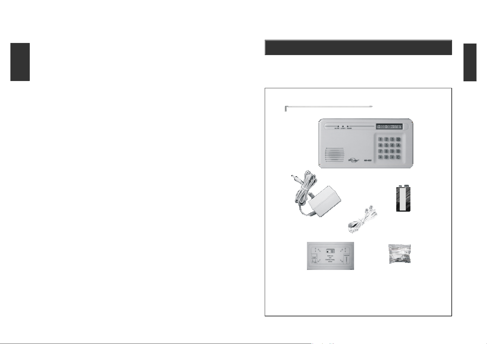
The AD-433S Emergency Dialer contains all the above items.
Page 3

TABLE OF CONTENTS
–3–
PACKAGE CONTENTS
PACKAGE CONTENTS............................................................................................4
...
OVERVIEW.........................................................................................................5
INSTALLATION.......................................................................................................................6
LIGHTS AND SOUNDS.........................................................................................................9
STANDARD PROGRAMMING...................................................................................10-14
-Program the Time Clock...............................................................................................10
-Recording a Message....................................................................................................10
-Playback Pre-recorded Message................................................................................11
-Storing Telephone Numbers.........................................................................................11
- A. Storing telephone numbers in memory
(Sends the emergency voice message only)......................................11-12
- B. Storing telephone numbers in memory
(Sends both emergency voice message and numeric information)........12
- C. Storing telephone numbers in memory
(Sends the numeric information to pager only)..............................................13
-Delete A Telephone Number From Memory...............................................................13
-To Review or Modify the Pre-programmed Phone Numbers, The
Redial Count and/or The Repeat Times of a Phone Number...............................14
-Activate the Dial-Alert with The Panic Button on the Keypad...............................14
ADVANCED PROGRAMMING...................................................................................15-20
-Program the calling time...........................................................................................15
-Programming a Pause Period...........................................................................15
-Set the type of Phone System.....................................................................................16
-Program the ID Code of a Transmitter....................................................................17
-Delete Programmed Transmitters/Sensors/Security Systems......................17
-To Arm/Disarm the Dialer.....................................................................................18
-Delay Dialing (Entry/Exit Mode)................................................................................18
-Universal Dial Tone..............................................................................................19
-Dial Sequence Setting.....................................................................................20
All materials required for installation are included with this package
1 Dial-Alert (AD-433S )
1 Telephone Line
1 antenna (installed)
1 AC adapter
1 9 volt alkaline battery
1 Pack of screws and anchors (for
One template
Double sided tape
User's instructions
Warranty Card
Quick Guide
Dial-Alert)
CONNECT THE DIAL-ALERT WITH YOUR EXISTING ALARM SYSTEM............21
QUICK GUIDE.........................................................................................................22
BATTERY MAINTENANCE.................................................................................23
-Dial-Alert...........................................................................................................................23
ADDITIONAL ACCESSORIES................................................................................24-26
Page 4
–5–
OVERVIEW
–6–
INSTALLATION
Automatically call for help when emergency
The AD-433S Dial-Alert dials as many as 9 pre-programmed telephone numbers
and sends a personalized pre-recorded message. Each telephone number
can be dialed up to 9 times and the person receiving the emergency message
can confirm receipt of that message by pressing the "#" key on their telephone.
A pre-recorded message, maximum 40 seconds in length will be played
notifying the person being called of the emergency.
The Dial-Alert works in conjunction with Skylink's Security Systems (SC-5,
SC-10, SC-100 s eries, SC-200 series) and all the Skylink Sensors / Transmitters.
When the alarm sounds on the control panel on any of our security systems,
the Dial-Alert will be activated .
The Dial-Alert is activated when:
1. The red panic button [O] on the keypad of the Dial-Alert is pressed
2. The button is pressed on the panic transmitter (PT-434*, sold separately)
3. The red panic button [O] on the keypad of our security system (SC-100) is
pressed *
4. The red button on the keychain transmitter (4B-434)* is pressed
5. The security system SC-100/SC-200 is activated by any programmed
sensors (i.e. door/window sensor, motion sensor, etc.)
* The security systems, keychain transmitters and sensors must first be
programmed to communicate with the Dial-Alert.
This user's instructions is divided into 4 sections in order to assist in the
installation and programming of your Dial-Alert.
1. Installation
2. Lights and Sounds
3. Standard Programming
- Program the time clock
- Record a message
- Playback of pre-recorded message
- Storing telephone numbers in memory for
- emergency voice message only
- both emergency voice message and numeric pager information
- numeric pager information only
- Delete a telephone number from memory
- Modify a telephone number, the redial count and repeat times of a phone number
4. Advanced Programming
- Programming the calling time
- Programming the pause period for pager access and telephone numbers
- Select the phone system (regular or PABX phone systems)
- Program transmitters / accessories to activate dialer
- Erase programmed transmitters / accessories
- To arm / disarm the dialer
- Dialing delay
- Universal Dial Tone
The Dial-Alert is installed using the screws provided. We have also included
double sided tape, to use for temporary installation while you are positioning
the dialer. Once the dialer is positioned correctly, install it permanently with
screws. We have also included wall anchors and a template to help position
the screws correctly.
How to use the template:
1. Cut the template in correct position
2. Screw part way into the surface where the holes are marked
4. Unscrew the screws and remove the template
5. Screw the component in place where you started the screws
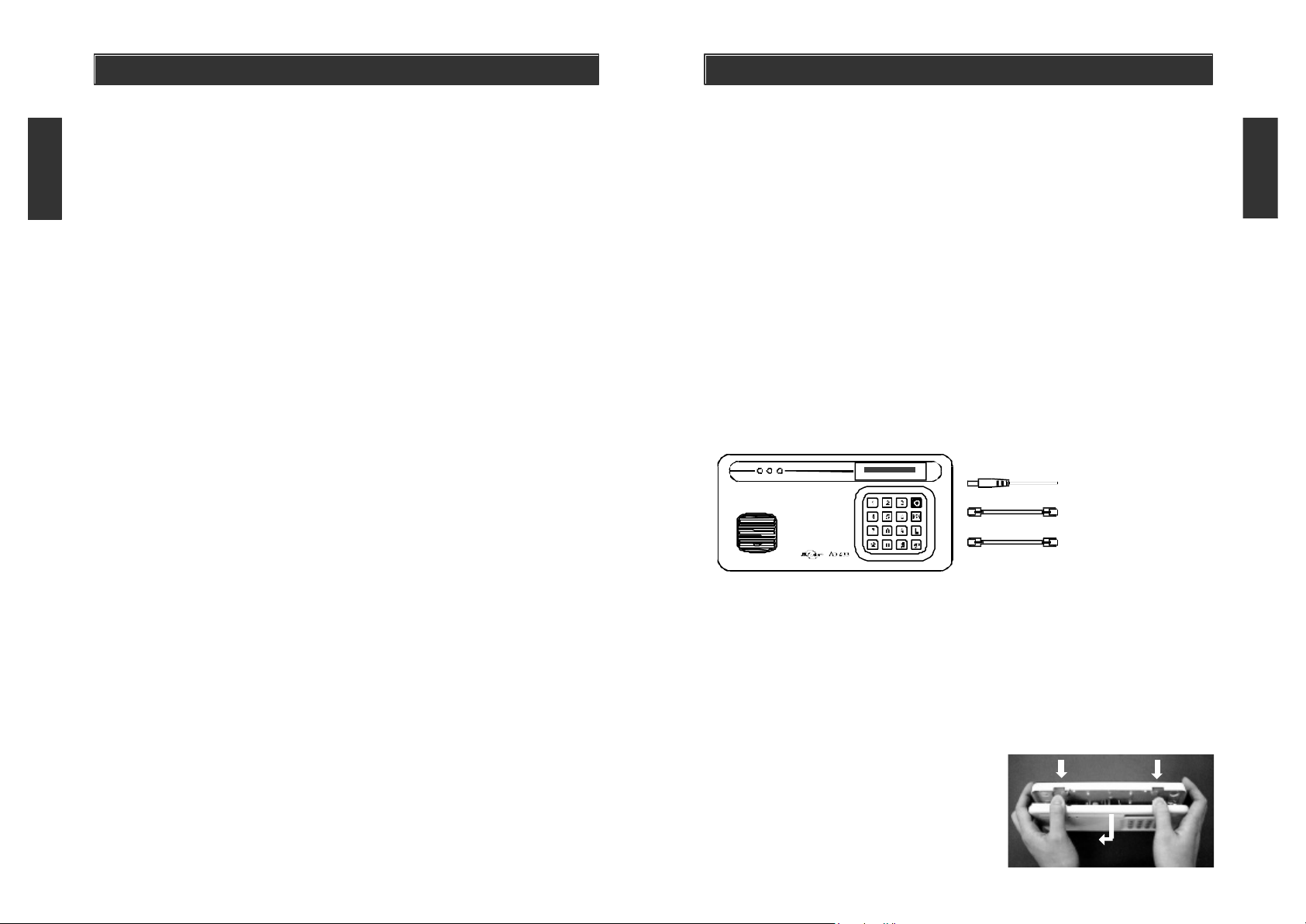
INSTALLING THE DIAL-ALERT (AD-433S)
Position the dialer beside a telephone or near any phone line and within
access of an electrical outlet. However, it is recommended that you hide the
dialer for security purposes. The dialer runs on regular electrical current. It
also contains a 9 volt backup battery in case power is interrupted for any
reason. A phone line must be connected to the dialer in order for the dialer
to work. Connect the phone lines and AC adapter as shown.
12V DC
PHONE ANSWERING MACHINE / TELEPHONE
LINE
Note: The optional line input is intended for answering machine, telephone etc. The device connected to the dialer will be disconnected when
the dialer is activated. Therefore it will not affect the operation of the dialer.
There are 3 ways to attach the Dial-Alert on the wall:
1. Using double sided tape for temporary use.
2. Hanging it from the two keyholes on two stationary screws.
3. Screwing the back onto the wall with four screws.
AC ADAPTER
OPTIONAL LINE INPUT FOR
TEL LINE IN
To mount the Dial-Alert:
1. Open the case.
a) Press the two tabs on top of the
dialer.
b) Pull open the front.
Page 5
–7–
INSTALLATION
–8–
INSTALLATION
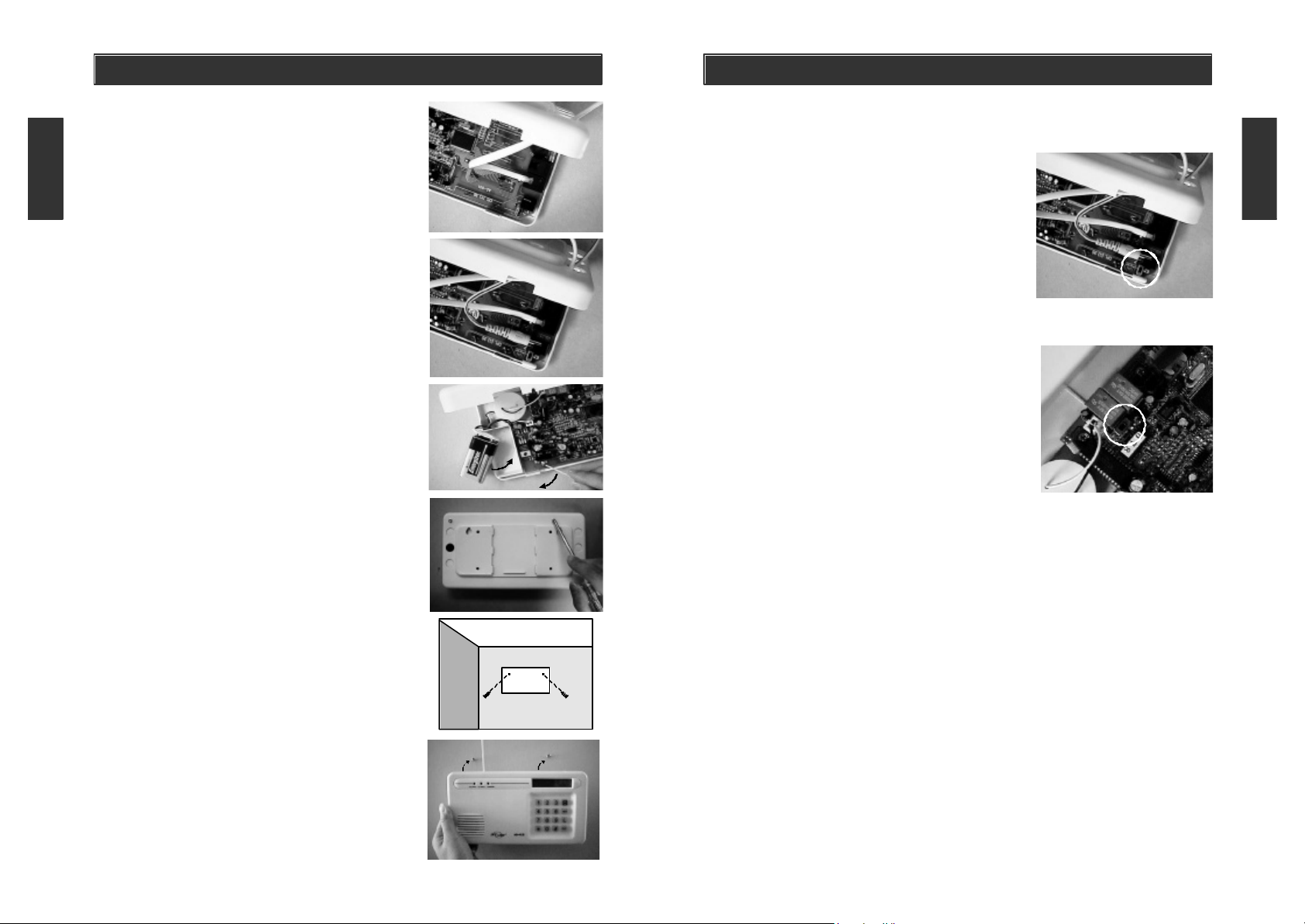
2. Thread the telephone line through the top
hole in the back of the unit and plug it into
the "LINE" jack. If you want to have an
answering machine on the same line as
the dialer, thread the phone line through the
bottom hole in the back of the unit and plug
it into the "PHONE" jack of the dialer. The
phone line(s) must be inserted through
the back of the unit before it is attached
to the wall.
3. Thread the AC adapter cord through the top
hole in the back of the unit and plug it into
the AC connector on the circuit board as
shown. The adapter cord must be inserted
through the back of the unit beforeit is
attached to the wall.
4. Insert the 9 volt battery and rotate the
antenna from the inside of the dialer to
the outside.
5. Firmly close the case. Insert and secure the
two screws to the bottom case near the two
tabs.
6. Using the template provided, insert the two
screws into the wall.
7. Gently hang the Dial-Alert to these two
screws.
Switch Setting
1. Tone/Pulse Switch
This dialer supports both Tone and Pulse
dialing. In order to change the setting, you
need to open the case by pressing the two
tabs on top of the dialer and pull open the front.
The Tone/Pulse switch is located at the upper
left corner of the circuit board (just above
the adapter jack). The switch is set to Tone at
the factory. This setting can be changed by
sliding the switch to the appropriate position.
2. Speaker On/Off Switch
The speaker must be on during programming
and recording the voice message in order to
use the playback feature. For security purposes, the speaker may be turned off after
programming to allow for silent dialing when
the dialer is activated.
The On/Off switch for the speaker is located
on the lower right corner of the circuit board.
The default setting for the speaker is "On".
8. Plug the other end of the telephone cord into
a telephone jack. Plug the AC adapter into a
power outlet. The red AC PWR light will turn
on and the keypad backlight will flash.
CAUTION: After installation, please use two
screws (included) to fix the front and back case
together before hang on to the wall. (When you
open the case, please remove the AC adapter
and the phone line from the wall outlet).
Page 6

–9–
LIGHTS AND SOUNDS
STANDARD PROGRAMMING
Below is an explanation of the lights and sounds of the Dial-Alert
LIGHTS
ACPWR light on dialer is being powered by AC adapter.
ACPWR light off dialer is not receiving any AC power.
LOBATT. light off backup battery is connected and working.
LOBATT. light on backup battery is weak, battery needs to be replaced.
DISARM light off the dialer will dial the pre-programmed phone numbers
when activated.
DISARM light on the dialer will not dial any phone numbers when
activated.
Keypad backlight 1.) The dialer has no message in memory.
flashing 2.) Dial tone is not detected when the dialer is
activated, check phone line connection.
Keypad backlight If unit is powered by AC adapter or powered by back
up battery, back light stays on for five seconds
when any key on the keypad is pressed.
SOUNDS
Short beep You have pressed a key in the right order.
Two short beep's 1.) When the dialer is turned on for the first time.
2.) When the pre-programmed transmitters/sensors
are deleted from the memory.
Long beep You have made a mistake.
Steady repeated beep The dialer has been triggered in DELAY mode. It
gives you time to disarm the dialer before dials the
emergency phone number.
When you plug in the dialer for the first time, you will hear a double beep and
all the lights will be on for 2 seconds, the keypad will continue to flash and
the clock will be set to 12:00.
PROGRAM THE TIME CLOCK
1. Press the [L] key, display will show “L”.
2. Press the [4] key, display will show “ L 4 12:00 ”. The first digit of
the time will be flashing. The flashing digit is the number you are currently
changing.
3. Using the keypad, enter the desired number.
The clock is in 24 hour mode. For example, if the display shows
“ L 4 1330 ”, the time is set at 1:30 pm.
To change the time to 8:15 pm, the sequence is (remember that the clock is
in 24 hour mode):
[ L ] , [ 4 ] , [ 2 ] , [ 0 ] , [ 1 ] , [ 5 ]
RECORDING A MESSAGE
Currently the keypad is flashing and will continue to flash until a message
has been recorded. The dialer cannot dial any phone numbers if a message
has not been recorded.
To record a voice message, press and hold the [R/P] key for 2 seconds, the
display will show “rEcord” and a beep is generated which alerts you to begin
recording. The microphone is located beside the speaker. Record all the information you would like to be played in case of an emergency. For example:
"This is an emergency voice message, my name is John Smith, please send
help, I live at......My phone number is xxx-xxx-xxxx" (if you have two phone
lines, give the phone number of the line that the dialer is not using.)
This dialer includes a special feature to let the called party terminate the emer-
gency message. By pressing "#" while the message is being played, the Dialer
will stop calling that number, then advance to the next number, if any. We recommend that a short ending be recorded after the emergency message informing
the recipient of this feature (i.e. this message will call you x times and repeat x
times during each call, to acknowledge and discontinue further calls, press "#").
After you are finished recording the message, (maximum length of 40 seconds),
press [R/P] key, display will show “PLAY” and play back the message. After
playing the message, the display will return to clock mode. The keypad backlight will stop flashing indicating that a message has been recorded.
The sequence to record a message is:
Press and hold [ R/P ] for 2 seconds , [ record message ] , press [ R/P ].
Page 7

STANDARD PROGRAMMING
–12–
STANDARD PROGRAMMING
PLAYBACK PRE-RECORDED MESSAGE
Press and release the [R/P] key, display will show “PLAY” and the dialer will
beep. The message is then played back.
If you want the dialer work without noise, means no beep or let no body knows
the dialer is dialing, just turn off the Speaker Switch inside the case.
STORING TELEPHONE NUMBERS
This feature enables the user to program as many as 9 different telephone
numbers. The dialer can send out 2 different messages. One message is the
pre-recorded voice message that you programmed earlier, the other message
sends numeric information to a pager.
There are three different ways that you can send the voice message and the
numeric information:
A. Sends the emergency voice message only
B. Sends both the emergency voice message and the numeric infomation
(pager reception only)
C. Sends the numeric information only (for pager reception only)
Cautions:
Skylink recommends that the telephone or pager numbers of your relatives,
neighbors, office/work, friends or doctor be programmed into your Dial-Alert. Do
not program the phone number to police or fire dept directly into your Dial-Alert
unless you have checked with your local authorities. Please also inform all the
recipients that their phone numbers have been programmed into your dialer, so
they know exactly what happen when they receive your emergency message.
A. Storing telephone numbers in memory (Sends the emergency
voice message only)
1. Press the [MEM] key, the display will show a letter “M” on the upper left corner.
If nothing is entered within 5 seconds, the display will return to the clock mode.
2. Within the first 5 seconds, select a memory location by pressing a key
pad number 1 - 9 to store the telephone number.
3. Enter the telephone number using the keypad. The display will flash as the
numbers are being entered. To insert a pause period between any digits of
the pre-programmed telephone number, see PROGRAMMING A PAUSE
PERIOD (page 15).
4. Press the [MEM] key within 5 seconds after the last digit of the telephone
number is entered. The number is now stored.
5. After the telephone number has been stored, "rEdIAL 3" will appear on the
display. This is the redial count which is the number of times the dialer will
call that telephone number. The dialer is factory set to call each number 3
times. The number of attempts can be changed to dial 1 to 9 times. If you
want to keep the dialer at 3 attempts, press the [MEM] key. To change the
redial count, enter a number from 1 - 9 when display shows “rEdIAL 3” .
6. The display will now show “rEPEAt 3”. This is the repeat count which is
the number of times the message will be repeated during that one call. The
dialer is factory set to repeat the message 3 times. The number of repeats
can be changed from 1 to 9 times. If you want to keep the repeat count to
remain at 3 times, press the [MEM] key. To change the repeat count, enter
a number from 1 - 9 when display shows “rEPEAt 3” .
7. The dialer is now in standby mode. (Display shows the time).
The sequence to store a telephone number is as follows:
[MEM] , enter memory location (1-9) , enter telephone # , [MEM] , enter
redial # (1-9), enter repeat # (1-9).
B. Storing telep hone nu mbers in memory (Sends both emergency
voice message and numeric information)
1. Press the [MEM] key, the display will show a letter “M” on the upper left
corner. If nothing is entered within 5 seconds, the display will return to
the clock mode.
2. Within the first 5 seconds, select a memory location by pressing a keypad
number 1 - 9 to store the telephone number.
3. Enter the telephone number using the keypad. The display will flash as the
telephone is being entered. To insert a pause period between any digits
of the pre-programmed telephone number or after the telephone number
and before the numeric message. (used for pagers), see PROGRAMMING
A PAUSE PERIOD (page 15).
4. Press [MEM].
5. "rEdIAL 3" will appear on the display. This is the redial count which is
the number of times the dialer will call that telephone number. The dialer
is factory set to call the number 3 times. The number of attempts can
be changed to dial 1 to 9 times. If you want to keep the redial count at 3
attempts, press the [MEM] key. To change the redial count, enter a number
from 1 - 9 when display shows “rEdIAL 3”.
6. The display will now show “rEPEAt 3”. This is the repeat count which is
the number of times the message will be repeated during that one call.
The dialer is factory set to repeat the message 3 times. The number of
repeats can be changed from 1 to 9 times. If you want to keep the repeat
count to remain at 3 times, press the [MEM] key. To change the repeat
count, enter a number from 1 - 9 when display shows “rEPEAt 3”.
Page 8

–13–
STANDARD PROGRAMMING
–14–
STANDARD PROGRAMMING
C. Storing telephone numbers in memory (Sends the numeric
information to pager only)
1. Press the [MEM] key, the display will show a letter “M” on the upper left
corner. If nothing is entered within 5 seconds, the display will return to the
clock mode.
2. Within the first 5 seconds, select a memory location by pressing a keypad
number 1 - 9 to store the telephone number.
3. Enter the telephone number using the keypad. The display will flash as the
telephone is being entered. To insert a pause period between any digits
of the pre-programmed telephone number or after the telephone number
and before the numeric message. (used for pagers), a pause period must
be adde d between the telephone number and the numerical message. Refer
to the Pager Company to identify the pause needed (see PROGRAMMING
A PAUSE PERIOD - page 16).
4. Enter the numeric information you want to send out, ( the information that
will be shown on the pager), then press [L]. This will suspend the recorded
message.
5. Press [MEM].
6. After the telephone number has been stored, another message will appear
on the display asking for a redial count. The redial count is the number
of times the dialer will call that telephone number. The dialer is factory set
to call the number 3 times. The number of attempts can be changed to dial
1 to 9 times. If you want to keep the redial count at 3 attempts, press the
[MEM] key. To change the redial count, enter a number from 1 - 9 when
display shows "rEdIAL 3".
7. Input the repeat times when the display shows "rEPEAt 3". The repeat
time is the number of times the message will be played for that certain
phone number. The current setting is 3. It can be changed from 1 to 9 using
the keypad. Again, by pressing [MEM] will keep the existing setting.
TO REVIEW OR MODIFY THE PRE-PROGRAMMED PHONE NUMBERS, THE REDIAL COUNT AND/OR THE REP EAT TIMES OF A
PHONE NUMBER.
1. Press the [MEM] key, display will show an “M” in the upper right corner.
2. Select the memory location of the phone number, (1 - 9)
3. Th e phone number will be shown on the display.
4. If you want to change the telephone number, enter the new phone number
while the old number is on the screen . This telephone number will be deleted
when a new number is added. Then press the [MEM] key. If you want to
keep the telephone number shown on the screen, press [MEM].
5. The display will now show the current setting of the redial count. If you
want to keep the current redial count, enter the [MEM] key. If you want
to change the setting, enter the desired number, (1 - 9), then press the
[MEM] key.
6. After pressing the [MEM] key, the display will show the current setting
of the repeat times.
7. If you want to keep the current repeat time, enter the [MEM] key. If you
want to change the setting, enter the desired number, (1 - 9), then press
the [MEM] key.
8. The screen will revert back to clock mode.
ACTIVATE THE DIAL-ALERT WITH THE PANIC BUTTON ON THE
KEYPAD
After you programmed all the emergency telephone numbers and the voice
message, you can activate the dialer by pressing the panic button on the
keypad. Once the panic button is pressed, the dialer will start dialing the preprogrammed emergency phone numbers. You can also activate the dialer
using the Panic Transmitter. (PT-434, sold separately).
DELETE A TELEPHONE NUMBER FROM MEMORY
1. Press [MEM] key.
2. Select the memory location (1 - 9) of the phone number you want to delete.
3. The phone number will be shown on the display, if that is the number you
want to delete, press the [R/P] key while the telephone number is on the
display. Once the phone number is deleted, the display will return to clock
mode.
Page 9

–15–
ADVANCED PROGRAMMING
ADVANCED PROGRAMMING
PROGRAM THE CALLING TIME
The calling time is the amount of time the phone will ring until the call is discontected. If the phone is not picked up within this period of time, the dialer
will either call again, (depends on the redial count), or advance to the next phone
number. The calling time is currently set at 60 seconds.
How to program the calling time.
1. Pres s the [L] key, the display will show “ L ”
2. Press the [1] key, the diplay will show “ L 1 1 ”, the last digit, “ 1 ”, is
the setting of the call time, (in this example, it is currently 30 seconds,
as per chart below). To keep this setting, press the [L] key.
3. To change the calling time, press either 1, 2, 3, 4 or 5 when the diplay
shows “ L 1 1 ” (refer to the chart below)
1 = 30 seconds
2 = 45 seconds
3 = 60 seconds
4 = 75 seconds
5 = 90 seconds
If the display shows “ L 1 3 ”, the phone will ring for 60 seconds before
the call is disconnected.
PROGRAMMING A PAUSE PERIOD
When storing a phone number, you are able to insert a pause period between
any digits of the phone number or after the phone number and before the
numeric message (for pagers).
To set the pause period for pagers numeric message
1. Press the [L] key, the display will show “ L ”
2. Press the [2] key, the display will show “ L 2 5 ”, the last digit, “ 5 ”,
is the setting of the pause period (in this example, it is currently set at 5
seconds), to keep this setting, press the [L] key.
and before you can enter the numeric information (i.e. phone number). The
display will show a "P" if a pause period is entered. This pause period is
factory set at 5 seconds but can be changed from 1 - 9 seconds. You may
also insert multiple pause periods to suit your application. Call the paging
company to determine how long the pause period should be.
To insert a pause period in a telephone number
The length of the pause period [L*] can be programmed as shown.
1. Press the [L] key, the display will show "L".
2. Press the [ * ] key, the display will show "L* 3", the last digit, "3", is the
setting of the pause period, (in this example, it is currently set to 3
seconds, as per chart below). To keep this setting, press the [L] key.
3. To change the pause period, press either 1, 2.....or 9 when the display
shows "L* 3".
1 = 1 second 2 = 2 seconds 3 = 3 seconds
4 = 4 seconds 5 = 5 seconds 6 = 6 seconds
7 = 7 seconds 8 = 8 seconds 9 = 9 seconds
When programming a telephone number to the dialer, (see STORING TELEPHONE NUMBERS), a pause period may be added between any digits of a
phone number. By using the " * " key on the keypad, a pause period will be
entered. The pause period will be anywhere between 1-9 seconds, (see the
beginning of this section to set the length of the pause period). Example, if
you wanted a pause between the third and forth number, the sequence would
go as follows, 568*2095. If the pause period was set at five seconds, there
would be a five second delay between the 8 and the 2.
SET THE TYPE OF PHONE SYSTEM
This dialer supports both regular telephone and PABX phone systems.
Selection can be made using the function key. The dialer is currently set for
regular phones.
3. To change the pause period, between 1 to 9 seconds, press ( 1 - 9 ) on
the keypad while the display shows “ L 2 5 ”. If the number 9 is entered,
the pause period between the number dialed and the numeric message
is 9 seconds.
Program pause period between phone number and numeric message
Press the [R/P] key to insert a pause period between the telephone number
and the numeric information you want to send. The pause period is the time
you have to wait after the connection has been made to the paging company
To select the phone system:
1. Press the [L] key, display will show an “L”.
2. Press the [3] key, display will show “L 3 1 ”, the last digit (1) means
the dialer is set for regular phone.
3. To change the setting of the dialer to PABX systems, press [2].
The display will show “ L 3 2 ” and the system is now set to PABX system.
Page 10

–17–
ADVANCED PROGRAMMING
–18–
ADVANCED PROGRAMMING
PROGRAM THE ID CODE OF A TRANSMITTER
Before any transmitter/sensor/security system can activate the Dial-Alert,
they must be learned (programmed) to communicate with each other. Once
they are learned, the button on the transmitter, a door with the door/window
sensor on it is opened, someone walks through an area monitored by the motion
sensor or the siren sounds on the security system, the dialer will begin to
dial the preset telephone numbers and play the pre-recorded message.
To program Skylink’s transmitters/sensors to the Dial-Alert (AD-433S):
1. Press the [L] key, display will show “L”.
2. Press the [5] key, display will show “ L 5 Id codE ”.
3. Activate the desired transmitter/sensor within 5 seconds after pressing
the [5] key. Refer to the user's instruction of the sensor to determine how
to activate it. Once the transmitter/sensor are learned to the dialer, the
display will return to clock mode.
4. To ensure that the sensor has been learned, activate the learned sensor
when the dialer is in the clock mode. If the dialer starts dialing the preset
phone numbers, the sensor has been learned. To terminate the dialing,
press and hold the Panic Button [O] on the keypad for 2 seconds.
To program control panel (SC-001, SC-002) to the Dial-Alert (AD-433S):
1. Press the [L] key, display will show “L”.
2. Press the [5] key, display will show “ L 5 Id codE ”.
3. Enter the current MPIN (Master Personal Identification Number) on the
Security Control Panel (SC001, SC002).
4. Press [B][B] on the Security Control Panel (SC001, SC002).
Once the security control panel is learned to the dialer, the display will
return to clock mode.
DELETE PROGRAMMED TRANSMITTERS/SENSORS/SECURITY
SYSTEMS
Once a trans mitter/sensor/security system is learned, it is stored in memory.
In order to delete any one of the sensors, first the entire memory must be
erased, then re-learn the transmitters/sensors/security systems you wish
to use. You cannot erase only one specific sensor, the entire memory must
be cleared.
To erase transmitters/sensors/security systems from the dialer:
1. Press the [L] key, the display will show “ L ”.
2. Press the [6] key, the display will show “ L 6 ErASE “.
3. Press the [#] key. If your hear a double beep, all transmitters/sensors/
security systems have been deleted.
TO ARM/DISARM THE DIALER
The dialer can be armed to send messages when the transmitters/sensors
that are learned have been activated. You can also disarm the dialer so that
it will not be activated even if any of the learned transmitters/sensors are
activated. You may choose to disarm the dialer when you are home and the
door/window contact on your front door is active . The dialer is currently set to
arm mode.
To arm/disarm the dialer:
1. Press the [L] key, the display will show “ L ”.
2. Press the [7] key, the display will show “ L 7 1 ”. The last digit (1)
indicates the dialer is armed.
3. To disarm the dialer, press the [2] key within 5 seconds after pressing the
[7] key . When the dialer is disabled, the display will read “ L 7 2 ”.
When the dialer is disarmed, the disarm LED light will be on.
DELAY DIALING (ENTRY / EXIT MODE)
The delay dialing function temporarity disengages the dialer for a specified period of
time (either 30, 45, 60 or 75 seconds). This delay allows you to activate any sensor
without activating the dialer. The dialing delay serves two purposes. It allows
you to leave the premises without activating the dialer and allows you to enter
the premises and gives you time to turn off the dialer before it begins to dials.
Exiting a premises using the delay dialing
If exiting a premises through a door that is monitored with a door sensor, the
delay dialing is set to 0 seconds and the dialer is on, the dialer will dial the
preprogrammed telephone numbers everytime you open that door. When the
dialer is set to a specified delay, (45 seconds for example) and that door is opened ,
the dialer will be inactive for 45 seconds, which allows you to leave the premises.
The screen on the dialer will display "dELAY" while the delay in on. After the 45
seconds, the dialer is re-activated, the screen returns to clock mode and the
dialer is ready to receive an emergency signal from any pro-grammed sensor.
Page 11

–19–
ADVANCED PROGRAMMING
–20–
ADVANCED PROGRAMMING
Entering a premises using the delay dialing
If entering a premises through a door that is monitored with a door sensor, the
delay dialing is set to 0 seconds and the dialer is on, the dialer will dial the
preprogrammed telephone numbers immediately once that door is opened or
any sensor is activated. When the dialer is set to a specified delay, (45 seconds
for example) and that door is opened, the dialer will beep for 45 seconds and
the screen will flash "dELAY" while the dialer is beeping. This 45 seconds
allows you to go to the dialer and deactivate it before it begins to dial. To
deactivate the dialer, press and holding the red panic button [o] on the keypad
for two seconds. If you have successfully aborted the call, the display will go
back to clock mode. If the dialer has not been deactivated within those 45
seconds, the dialer will dial the emergency phone numbers.
To set the dialing delay:
1. Press the [L] key, the display will show “ L ”.
2. Press the [8] key, the display will show “ L 8 1 ”. The last digit is the
current delay dialing setting.
3. Press either 1, 2, 3, 4 or 5 to set the delay dialing time, (refer to the chart below)
1 = 0 seconds
2 = 30 seconds
3 = 45 seconds
4 = 60 seconds
5 = 75 seconds
UNIVERSAL DIAL TONE
This feature allows our Dial-Alert to be compatible with all phone systems
worldwide. When the Universal Dial Tone is off, our Dial-Alert needs a dial
tone before it will dial the pre-programmed telephone numbers. However, not
all phone systems and dial tones are the same. For instance, the dial tone
may be different for any phone system that accommodates the voice message
systems or call answer feature. When the Universal Dial Tone is on, our Dial-
Alert will dial no matter what type of dial tone is present. This Universal Dial
Tone is factory set to off. However, you may wish to set it to on if your phone
line accommodates the voice message systems or call answer feature.
Whe n the universal dial tone is turned off, and no dial tone is detected within 1
minute (after the dialer is activated), the display will show “no LInE” and the
backlit keypad will flash. To return to standby mode (Display shows the time),
press and hold the panic button [O] for 2 seconds.
DIAL SEQUENCE SETTING
During an emergency, the dialer can dial the preprogrammed phone numbers
in two different sequences.
1. dials each preprogrammed telephone number once and when the last
number is dialed, the dialer goes back to the first phone number. Dials it
once then dials the second telephone number once and continues this
sequence until the last number is dialed and if the redial is set to "3", it
will repeat this sequence one more time.
2. will completely dial the first preprogrammed phone number before dialing
the second programmed telephone number. If the redial count is set to
"3", the dialer will dial the first telephone number three times, then dial the
second number three times and continue with this sequence until all the
telephone numbers are dialed.
To program the Dial Sequence Setting
1. Press the [L] key, display will show "L".
2. Press the [0] key, display will show "L0 2" The last digit "2" is the dial
setting sequence. It is currently set to dial first number completely, then
repeat next sequence.
3. To change the dial setting sequence, enter either "1" or "2" when the
display shows "L0 2" (refer to the chart below).
1 = dialer dials each phone number once, then repeats sequence.
2 = dialer finishes dialing the first phone number, then begins the
second number.
Turn on the universal dial tone:
1. Press the [L] key, display will show “L”.
2. Press the [9] key, display will show “ L 9 1 ”. The last digit (1) indicates
that the universal dial tone detection is turned off.
3. Press the [2] key within 5 seconds after pressing the [9] key to turn on the
universal dial tone.
Page 12

–21–
ADVANCED PROGRAMMING
–22–
CONNECT THE DIAL-ALERT WITH YOUR EXISTING ALARM
SYSTEM
You may connect your existing alarm system with the Dial-Alert so that the
dialer will be triggered by yo ur alarm system when it is activated. There are 2
ways you can connect your dialer with your existing alarm system.
1. Connect the dialer with the alarm system using hard wire (normally closed).
2. Connect the dialer with the alarm system using the Alarm Sensor (SS-433).
Follo w the diagram below for hardwiring the dialer with the existing alarm system.
Every time the alarm system is activated, it will automatically trigger th e dialer to
dial out all the preset telephon e numbers and play the pre-recorded message.
PANEL OR SENSOR
N.C.. LATCHING
DRY CONTACT*
(NORMALLY CLOSED
OPENS ALARM)
Remove the
jumper first
AD-433S
Remove the
jumper first
Place the Alarm Sensor beside the siren
of your existing alarm system, once the
alarm is activated, the siren will sound
and the Alarm Sensor will be triggered
and send a signal to the Dial-Alert to
activated it. There is no wiring involved
in this case.
The other way to trigger the dialer by the existing alarm system is to use the
Alarm Sensor SS-433 in conjunction with the Dial-Alert, (see Additional
Accessories page 25).
Page 13

–23–
BATTERY MAINTENANCE
–24–
ADDITIONAL ACCESSORIES
The AD-433S Dial-Alert comes with 1 battery that at some point you may have
to replace:
One 9 volt alkaline battery for the Dial-Alert
Recommendation: Test your Dial-Alert periodically to ensure that the battery
is working.
Dial-Alert Battery
The Dial-Alert comes equipped with a 9V backup battery in case the elec-
trical power is interrupted for any reason.
When the dialer backup battery is low, the LOBATT. light goes on.
To replace the dialer backup battery:
1. Undo the two screws on the back of the
Dial-Alert.
2. Open the Dial-Alert case by pressing
down on the two tabs on the top edge
and pull the front forward.
3. Disconnect the old battery.
Additional sensors an d transmitters as well as add on accessories are available
to work with your Dial-Alert.
Motion Sensor (PS-433A)
- Monitors area in a 110 degree ARC and up to
40 feet away from the sensor
- 9V alkaline battery included
Door/Window Sensor (WT-433)
- Attaches to all doors, windows, entrances
- Add on as many magnetic switch (MS-001) as
needed
- 12V alkaline battery included
Magnetic Switch/Magnet (MS-001)
- Used in conjunction with Door/Window Sensor
(WT-433)
- Add on for additional doors, windows
4. Connect the new battery.
Keychain Transmitter (4B-434)
5. Close the Dial-Alert case and re-insert the
two screws.
The battery life, (9 volt alkaline battery), is approximately two years if used
only for backup.
Note: If the AC adapter is disconnected while the battery is being replaced,
the pre-recorded message will be erased, and the clock will return to 12:00.
Re-record the emergency voice message and reset the clock. (Refer to page 10).
The pre-programmed phone numbers will not be erased even the power is
disconnected.
- Activates Security Control Panel (SC-001) instantly
by pressing panic button
- Arm/Disarm Security Control Panel (SC-001)
- Reliable design, crystal base transmission with
microcontroller
- 12V alkaline battery included
Audio Alarm (AA-433)
- Additional indoor/outdoor siren
- Water resistant
- 120 dB siren with flashing LED
- Operates by AC adapter with 9V alkaline
back up battery (included)
Page 14

–25–
ADDITIONAL ACCESSORIES
–26–
ADDITIONAL ACCESSORIES
Security Control Panel (SC-001)
- Four alarm modes (Day, Night, Away, Chime)
- Four zones, each zone controls up to 6
decives
- Reliable design with microcontroller
- 110dB siren
Silent Alarm (SW-433)
- Plug into any AC outlet, then plug light into
Silent Alarm unit
- Light flashes when sensor(s)/transmitter(s) is
(are) activated
- Silently alerts occupants including the hearing
impaired
Vibration Sensor (VS-433)
- Activates Security Control Panel or Emergency
Dialer when vibration is detected
- Attach vibration sensor to valuables, (stereo
system, antiques)
- 9V alkaline battery included
Smoke Sensor (SS-433)
- Detects sound frequencies of existing smoke,
carbon monoxide alarms
- Activates Security Control Panel (SC-001) or
Emergency Dialer (AD-433S) when the preset
sound frequency is detected
- 9V alkaline battery included
Audio Sensor (AS-433)
- Detects alarm sound from existing security
system alarm; sends signal to Dial-Alert.
- Eliminates need for monitoring service.
- 9V alkaline battery included
Keychain Transmitter (4B-433A)
- Activates and deactivate the Audio Alarm (AA-433)
at the push of a button
- Reliable design with microcontroller
- 12V alkaline battery included
Garage Door Sensor (GS-433)
- Place sensor on garage door
- Activates Security Control Panel (SC-001) when
the garage door is opened
- 12V alkaline battery included
Temperature Sensor (TS-433)
Water Resistant Panic Button Transmitter (PT-434)
- Activates Security Control Panel and Emergency
Dialer by pressing the panic button when under duress
- Ideal for Seniors, Handicapped and Disabled
- Water resistant, carry transmitter all the time
- Operates using lithium batteries (included)
Keypad Control (KP-433)
- Functions as an external keypad or secondary
control location
- Use the keypad to arm/disarm the Audio Alarm
(AA-433)
- Eliminates the need to walk through your premises
to your Security Systems Control Panel
- Operates using lithium batteries (included)
- Monitors temperature of a specific area (i.e.,
greenhouse, horse farms, laboratory etc.)
- Activates Security Control Panel (SC-001) or
Emergency Dialer (AD-433S) when the tempera ture of the monitored area is above or below a
preset temperature
- Temperature range: 0°F (-19°C) to 159°F (69°C)
- Operates using lithium batteries (included)
Flood Sensor (FS-433)
- Place sensor along basement wall, near water
heater, washing machine etc.
- Notifies Security Control Panel (SC-001) or
Emergency Dialer (AD-433S) when water is detected
- 12V alkaline battery included
 Loading...