

Page 1
Skylink® Wireless Keyless Entry
for Garage Doors
1. INTRODUCTION
Model 18KR
2. INSTALLATION (CONT)
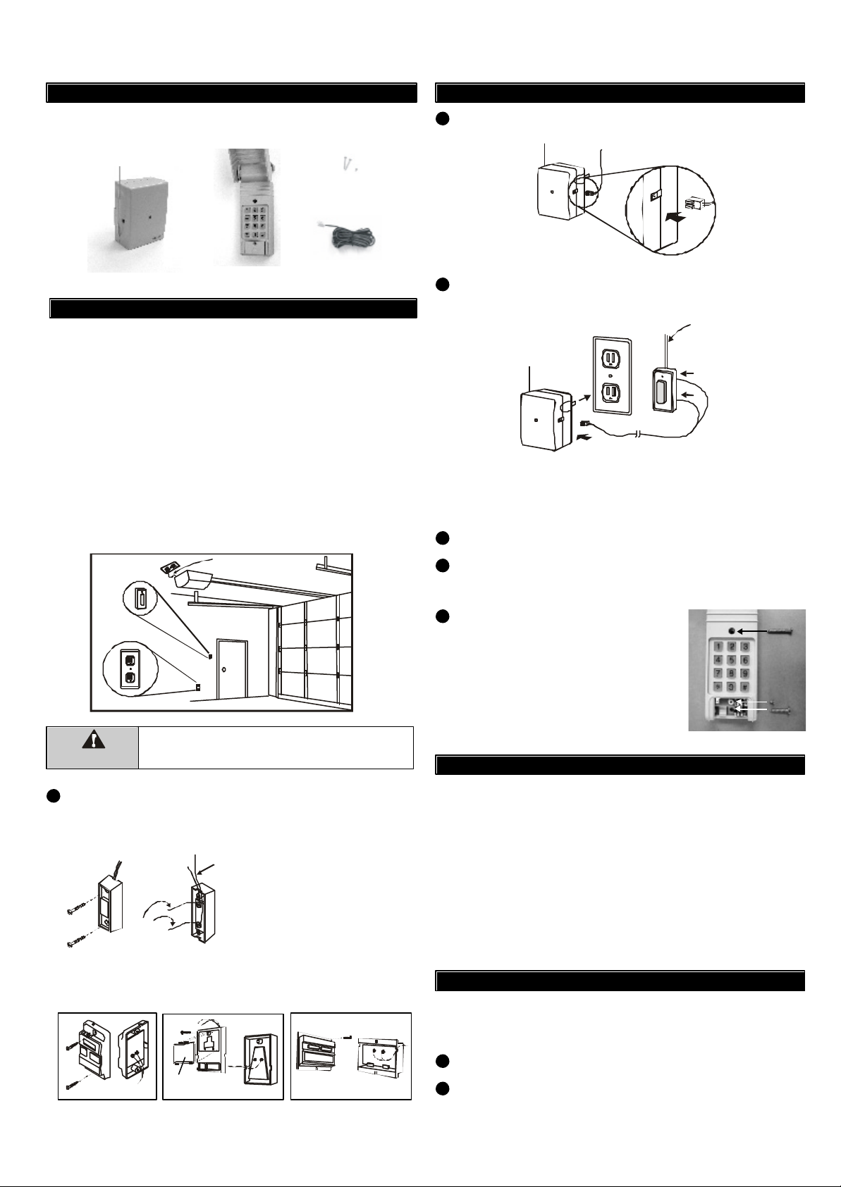
In this package, you will find a keyless entry transmitter with 3V lithium
batteries, a garage door receiver, a red / black wire and screws.
1 pc 2.6 x 6 screw (included)
1 pc 2.6 x 12 screw (included)
1 pc 2.6 x 25 screw (included)
Garage Door
Receiver
Keyless Entry Transmitter
(Batteries inside)
Red/Black Wire
2. INSTALLATION
The following instructions will show you how to install the rece iver. After
installing, the keyless entry transmitter (already programmed to the
receiver) can be used to operate your garage door opener.
You need to locate 2 things inside your garage to install the receiver:
1) the wall-mounted door control;
2) an electrical outlet, select an electrical outlet different from the one
already connected to the power cord of the garage door opener to
reduce the chance of interference. The further distance between
the receiver and the garage door opener, the less interference
between 2 devices.
Note: The length of the red/black wire is 20ft, so the receiver must be
plugged into an electrical outlet that is within 20ft of the wall mounted
door control. If there is no electrical outlet within 20ft of the wall
mounted door control, an extension cord can be used for temporary
installation.
Wall Mounted
Door Control
Electrical
Outlet
Remove power cord of garage
door opener before installation.
Plug in the connector end of the Red/Black wire to the 18R
2
receiver. Note the orientation of the male & female connector.
Plug the receiver into an electrical outlet inside the garage.
3
The red light on the receiver should be on after being plugged into an
electrical outlet.
RECEIVER
RED/BLACK WIRE
Existing wires connected
to garage door opener.
(Do not remove)
Note: Alternative wiring options are available, the receiver can be
connected directly to the opener’s motor. Please contact customer
service for further information regarding alternative wiring options.
Re-connect the power cord of the Garage Door Opener.
4
Remove the battery isolator on the transmitter and enter the factory
5
default PIN [0,0,0,0], [#], [1] you will hear 3 beeps indicating you have
entered the correct PIN. The door will now open.
You can now mount the transmitter on a
6
desired location.
Lift up the cover and insert screw
above the keypad in the slot provided (a).
Remove the battery cover and insert
the second screw in the lower slot (b).
Tighten all screws. Replace the battery
cover, insert and tighten screw (c).
(c)
(a)
(b)
Unplug the power cord of your garage door opener
WARNING
Remove the wall-mounted door control from the wall by removing
1
the screws. Connect the stripped ends of the Red/Black wire to the
before installation to ensure power is not connected.
2 terminals (2 screws) on the back of the wall mounted door
control. (Polarity does not matter.)
Existing
wires
Note: There should be another
pair of wires connected to the 2
terminals already. Do not remove/
Red /
Black wire
disconnect these existing wires.
Note: If you see no screws mounting the wall mounted door control,
the screws are probably underneath the front cover. Remove the
front cover by pressing onto the tabs on top of the cover.
Remove front
cover first
Different wall-mounted door controls
3. TROUBLE SHOOTING
Q: Door opener does not react after pressing the button on the transmitter.
A:- Ensure you hear 3 beeps from the keypad transmitter after entering
the default PIN [0,0,0,0], [#], [1]. If you do not hear 3 beeps, that means
the PIN you entered is incorrect. Re-enter the correct PIN.
- If the red light on the receiver flashes after entering the PIN on the
transmitter, but the door opener does not respond, please ensure the
red/black wire is successfully connected from the receiver to the
wall mounted door control.
- Ensure the wires that are previously connected to the wall mounted
door control are not loose.
- Ensure the keypad transmitter has been programmed to the receiver.
Refer to section 4 how to program a keypad to the receiver.
4. PROGRAM A KEYPAD TO THE RECEIVER
The transmitter in this kit has been programmed to the receiver in the
factory. You need to do the programming only when you add additional
keypad transmitter to the receiver.
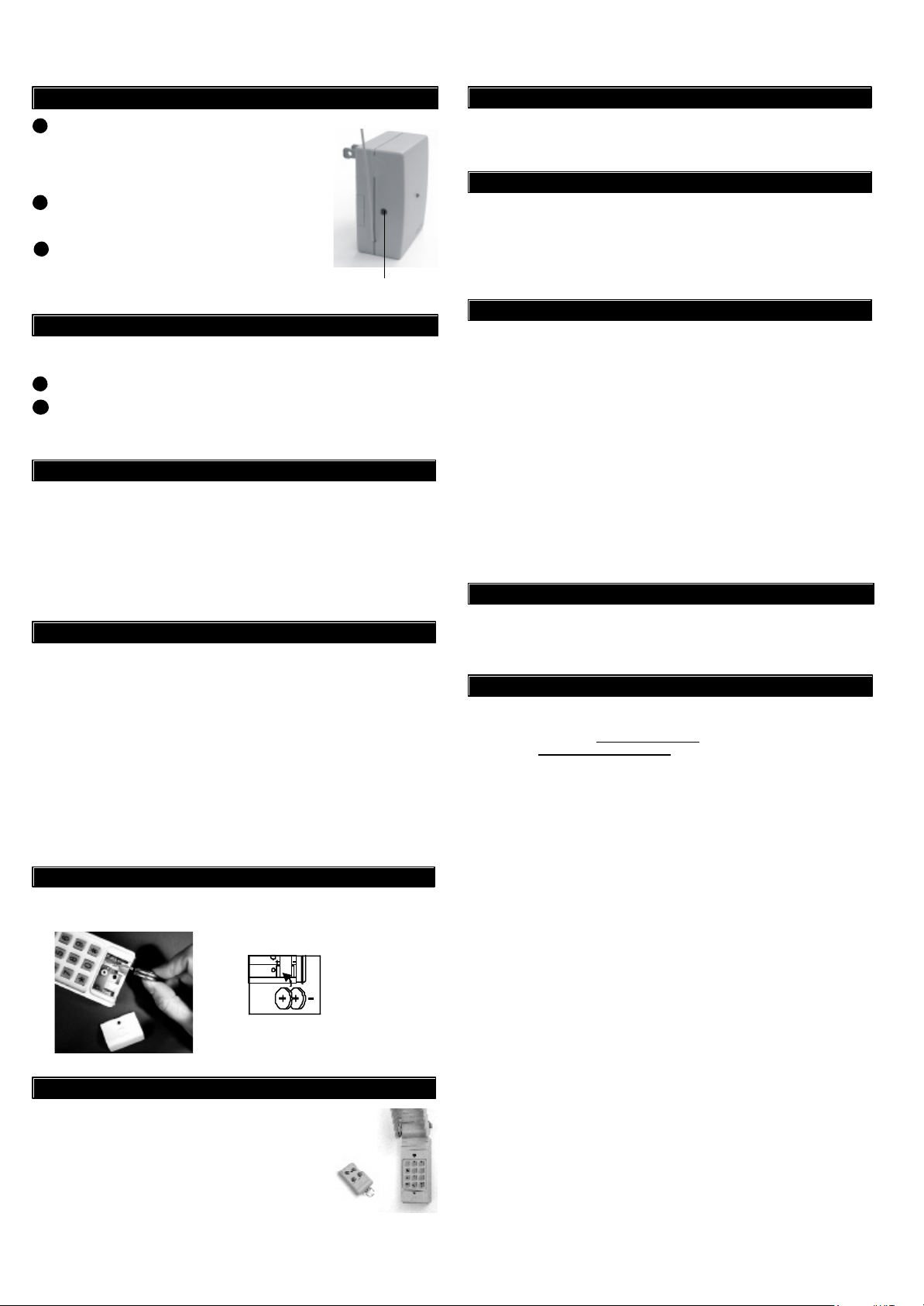
Plug the receiver into an electrical socket.
1
Press and hold the learn button at the left hand side of the receiver.
2
The red LED on the receiver will flash.
Page 2
4. PROGRAM A KEYPAD TO THE RECEIVER (CONT)
Press the [4-digit PIN], [#] and [the assigned
3
number of the door] within 5 seconds. The
assigned door number can be either 1, 2, 3 or 4.
Example: [0][0][0][0][#][3], for door 3.
The receiver red LED will go off indicates the
4
programming is completed.
To program the keypad to control more than
5
one receiver, repeat process (1) to (4) with
different assigned door numbers.
Learn Button
5. REMOVE TRANSMITTER FROM THE RECEIVER
You can delete the transmitter from a receiver.
Unplug the receiver from the electrical socket.
1
Press and hold the learn button on the left hand side of the receiver
2
when plugging the receiver into an electrical socket, the red LED on the
receiver will flash rapidly. All the transmitters and keypads are deleted.
6. KEYPAD OPERATION
The backlight comes on and a beep is emitted when any key is pressed.
The backlight of the keypad may not be visible when it is too bright
outside. When any key is pressed, the next key must be pressed w ithin 5
seconds or the backlight turns off and the sequence is cancelled. You
must begin again.
If the keypad does not emit a beep when pressed, wait a few seconds
and press the key again.
7. CHANGE PIN
Follow the instructions below to change the PIN.
To change your PIN:
1. Enter the current PIN, (factory default PIN 0 0 0 0), press ,
2. Enter new 4 to 6 digit PIN, press ,
3. Enter new PIN again, press .
*
*
*
For example, if you are changing the PIN number from 0000 to
123456, enter the following sequence, 0000, ,123456, ,123456, .
*
**
If confirmed, the backlit LED flashes and the unit emits a long beep.
10. ADDITIONAL RECEIVER
You can use 18K to control up to 4 garage door openers by adding
Skylink® Garage Door Receiver 18R for each opener.
1 1. CAUTION
RISK OF ELECTRICAL SHOCK. FOR INDOOR USE ONLY.
CAUTION : DISCONNECT POWER BEFORE SERVICING.
Maximum Rating:
Input : 120VAC 60Hz 2W
12. FCC
This device complies with Part 15 of the FCC Rules. Operation is subject to the following two conditions:
(1) This device may not cause harmful interference, and (2) This device must accept any interference
received, including interference that may cause undesired operation.
WARNING:
Changes or modifications to this unit not expressly approved by the party responsible for compliance could
void the user’s authority to operate the equipment.
NOTE:
This equipment has been tested and found to comply with the limits for a Class B digital device, pursuant
to Part 15 of the FCC Rules. These limits are designed to provide reasonable protection against harmful
interference in a residential installation. This equipment generates, uses and can radiate radio frequency
energy and, if not installed and used in accordance with the instructions, may cause harmful interference
to radio communications.
However, there is no guarantee that interference will not occur in a particular installation. If this equipment does
cause harmful interference to radio or television reception, which can be determined by turning the equipment
off and on, the user is encouraged to try to correct the interference by one or more of the following measures:
- Reorient or relocate the receiving antenna.
- Increase the separation between the equipment and receiver.
- Connect the equipment into an outlet on a circuit different from that to which the receiver is connected.
- Consult the dealer or an experienced radio/TV technician for help.
13. WARRANTY
If, within one year from date of purchase, this product should become defective
(except battery), due to faulty workmanship or materials, it will be repaired or
replaced, without charge. Proof of purchase and a Return Authorization are required.
14. CUSTOMER SERVICE
If you would like to order Skylink’s products or have difficulty getting them to work,
please :
1. visit our FAQ web site at www.skylinkhome.com, or
2. email us at support@skylinkhome.com , or
3. call our toll free at 1-800-304-1187 from Monday to Friday, 9 am to 5 pm EST.
Fax +800 286-1320
If you do not hear 3 beeps after the 4-digit PIN, [#] and [assigned door
number] is entered, that means you have entered an incorrect PIN, and
the keypad transmitter will not operate your garage door.
8. BATTERY
Two 3 volt Lithium type (CR2032) batteries (included).
-
It is time to change
the batteries when
+
Battery Compartment
the backlight no
longer appears.
9. ADDITIONAL TRANSMITTER
You can add up to 15 transmitters as you want to
control the same receiver. Simply program the
transmitters to the receiver. Skylink® offers Keychain
Transmitter Model 18T4 and Keyless Entry Transmitter
Model 18K to work with your receiver.
For more information, please visit our website at
www.skylinkhome.com or contact us.
CUSTOMER SERVICE
17 Sheard Avenue, Brampton, Ontario, Canada L6Y 1J3
Email:support@skylinkhome.com
http://www.skylinkhome.com
P/N. 101A288-001 Rev.1
©2004 SKYLINK GROUP
 Loading...