

Page 1
Skybox Appliance 6000
Quick Start Guide
9.0.400
Revision: 11
Page 2

Proprietary and Confidential to Skybox Security. © 2018 Skybox Security,
Inc. All rights reserved.
Due to continued product development, the information contained in this
document may change without notice. The information and intellectual property
contained herein are confidential and remain the exclusive intellectual property of
Skybox Security. If you find any problems in the documentation, please report
them to us in writing. Skybox Security does not warrant that this document is
error-free.
No part of this publication may be reproduced, stored in a retrieval system, or
transmitted in any form or by any means—electronic, mechanical, photocopying,
recording, or otherwise—without the prior written permission of Skybox Security.
®
Skybox
, Skybox® Security, Skybox Firewall Assurance, Skybox Network
Assurance, Skybox Vulnerability Control, Skybox Threat Manager, Skybox
Change Manager, Skybox Appliance 5500/6000/7000/8000/8050, and the
Skybox Security logo are either registered trademarks or trademarks of Skybox
Security, Inc., in the United States and/or other countries. All other trademarks
are the property of their respective owners.
Contact information
Contact Skybox using the form on our website
or by emailing
Customers and partners can contact Skybox technical support via the Skybox
Support portal
Page 3

Contents
Overview ............................................................................................... 5
Basic architecture ..................................................................................... 5
Related documentation .............................................................................. 5
Skybox Appliance specifications ................................................................ 6
Before you open the b ox ........................................................................... 6
What’s in the box ..................................................................................... 6
Physical specifications ............................................................................... 7
Environmental specifications ...................................................................... 7
MTBF estimates for Skybox Appliance ......................................................... 9
Front panel .............................................................................................. 9
Back panel connectors ............................................................................. 11
Port mapping .................................................................................... 11
File system partitions .............................................................................. 11
Setting up Skybox Appliance ................................................................... 12
Installation ............................................................................................ 12
Starting Skybox Appliance .................................................................. 12
System configuration .............................................................................. 13
Configuring connection ....................................................................... 13
Setting up the Appliance for configuration ............................................ 18
First-time configuration ...................................................................... 18
What’s next ........................................................................................... 18
Configuring the Appliance ....................................................................... 20
Configuration and management options ..................................................... 20
Setting up network interface bonding ........................................................ 22
Supported bond modes ...................................................................... 22
Setting up SNMP configuration ................................................................. 24
RADIUS authentication ............................................................................ 24
LDAP authentication ................................................................................ 25
Changing the TLS version ........................................................................ 27
Customizing the syslog server ................................................................. 29
TCP and UDP listeners ............................................................................. 29
How to work with syslog files ................................................................... 29
Skybox Manager Installation .................................................................... 31
Manager system requirements ................................................................. 31
Skybox version 9.0.400 3
Page 4

Skybox Appliance 6000 Quick Start Guide
Installing Skybox Manager ....................................................................... 32
Upgrading the Manager ........................................................................... 32
Updating the operating system on Skybox Appliance .................................. 33
Adding a customer certif icate .................................................................. 35
Restoring the Appliance to factory defaults ................................................ 36
Monitoring SNMP .................................................................................... 37
Troubleshooting ..................................................................................... 39
Wiping the hard disk drive ....................................................................... 40
Regulatory and safety information ............................................................ 41
Product regulatory compliance ................................................................. 41
Safety compliance ............................................................................. 41
EMC compliance – Class A compliance .................................................. 42
Environmental requirements ............................................................... 42
Product regulatory compliance markings .................................................... 42
Electromagnetic compatibility notices for the server board ........................... 45
Skybox version 9.0.400 4
Page 5

Related documentation .......................................................... 5
Overview
Chapter 1
Skybox® Appliance is a hardware solution that enables you to deploy Skybox
easily, without the burden of maintaining your own server.
®
Skybox
that helps enterprise IT departments to discover and resolve potential security
and compliance risks before they impact your organization.
Skybox is a multi-tier platform. Skybox Appliance runs the Server and users run
Managers (clients) that connect to the Server over the network. Skybox also
runs an additional Skybox component, the Collector, which connects to data
sources and imports the data to the Server.
The Skybox Server and Collector are preinstalled on Skybox Appliance and run at
startup.
is an Automated Risk and Compliance Management (ARCM) platform
In this chapter
Basic architecture ................................................................. 5
Basic architecture
The Skybox platform consists of a 3-tiered architecture with a centralized server
(Skybox Server), data collectors (Skybox Collectors), and a user interface
(Skybox Manager). Skybox can be scaled easily to suit the complexity and size of
any infrastructure.
For additional information, see the Skybox architecture topic in the Skybox
Installation and Administration Guide.
Related documentation
Related documentation includes:
› Skybox online help
› Skybox documentation
Skybox version 9.0.400 5
Page 6

File system partitions .......................................................... 11
•
•
Skybox Appliance specifications
Chapter 2
This chapter contains product specifications and packaging information for
Skybox Appliance 6000.
In this chapter
Before you open the box ........................................................ 6
What’s in the box .................................................................. 6
Physical specifications ........................................................... 7
Environmental specifications .................................................. 7
MTBF estimates for Skybox Appliance ...................................... 9
Front panel .......................................................................... 9
Back panel connectors ......................................................... 11
Before you open the box
Inspect the shipping carton to ensure that the packaging has not been damaged
and verify that all tamper evident seals are intact. Verify that the Appliance serial
number, purchase order number, and FedEx tracking number match the
information provided by Skybox Customer Support.
What’s in the box
The following items are included in the shipping carton:
› Skybox Appliance
› Rack mount kit
› Front bezel
› 2 AC power cords
› RJ45 to DB9 serial console cable
› Skybox Quick Start Guide
› 2 DVDs
Skybox: Installs Skybox on the Skybox Appliance; it contains the Skybox
software and additional Appliance documentation
Restore Appliance: Restores the Skybox Appliance to factory settings
Skybox version 9.0.400 6
Page 7

Chapter 2 Skybox Appliance specifications
• System weight: 31.8 lb (14.42 kg)
• Packaged weight: 42.4 lb (19.23 kg)
6 dual rotor managed system fans
• 2 power supply fans
• 1 power button with integrate d LED
• Bezel with lock support
• DB-15 video connectors
5 network interface (LAN) connectors supporting
Physical specifications
The physical features of Skybox are listed in the following table.
Feature Description
Form factor 1U rack
Rack dimensions
(H x W x D)
Weight
Power supply 750 W redundant AC
Data storage RAID 5
System cooling
Front panel
features
External I/O
connectors
(back panel)
1.70” x 17.24” x 27.93” (43.2mm x 438 mm x 709.37
mm)
•
• 1 system ID button with integrated LED
• 1 system status LED
• 4 NIC LEDs
• 1 HDD activity LED
• 1 system cold reset button
• 2 USB 2.0 connectors
• 1 video connector
• RJ45 serial port A connector
• 3 USB 2.0 Ports
• 4 RJ-4
10/100/1000 Mb
Note: Ports I/O and RMM4 are not supported.
Compliant
standards
Ctick, NRTL, CE, FCC, EMC, BSMI, KC, and more
For detailed information, see Regulatory and safety
information (on page 41).
Environm ent a l sp ec if ic a tions
Environmental specifications for Skybox are listed in the following table.
Property Limits
Operating
temperature
Non-operating
temperature
Non-operating
humidity
Acoustic noise Sound pressure: 55 dBA (rack mount) in an idle state at
+10°C to +35°C with the maximum rate of change not to
exceed 10°C per hour
-40°C to +70°C
90%, non-condensing at 35°C
typical office ambient temperature . (23 +/- 2 degrees C)
Sound power: 7.0 dBA in operating conditions at typical
office ambient temperature. (23 +/- 2 degrees C)
Skybox version 9.0.400 7
Page 8

Skybox Appliance 6000 Quick Start Guide
≧
Property Limits
Shock, operating Half sine, 2 g peak, 11 msec
Shock,
unpackaged
Shock, packaged Non-palletized free fall height: 24 inches (≧40 lbs to <80
Vibration,
unpackaged
ESD +/-12 KV except I/O port +/- 8 KV per Intel®
System cooling
requirement
EMI operating Required to meet EMI emission requirements, tested as
Trapezoidal, 25 g, velocity change 136 inches/second
40 lbs to <80 lbs)
(
lbs)
5 Hz to 500 Hz, 2.20 g RMS random
Envir onmental test specification
2027.7 BTU/hour
part of system
Skybox version 9.0.400 8
Page 9
Chapter 2 Skybox Appliance specifications
MTBF estimates for Skybox Appliance
The estimated mean time between failures (MTBF) and Failures in Time (FIT) for
Skybox Appliance 6000 are listed in the following table.
Subassembly MTBF (hours) FIT (failures/10^9
hours)
Intel® Server Board S2600GZ 196253 5095
Backplane board 935189 1069
750W redundant power supplies
806081 1241
(1+1)
Cooling fans 83131 12029
PCI Riser card 7303481 137
Front panel board 8272282 121
Dedicated NIC module 2869529 348
Total FIT rate
20178
System MTBF hrs @ 40°C 49560
System MTBF hrs @ 35°C 63214
System MTBF hrs @ 25°C 82325
Note: The estimates listed here are for Appliance in 35°C ambient air with a rise
of up to 10°C at the Server Board.
Front panel
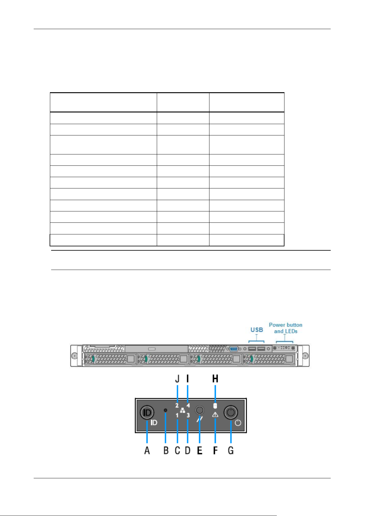
Skybox Appliance 6000’s front panel includes 2 USB connectors, plus a power
button and LEDs.
Skybox version 9.0.400 9
Page 10

Skybox Appliance 6000 Quick Start Guide
Power button and LEDs
Letter Feature
A System ID button with integrated LED
B NMI button (recessed; tool required f or use)
C NIC1 activity LED
D NIC3 activity LED
E System cold reset button
F System status LED
G Power button with integrated LED
H Hard drive activity LED
I NIC4 activity LED
J NIC2 activity LED
Front panel LED functions
LED Color/State Description
Power/Sleep
NIC LEDs
System Status
Green/on Power on
Green/blinking Sleep
Off Power off
Green/on Network link but no network activity
Green/blinking Network activity
Off No link
Green/on System ready/no alarm
Green/blinking System ready but degraded:
Redundancy lost (for example, a
power supply or fan failure);
non-critical temperature or voltage
threshold reached; battery failure; or
predictive power supply failure.
Amber/on Critical Alarm: Critical power modules
failure, critical fans failure, voltage
(power supply), critical temperature
and voltage
Amber/blinking Non-Critical Alarm: Redundant fan
failure, redundant power module
failure, non-critical temperature and
voltage
Off Power off: System unplugged
Power on: System powered off and in
standby, no prior
degraded/non-critical/critical state
Skybox version 9.0.400 10
Page 11
Chapter 2 Skybox Appliance specifications
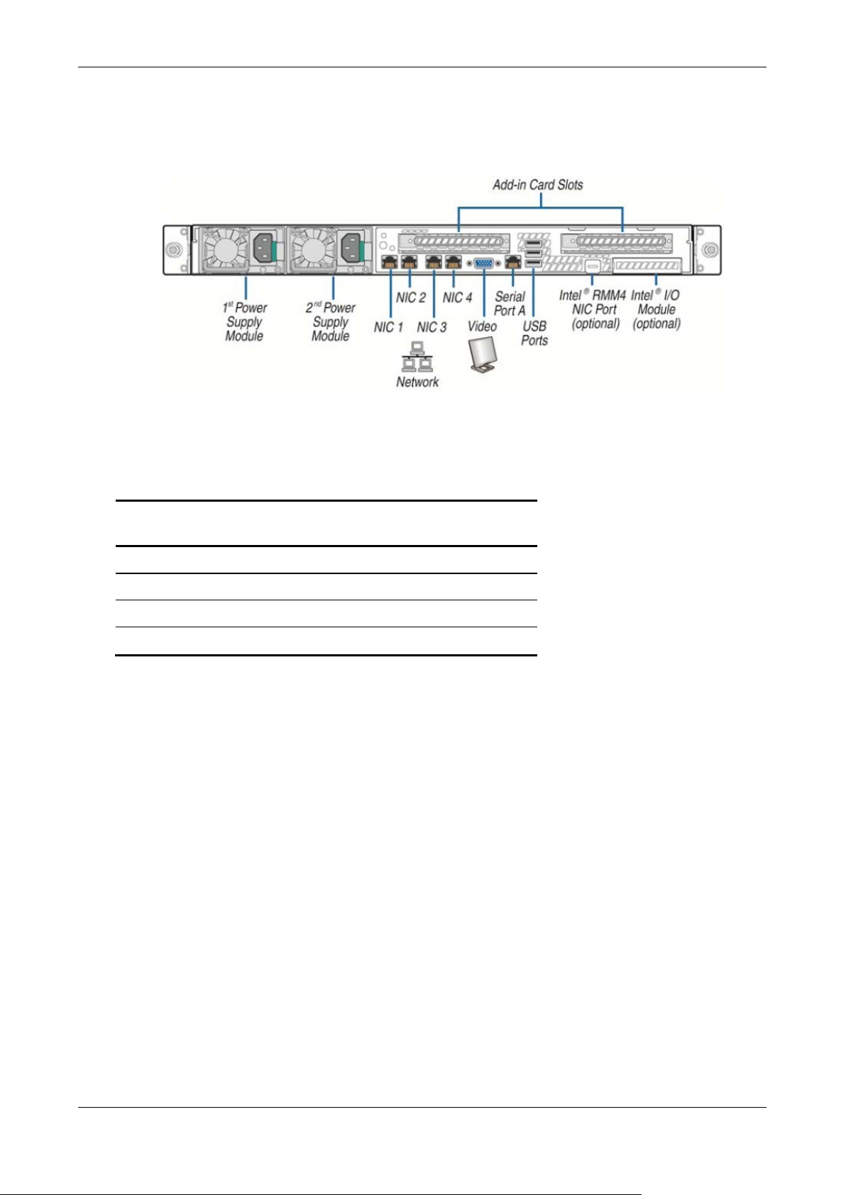
Back panel connectors
Skybox Appliance 6000’s back panel includes the connectors shown in the
following figure.
PORT MAPPING
The mappings between physical ports on the back panel of Skybox Appliance and
logical ports are listed in the following table.
Back panel
connector
NIC1 eno1
NIC2 eno2
NIC3 eno3
NIC4 eno4
By default:
Logical port to which it is
mapped
› NIC1 / eno1 is enabled and configured as DHCP
› NIC2 / eno2 is enabled and configured as static with the IP address:
192.168.1.1 /24
You can change these values.
File system pa rtitions
Skybox Appliance’s file system is partitioned as follows:
› SWAP: 4 GB
› /tmp: 5% of the entire space
› /: 20% of the entir e spac e
› /var: 45% of the entire space
› /opt: The rest of the disk
Skybox version 9.0.400 11
Page 12

What’s next ........................................................................ 18
Setting up Skybox Appliance
Chapter 3
This chapter explains how to set up Skybox Appliance.
In this chapter
Installation ........................................................................ 12
System configuration .......................................................... 13
Installation
Before installation
Before installing the rack mount kit, observe these safety guidelines:
1 Turn off all peripheral devices connected to Skybox Appliance.
2 Turn off Skybox Appliance by pressing the Power button on the front of the
chassis, and then unplug the AC power cords from the chassis or wall outlet.
3 Label and disconnect all peripheral cables and all telecommunications lines
connected to I/O connectors or ports on the back of the chassis.
4 Provide electrostatic discharge (ESD) protection by wearing an antistatic wrist
strap attached to a chassis ground—any unpainted metal surface—when
handling components.
Required tools and supplies
› Phillips (cross head) screwdriver (#1 bit and #2 bit)
› (Recommended) Antistatic wrist strap and conductive foam pad
Installation
To install Skybox, refer to the installation instructions included with the rack
mount kit.
STARTING SKYBOX APPLIANCE
To start the Appliance
1 Connect the AC power cords to the AC connectors on Skybox’s back panel and
connect the other ends to a power supply.
Note: You can use Skybox with either a 110 or 220 volt power supply.
Skybox version 9.0.400 12
Page 13

Chapter 3 Setting up Skybox Appliance
2 On the Appliance’s front panel, press the Power button.
3 Lock the front bezel in place using the key provided.
System configuration
Before running the Skybox Server, configure Skybox Appliance to be part of your
network and perform initial system configuration.
CONFIGURING CONNECTION
Before using the Skybox Appliance Administration, you must configure
connection of Skybox to your network locally, using any of:
› The RMM interface on the Appliance
› A console (mouse, ke y board, and screen) connection
› A serial port connection
› A network connection via static NIC
Note: For a figur e of the connectors used in t h e following procedures, see Back
panel connectors (on page 11).
Configuration via the RMM interface
You can connect to the Appliance via its RMM interface by connecting a network
cable to the RMM port.
The RMM interface is preconfigured with the DHCP server. However, you must
configure Java to work with the RMM.
Configuring Java to work with the RMM
This procedure configures Java security on your computer to recognize the RMM
of the Appliance machine. This enables you to log in to the RMM of the Appliance
machine from your c omputer.
Skybox version 9.0.400 13
Page 14
Skybox Appliance 6000 Quick Start Guide
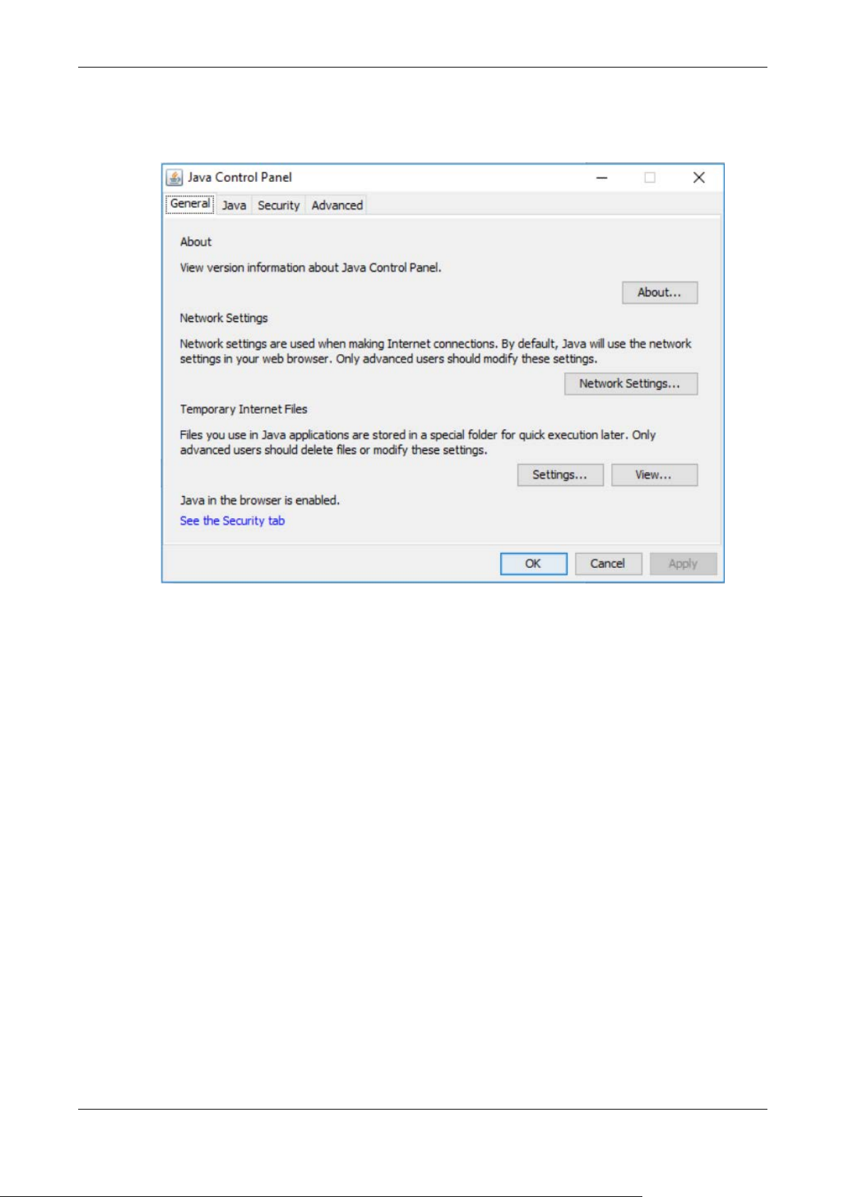
To configure Java security on your Windows machin e to work with the
RMM
1 From the Windows Start menu, select Configure Ja va.
Skybox version 9.0.400 14
Page 15
Chapter 3 Setting up Skybox Appliance
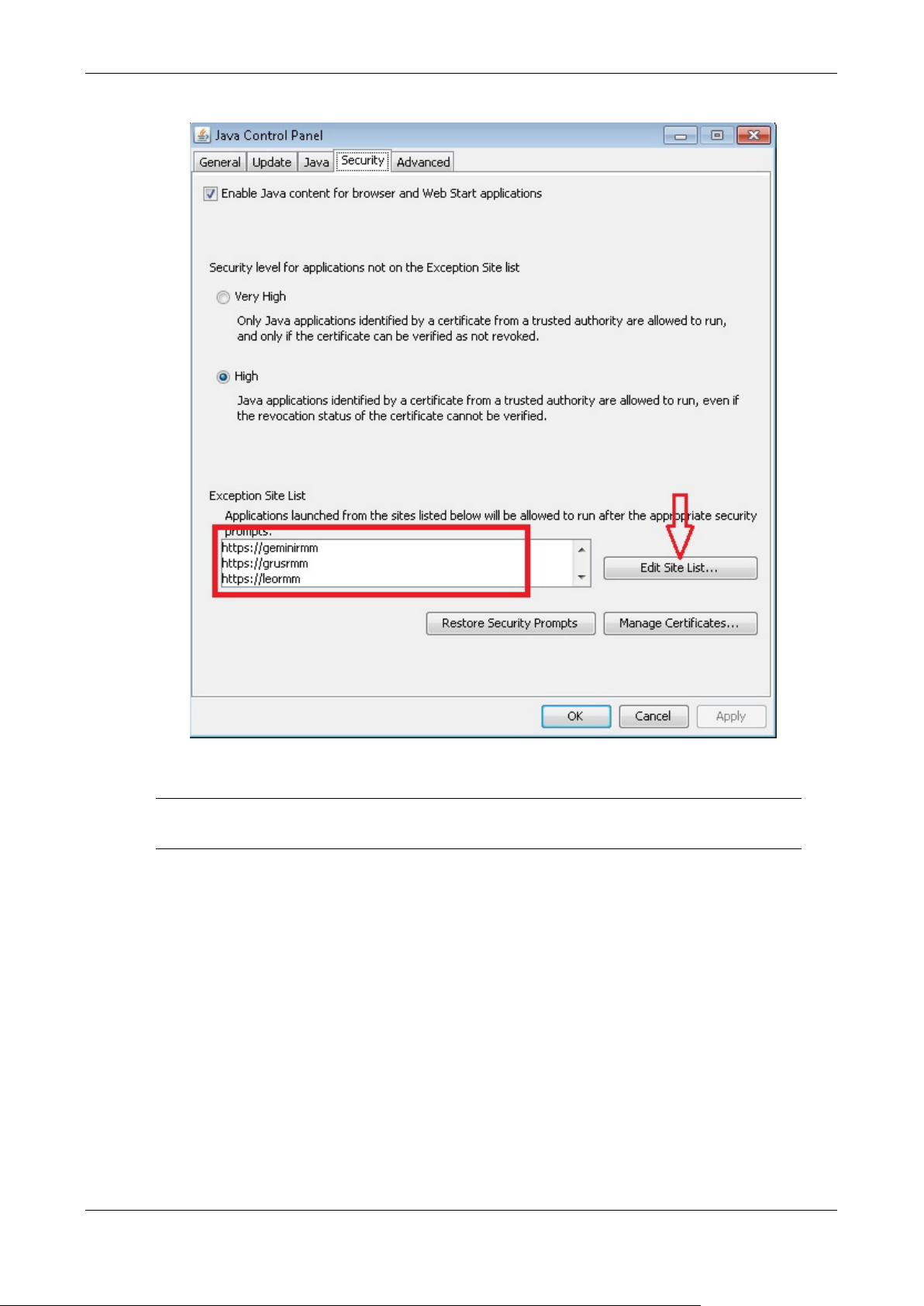
2 In the Java Control Panel dialog box, click the Security tab.
3 In the Exception Site List field, add the URL for the RMM of the Appliance
machine.
Note: If you do not know the URL of the RMM, you can r u n t he following
command as root user on the Appliance machine: ipmitool lan print 1
Configuring the RMM administrator
You must change the administrator password on the RMM.
To change the RMM administrator password
1 Reboot the Appliance.
2 During the boot process, press F2 to open the BIOS setup.
3 From the menu, select Server Management.
4 Select BMC LAN configuration.
5 Select User Configuration to configure the RMM user.
On the User Configuration page:
a. Click User ID and select an unused user ID to be the RMM user.
b. Configure the user:
Skybox version 9.0.400 15
Page 16

Skybox Appliance 6000 Quick Start Guide
•
•
— Privilege: Select Administrator.
— User Status: Select Enabled.
— User Name : Ty pe the desired na me. (Note: The name of the
anonymous user cannot be changed.)
— User Password: Type the desired password twice.
6 When you are finished, press F10 to save and exit the configuration.
The Appliance boots with the RMM interface configured with the user that you
provided.
Troubleshooting the RMM IP address
To change the IP address of the RMM
1 Reboot the Appliance.
2 During the boot process, press F2 to open the BIOS setup.
3 From the menu, select Server Management.
4 Select BMC LAN configuration.
When using DHCP: The system assigns the host name of the RMM and the
IP address.
Note that you can configure the host name at the bottom of the page, in
the BMC hostname field.
When using a Static address: Provide the IP address, netmask, and
gateway IP address.
5 When you are finished, press F10 to save and exit the configuration.
The Appliance boots with the RMM interface configured with the user that you
provided.
Configuration via console
To configure connection using a mouse, keyboard, and screen
1 Connect one end of a standard network cable to the NIC 1 (eno1) port on the
Appliance’s back panel; connect the other end of the cable to a network
socket.
2 Connect a mouse, keyboard, and screen to the connectors on the Appliance’s
back panel.
3 Log in to the Appliance using the default user name (root) and the default
password (skyboxview).
4 Run the command: set_appliance_network
This command configures network interfaces with an IP address, netmask,
and default gateway.
a. Select a network interface to configure.
b. Select the IP mode (static or DHCP).
— When using static mode, you must provide the IP address, netmask,
and default gateway.
Skybox version 9.0.400 16
Page 17

Chapter 3 Setting up Skybox Appliance
•
•
•
•
•
•
5 If you are using DHCP, run ifconfig, and write down the IP address
assigned to the Appliance. You will need it later.
Configuration via serial port
To configure connection using a serial port connection
1 Connect one end of the serial cable to a serial port on the management
computer; connect the other end to the serial port on the Appliance.
2 On the management computer start a terminal emulation program, select the
port that you connected to in the previous step, and configure the following
port settings:
Bits per second: 9600
Data bits: 8
Parity: none
Stop bits: 1
Flow control: non e
(If using PuTTY as your terminal emulator) Character set translation on
received data: UTF-8
3 Press the Power button on the Appliance’s front panel and verify that the
Power LED turns green.
4 Log in to the Appliance using the default user name (root) and the default
password (skyboxview).
5 Run the command: set_appliance_network
This command configures network interfaces with an IP address, netmask,
and default gateway.
a. Select a network interface to configure.
b. Select the IP mode (static or DHCP).
— When using static mode, you must provide the IP address, netmask,
and default gateway.
6 If you are using DHCP, run ifconfig, and write down the IP address
assigned to the Appliance. You will need it later.
Configuration via network port
You can connect to the Appliance via the preconfigured static network port
(eno2), whose IP address is 192.168.1.1 /24.
To configure connection via eno2
1 Configure the IP of the client side to a different IP address on the same
network. For example, 192.168.1.50 /24.
2 In your browser, connect via the IP address for eno2:
https://192.168.1.1:444/
Skybox version 9.0.400 17
Page 18

Skybox Appliance 6000 Quick Start Guide
•
SETTING UP THE APPLIANCE FOR CONFIGURATION
To prepare for configuring the system remotely
1 From a different machine on the network, open a browser to connect to the
Skybox Appliance Administration using the following URL, where <appliance
IP address> is the IP address of the Appliance that you configured in
Configuring connection (on page 13):
https://<appliance IP address>:444
2 The default user name is skyboxview; the default password is skyboxview.
The Skybox Appliance Administration main page appears.
FIRST-TIME CONFIGURATION
You must change the passwords and configure the date and time before using
the Skybox Server. All other settings are optional; you can configure them later.
To change the passwords
1 On the Security tab, select Appliance Passwords.
2 To change the root password of the machine, click Change Root Password.
3 To change the Appliance Administration password, click Change Skyboxview
Password.
To configure the date and time
1 On the System tab, select Date and Time Configuration.
2 To configure date and time manually:
a. Select Manual Date and Time Configuration.
b. Click Change Date and Time; set the date and time for Skybox’s time
zone.
c. Click Change Time Zone; set the time zone for th e location where the
Appliance is installed, so that reports and other data are timestamped
correctly.
3 To set date and time from a time server:
a. Select Automatic Date and Time Configuration Using NTP Server.
b. Click Change NTP Se rv er; add the IP address or DNS of the time server
to use.
c. Click Change Time Zone; set the time zone for th e location where the
Appliance is installed, so that reports and other data are timestamped
correctly.
What’s next
Skybox Manager is the client application that communicates with the Server.
After installing and configuring the Appliance, you must install the Manager on at
least 1 remote machi ne (see Skybox Manager Installation (on page 31)).
Skybox version 9.0.400 18
Page 19

Chapter 3 Setting up Skybox Appliance
Using Skybox for change tracking
You can use Skybox to track changes on firewalls. Although much change
information can be collected directly from the firewalls, additional information
(including a timestamp and the user who made the change) is available only
from syslog change events that are sent to the syslog server in the Appliance.
You collect the change events using Change Tracking Events – Syslog Import
tasks.
Syslog server
The syslog server in the Appliance is preconfigured and is enabled by default.
Updates to the configuration files of the syslog server and syslog log file rotation
are included (when necessary) as part of Skybox updates.
For information about customizing the syslog server, see Customizing the syslog
server (on page 29).
Skybox version 9.0.400 19
Page 20

Changing the TLS version ..................................................... 27
Configuration
Configuring the Appliance
Chapter 4
The following sections explain how to configure the Appliance.
› Configuration and management options (Appliance Administration) (on page
20)
› Setting up SNMP configuration (on page 24)
› RADIUS authentication (on page 24)
› LDAP authentication (on page 25)
› Changing the TLS version (on page 27)
In this chapter
Configuration and management options ................................. 20
Setting up network interface bonding..................................... 22
Setting up SNMP configuration .............................................. 24
RADIUS authentication ......................................................... 24
LDAP authentication ............................................................ 25
Configuration and management options
Skybox Appliance’s configuration options are described in the following table.
Pane Description
About tab
System
Information
Network tab
Note that changes to the configuration infor m a tion ma d e in this tab are
only saved after you click Save Network Configuration.
Provides information about Skybox configuration.
Network
Configuration
Network
Skybox version 9.0.400 20
Enables you to configure network settings (connection
method, IP address, netmask, and gateway) and
bonding for each network interface connection, and to
configure the DNS servers.
Note: For non-virtual Appliances, this pane includes a
link to a figure of the back panel to help you to
understand the connections.
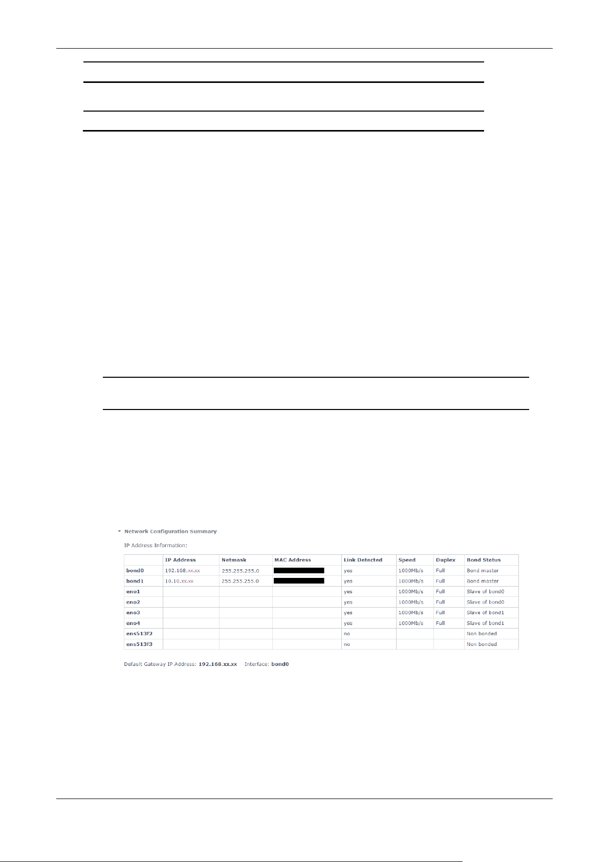
Displays a summary of the Appliance conf iguration
Page 21

Chapter 4 Configuring the Appliance
Summary
information.
Automatic configuration synchronizes Skybox with an
Set the time zone after setting the NTP server.
Get Packlogs: Runs the packlogs utility and saves the
Pane Description
Click Export to save this information to an HTML file .
System tab
Date and Time
Configuration
Enables you to view and change the date and time in
the Appliance’s time zone.
Notes:
• When setting this information manually, set the date
and time and then the time zone for the location
where the Appliance is installed, so that reports and
other data are timestamped correctly.
•
atomic clock. You must provide the IP address or
DNS of the NTP server to use.
Syslog Server Starts or stops the syslog server service and enables
you to configure TCP and UDP listeners (see
Customizing the syslog server (on page 29)).
Host Name Enables you to change the name of the Appliance.
Change System
Mode
Toggles between Server mode (where the Appliance
functions as both Server and a Collector ) and Collector
mode (where the Appliance functions only as a
Collector).
SNMP Select Enable SNMP Service to set up SNMP
configuration, host configuration, and sending traps
(see Setting up SNMP configuration (on page 24)).
You can also downloa d the A ppliance MIBs.
Security tab
Appliance
Passwords
Enables you to change the root password for the
Appliance and the password for the Appliance
Administration.
LDAP Enables you to set up the Appliance to support
authentication via LDAP (see LDAP authentication). (on
page 25)
SSH Toggles the SSH service on and off and enables the roo t
user to log in via SSH.
Control tab
Skybox Services Toggles the Server and Collector on and off.
Note: Turning a Skybox service off stops the service
and switches it to Manual mode. Turning the service on
restarts the service and switches it back to Automatic
mode.
Appliance
Enables you to reboot or shut down the Appliance .
Operations
Support tab
Logs Enables you to view Server, Collector, and other logs of
the Appliance.
Skybox version 9.0.400 21
Page 22
Skybox Appliance 6000 Quick Start Guide
packlogs (ZIP) file to a local directory so that you can
Pane Description
send the logs to Skybox Support.
Skybox Manager Enables you to download the Manager for installation.
Setting up network interface bonding
Skybox Appliances support network interface bonding for redundancy and for
higher bandwidth.
To create a network interface bonding
1 On the Network tab, click Network Configuration.
2 Select Network Interfaces.
3 Select an interface that you want to add to a network bond and click Add to
Network Bond.
4 In the Network Bond Setup dialog box, add a new bond interface.
5 Select the interfaces to bond to this new interface (as slaves).
6 Select the method for assigning the IP address for this interface.
When using static mode, you must provide the IP address, netmask, and
gateway.
7 Select the mode in which the bond is to work; we recommend active-backup.
For information about the supported bond modes, see below.
8 Click Save.
To view a list of the network interface bonding
› On the Network tab, click Network Configuration Summary.
SUPPORTED BOND MODES
This section lists supported bond modes. We recommend active-backup for
Skybox clusters.
mode=0 (balance-rr)
Round-robin policy: Transmit packets in sequential order from the 1st available
slave to the last. This mode provides load balancing and fault tolerance.
Skybox version 9.0.400 22
Page 23

Chapter 4 Configuring the Appliance
mode=1 (active-backup)
Active-backup policy: Only a single slave in the bond is active. A different slave
becomes active if, and only if, the active slave fails. The bond’s MAC address is
externally visible on a single port (network adapter) to avoid confusing the
switch. This mode provides fault tolerance. The primary option affects the
behavior of the mode.
mode=2 (balance-xor)
XOR policy: Transmit based on [(source MAC address XORed with destination
MAC address) modulo slave count]. This selects the same slave for each
destination MAC address. This mode provides load balancing and fault tolerance.
mode=3 (broadcast)
Broadcast policy: transmits everything on all slave interfaces. This mode
provides fault tolerance.
mode=4 (802.3ad)
IEEE 802.3ad Dynamic link aggregation. Creates aggregation groups that share
the same speed and duplex settings. Utilizes all slaves in the active aggregator
according to the 802.3ad specification.
Prerequisites:
› ethtool support in the base drivers for retrieving the speed and duplex of each
slave.
› A switch that supports IEEE 802.3ad Dynamic link aggregation. Most switches
require configuration to enable 802.3ad mod e.
mode=5 (balance-tlb)
Adaptive transmit load balancing: channel bonding that does not require any
special switch support. The outgoing traffic is distributed according to the load
(computed relative to the speed) on each slave. Incoming traffic is received by
the current slave. If the receiving slave fails, another slave takes over the MAC
address of the failed receiving slave.
Prerequisite:
› ethtool support in the base drivers for retrieving the speed of each slave.
mode=6 (balance-alb)
Adaptive load balancing: includes transmit load balancing and receive load
balancing for IPV4 traffic, and does not require any special switch support. The
receive load balancing is achieved by ARP negotiation. The bonding driver
intercepts the ARP replies sent by the local system on their way out and
overwrites the source hardware address with the unique hardware address of a
slave in the bond such that different peers use different hardware addresses for
the server.
Skybox version 9.0.400 23
Page 24
Skybox Appliance 6000 Quick Start Guide
•
•
•
Setting up SNMP configuration
To use the Appliance as an SNMP Server
1 On the System tab, click SNMP.
2 Select Enable SNMP Service.
3 Set the following v alues:
On the General tab:
— System Locati o n: Phy si cal location of the Appliance
— Contact Details: Email address of the administrator
On the Security tab:
— Read Only Community: SNMPv1 or SNMPv2 community string
— Source: Name or IP address and subnet, represented as IP/netmask
(10.10.10.0/255.255.255.0) or IP/bits (10.10.10.0/24).
Multiple sources must be comma-separated
On the Notification (Traps) tab:
— Destination: Name or IP address of the notification receiver traps
server
— Traps Community: SNMP community of the notification receiver traps
server
4 When you are finished, click Save SNMP Configuration to save the
configuration and update the service with the new configuration.
RADIUS aut hentication
This topic explains how to configure RADIUS authentication for Skybox Appliance.
Note: To use RADIUS authenti cati on, the pam_radius package must be installed
on the Skybox Server. You can check whether it is installed using the rpm
–qa|grep pam_radius command. If you need help installing the package, contact
Skybox Support.
To configure RADIUS authentication
1 Open /etc/pam.d/system-auth in your editor and find the following line:
auth sufficient pam_unix.so nullok try_first_pass
2 Add the following line immediately after it:
auth sufficient pam_radius_auth.so
3 Save and close the file.
4 Open /etc/pam.d/password-auth in your editor and find the following line:
auth sufficient pam_unix.so nullok try_first_pass
5 Add the following line immediately after it:
auth sufficient pam_radius_auth.so
Skybox version 9.0.400 24
Page 25

Chapter 4 Configuring the Appliance
•
•
• 636 for LDAPS
6 Save and close the file.
7 Open /etc/pam_radius.conf and find the following line:
127.0.0.1 secret 1
8 Replace the line with the relevant information for your RADIUS server.
There are 3 fields per line in this file, where each line represents a RADIUS
server. The fields are:
server[:port] secret [timeout]
Blank lines or lines beginning with # are treated as comments and are
ignored.
The port number is optional. The default port is 1812.
The timeout field is optional. The default timeout is 3 seconds.
The timeout field c on t r ols how many seconds t h e module waits before
deciding that the server has failed to respond.
If multiple RADIUS server lines exist, they are tried in order. If a server
returns success or failure, the module returns the same result. If a server fails
to respond it is skipped, and the next server is tried.
9 Save and close the file.
10 Add the new user on the OS level by running:
useradd <user1>
There is no need to set t h e password; it comes fr om RADIUS.
You can now log in to Skybox with the user’s credentials: <user1> / <password>
(using the password stored on the RADIUS server for this user).
LDAP authentication
This topic explains how to configure LDAP authentication for Skybox Appliance.
Prerequisites
To use LDAP authentication, the LDAP server must support either TSL/SSL or
secure LDAP (LDAPS).
To set up LDAP authentication
1 On the Security tab, click LDAP.
2 Define the authentication according to the fields shown in the following table.
Field Description
LDAP Servers URI A comma-separated list of LDAP serv ers against which to
Force SSL Enables authentica tion for SSL c ertific ation (LDAPS).
Skybox version 9.0.400 25
authenticate. The format of the URI must match the format
defined in RFC 2732: ldap[s]://<host>[:port]
The default ports are:
• 389 for regular LDAP
Page 26

Skybox Appliance 6000 Quick Start Guide
Certification
CN=Users,DC=YOURDOMAIN,DC=LOCAL
and stored in the member attribute.
CN=LDAPUser,CN=Users,DC=YOURDOMAIN,DC=LOCAL
Field Description
Certificate Authorities
Certificates
When using SSL certification, a list of all the CA chains needed
to certify the LDAP servers. Start each certificate on a new line.
Example:
-----BEGIN CERTIFICATE----...
...
-----END CERTIFICATE-----
-----BEGIN CERTIFICATE----...
...
-----END CERTIFICATE-----
Note: The certificates must be in PEM format.
LDAP Search Base The default base DN to use for performing LDAP search
operations.
The syntax must be in DN (distinguished name) format.
Example:
LDAP Schema Select the schema type used on the target LDAP server.
The default attribute names retrieved from LDAP servers may
vary according to their schema type. The way that some
attributes are handled may also differ. The main difference
between the schema types is how group members hips are
recorded in the server.
• The Active Directory schema type sets the attributes to
correspond with Active Directory 2008r2 values.
• With rfc2307, group members are listed by name in the
member Uid attribute.
• With rfc2307bis and IPA, group members are listed by DN
LDAP Bind User DN The user bind DN to use for performing LDAP operations. This
user needs to have read permissions to read the user groups.
LDAP Bind User
Example:
The password for the bind user.
Password
Verify LDAP Bind
Verify the user password.
User Password
Allowed Users A comma-separated list of allowed users. If empty, all users are
allowed.
Allowed Groups A comma-separated list of allowed groups. If empty, all groups
are allowed.
After LDAP authentication is set up, the allowed users can log in to the Appliance
web or SSH interfaces using their LDAP username and password.
Skybox version 9.0.400 26
Page 27
Chapter 4 Configuring the Appliance
Changing the TLS version
The Apache HTTP Server module mod_ssl provides an interface to
the OpenSSL library, which provides Strong Encryption using the Secure Sockets
Layer and Transport Layer Security (TLS) protocols.
There are 3 possible configurations for TLS:
› Default (High) Security configuration for SSL: TLS versions 1.2 and higher are
enabled
Supported browsers are: Firefox 27, Chrome 30, Internet Explorer 11 on
Windows 7, Edge, Opera 17, Safari 9, Android 5.0, Java 8, and higher.
› Medium Security configuration for SSL: TLS versions 1.1 and higher are
enabled
Supported browsers are: Firefox 1, Chrome 1, Internet Explorer 7, Opera 5,
Safari 1, Windows XP Internet Explorer 8, Android 2.3, Java 7, and higher.
› Low Security configuration for SSL: All TLS versions are enabled
Supported browsers are: Windows XP Internet Explorer 6, Java 6, and higher.
The configuration settings are stored in
etc/httpd/conf.d/skyboxwebadmin.conf
Important: Use the highest TLS configuration that supports your browser.
To change the TLS configuration settings
1 Make a backup of skyboxwebadmin.conf
2 Open skyboxwebadmin.conf (using vi).
3 Comment out the default security configuration by adding “#” at the beginning
of the SSLProtocol and SSLCipherSuite lines.
# Default Security configuration for SSL. Oldest compatible clients: Firefox
27, Chrome 30, IE 11 on Windows 7, Edge, Opera 17, Safari 9, Android 5.0, and
Java 8.
SSLProtocol all -SSLv3 -TLSv1 -TLSv1.1
SSLCipherSuite
ECDHE-ECDSA-AES256-GCM-SHA384:ECDHE-RSA-AES256-GCM-SHA384:ECDHE-ECDSA-CHACH
A20-POLY1305:ECDHE-RSA-CHACHA20-POLY1305:ECDHE-ECDSA-AES128-GCM-SHA256:ECDH
E-RSA-AES128-GCM-SHA256:ECDHE-ECDSA-AES256-SHA384:ECDHE-RSA-AES256-SHA384:E
CDHE-ECDSA-AES128-SHA256:ECDHE-RSA-AES128-SHA256
4 Uncomment eith er Medium or Low (not both) by deleting “#” from the
appropriate SSLProtocol & SSLCipherSuite lines.
Note: Do not uncomment the ti tle line itself (Medium Security or Low
Security).
# Medium Security configuration for SSL. Oldest compatible clients: Firefox 1,
Chrome 1, IE 7, Opera 5, Safari 1, Windows XP IE8, Android 2.3, Java 7
#SSLProtocol all -SSLv3
Skybox version 9.0.400 27
Page 28

Skybox Appliance 6000 Quick Start Guide
#SSLCipherSuite
ECDHE-ECDSA-CHACHA20-POLY1305:ECDHE-RSA-CHACHA20-POLY1305:ECDHE-ECDSA-AES12
8-GCM-SHA256:ECDHE-RSA-AES128-GCM-SHA256:ECDHE-ECDSA-AES256-GCM-SHA384:ECDH
E-RSA-AES256-GCM-SHA384:DHE-RSA-AES128-GCM-SHA256:DHE-RSA-AES256-GCM-SHA384
:ECDHE-ECDSA-AES128-SHA256:ECDHE-RSA-AES128-SHA256:ECDHE-ECDSA-AES128-SHA:E
CDHE-RSA-AES256-SHA384:ECDHE-RSA-AES128-SHA:ECDHE-ECDSA-AES256-SHA384:ECDHE
-ECDSA-AES256-SHA:ECDHE-RSA-AES256-SHA:DHE-RSA-AES128-SHA256:DHE-RSA-AES128
-SHA:DHE-RSA-AES256-SHA256:DHE-RSA-AES256-SHA:ECDHE-ECDSA-DES-CBC3-SHA:ECDH
E-RSA-DES-CBC3-SHA:EDH-RSA-DES-CBC3-SHA:AES128-GCM-SHA256:AES256-GCM-SHA384
:AES128-SHA256:AES256-SHA256:AES128-SHA:AES256-SHA:DES-CBC3-SHA:!DSS
# Low Security configuration for SSL. Oldest compatible clients: Windows XP IE6,
Java 6.
#SSLProtocol all
#SSLCipherSuite
ECDHE-ECDSA-CHACHA20-POLY1305:ECDHE-RSA-CHACHA20-POLY1305:ECDHE-RSA-AES128GCM-SHA256:ECDHE-ECDSA-AES128-GCM-SHA256:ECDHE-RSA-AES256-GCM-SHA384:ECDHEECDSA-AES256-GCM-SHA384:DHE-RSA-AES128-GCM-SHA256:DHE-DSS-AES128-GCM-SHA256
:kEDH+AESGCM:ECDHE-RSA-AES128-SHA256:ECDHE-ECDSA-AES128-SHA256:ECDHE-RSA-AE
S128-SHA:ECDHE-ECDSA-AES128-SHA:ECDHE-RSA-AES256-SHA384:ECDHE-ECDSA-AES256SHA384:ECDHE-RSA-AES256-SHA:ECDHE-ECDSA-AES256-SHA:DHE-RSA-AES128-SHA256:DH
E-RSA-AES128-SHA:DHE-DSS-AES128-SHA256:DHE-RSA-AES256-SHA256:DHE-DSS-AES256
-SHA:DHE-RSA-AES256-SHA:ECDHE-RSA-DES-CBC3-SHA:ECDHE-ECDSA-DES-CBC3-SHA:EDH
-RSA-DES-CBC3-SHA:AES128-GCM-SHA256:AES256-GCM-SHA384:AES128-SHA256:AES256SHA256:AES128-SHA:AES256-SHA:AES:DES-CBC3-SHA:HIGH:SEED:!aNULL:!eNULL:!EXPO
RT:!DES:!RC4:!MD5:!PSK:!RSAPSK:!aDH:!aECDH:!EDH-DSS-DES-CBC3-SHA:!KRB5-DESCBC3-SHA:!SRP
5 Save the file.
6 Restart httpd by running:
systemctl restart httpd
Skybox version 9.0.400 28
Page 29

How to work with syslog files ................................................ 29
Customizing the syslog server
Chapter 5
The syslog server in Skybox Appliance is preconfigured and is enabled by default.
› Setting up TCP and UDP listeners (on page 29) for the syslog server
› How to work with syslog files (on page 29)
In this chapter
TCP and UDP listeners .......................................................... 29
TCP and UDP listeners
Skybox Appliance includes TCP and UDP listeners for the syslog server.
To set up TCP and UDP listeners
1 On the System tab, click Syslog Server.
2 Select the desired listeners and adjust their bind addresses and ports as
necessary.
The listeners are disabled by default; the default port for each is 514. You can
enable either or both listeners, and you can change the bind address and port
as necessary.
3 Click Apply Syslog Configuration.
How to work with syslog files
Updates to the configuration files of the syslog server and to the syslog log
rotation file are included (when necessary) as part of Skybox updates.
In addition to the automatic updates, users can modify the following files locally
for local changes:
› syslog configura tion file: /etc/syslog-ng/syslog-ng.conf
› cron file: /etc/cron.daily/syslog-ng-archive
How can I change where and for how long the logs are stored?
The following parameters (shown here with their default values) can be changed
in the cron file:
Skybox version 9.0.400 29
Page 30

Skybox Appliance 6000 Quick Start Guide
•
•
•
•
•
•
› LOGGER_TAG="skybox-syslog-ng-archive"
› TRAFFIC_LOGS_NEW="/var/log/syslog-ng/new" (directory for new files)
› TRAFFIC_LOGS_OLD="/var/log/syslog-ng/old" (archive directory)
› CHANGE_LOGS_NEW="/var/log/firewall_assurance/change_logs" (directory
for new files)
› CHANGE_LOGS_OLD="/var/log/firewall_assurance/change_logs_old"
(archive directory)
› LOG_RETENTION=2 (days to keep logs)
› ARCHIVE_RETENTION=3 (days to keep archives after they are saved in the
archive directory)
What are the log files named?
A separate log is generated for each device from which logs are received. Log file
names have the format:
(New logs) <host name | IP address>_<time of creation>.log
(Archived logs) <host name | IP address>_<time of creation>.zip
How can the logs be imported into Skybox?
Device logs can be imported using the following tasks, depending on the
information that are looking for:
› Change Tracking Events – Syslog Import
› Traffic Events – Syslog Import
At a minimum, you need the following information (in the task) to import the
logs:
› In the Basic tab:
The directory path of the files (/var/log/syslog-ng/new and
/var/log/firewall_assurance/change_logs/new)
Modules: The scope of d evices whose logs are to be imported
› In the Advanced tab:
The date format used by the device
(For Cisco and Juniper traffic events) The positions of the Device ID and
date in the log
Skybox version 9.0.400 30
Page 31

Upgrading the Manager ....................................................... 32
Skybox Manager Installation
Chapter 6
You can install Skybox Manager from the DVD included with Skybox or you can
download it from the Skybox Appliance over HTTP using the Appliance’s IP
address (https://<appliance IP address>:444/manager). For additional
information, see Installing Skybox Manager (on page 32).
Skybox Manager runs on Windows.
In this chapter
Manager system requirements .............................................. 31
Installing Skybox Manager ................................................... 32
Manager system requirements
Skybox Manager is a Java client application that connects to the Skybox Server
(through port 8443).
You can install multiple Managers on a single computer; this is useful when
connecting to Serv er s of different versions.
Operating system
The following operating systems are supported for the Manager:
› Windows 7
› Windows 10 (64bit only)
› Windows Server 2012
Browser
The following browsers are supported for the Manager:
› Microsoft Internet Explorer 9 or higher
Note: Microsoft Edge is not supported.
› Google Chrome
› Mozilla Firefox
› Safari (for Skybox Horizon)
Hardware
The hardware requirements for the Manager are listed in the following table.
Skybox version 9.0.400 31
Page 32

Skybox Appliance 6000 Quick Start Guide
Item Minimum Recommended
CPU Intel i3 or
equivalent
RAM 2 GB 4 GB
Available disk
space
1 GB 2 GB
Intel i5 or
equivalent
Installing Skybox Manager
Note: Skybox Manager runs on most Microsoft Windows operating systems. For
details, see Manager system requirements (on page 31).
Installing Skybox Manager requires administrator privileges.
To install Skybox Manager
1 Run the installation file (SkyboxManager-<version#>-<build>.exe).
2 Follow the directions in the wizard.
Note: Installation under <Drive>:\Program Files (or any other path
containing a space) is not supported.
Post installation notes
› The Manager is configured to communicates with the server over 8443/TCP. If
there is a firewall between the Manager and the Server, access on this port
must be explicitly permitted.
› The user running the Manager must have Modify permissions for the directory
where the Manager is installed.
Upgrading the Manager
In some cases, the Manager installation file on the Appliance is outdated. In this
case, you can download the new Manager installation file (or you might receive it
from Skybox Security’s product support team) to replace the old installation file.
This way, when Skybox users install the Manager from the Appliance, they are
installing the latest version.
To replace the Manager installation file
1 Copy the installation file (SkyboxManager-<version#>-<build#>.exe) to the
Appliance using PuTTY, WinSCP, or any other client program.
Save the file at /opt/skyboxwebadmin/web/manager/
2 Delete any other files in this directory, including any previous installation file;
the directory must contain only the new installation file.
Skybox version 9.0.400 32
Page 33

•
•
Updating the operating
on Skybox Appliance
Chapter 7
system
In some cases, it might be necessary to update the CentOS operating system on
your Skybox Appliance, for example, when bug fixes or security patches are
released for the operating system.
Updates to the operating system do not affect Skybox.
Before you start the update
Both the Skybox model and important operating system files can be saved as
part of the update procedure, or you can save them manually beforehand.
Changes that you made manually in any Skybox settings files are not saved as
part of the update, so you must back them up manually.
Note that the machine reboots as part of the update process.
To update the operating system
1 Download the following files to your computer (not to the Appliance server),
where <patch> is the patch number.
Skybox_<patch>.appliance_update
Skybox_<patch>appliance_update.md5
2 Copy Skybox_<patch>.appliance_update to the Appliance server using SCP.
3 Copy Skybox_<patch>.appliance_update.md5 to the same directory using
SCP.
4 Connect to the Appliance server via SSH using root credentials.
5 Navigate to the directory where the files were saved.
6 Verify that the update file was copied without any mistakes by running the
md5sum command:
md5sum -c Skybox_<patch>.appliance_update.md5
The output should be: Skybox_<patch>.appliance_update: OK
7 Install the update by running:
/bin/sh Skybox_<patch>.appliance_update
The update procedure begins.
8 We recommend that, when asked where to save the files, you select either a
location on the file sharing system (as opposed to on the Appliance server
itself) or an external drive.
The def a ult location is /var/tmp/appliance_update_<patch>/backup/
Skybox version 9.0.400 33
Page 34

Skybox Appliance 6000 Quick Start Guide
Note: After the update finishes, a log of the process details is available in:
/opt/skyboxview/utility/log/appliance_update_<patch>.log
9 (Optional) If something went wrong with the update process, you can either
restore specific settings files manually or restore all the files at once
(overwriting all the original files but preserving the original ownership and
permissions for the files) by running:
tar -xpjf
/var/tmp/appliance_update_<patch>/backup/<appliance_backup>.tar.bz
2--overwrite --same-owner -P
Skybox version 9.0.400 34
Page 35

•
•
•
Adding a customer certificate
Chapter 8
To connect to the Appliance Administration via a customer certificate, you must
add the certificate to the Apache server.
To connect to the Appliance Administration via a customer certificate
1 Locate (or generate) the validated certificate and key files.
2 Upload the certificate files to the directory /etc/httpd/conf.d on the Skybox
Server
SSLCertificateFile must be your certificate file (for example, <your
domain name>.crt).
SSLCertificateKeyFile must be the key file generated when you created
the CSR.
SSLCertificateChainFile must be the intermediate certificate file (for
example, DomainCertCA.crt)
3 Save a backup of /etc/httpd/conf.d/skyboxwebadmin.conf, and then edit
the file:
a. Make the following changes, replacing the sample file names here with
your actual file names.
— ServerName skyboxapp ServerName www.<your domain>.org
— SSLCertificateFile: /etc/pki/tls/certs/localhost.crt
/etc/httpd/conf.d/<your domain name>.crt
— SSLCertificateKeyFile: /etc/pki/tls/private/localhost.key
/etc/httpd/conf.d/<your key>.key
b. Add the line SSLCertificateChainFile
/etc/httpd/conf.d/DomainCertCA.crt
4 Save the file.
5 Restart Apache by running:
systemctl restart httpd
6 Access the Server.
Skybox version 9.0.400 35
Page 36

Restoring the Appliance to factory defaults
Chapter 9
The Restore Appliance DVD that comes in the Appliance 6000 package is for
restoring the Appliance to factory defaults.
Warning: Restoring the Appliance erases all data on the Appliance.
To restore the Appliance to factory defaults
1 Insert the DVD i n t h e DVD-ROM drive.
2 Reboot the Appliance.
3 As soon as you see the Skybox Installation Menu window, press any key.
Note: If you do not press a key within several seconds, the Appliance
boots from the local drive.
4 In the menu, select Skybox Appliance Installation
Note: The restore process takes approximately 25 minutes.
5 When the installation finishes, proceed from System configuration (see page
13).
Skybox version 9.0.400 36
Page 37

Monitoring SNMP
Chapter 10
Skybox Appliance supports standard Linux OIDs. OIDs that you can monitor
include:
CPU load statistics
› 1 minute load: .1.3.6.1.4.1.2021.10.1.3.1
› 5 minute load: .1.3.6.1.4.1.2021.10.1.3.2
› 15 minute load: .1.3.6.1.4.1.2021.10.1.3.3
CPU statistics
› Percentage of user CPU time: .1.3.6.1.4.1.2021.11.9.0
› Raw user CPU time: .1.3.6.1.4.1.2021.11.50.0
› Percentages of system CPU time: .1.3.6.1.4.1.2021.11.10.0
› Raw system CPU time: .1.3.6.1.4.1.2021.11.52.0
› Percentages of idle CPU time: .1.3.6.1.4.1.2021.11.11.0
› Raw idle CPU time: .1.3.6.1.4.1.2021.11.53.0
› Raw nice CPU time: .1.3.6.1.4.1.2021.11.51.0
Memory statistics
› Total swap size: .1.3.6.1.4.1.2021.4.3.0
› Available swap space: .1.3.6.1.4.1.2021.4.4.0
› Total RAM in machine: .1.3.6.1.4.1.2021.4.5.0
› Total RAM used: .1.3.6.1.4.1.2021.4.6.0
› Total RAM free: .1.3.6.1.4.1.2021.4.11.0
› Total RAM shared: .1.3.6.1.4.1.2021.4.13.0
› Total RAM buffered: .1.3.6.1.4.1.2021.4.14.0
› Total cached memory: .1.3.6.1.4.1.2021.4.15.0
System uptime
› System uptime: .1.3.6.1.2.1.1.3.0
Skybox Server and Collector
In addition to the standard OIDs, the following OIDs are supported for Skybox
components.
Skybox version 9.0.400 37
Page 38

Skybox Appliance 6000 Quick Start Guide
› Skybox Server status:
.1.3.6.1.4.1.8072.1.3.2.3.1.4.19.49.46.51.46.54.46.49.46.52.46.49.46.49.57
.55.54.56.46.49
› Skybox Collector status:
.1.3.6.1.4.1.8072.1.3.2.3.1.4.19.49.46.51.46.54.46.49.46.52.46.49.46.49.57
.55.54.56.46.50
Skybox version 9.0.400 38
Page 39
Troubleshooting
Chapter 11
Obtaining version information when the Appliance Administration
is not available
If you need to know the version of the Appli a n c e (t h e image version) and other
information about the Appliance when the Appliance Administration is not
available, run the get_appliance_details script from the CLI.
Sample output of get_appliance_details
APPLIANCE_VERSION: 8.5.103-7.1.11
CORES: 2
MODE: SERVER
MODEL:
RAM: 32014 MB
SERIAL_NUMBER:
SKYBOXVIEW: 8.0.513
Hardware issues
If there is a hardware issue on the Appliance (usually indicated by the system
status LED turning amber or blinking):
1 Run getlogs as the root user.
The diagnostic log file, diagnostic_<timestamp>.log, is in the
<Skybox_Home>/server/log directory.
2 Open a support case and attach the (most recent) diagnostic file.
Skybox version 9.0.400 39
Page 40

Wiping
Chapter 12
the hard disk drive
In some cases, you need to wipe the hard disk drive (HDD), completely
destroying the data on it. This might be required, for example, if you are sending
the Appliance back to Skybox Security for replacement.
Caution: This procedure wipes the HDD completely. Afterwards, it will not be
bootable or function at all.
The following command overwrites all partitions, master boot records, and data:
› dd if=/dev/urandom of=/dev/sda bs=1M
Skybox version 9.0.400 40
Page 41

Electromagnetic compatibility notices for the server board ....... 45
Regulatory and safety information
Chapter 13
This chapter includes regulatory and safety information for Skybox Appliance
6000’s hardware.
In this chapter
Product regulatory compliance .............................................. 41
Product regulatory compliance markings ................................ 42
Product regulatory compliance
Intended application
This product is to be evaluated and certified as Information Technology
Equipment (ITE), which may be installed in offices, schools, computer room s,
and similar commercial type locations. The suitability of this product for other
product certification categories and environments (such as: medical, industrial,
telecommunications, NEBS, residential, alarm systems, test equipment, and so
on), other than an ITE application, will require further evaluation and may
require additional regulatory approvals.
Note: The use and/or integration of telecomm u nication devices such as modems
and/or wireless devices have not been planned for with respect to these systems.
If there is any change of plan to use such devices, then telecommunication type
certifications will require additional planning. If NEBS compliance is required for
system-level produc ts, additional certification planning and design is required.
SAFETY COMPLIANCE
› UL60950 – CSA 60950 (USA/Canada)
› EN60950 (Europe)
› IEC60950 (International)
› CB Certificate & Report, IEC60950 (report to include all country national
deviations)
› GS Certification (Germany)
› GOST R 50377-92 – Certification (Russia)
› Ukraine Certification (Ukraine)
› CE – Low Voltage Directive 2006/95/EC (E u r ope)
Skybox version 9.0.400 41
Page 42

Skybox Appliance 6000 Quick Start Guide
•
•
› IRAM Certification (Argentina)
› BSMI CNS14336 Emissions (Taiwan)
EMC COMPLIANC E – CLASS A COMPLIAN CE
› FCC /ICES-003 – Emissions (USA/Canada) Verification
› CISPR 22 – Emissions (International)
› EN55022 – Emissions (Europe)
› EN55024 – Immunity (Europe)
› EN61000-3-2 – Harmonics (Europe)
› EN61000-3-3 – Voltage Flicker (Eur op e)
› CE – EMC Directive 2004/108 EC (Europe)
› VCCI Emissions (Japan)
› AS/NZS 3548 Emissions (Australia/New Zealand)
› BSMI CNS13438 Emissions (Taiwan)
› GOST R 29216-91 Emissions (Russia)
› GOST R 50628-95 Immunity (Russia)
› Ukraine Certification (Ukraine)
› KC Certification (Korea)
ENVIRONMENTAL REQUIREMENTS
Intel has a system in place to restrict the use of banned substances in
accordance with worldwide regulatory requirements. A Material Declaration Data
Sheet is available for Intel products. For more reference on material restrictions
and compliance you can view Intel’s Environmental Product Content Specification
at http://supplier.intel.com/ehs/environmental.htm.
› Europe – European Directive 2002/95/EC – Restriction of Hazardous
Substances (RoHS) Threshold limits and banned substances are noted below.
Quantity limit of 0.1% by mass (1000 PPM) for: Lead, Mercury, Hexavalent
Chromium, Polybrominated Biphenyls Diphenyl Ethers (PBB/PBDE)
Quantity limit of 0.01% by mass (100 PPM) for: Cadmium
› California Code of Regulations, Title 22, Division 4.5, Chapter 33: Best
Management Practices for Perchlorate Materials
› China – Restriction of Hazardous Substances (China RoHS)
› WEEE Directive (Eu r op e)
› Packaging Directive (Europe)
› REACH Directiv e (E u rope)
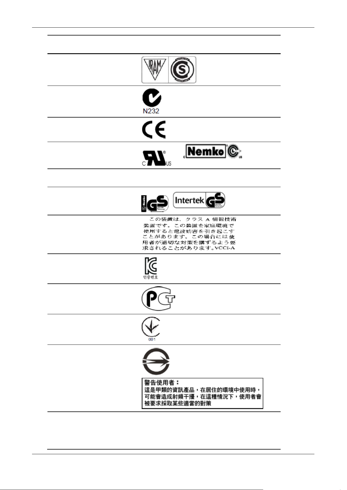
Product regulatory compliance markings
The server is provided with the following regulatory marks.
Skybox version 9.0.400 42
Page 43
Chapter 13 Regulatory and safety information
This device must accept interference receive,
Regulatory
Compliance
IRAM Argentina
Ctick Australia/
CE Mark Europe
Region Marking
NZ
NRTL (National
Recognized Test
Laboratory)
EMC Marking
(Class A)
GS Mark Germany
VCCI Marking
(Class A)
KC Mark (Korean
Communications
Commission)
GOST R Marking Russia
USA/Cana
da
Canada CANADA ICES-003 CLASS A
Japan
Korea
Ukraine
Certification
BSMI Certification
(RPC) Number &
Class A Warning
FCC Marking
(Class A)
Skybox version 9.0.400 43
Ukraine
Taiwan
USA This device complies with Part 15 of the FCC
Rules. Operation of this device is subject to
the following two conditions: (1) This device
may not cause harmful interference, and ( 2)
Page 44
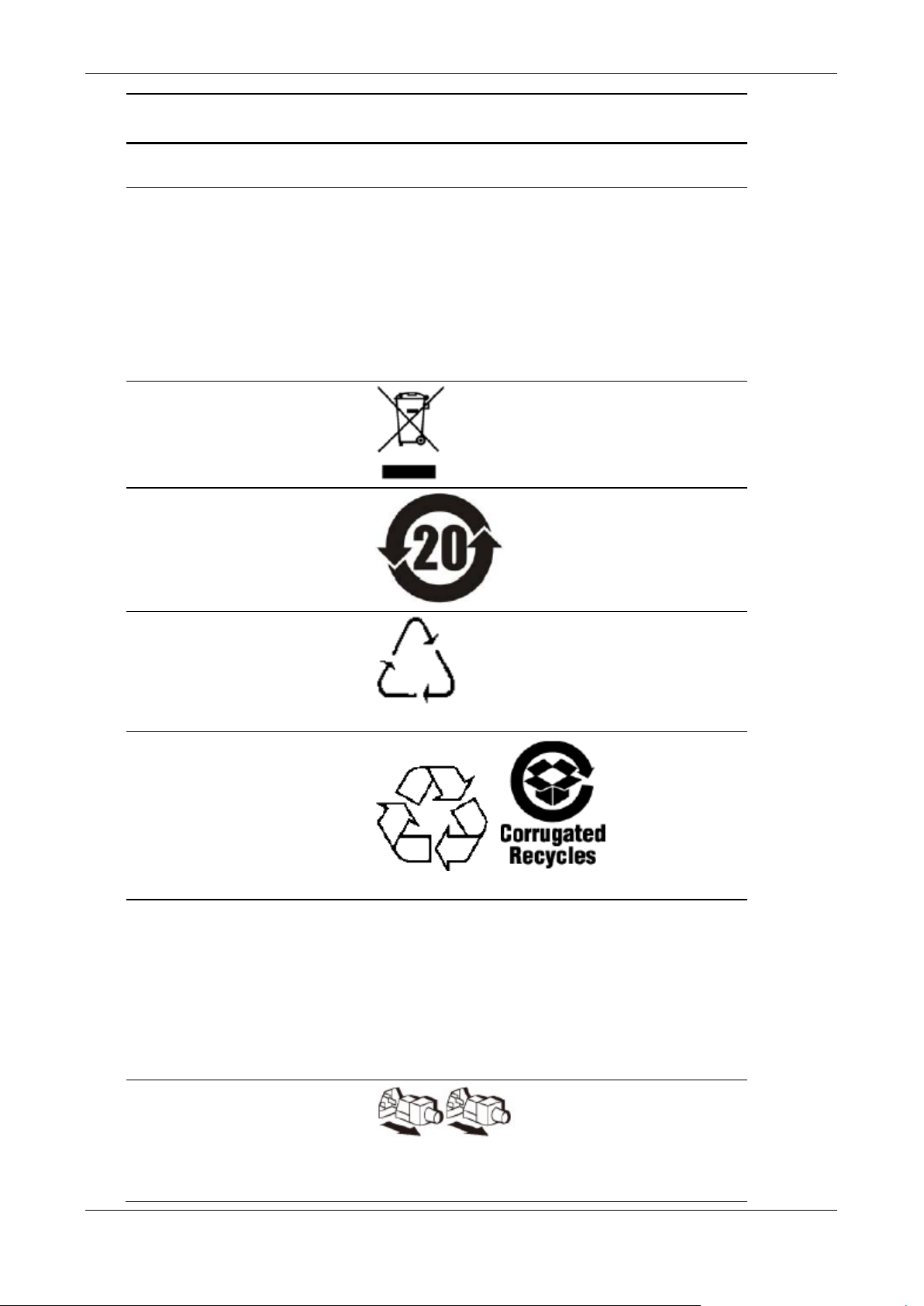
Skybox Appliance 6000 Quick Start Guide
including interference that may cause
(RoHS)
shock, disconnect (2) two power supply cords
Regulatory
Compliance
Nordic Ground Multiple Line 1: “WARNING:”
Region Marking
undesired operation
Swedish on line 2: “Apparaten skall anslutas
till jordat uttag, när den ansluts till ett
nätverk.”
Finnish on line 3: “La ite on liitettävä
suojamaadoituskoskettimilla varustettuun
pistorasiaan.”
English on line 4: “Co nnect only to a properly
earth grounded outlet.”
WEEE (Waste of
Electronic and
Electrical
Equipment)
Recycling Mark
China Restriction
of Hazardous
Substance
Environmental
Friendly Use
Period Mark
Recycling Package
Marks
Other Recycling
Package Marks
Europe
China
China
Will be added on Package label
Internatio
nal
Battery
Perchlorate
Warning
Information
Safety – Multiple
Power Cord
Skybox version 9.0.400 44
USA (CA) Perchlorate Materi a l – Special handling may
Internatio
nal
Will be added on Package label
apply. See
www.dtsc.ca.gov/hazardouswaste/perchlorate
This notice is required by California Code of
Regula tions, Title 22, Division 4.5, Chapter
33: Best Management Practices for
Perchlorate Materials. This product / part
includes a battery which contains Perchlorate
material.
English: This unit has m ore than one power
supply cord. To reduce the risk of electrical
Page 45
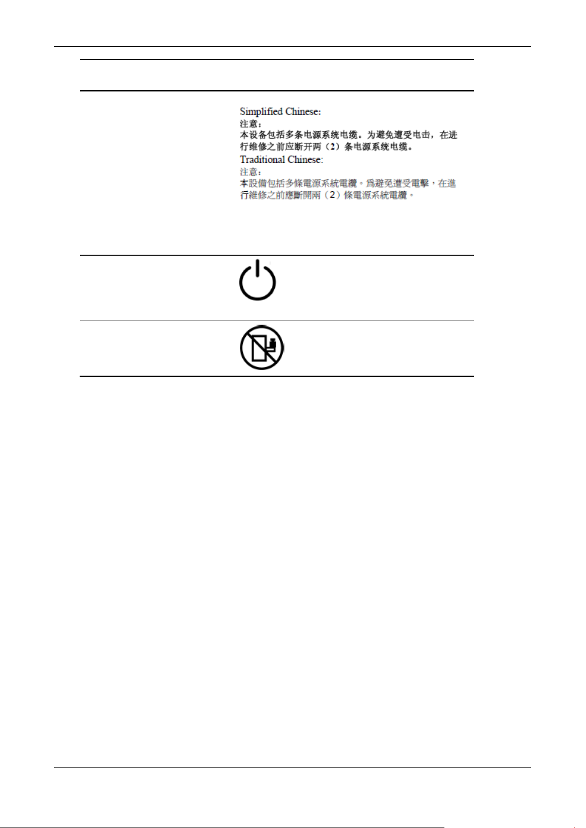
Chapter 13 Regulatory and safety information
before servicing.
Regulatory
Compliance
Region Marking
German: Dieses Geräte hat mehr als ein
Stromkabel. Um eine Gefahr des elektrischen
Schlages zu verringern trennen sie beide (2)
Stromkabeln bevor Instandhaltung.
Electromagnetic compatibility notices for the server board
Safety – Standby
Power button
Safety – Rack
Load Warning
Internatio
nal
Note: Should appear on Power button.
Internatio
nal
FCC Verification Statement (USA)
This device complies with Part 15 of the FCC Rules. Operation is subject to two
conditions: (1) This device may not cau se har mful interference, and (2) this
device must accept any interference received, including interference that may
cause undesired operation.
Intel Corporation, 5200 N.E. Elam Young Parkway Hillsboro, OR 97124-6497
Phone: 1-800-628-8686
This equipment has been tested and found to comply with the limits for a Class B
digital device, pursuant to Part 15 of the FCC Rules. These limits are designed to
provide reasonable protection against harmful interference in a residential
installation. This equipment generates, uses, and can radiate radio frequency
energy and, if not installed and used in accordance with the instructions, may
cause harmful interference to radio communication s. However, there is no
guarantee that interference will not occur in a particular installation. If this
equipment does cause harmful interference to radio or television reception, which
can be determined by turning the equipment off and on, the user is encouraged
to try to correct the interference by any of these measures:
› Reorient or relocate the receiving antenna.
› Increase the separation between the equipment and the receiver.
› Connect the equipment to an outlet on a circuit different from that to which
the receiver is connected.
› Consult the dealer or an experienced radio/TV technician for help.
Skybox version 9.0.400 45
Page 46
Skybox Appliance 6000 Quick Start Guide
Any changes or modifications not expressly approved by the grantee of this
device could void the user’s authority to operate the equipment. The customer is
responsible for ensuring compliance of the modified product.
All cables used to connect to peripherals must be shielded and grounded.
Operation with cables, connected to peripherals that are not shielded and
grounded may result in interference to radio and TV reception.
ICES-003 (Canada)
Cet appareil numérique respecte les limites bruits radioélectriques applicables
aux appareils numériques de Classe B prescrites dans la norme sur le matériel
brouilleur: “Appareils Numériques”, NMB-003 édictée par le Ministre Canadian
des Communications.
English translation of this notice:
This digital apparatus does not exceed the Class B limits for radio noise
emissions from digital apparatus set out in the interference-causing
equipment standard entitled “Digital Apparatus,” ICES-003 of the Canadian
Department of Communications.
Europe (CE Declaration of Conformity)
This product has been tested in accordance to, and complies with the Low
Voltage Directive (73/23/EEC) and EMC Directive (89/336/EEC). The product has
been marked with the CE Mark to illustrate its compliance.
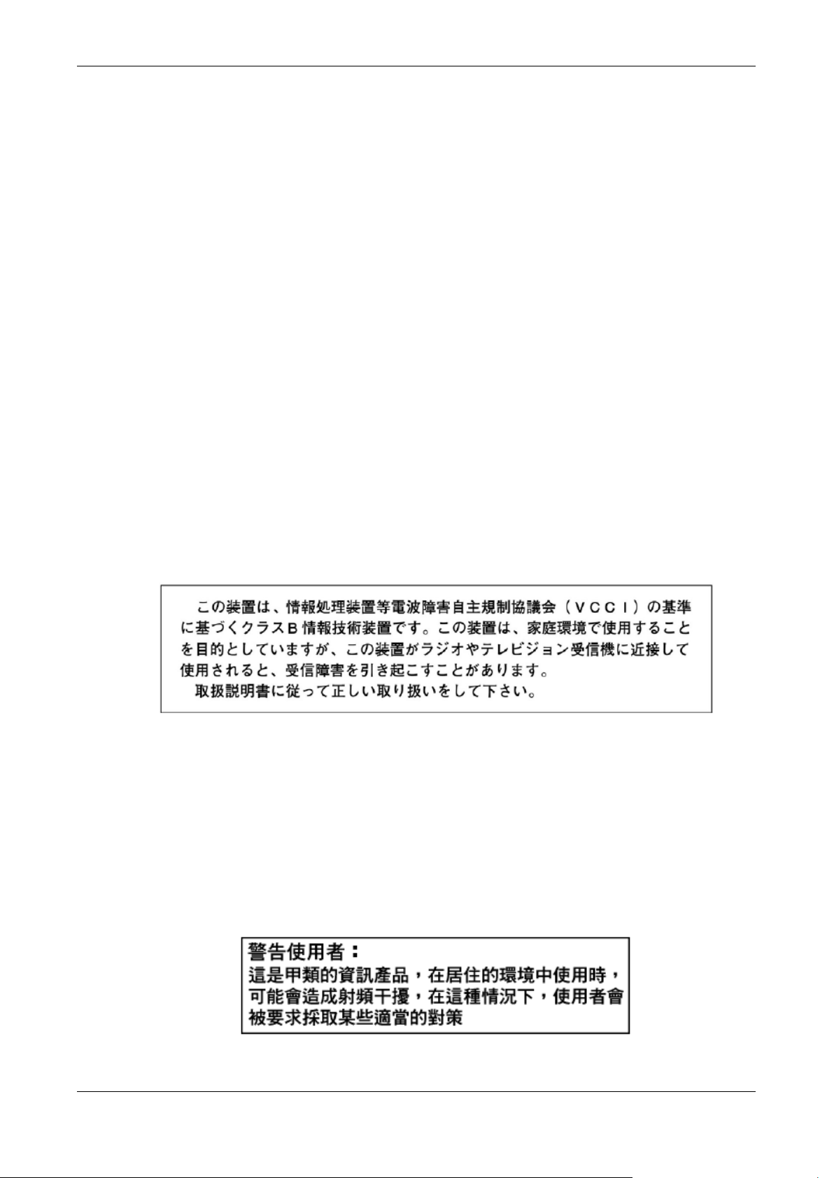
VCCI (Japan)
English translation of this notice:
This is a Class B product based on the standard of the Voluntary Control
Council for Interference (VCCI) from Information Technolog y Equipment. If
this is used near a radio or television receiver in a domestic environment, it
may cause radio interference. Install and use the equipment according to the
instruction manual.
BSMI (Taiwan)
The BSMI Certification Marking and EMC warning is located on the outside rear
area of the product.
Skybox version 9.0.400 46
Page 47

Chapter 13 Regulatory and safety information
RRL (Korea)
Following is the RRL certification information for Korea.
English translation of this notice:
1 Type of Equipment (Model Name): On L icense and Product
2 Certification No.: On RRL certificate. Obtain certificate from local Intel
representative
3 Name of Certification Recipient: Intel Corporation
4 Date of Manufacturer: Refer to date code on product
5 Manufacturer/Nation: Intel Corporation/Refer to country of origin marked on
product
CNCA (CCC-China)
The CCC Certification Marking and EMC warning is located on the outside rear
area of the product.
Skybox version 9.0.400 47
 Loading...