

Page 1
"Telecommunication Products to solve Telecommunication Problems"
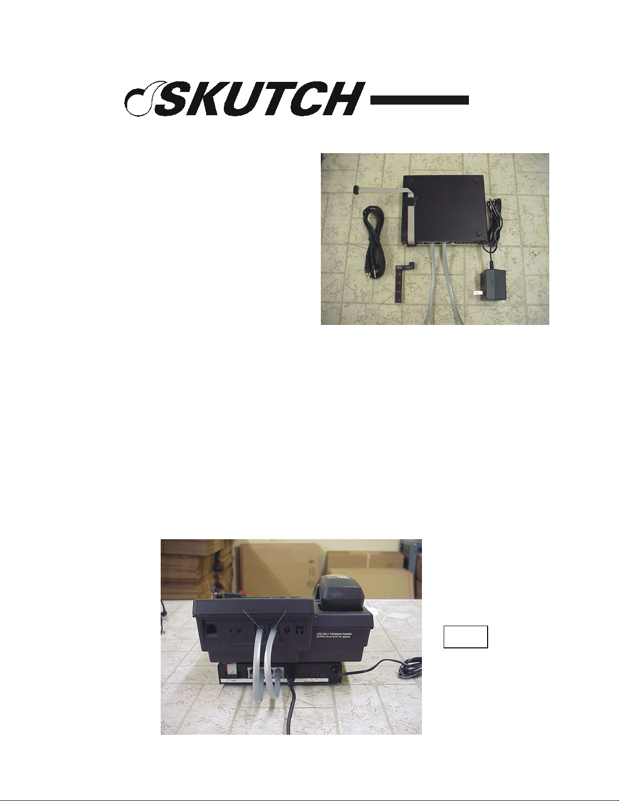
CK-1G1
Display Cable
Promotion-On-Hold
Adapter
(For 2-9451)
Audio Cable
Introduction
Thank you for purchasing the Skutch CK1G1 Promotion-On-Hold Adapter for the 29451 four line telephone. The CK-1G1 is a
Display Board
true plug and play device. The unit does not
require any "Learning" to operate. When a call is placed ON HOLD from any GE 2-9551
phone the ON HOLD caller will hear the Promotion-On-Hold audio. When the line is reanswered, the audio automatically stops. It's that simple!
Short Modular Cords
Power Cube
Loss of Dual Color Line Indicator Lights
The GE 2-9451 telephones provide dual color LINE lights (RED/GREEN). When the
CK-1G1 is used you will only have one color (RED) LINE light indication ONLY on the
telephone that the CK-1G1 is connected to.
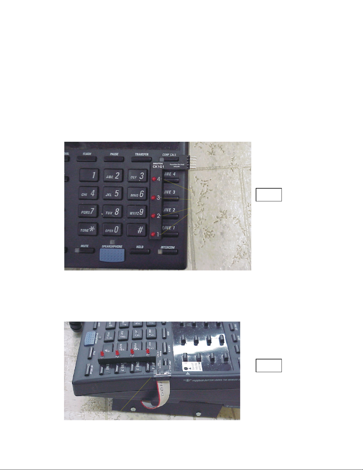
Installation
1- Position the CK-1G1 box under the base telephone with the jacks facing towards the
back of the phone as per Fig. 1.
Line 1+2
Display Cable
Line 3+4
Fig. 1
Audio Cable
Page 1 of 3
Page 2
2- Connect the short modular cord from [1&2 Phone on CK-1] to [LINE 1&2 on Phone].
3- Connect the short modular cord from [3&4 Phone on CK-1] to [LINE 3&4 on Phone].
4- Connect the audio cord from your music source, to the AUDIO IN jack on the back of
the CK-1 box. NOTE: If you are using a Digital Player, then use the audio cord that came
with your digital player. On this cord both ends have the same type of connector.
5- Connect a MOD cord from Telephone Wall Jack 1&2 to [1&2 Line on CK-1].
6- Connect a MOD cord from Telephone Wall Jack 3&4 to [3&4 Line on CK-1].
7- Locate the CK-1G1 DISPLAY BOARD, peel off the paper protector from the bottom
of the foam, and carefully align it as shown in FIG. 2. Once it is aligned properly, lightly
press down to attach it to the telephone.
Line up the dashes
on the DISPLAY BOARD
to the center of the
Line Select Buttons on
the phone.
Fig. 2
Move the board towards
Fig. 2
the right. The edge
should be touching the
edge of the buttons.
8- Connect the Display Cable from the CK-1G1 Black Box to the Display Board that is
mounted telephone. See FIG. #3.
Fig. 3
Attach Cable from Box
Page 2 of 3
Page 3

11- Connect the POWER CUBE from the CK-1 box to 115VAC power. That's it!
Testing the System:
1- Pickup line 1 on your telephone. The line one LED on the CK-1G1 Sensor should light
up.
2- Repeat this test for lines 2-4. If all lines light up when picked up, the CK-1 is working
properly. If any light does not light up, then
a) Make sure that the CK-1G1 and Phone is connected to power.
b) Make sure that the DISPLAY BOARD is aligned properly.
Lights on CK-1 Box.
When you place a line on HOLD, the corresponding LED on the rear of the CK-1G1 box
lights up to confirm the Promotion-On-Hold condition.
Using Other models of telephones
The CK-1G1 will ONLY provide Promotion-On-Hold audio when a call is placed ON
HOLD from the GE 2-9450 or 2-9451 telephones. Other models of telephones will not
clear the HOLD condition on the 2-9450 and/or 2-9451 telephones, and Promotion will
not cut off when another model attempts to pick up a HOLDING call.
Tech Support - 916-786-6186
If you have any problems getting the unit to work properly feel free to give us a call.
Technical Support is available between the hours of 7:30 AM and 4:30 PM Pacific Time,
Monday through Friday.
• ONE YEAR LIMITED WARRANTY
This SKUTCH PRODUCT is warranted against defects for a period of one (1) year from the date of the
original invoice. Within this period, we will repair it without charge for parts and labor. To obtain
warranty service the product must be returned, at the customer's expense, to SKUTCH Electronics along
with a copy of the original invoice. After the unit has been repaired, SKUTCH will ship the PRODUCT
back via UPS GROUND service at our expense. If any other form of return shipment is requested, the
customer will pay for 100% of the shipping cost.
This Warranty does not apply if in the sole opinion of SKUTCH Electronics, the PRODUCT has been
damaged by lightning or any other Acts of God, or by accident, misuse, neglect, or improper packing,
shipping, modification or servicing by other than an authorized SKUTCH Service Center.
EXCEPT AS SPECIFICALLY PROVIDED IN THIS AGREEMENT, THERE ARE NO OTHER
WARRANTIES, EXPRESSED OR IMPLIED, INCLUDING, BUT NOT LIMITED TO, ANY IMPLIED
WARRANTIES OR MERCHANTABILITIES OR FITNESS FOR A PARTICULAR PURPOSE AND IN
NO EVENT SHALL SKUTCH ELECTRONICS BE LIABLE FOR LOSS OF PROFITS OR BENEFITS,
INDIRECT, SPECIAL, CONSEQUENTIAL OR OTHER SIMILAR DAMAGES ARISING OUT OF
ANY BREACH OF THIS WARRANTY OR OTHERWISE.
Page 3 of 3
 Loading...