

Page 1
100mm
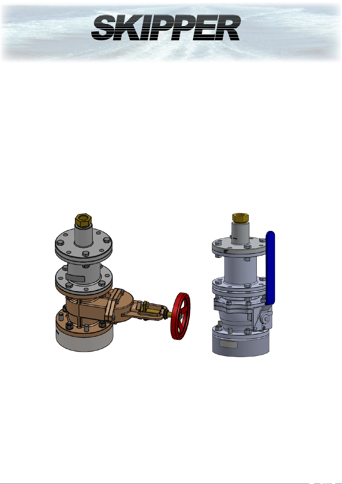
Single bottom sea valve
Installation and operation Manual
SB-100-SA
SB-100-SB
SKIPPER Electronics AS
Enebakkveien 150
P. O. Box 151, Manglerud
0612 Oslo, Norway
www.skipper.no
Telephone: +47 23 30 22 70
E-mail: [email protected]
Document no: DM-BSB100 Rev 2012
Edition: 26.08.2021
Page 2

SKIPPER Electronics AS
SB-100-XX Operation and Installation Manual
Weitergabe sowie vervielfältigung dieser unterlage, verwertung
und mitteilung ihres inhaltes nicht gestattet, soweit nicht
ausdrücklich zugestanden. Zuwiderhandlungen verpichten zu
schadenersatz.
Toute communication ou reproduction de ce document,
toute exploitation ou communication de ou son contenu sont
interdites, sauf autorisation expresse. Tout manquement à
cette règle est illicite et expose son auteur au versement de
dommeges et intèrèts.
Page2 of 24
Copying of this document, and giving it to others and the use
or communication of contents thereof, are forbidden without
express authority. Oenders are liable to the payment of
damages.
Sin nuestra expresa autorización, queda terminantemente
prohibida la reproducción total o parcial de este documento,
asì como su uso indebido y/o su exhibición o comunicación
a terceros. De los infractores Se exigirá el correspondiente
resarcimiento de daños y perjuicios.
Date: 26.08.2021
Page 3

SB-100-XX Operation and Installation Manual
SKIPPER Electronics AS
Contents
1. INTRODUCTION ........................................................................................................................ 4
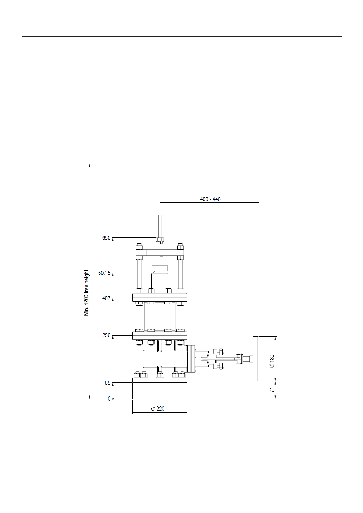
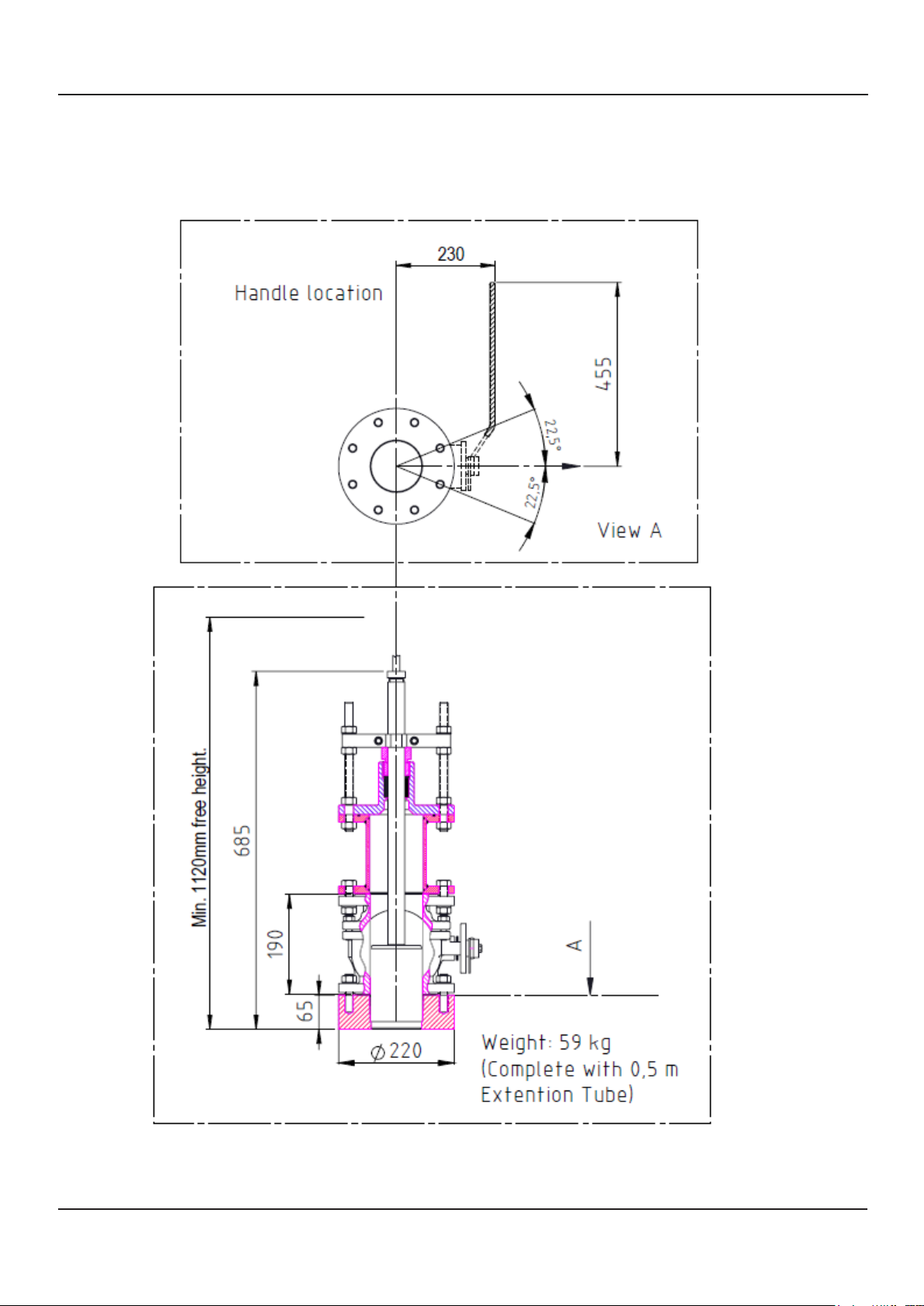
2. SPACE CONSIDERATIONS .....................................................................................................6
Space consideration SB-100-SA ...................................................................... 6
Space consideration SB-100-SB ...................................................................... 7
3. WELDING THE BOTTOM FLANGE .....................................................................................8
4. SEA VALVE ASSEMBLY. ..........................................................................................................9
Assembly SB-100-SA ...................................................................................... 9
Assembly SB-100-SB .................................................................................... 10
5. ASSEMBLING OF EXTENSION TUBE AND SENSOR ................................................... 11
6. SENSOR INSTALLATION ......................................................................................................13
7. CLAMP UNIT MOUNTING .................................................................................................... 14
8. LOWER THE SENSOR ............................................................................................................15
Lowering sensor in SB-100-SB ..................................................................... 15
Lowering sensor in SB-100-SA ..................................................................... 15
9. SENSOR FORWARD ORIENTATION .................................................................................16
10. FINAL ASSEMBLY .................................................................................................................17
11. SENSOR REMOVAL ...............................................................................................................18
12. RE-INSTALLATION ...............................................................................................................19
13. ILLUSTRATED PARTS LIST. SHIPMENT ......................................................................20
12. ILLUSTRATED PARTS LIST. ASSAMBLED ................................................................... 22
Part list SB-100-SA ........................................................................................ 22
Part list SB-100-SB ........................................................................................ 23
13. MAINTENANCE .....................................................................................................................24
Maintenance Tasks for inactive sensors ......................................................... 24
Dry docking in temperatures below freezing point ........................................ 24
Date: 26.08.2021
Page3 of 24
Page 4

SKIPPER Electronics AS
SB-100-XX Operation and Installation Manual
1. INTRODUCTION
SKIPPER SB (Single Bottom) Sea Valve 100 mm
The SKIPPER SB Sea Valve 100 mm is used for installation of: SKIPPER speed log sensors and echo
sounder transducers tted with adaptors for XB-100-XX
1. Echo Sounder transducer type (50, 200 and 50/200 kHz).
2. Speed log sensors: DL2, DL21, DL1, DL850(270kHz), EML224.
Caution!
Be aware that the Sea Valve contains high precision parts and therefore proper
handling when mounting is essential for the nal result.
When handling the Sea Valve, all lifting devices must be attached on the outside of the
valve. It is very important to not insert any chains, wire, rope or any other device into
the valve chamber. This to avoid damaging and any kind of pollution of the Sea Valve.
The SKIPPER SB Sea Valve 100 mm is delivered partly assembled for transport. The parts necessary for
nal assembly will be found packed in a box delivered with the Sea Valve. First of all, it must be decided
where the Sea Valve should be installed. Normally, this will be in the fore part of the ship, in the centerline,
or as close to the centerline as possible. Optimal system operation is achieved by tting the transducer/
sensor as deep as possible on the hull.
• The active surface of the sensor must be installed with front face a maximum of +/-1 degree to the ships
horizontal plane. (2 axis Speed Logs).
• The active surface of the transducer must be installed with front face a maximum of +/-7 degree to the
ships horizontal plane. (Echo Sounder).
Do not mount transducers close to the bow thruster propeller outlets, or aft of other hull installations (outlets,
vents or other protruding details) who may create aeration or turbulence.
It is necessary to select a part of the hull that is submerged and free from turbulence and aeration under all
load and speed conditions, and to avoid positions where air is trapped in heavy weather.
If a at, horizontal section is not available for transducer tting, the shipyard must construct a suitable bed.
Welding seams in this area should be smoothed and rounded o, in order not to create turbulence or aeration
at speed.
Protect the active element of the transducer/sensors during transport and installation, and
do not paint the surface.
The Sea Valve should be placed in a service accessible place, large enough for installation and disassembly
of the sensor unit. See drawing: “Space considerations”.
Page4 of 24
Date: 26.08.2021
Page 5

SB-100-XX Operation and Installation Manual
SKIPPER Electronics AS
Important
”Sensors for Speed Log and Echo Sounder are delivered with a xed cable. Attention must be taken
to allow easy replacement/pulling of new cable during maintenance”.
SKIPPER Electronics AS will recommend installation positions if GA-drawings (General
arrangements), lines drawings and frame drawings are made available for study.
Condition.
The welding to hull structures and structural support of the items may be subject to separate approval by
classication societies for each installation on board a ship.
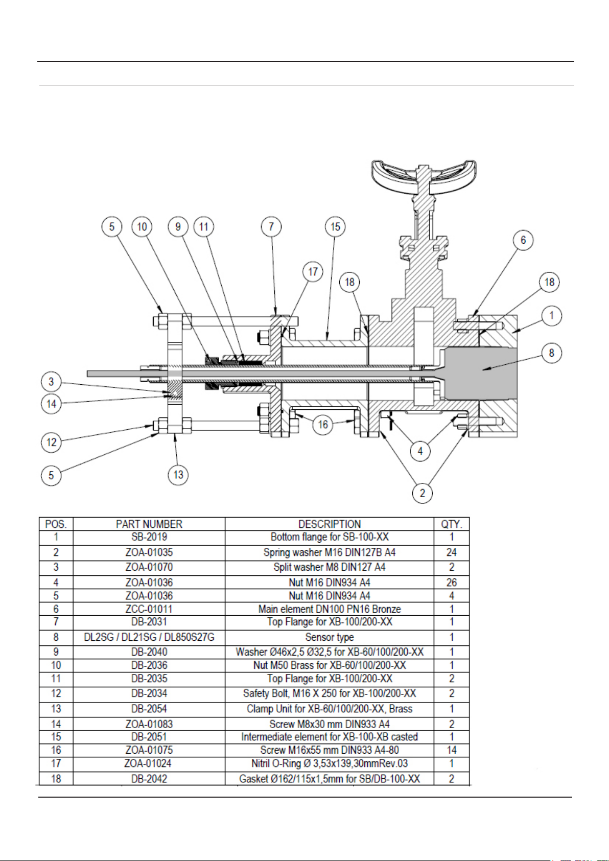
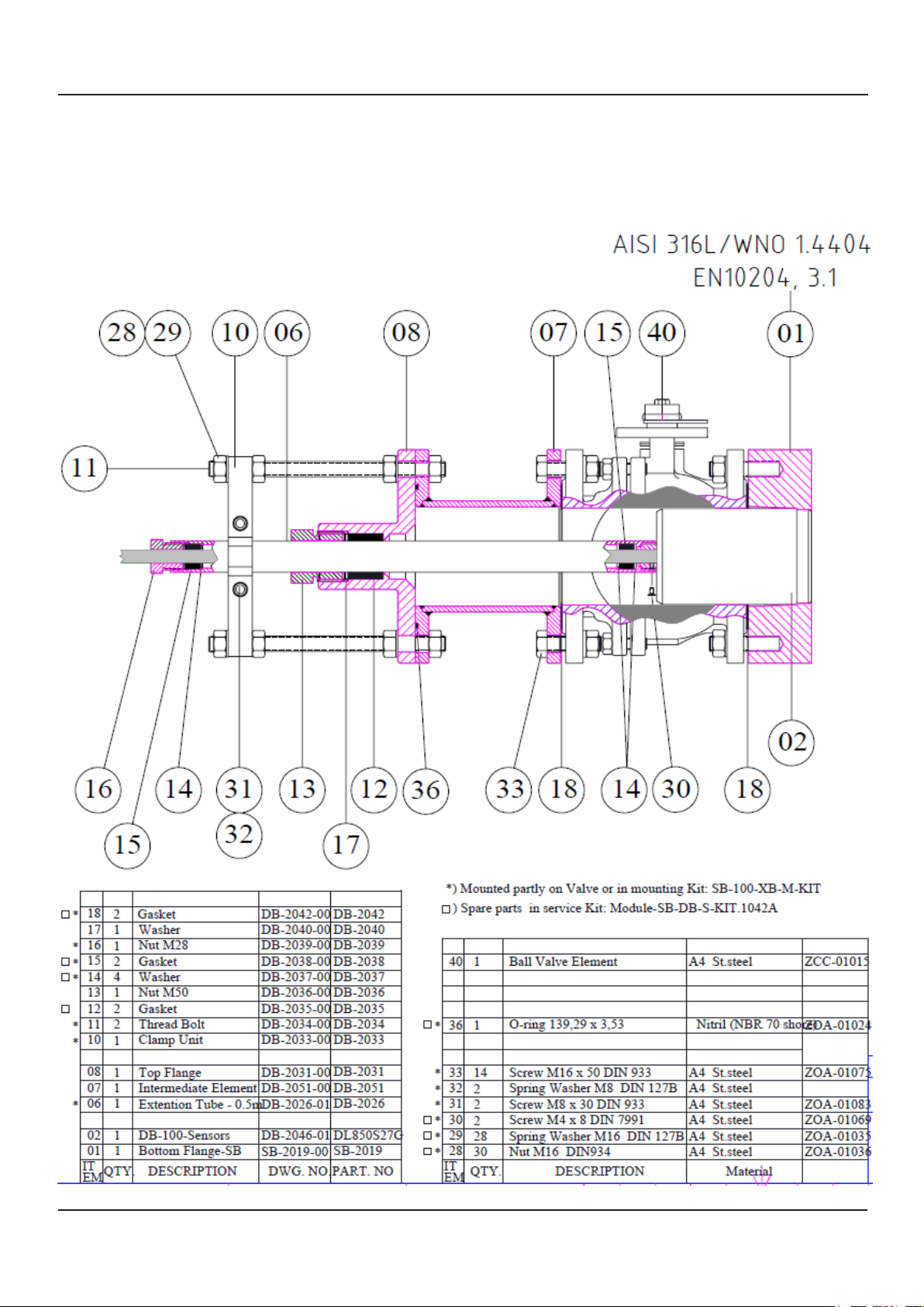
Note: All “Item numbers” references on the following pages, can be found on drawing “Illustrated parts list.
Assembled” (unless specied).
Date: 26.08.2021
Page5 of 24
Page 6
SKIPPER Electronics AS
SB-100-XX Operation and Installation Manual
2. SPACE CONSIDERATIONS
The Sea Valve should be placed in a service accessible place, large enough for installation and disassembly
of the sensor unit.
Space consideration SB-100-SA
Page6 of 24
Date: 26.08.2021
Page 7
SB-100-XX Operation and Installation Manual
Space consideration SB-100-SB
SKIPPER Electronics AS
Date: 26.08.2021
Page7 of 24
Page 8
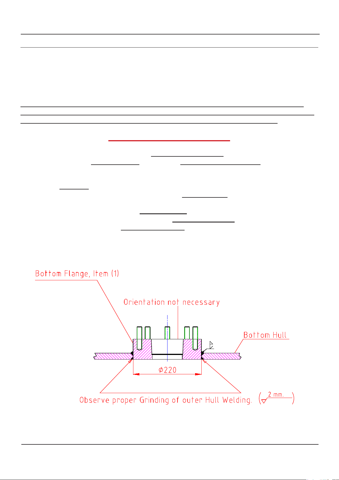
Welding the Bottom Flange in Ship`s Hull
SKIPPER Electronics AS
SB-100-XX Operation and Installation Manual
3. WELDING THE BOTTOM FLANGE
• When the position has been decided, a hole for the 220 mm bottom ange is cut in the hull.
• The bottom ange, Item (1), is welded into the hull. Standard welding practice, methods and procedures
should be observed, but may vary. (See welding notes).
Attention:
The bottom ange is a part of the Sea Valve that is machined with high accuracy and it should be
protected after mounting to avoid damage to the bottom ange surfaces. This to avoid leakage. If the
valve is pre-mounted, be sure to protect the valve from being polluted by welding debris.
WELDING NOTES!
All bottom parts and anges for welding are precisely machined parts. During welding of these parts
to the ship’s hull plates, careful attention must be paid to avoid construction strain on the bottom
parts and anges.
• Let parts cool down during welding.
• Over heating may change t and form and result in non-conformity with intended sensor/
transducer.
• Welding to thick hull steel plates will exert high stress on bottom parts and anges.
• Especially care must be taken during welding of stainless steel anges.
• Work must be performed by a qualied and certied welder.
Welding the bottom ange in ship’s hull.
8
Page8 of 24
Date: 26.08.2021
Page 9
SB-100-XX Operation and Installation Manual
SKIPPER Electronics AS
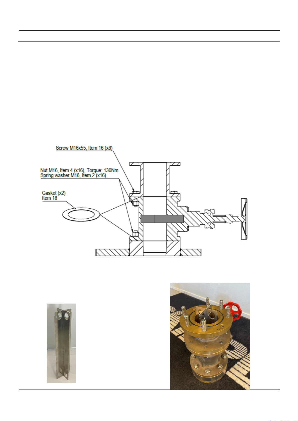
4. SEA VALVE ASSEMBLY.
Caution must be taken when mounting seavalves that all parts are aligned correctly, and that the inside is
clean. DO NOT use liguid sealants, and DO NOT paint the inside of a valve.
Assembly SB-100-SA
Step 1
• Place 1.5 mm gasket, Item (18) on top of Bottom Flange, Item (1).
• Then place the Main element, Item (6) on top of the Bottom Flange. The 16 mm nuts and washers should
be mounted, not tightened. (Align parts before tighten nuts).
• Place a 1.5 mm gasket (item 18) on top of the main element, Item (6).
• Mount the intermediate element, Item (15) on top of the main element.
Step 2
• Place the aluminium alignment tool (2 x part SB-6033 in mounting kit), all the way, into the sea valve to
ensure correct alignment of elements before bolts are tightened.
• Tighten 8 nuts valve to bottom ange.Torque: 130Nm
• Tighten 8 nuts Intermediate element to valve.
• Remove the aluminium alignment tool.
The alignment tool height
is about 37mm higher
than top of intermediate
element on the gate valve
SB-100-SA.
Date: 26.08.2021
Page9 of 24
Page 10
SKIPPER Electronics AS
SB-100-XX Operation and Installation Manual
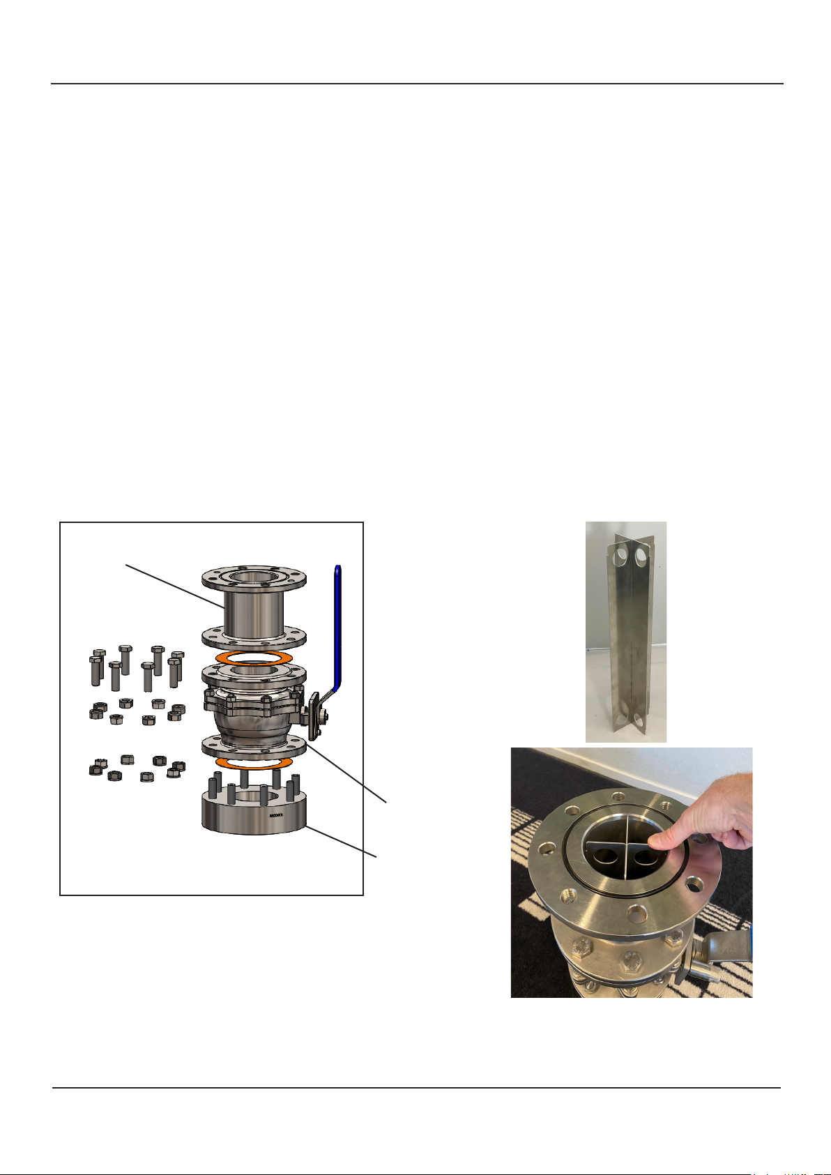
Assembly SB-100-SB
Step 1
• Place 1.5 mm gasket, on top of Bottom Flange.
• Then place the Ball Valve element on top of the Bottom Flange. The 16 mm nuts and washers should be
mounted, not tightened.
• Place a 1.5 mm gasket on top of the Ball Valve element.
• Mount the intermediate element on top of the Ball Valve element. The track for o-ring to be upwards.
• All 8 nuts and washers should be mounted, not tightened.
Step 2
• Place the aluminium alignment tube (2 x part SB-6033 in mounting kit), all the way, into the sea valve to
ensure correct alignment of elements before bolts are tightened.
• Tighten 8 nuts valve to bottom ange. Torque: 130Nm
• Tighten 8 nuts Intermediate element to valve.
• Remove the aluminium alignment tool.
Intermediate element
Step 1
Step 2
Ball valve
Bottom ange
Page10 of 24
Date: 26.08.2021
Page 11
SB-100-XX Operation and Installation Manual
SKIPPER Electronics AS
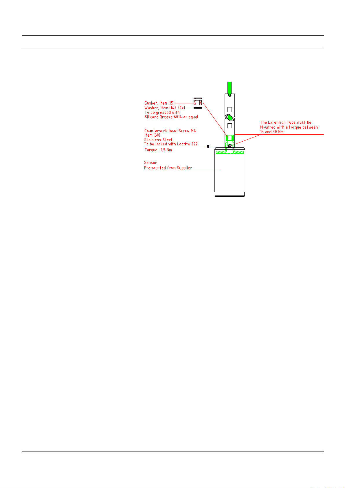
5. ASSEMBLING OF EXTENSION TUBE AND SENSOR
NOTE: Gaskets and washers are supplied as part of Speed log sensors/Echo sounder transducers
Sensor type with 11mm cable diameter:
• Echo sounders:
• ETN050G, ETN050XG,
ETN200SG, ETN200SXG
• Speed logs:
• DL2SG-SA, DL21SG-SA,
DL850S27G-SB, EML224SDB-SD,
DL1SDB-SA
Date: 26.08.2021
Page11 of 24
Page 12
?
2
3
1
4
2
3
1
4
2
3
4
1
5
POS.
PART NUMBER
DESCRIPTION
1
ZOA-01024
Nitril O-Ring Ø3,53x139,30mm
2
3
4
2
1
5
4
?
3
Assembled view
2
3
1
4
SKIPPER Electronics AS
SB-100-XX Operation and Installation Manual
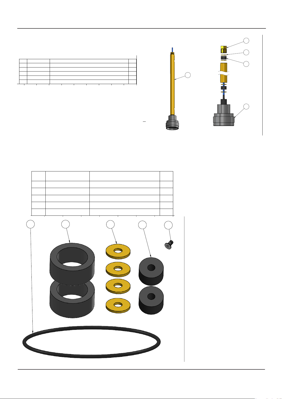
Sensor type with 7mm cable diameter:
• Echo sounders:
• ETS50200G-SA, ETS50200XG-SA.
POS.
PART NR.
1 ETS50200-SA
DB-2039
2
3
DB-2026
DB-2020
4
5
DB-2019
Transducer 50/200kHz in 100mm housing w/25m cable
Pos 2 and 3
Included with sea valve.
Mounting kit SB-100-SB-M-KIT
Pos 4 and 5
Included with the sensor.
Sensor installation kit INSTKITVALVE100-7mm
Kit INSTKITVALVE100-7mm
With every sensor is included a kit
Pos 1 and 2. O-ring and gaskets to be replaced with every sensor replacemet.
Pos 3 and 4. Washer and gasket used with 7mm
DESCRIPTION
Nut M28 Brass
Extension Tube 0,5m SB-100
Gasket Ø25,9x15 ø8
Washer Brass Ø25,9 ø9 x2,5mm
QTY.
1
1
1
2
4
Assembled view
2
5
4
3
1
POS.
1
2
3
4
5
1
PART NUMBER
ZOA-01024
DB-2035
DB-2019
DB-2020
ZOA-01069
2
Nitril O-Ring Ø3,53x139,30mm
Gasket Ø47/32,5 X 20mm
Washer Ø25,9/ø8 x 2,5mm
Gasket Ø25,9/8 x15mm
Screw M4x8 mm DIN7991 A4
3
DESCRIPTION
1
2
4
2
1
QTY.
4
5
Page12 of 24
Date: 26.08.2021
Page 13
Sensor installation
SB-100-XX Operation and Installation Manual
6. SENSOR INSTALLATION
SKIPPER Electronics AS
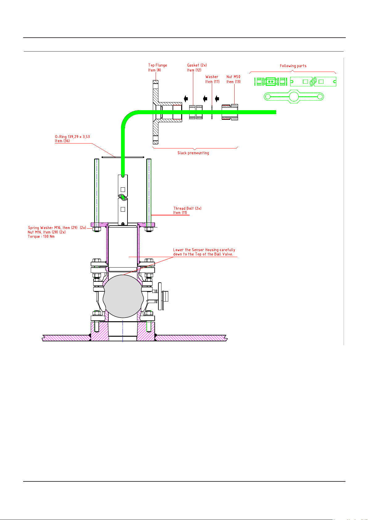
• Place the O-ring, Item (36) in the groove on top of the intermediate element, Item (7).
• Apply grease to the O-ring.
• Insert the 2 thread bolts, Item (11) through the ange and secure with 2 x M16 counter nuts, Item (28).
• Torque 130 Nm.
• Lower the sensor housing carefully down to the top of the valve piston.
Date: 26.08.2021
Page13 of 24
Page 14
Clamp Unit mounting
SKIPPER Electronics AS
7. CLAMP UNIT MOUNTING
SB-100-XX Operation and Installation Manual
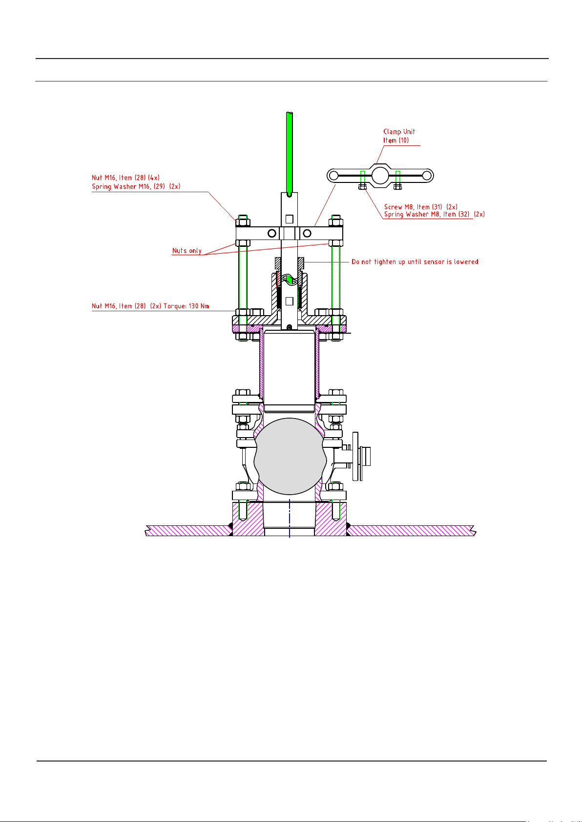
Mount Top Flange, Item (8). Secure with 8 washers, Item (29) and nuts, Item (28). Torque: 130 Nm.
Mount in following order:
• 2 x gasket, Item (12).
• Washer, Item (17).
• Nut M50, Item (13).
• 2 x M16 nuts, Item (28 ).
• Clamp Unit, Item (10).
• 2 x M16 nuts, Item (28) with spring washer, Item (29).
Page14 of 24
Date: 26.08.2021
Page 15
SB-100-XX Operation and Installation Manual
SKIPPER Electronics AS
8. LOWER THE SENSOR
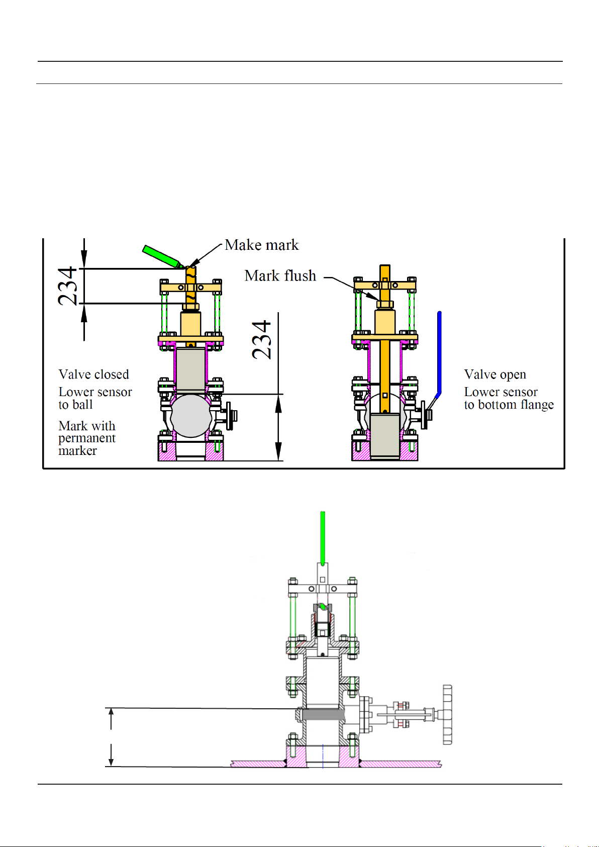
• To ensure sensor is properly inserted completly into the bottom ange make a distance mark to indicate
when the sensor is at bottom.
• SB-100-SB/SB-100-LB distance from top of ball to bottom: 234mm
• SB-100-SA/SB-100-LA distance from top of gate to bottom: 180mm
• Before opening the sea valve. Lift up the sensor some cm to avoid scratches when valve opens.
• Open Sea Valve, lower sensor unit and Extension Tube.
Lowering sensor in SB-100-SB
180mm
Lowering sensor in SB-100-SA
Date: 26.08.2021
Page15 of 24
Page 16
SKIPPER Electronics AS
SB-100-XX Operation and Installation Manual
9. SENSOR FORWARD ORIENTATION
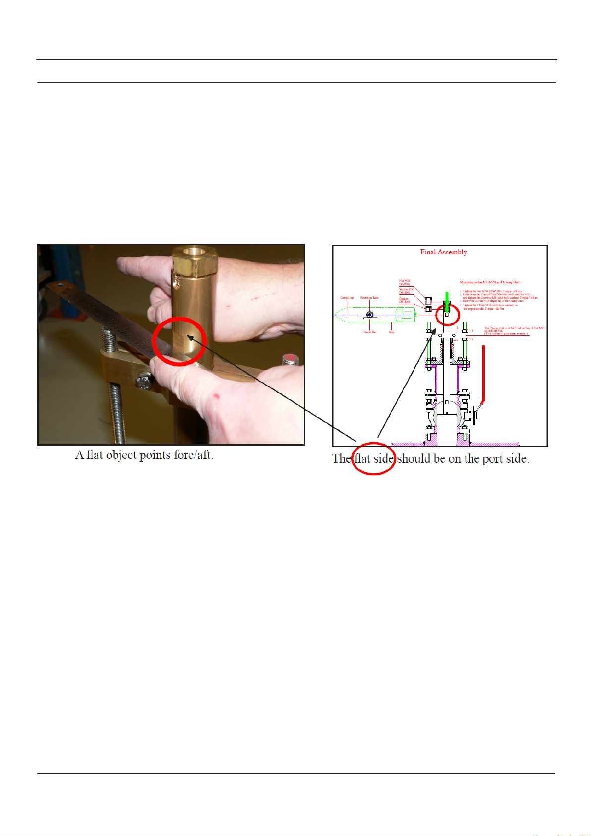
• Sensor forward orientation only required for Speed Logs. Echo sounder transducers requires no forward
orientation.
• Rotate the Extension Tube to align the sensor to point forward (ahead),. Use the attened area on the
Extension Tube to nd correct direction.
Page16 of 24
Date: 26.08.2021
Page 17
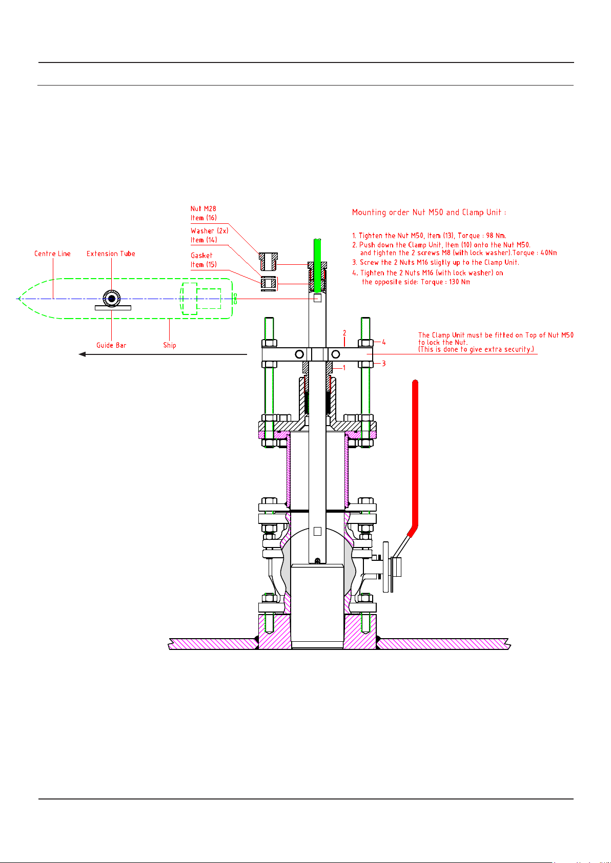
SB-100-XX Operation and Installation Manual
10. FINAL ASSEMBLY
• Tighten nut M50
• Push down clamp unit on to the nut M50
• Tighten the 2 screws M8 on the clamp unit
• Tighten the nuts M16
SKIPPER Electronics AS
Forward (Ahead)
Protect sensor!
• When launching ship, lift sensor 50 mm.
• When dry docking ship, lift sensor 50 mm.
Check that the transducer sensor housing, when fully inserted, is ush with the lower surface of the
bottom ange.
Date: 26.08.2021
Page17 of 24
Page 18
SKIPPER Electronics AS
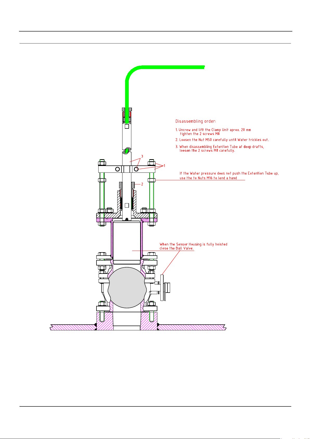
11. SENSOR REMOVAL
SB-100-XX Operation and Installation Manual
Page18 of 24
Date: 26.08.2021
Page 19
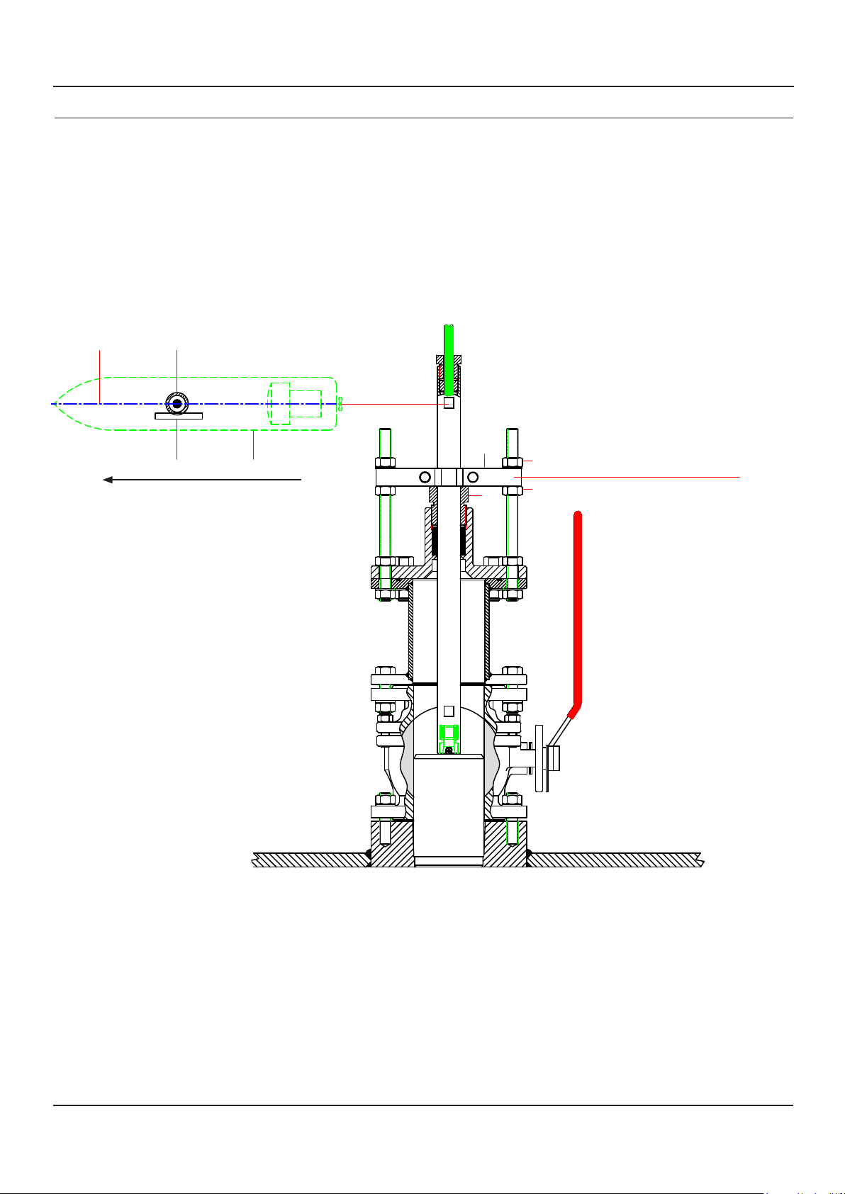
Reinstallation
The Clamp Unit must be fitted on Top of Nut M50
SB-100-XX Operation and Installation Manual
12. RE-INSTALLATION
Extension TubeCentre Line
Same procedure as first-time mounting.
Mounting order Nut M50 and Clamp Unit :
1. Tighten the Nut M50, Item (13), Torque : 98 Nm.
2. Push down the Clamp Unit, Item (10) onto the Nut M50.
and tighten the 2 screws M8 (with lock washer).Torque : 40Nm
3. Screw the 2 Nuts M16 sligtly up to the Clamp Unit.
4. Tighten the 2 Nuts M16 (with lock washer) on
the opposite side: Torque : 130 Nm
SKIPPER Electronics AS
Guide Bar Ship
Forward (Ahead)
2
1
4
3
to lock the Nut.
(This is done to give extra security.)
Date: 26.08.2021
Page19 of 24
Page 20
SKIPPER Electronics AS
SB-100-XX Operation and Installation Manual
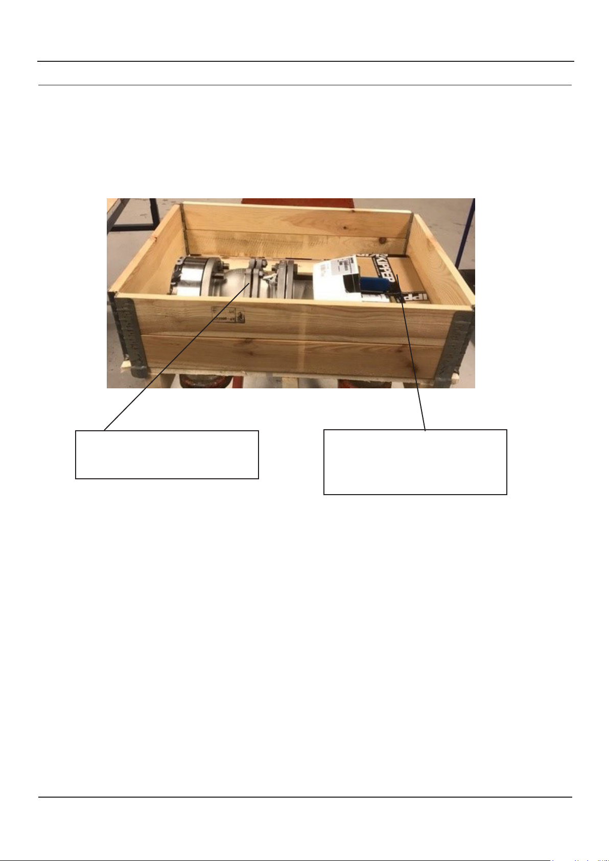
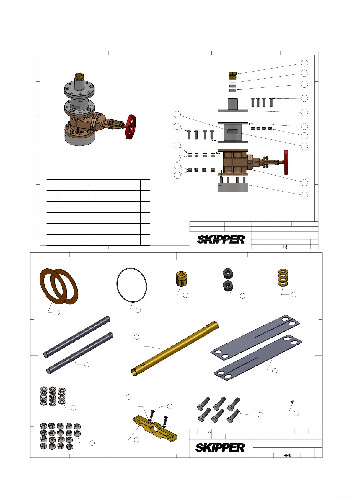
13. ILLUSTRATED PARTS LIST. SHIPMENT
The SB-100-SA and SB-100-SB sea valves are packed in a wooden pallet.
Dimmensions: 60 x 80 x 52cm
Ball valve SB-100-SB: 86kg
Gate valve SB-100-SA: 78kg
Sea valve partly assembled.
Ball valve: SB-100-PB
Gate valve SB-100-PA
SB-100 mounting kit.
SB-100-SB-M-KIT
This kit is the same for gate valve
and ball valve.
Page20 of 24
Date: 26.08.2021
Page 21
ISO2768m
1 : 5
2021.04.23
1 of 1
SB-100-XX Operation and Installation Manual
SKIPPER Electronics AS
A
B
C
D
E
F
1
POS.
PART NUMBER
1 SB-2019
2
DB-2036
3
DB-2035
4
DB-2031
5
DB-2040
6
ZOA-01035
7
ZOA-01036
8
ZCC-01011
ZZA-01127
9
10
DB-2051
11
ZOA-01075
1
1
2
DESCRIPTION
Bottom flange for SB-100-XX
Nut M50 Brass for XB-60/100/200-XX
Gasket Ø47/32,5 X 20mm
Top Flange for XB-100/200-XX
Washer Ø46x2,5 Ø32,5
Spring washer M16 DIN 127B A4
Hexagon Nut ISO 4034 - M16 - N
Main element DN100 PN16
Metalised polyester laser label
Intermediate element
Screw M16x55 DIN933 A4-80
2
2
3
3
4
5
6
7
8
2
A
5
3
B
11
9
11
6
4
6
C
7
10
7
7
D
6
QTY.
1
1
2
1
8
1
E
1
12
12
1
1
1
3
8
4
4
Rev.01 Changed Intermediate element
from SB-3021 to DB-2051 and updated
CN
parts list. ST 2020.02.26
Designed by - date
ST 2020.02.26
5
Checked by
Electronics AS
Changed description on
Pos.3 DB-2035
ST 2021.04.23
Approved by - date
GT 2020.02.26
6
Material
N/A
Name
Sea Valve 100mm, Single bottom,Partly assembled
Drwg. no.
Gen. tolerance
SB-100-PA
Eur. projection
7
Scale
Edition date
8
Revision
01
Sheet
A
5
3
DB-2039
B
2
1
DB-2042
Gasket
Ø162/115x1,5mm for
SB/DB-100-XX
2x
C
6
DB-2034
Safety Bolt, M16 X 250
D
E
F
1
for XB-100/200-XX
10
ZOA-01035
Spring washer M16
DIN127B A4
14x
Nut M16 DIN934 A4
2
2x
9
ZOA-01036
18x
3
ZOA-01024
Nitril O-Ring
Ø3,53X139,30mm
1x
8
DB-2026
Extention Tube 0,5m
DB-100/DB-60
1x
7
ZOA-01070
Split washer M8
DIN127 A4
2x
7
DB-2054
Clamp Unit for XB-
60/100/200-XX, Brass
1x
4
Nut M28 Brass for
XB-60/100/200-XX
7
ZOA-01083
Screw M8x30 mm
DIN933 A4
2x
1x
12-021/022 New drw.
2012.09.07 HK
CN
Designed by - date
HK 2012.09.10
Made new edition to include -XA
version too. Made folder under /09
2
ST 2020.02.25
Checked by
ST
4
Gasket Ø25,9/12x15mm
for XB-60/100/200-XX
Rev. 03 Added part SB-6033 Allignment
tool, aluminium. 2 pcs.
ST 2021.08.27
Approved by - date
GT 2021.08.27
DB-2038
2x
12
ZOA-01075
Screw M16x55 mm
DIN933 A4-80
6x
Material
N/A
Name
Mounting Kit for SB-100-XX
Drwg. no.
SB-100-SB-M-KIT
Gen. tolerance
ISO2768m
13
SB-6033-01
Alignment tool,
aluminium for
SB-100-XX
Eur. projection
DB-2037
Washer M25,9x2,5 Ø13
for XB-60/100/200-XX
4x
2x
11
ZOA-01069
Screw M4x8 mm
DIN7991 A4
Edition date
Scale
2021.08.27
1:2
A
B
C
D
E
1x
Revision
03
Sheet
1 of 1
Date: 26.08.2021
Page21 of 24
Page 22
SKIPPER Electronics AS
SB-100-XX Operation and Installation Manual
12. ILLUSTRATED PARTS LIST. ASSAMBLED
Part list SB-100-SA
Page22 of 24
Date: 26.08.2021
Page 23
SB-100-XX Operation and Installation Manual
SKIPPER Electronics AS
Part list SB-100-SB
Date: 26.08.2021
Page23 of 24
Page 24

SKIPPER Electronics AS
SB-100-XX Operation and Installation Manual
13. MAINTENANCE
1: Speed log performance may be eected by growth, shell, etc on sensor head.
Sensors may need carefully cleaned for growth to regain performance.
2: Sea valves consist of moving mechanical parts.
Greasing of mechanical parts may be considered to ensure operation and avoid corrosion.
Sea valves installed in wet areas (ballast tank etc) should be regularly inspected and greased.
3: Dry docking.
Gaskets and o-rings may be considered to be replaced during dry docking period.
Inspection of sea valve operation should be considered before a dry docking period to have any spare parts
available at dry docking.
4: O-rings are included with sensors and should be replaced when/if sensor is replaced.
Maintenance Tasks for inactive sensors
(If the system is to be o / and the vessel static for over 6 months (cold water), 3 months warm water).
When closing the vessel.
• Turn o unit at power, both Display and transceiver.
• Mark the alignment of the sensor on the gate valve and sensor ange/pole.
• Lift the sensor into the gate valve and close the valve.
• Grease the valves external moving parts
When restarting
• Heat the areas containing display, to allow condensation to evaporate.
• Lift and inspect the sensor head (or send diver). Carefully clean away growth.
• Redeploy the sensor taking care with alignment.
• Start the system.
• On rst test, check alignment (Head Err in the calibration screen).
Dry docking in temperatures below freezing point
If vessel is to be dry docked in temperatures below freezing point water remained inside sea valve may cause
damage to sea valve or sensor/transducer.
Page24 of 24
Date: 26.08.2021
 Loading...