

Page 1
DL2
Dual Axis Doppler Speed Log System (SOG+STW)
Installation Manual
SKIPPER Electronics AS Telephone: +47 23 30 22 70
Enebakkveien 150 Telefax: +47 23 30 22 71
P. O. Box 151, Manglerud E-mail: [email protected]
0612 Oslo, Norway Co. reg. no: NO-965378847-MVA
www.skipper.no
Document no: DM-M002-SA
Rev: 1723A
Date: 2018-05-28
(for softwares up to 1.0.14 &1.1.0)
BRIDGE
FORE PEAK
115-230VAC
/ 24VDC
DL21SG-SA
DL21 sensor
w/40m cable
in Sea valve
SB-100-SB
JB21-SA
Junction box
JB70D21-SA
Electronic Unit
Sensor extension cable.
Yard supply.
6 x twisted shielded pairs
Dimension: see DL2 manual Chapter 3.
JB12-SA
Junction box
DL2SG-SA
DL2 sensor
w/40m cable
in Sea valve
SB-100-SB
JB70D2-SA
Electronic Unit
Sensor extension cable.
Yard supply.
3 x twisted shielded pairs
Dimension: see DL2 manual Chapter 3.
CU-M001-SA Operator Unit for DL2
LAN cable. CAT6. Max. 100m
24VDC
Page 2

Page 2 of 60
2018-05-28
Installation DL2 Doppler Speed Log System
INSTALLATION MANUAL
DL2
DUAL AXIS DOPPLER SPEED LOG SYSTEM
Copying of this document, and giving it to others and the use
or communication of contents thereof, are forbidden without
express authority. Offenders are liable to the payment of damages.
Sin nuestra expresa autorización, queda terminantemente
prohibida la reproducción total o parcial de este documento,
asì como su uso indebido y/o su exhibición o comunicación
a terceros. De los infractores se exigirá el correspondiente
resarcimiento de daños y perjuicios.
Weitergabe sowie vervielfältigung dieser unterlage, verwertung und mitteilung ihres
Inhaltes nicht gestattet, soweit nicht ausdrücklich zugestanden. Zuwiderhandlungen
verpichten zu schadenersatz.
Toute communication ou reproduction de ce document, toute Exploitation ou
communication de ou son contenu sont interdites, sauf autorisation expresse.
Tout manquement à cette règle est illicite et expose son auteur au versement de
dommeges et intèrèts.
Page 3

2018-05-28
Page 3 of 60
Installation DL2 Doppler Speed Log System
COMMUNICATING WITH US
If you need more information, support or other assistance from us, do not hesitate to contact us:
SKIPPER Electronics AS
P. O. Box 151, Manglerud
NO-0612 Oslo
Norway
Phone: (+47) 23 30 22 70, Fax: (+47) 23 30 22 71
E-mail: [email protected]
SOFTWARE UPDATES AND TECHNICAL SUPPORT
Find us on the internet: www.skipper.no
YOUR FEEDBACK IS APPRECIATED
If you nd errors, misspellings or poorly explained sections in this document, please do not hesitate
to contact us at:
Page 4

Page 4 of 60
2018-05-28
Installation DL2 Doppler Speed Log System
CONTENTS
TERMINOLOGY ......................................................................................................................... 5
Terms used in this manual ................................................................................................................................... 5
CHAPTER 1: GETTING STARTED ........................................................................................... 7
Overview DL2 ...................................................................................................................................................... 7
Optional items DL2 .............................................................................................................................................. 8
Items Not supplied by SKIPPER ......................................................................................................................... 9
Power supply requirements ................................................................................................................................. 9
CHAPTER 2: HARDWARE MOUNTING ................................................................................... 10
Placement of the Operator unit ........................................................................................................................... 10
Placement of the electronic unit .......................................................................................................................... 11
Placement of the electronic unit IP22 approved .................................................................................................. 11
Placement of JB12 Junction box ......................................................................................................................... 11
Placement of repeaters ....................................................................................................................................... 11
Placement of the sea valve ................................................................................................................................. 12
Placement of the Sensor in sea valve ................................................................................................................. 13
CHAPTER 3: WIRING ................................................................................................................ 16
Clamping the cables ............................................................................................................................................ 16
CU-M001-SA Operator unit wiring ....................................................................................................................... 17
JB70D2-SA Electronic Unit Wiring ...................................................................................................................... 18
Connectors supplied with JB70D2 ...................................................................................................................... 19
SENSOR CONNECTION J3 ............................................................................................................................... 20
NMEA CONNECTION J1 .................................................................................................................................... 21
AUX/Alarm CONNECTION J2 ............................................................................................................................. 22
Additional NMEA, Aux and analog Out ................................................................................................................ 22
Yard supplied extension cable from sensor to JB70 Electronic unit. ................................................................... 23
The junction box (JB12)/splice ............................................................................................................................ 23
CHAPTER 4: SETUP PROCEDURE ......................................................................................... 26
CONFIG .............................................................................................................................................................. 27
CU-M001 setup ................................................................................................................................................... 28
JB70D2 setup ...................................................................................................................................................... 29
DL2 setup ............................................................................................................................................................ 30
Reset .............................................................................................................................................................. 33
Software options............................................................................................................................................. 34
Communications setup (NMEA/UDP) ................................................................................................................. 36
NMEA ............................................................................................................................................................. 36
LAN UDP ........................................................................................................................................................ 36
NMEA sentences received ............................................................................................................................. 38
NMEA sentences transmitted ........................................................................................................................ 39
Alarm/Alert setup ................................................................................................................................................. 40
Setup AUX ........................................................................................................................................................... 44
System Diagnostics ............................................................................................................................................ 45
Available options in the diagnostic page ............................................................................................................. 45
Error messages ................................................................................................................................................... 45
Saving and locking ............................................................................................................................................. 46
Status LEDs ....................................................................................................................................................... 46
Hardware options ................................................................................................................................................ 47
CHAPTER 6: SOLVING PROBLEMS ........................................................................................ 48
Software upgrade ................................................................................................................................................ 48
APPENDIX 1: INSTALLATION DRAWINGS ............................................................................. 49
APPENDIX 2: DATA SHEETS ................................................................................................... 55
APPENDIX 3: MULTI EXTENSION PCB ................................................................................... 58
APPENDIX 4: CONNECTING 2 SYSTEMS .............................................................................. 59
APPENDIX 4: COMMISIONING CHECKLIST ........................................................................... 60
Page 5
2018-05-28
Page 5 of 60
Installation DL2 Doppler Speed Log System
TERMINOLOGY
Terms used in This manual
_________________________________________________________
Units
Unless otherwise stated, all values shown on the display are as follows:
Speed Knots
Distance (Vessel) Nautical miles
Depth Meters
Tilt ° Degrees
Temperature ° Centigrade
Rotation Degrees per minute
Heading Degrees
Abbreviations
In addition, the following symbols are used
WT Water track
BT Bottom track
STW Speed through water
SOG Speed over ground
Trip Text for trip/total
ECDIS Electronic Chart Display and Information System
INS Inertial Navigation System
VDR Voyage Data Recorder
ROT Rotation from Gyro
GYRO Gyroscopic heading / rotation sensor
HDG Heading
DL2 2 Axis Doppler Log (with speed over bottom and Speed through water)
DL1 1 Axis speed through water sensor (part of DL21 system)
DL21 A system with combined DL1 and DL2 in the same housings
UDP User Datagram Protocol.
SFI System function Id
LAN Local Area Network
Symbols
In addition, the following symbols are used
Indicating that the information presented is partly from the GPS input, and therefore not
from this sensor. (Outputs may show invalid data in this mode)
Symbolising that the data presented is longitudinal (forward or backwards)
Symbolising the data is transversal (port or starboard)
Page 6
Page 6 of 60
2018-05-28
Installation DL2 Doppler Speed Log System
Alarm active. Unacknowledged (ashing)
Alarm active. Silenced (ashing)
Alarm active. Acknowledged
Alarm active - Responsibility transferred alarm
Alarm rectied - Unacknowledged
Simulator mode - The system is using a simulator to generate the speed and depth
Option - Mute mode. The system has a sync option activated and is currently being
muted (No acoustics)
Symbolising the resultant speed direction
Page 7
2018-05-28
Page 7 of 60
Installation DL2 Doppler Speed Log System
CHAPTER 1: GETTING STARTED
Overview dl2
The DL2 dual axis Doppler speed log is a Navigational Doppler Speed log system that measures
speed in two axis (longitudinal and transversal) through the water and over the sea bed. The system
requires no external inputs, however adding inputs from other navigational systems enhances the
functionality and allows comprehensive quality control of the data.
The system fullls all class and type regulations based on MED B (wheelmark) and is manufactured
in Norway under stringent production controls.
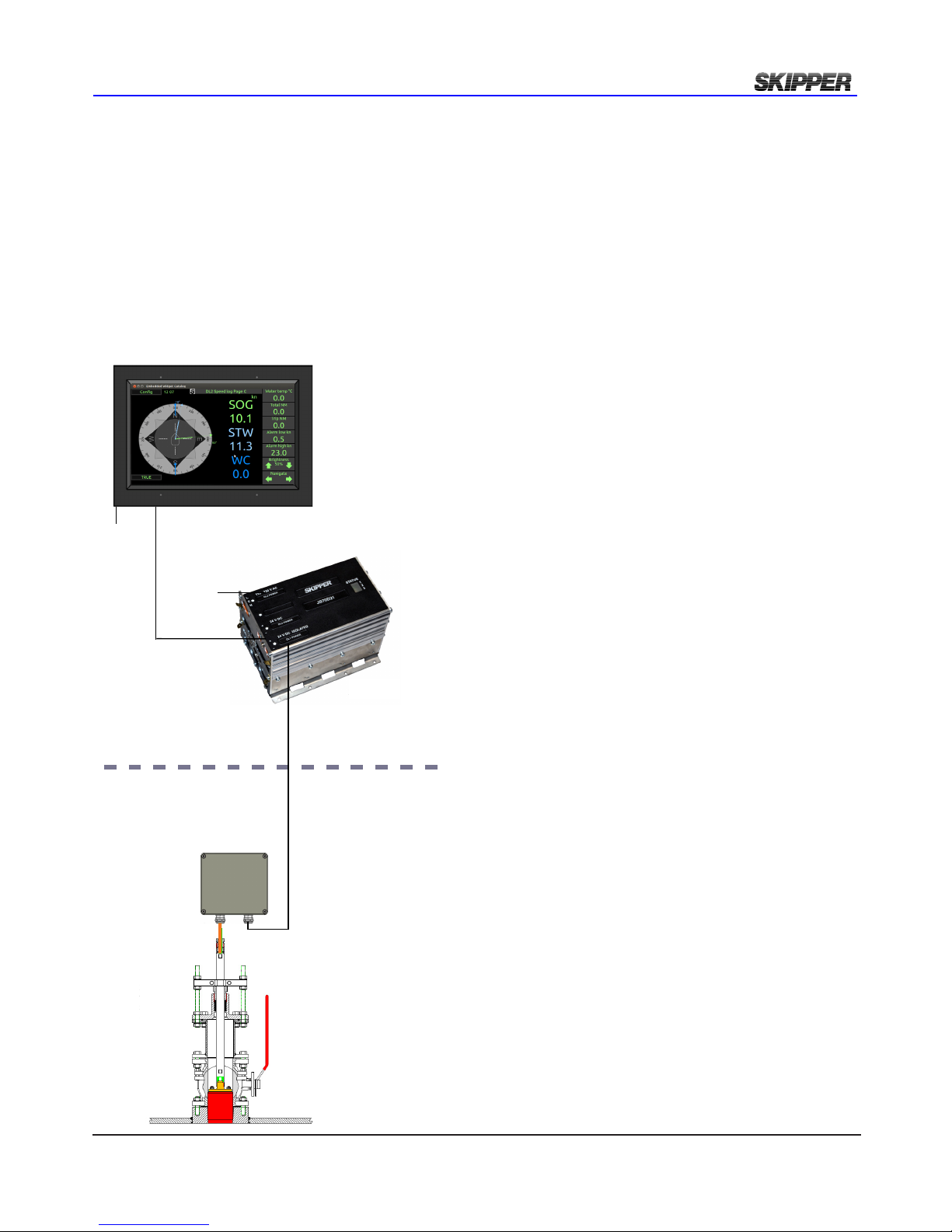
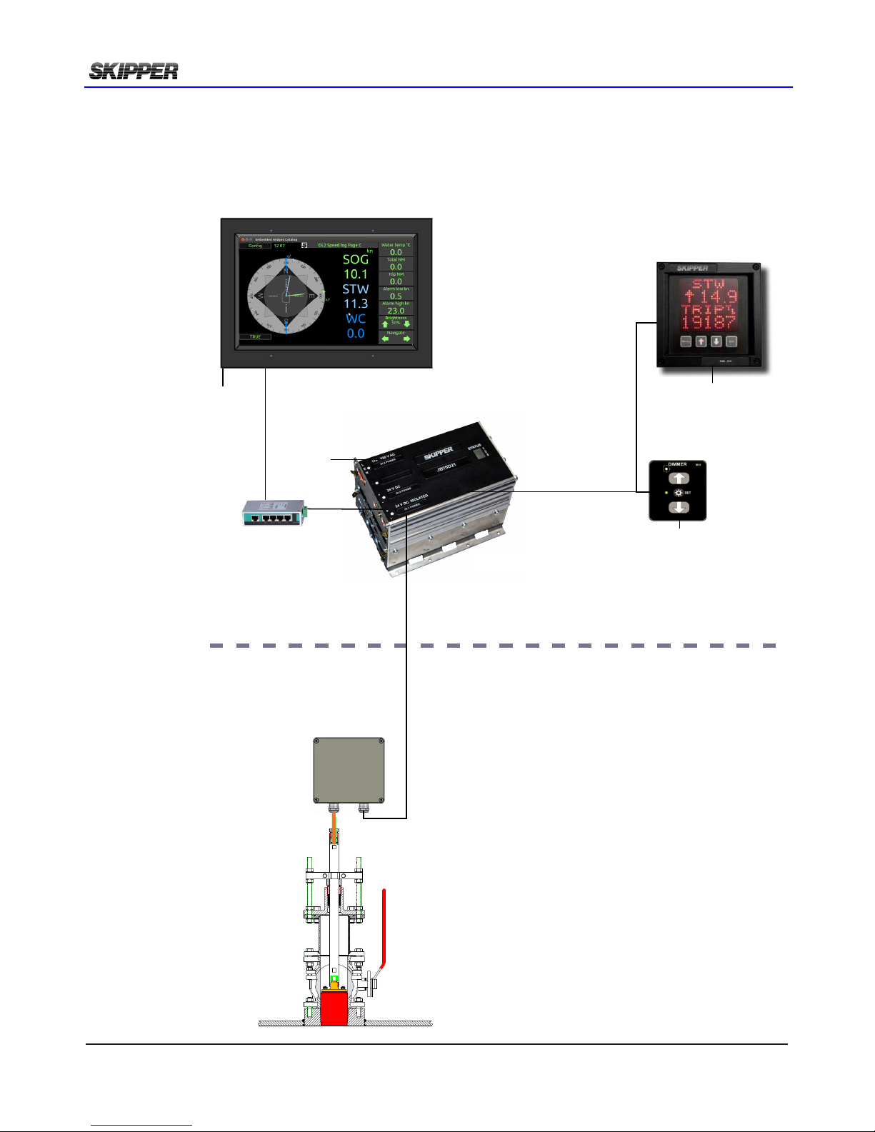
The system comprises of 5 units;
1. The Operator unit – CU-M001-SA
The system is to be tted with a touch
display panel where full setup and
operation can be performed.
2. The electronic unit – JB70D2-SA
This unit comprises of a processor
and a power supply. It is a compact
single euro cabinet. It enables the
user to interface to both modern and
older navigation systems with all the
expected connectivity. The unit has a
built-in web server, allowing the system
to be fully integrated into existing
navigation systems (extra approvals
may apply).
3. Junction box JB12-SA. To connect
sensor cable to yard supplied extension
cable.
4. The sensor – The sensor (DL2SG-
SA) contains acoustic elements and
a fully programmable transceiver unit,
allowing the system to adapt itself
to the conditions and requirements.
In addition the sensor contains a
temperature sensor and tilt sensors.
5. Sea valve. The sensor may be installed
into a sea valve for single bottom hull
(SB-100-XX) or sea valve for double
bottom hull (DB-100-XX).
BRIDGE
FORE PEAK
115-230VAC
/ 24VDC
DL21SG-SA
DL21 sensor
w/40m cable
in Sea valve
SB-100-SB
JB21-SA
Junction box
JB70D21-SA
Electronic Unit
Sensor extension cable.
Yard supply.
6 x twisted shielded pairs
Dimension: see DL2 manual Chapter 3.
JB12-SA
Junction box
DL2SG-SA
DL2 sensor
w/40m cable
in Sea valve
SB-100-SB
JB70D2-SA
Electronic Unit
Sensor extension cable.
Yard supply.
3 x twisted shielded pairs
Dimension: see DL2 manual Chapter 3.
CU-M001-SA Operator Unit for DL2
LAN cable. CAT6. Max. 100m
24VDC
Page 8
Page 8 of 60
2018-05-28
Installation DL2 Doppler Speed Log System
OpTiOnal iTems dl2
The following optional items are SKIPPER supplied:
- Speed Repeater CD401MR-SB
- External NMEA dimmer IR31DIM-SA
- LAN switch
BRIDGE
FORE PEAK
115-230VAC
/ 24VDC
CD401MR-SB
Repeater NMEA
IR31DIM-SA
External
dimmer
NMEA
24VDC
24VDC
I/O DL2
DL21SG-SA
DL21 sensor
w/40m cable
in Sea valve
SB-100-SB
JB21-SA
Junction box
JB70D21-SA
Electronic Unit
Sensor extension cable.
Yard supply.
6 x twisted shielded pairs
Dimension: see DL2 manual Chapter 3.
JB12-SA
Junction box
DL2SG-SA
DL2 sensor
w/40m cable
in Sea valve
SB-100-SB
JB70D2-SA
Electronic Unit
Sensor extension cable.
Yard supply.
3 x twisted shielded pairs
Dimension: see DL2 manual Chapter 3.
CU-M001-SA Operator Unit for DL2
LAN cable. CAT6. Max. 100m
24VDC
LAN switch
(option)
Page 9

2018-05-28
Page 9 of 60
Installation DL2 Doppler Speed Log System
iTems nOT supplied by sKipper
The following items are not SKIPPER supplied:
- LAN cable (minimum CAT6) from Operator unit to Electronic unit.
- The sensor is manufactured with a 40m cable. The cable may be cut or extended. Extension cable
is minimum CAT7 type. See chapter 3 for lengths and dimensions.
pOwer supply requiremenTs
The following power supplies are required
- CU-M001-SA. Operator Unit. 24VDC. Max 10W, Typical 6W.
- JB70D2-SA. Electronic unit: 24VDC and/or 115/230VAC. Max 60W typical 15W.
There are no power switch on the CU-M001-SA or JB70D2-SA.
The power input should be including a manual circuit breaker.
There are no input fuse on the CU-M001-SA or JB70D2-SA.
The power input should be including a fuse rated for 100% - 200% of max power installed components.
Example: 24V DC to power CU-M001-SA and JB70D2-SA should have a 3A slow blow fuse.
Optional items power supply requirement:
- CD401MR repeater. 24VDC. Max 10W, Typical 6W.
- IR31DIM-SA. External dimmer: 24VDC
- LAN switch: 24VDC
Page 10
Page 10 of 60
2018-05-28
Installation DL2 Doppler Speed Log System
CHAPTER 2: HARDWARE MOUNTING
placemenT Of The OperaTOr uniT
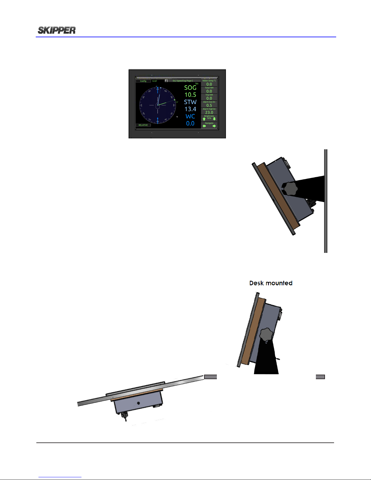
The operator unit is placed on the bridge.
Some standards require some operations of
the unit to be available from ‘standing position’.
These operations are available from the operator
unit and multi-repeaters if both input and output
are connected.
Dimensional drawings are found in Appendix 1.
Flush mount installation
Wall mount installation
Page 11
2018-05-28
Page 11 of 60
Installation DL2 Doppler Speed Log System
placemenT Of The elecTrOnic uniT
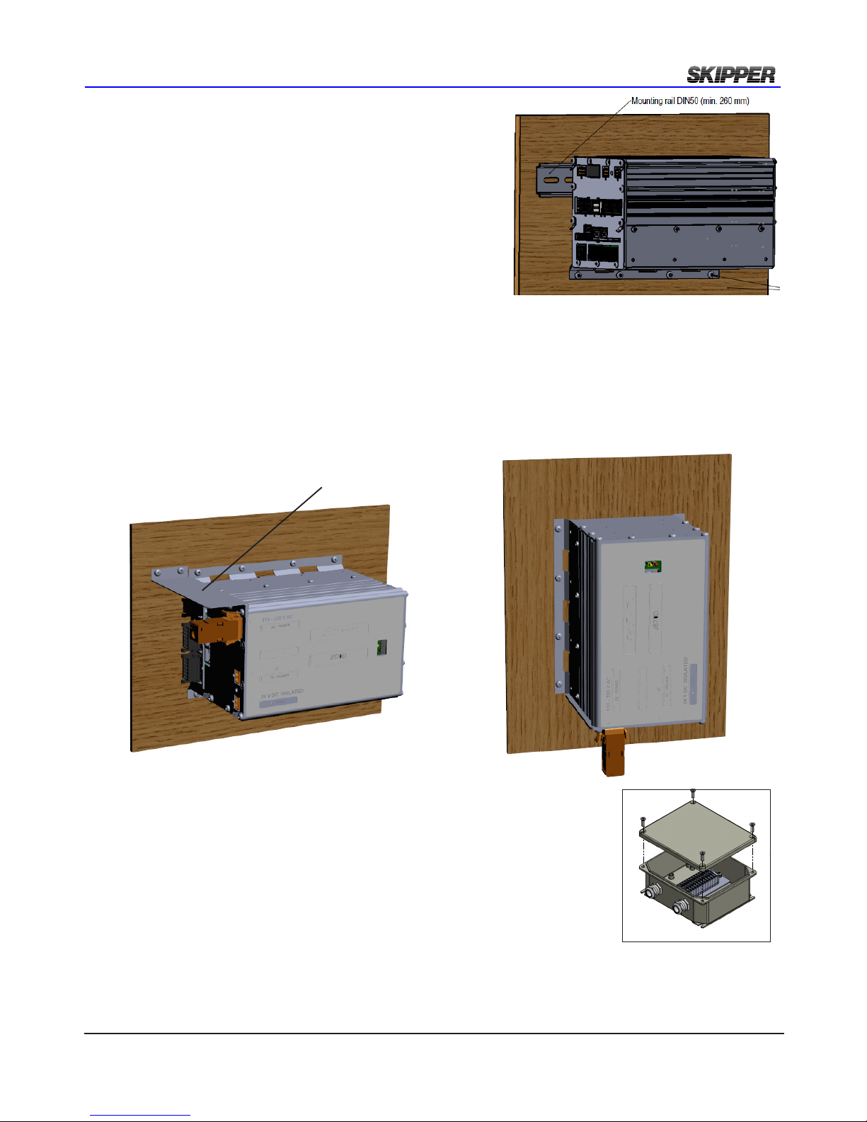
The electronic unit can be installed on a DIN rail or directly
screwed onto the wall.
All parts of the system are connected to the electronic unit.
There are no buttons (like ON/OFF) in the electronic unit.
Access is only required for service purpose.
Placement is typically in or near the bridge where the
interfaced systems are available, but no nearer than 0.5 m
to the GYRO heading sensor.
placemenT Of The elecTrOnic uniT ip22 apprOved
If IP22 is required for electronic unit then:
- Alternative 1
Horisontal installation. PCB’s vertical. IP22 Drip plate installed.
-Alternative 2
Vertical installation
Alternative 1
Alternative 2
Drip plate
placemenT Of repeaTers
Repeaters are typically installed on the overhead console and/or the bridge wings. These can be
routed using NMEA signals. These require a local +24 V DC supply.
E
B
A
8
7
6
D
C
placemenT Of Jb12 JuncTiOn bOx
The junction box JB12 is an option for connecting sensor cable to a yard
supplied extension cable (See chapter 3).
It is placed in a dry place within reach of the 40m sensor cable.
Page 12
Page 12 of 60
2018-05-28
Installation DL2 Doppler Speed Log System
placemenT Of The sea valve
Mounting instructions for the sea valve is available from the SKIPPER web site in separate manual
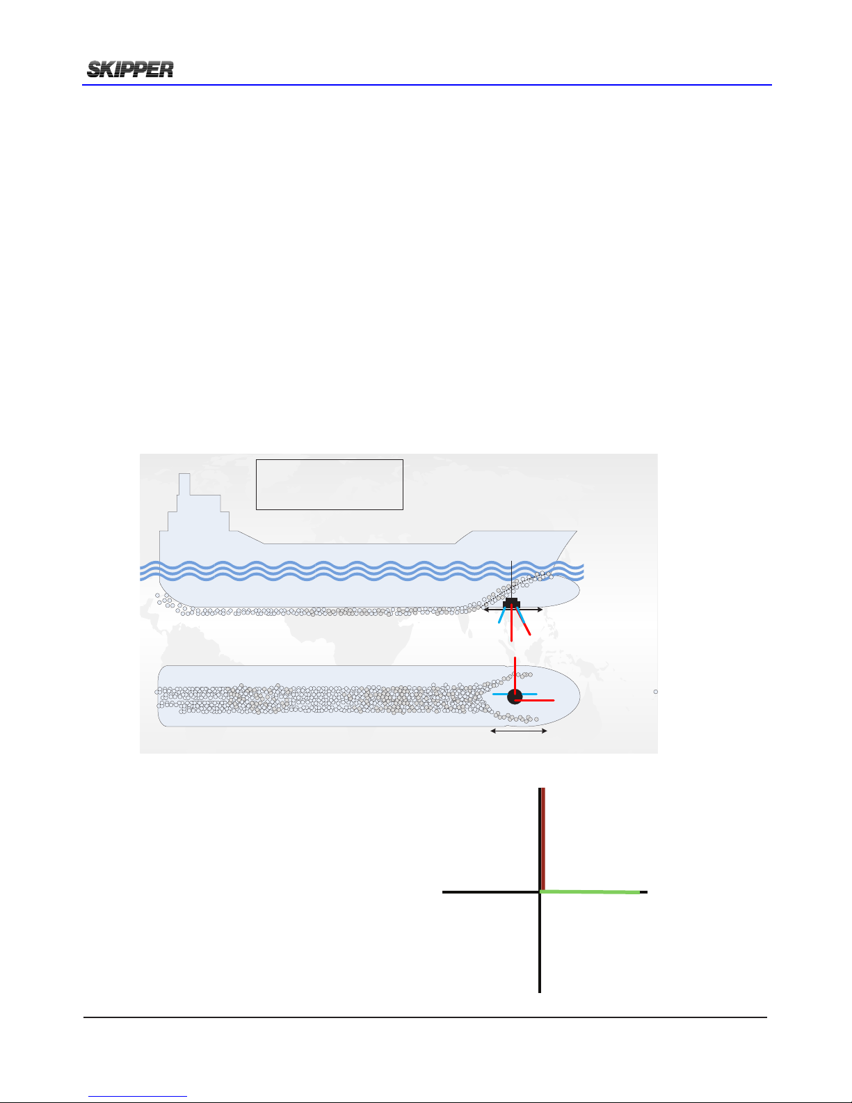
depending on the chosen type. When placing the speed log sensor, consider the following moments:
• Free sight to the bottom (it should be possible to draw a cone of +-45 degrees from the
sensor to the bottom).
• The active face of speed sensor must be in parallel to the horizontal line, max offset +-1°.
• Do not mount transducers aft of bow thruster, propeller outlets or aft of other hull
installations (such as outlets, vents or other protruding details) that may create aeration or
turbulence.
• It is necessary to select a part of the hull that is submerged and free from turbulence and
aeration under all load and speed conditions, and to avoid positions where air is trapped in
heavy weather.
• If a at, horizontal section is not available for transducer tting, the shipyard must construct
a suitable bed. Welding seams in this area and forward should be smoothed and rounded
off in order not to create turbulence or aeration and maintain a laminar waterow at all
speed ranges of the vessel.
• Select an area that is acoustically quiet. The system operates at frequencies between 270
kHz and 284 kHz.
There are 2 channels in DL2.
The acoustic signal is sent in
a 30deg angle in forward and starboard
directions.
In addition a tilt sensor is used to
compensate for vessel movement.
FWD
PORT
STRB
AFT
DL2
Longitudal speed
channel
DL2
Transversal speed
Channel
A
Bubbles
Sensor installation
A
Bubbles
Side view
Bottom view
Sensor placed
fore
Water relative speed is measured at a depth
between 0.3 and 3 m below transducer.
(DL1)
2 axis Water relative speed is measured at a
depth between 0.3 and 3 m below
transducer. (DL2)
Bottom track is measured down to 150m
depth
Page 13
2018-05-28
Page 13 of 60
Installation DL2 Doppler Speed Log System
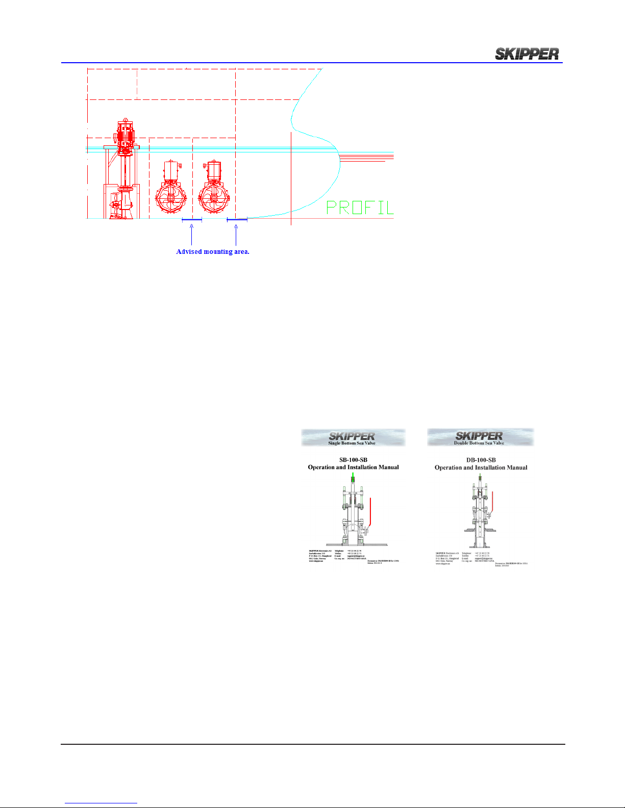
The generally best placement on larger vessels is in the front region of the vessel just behind the
bulbous bow (see g above). This area is generally designed such that the bubbles are pushed to
either side of the bulb, leaving a clear area under the bulb and just behind. The sensor is installed in
a sea valve in order to service the sensor (clean or replace) without docking the vessel.
It is recommended (but not required) to install the sea valve in a dry area, like a bow thruster room.
This will enable easy cable access to junction box and additionally increase the lifetime of the sea
valve.
The sensor DL2 is installed into sea valve
100mm for single bottom SB-100-SB or
double bottom DB-100-SB.
Please see sea valve manual for installation
procedure.
Manuals available as downloads from
www.skipper.no
The sensor includes 40m moulded in cable.
The cable is 11 mm in outer diameter with a
bending radius of 56 mm. The cable can be
cut or extended if required
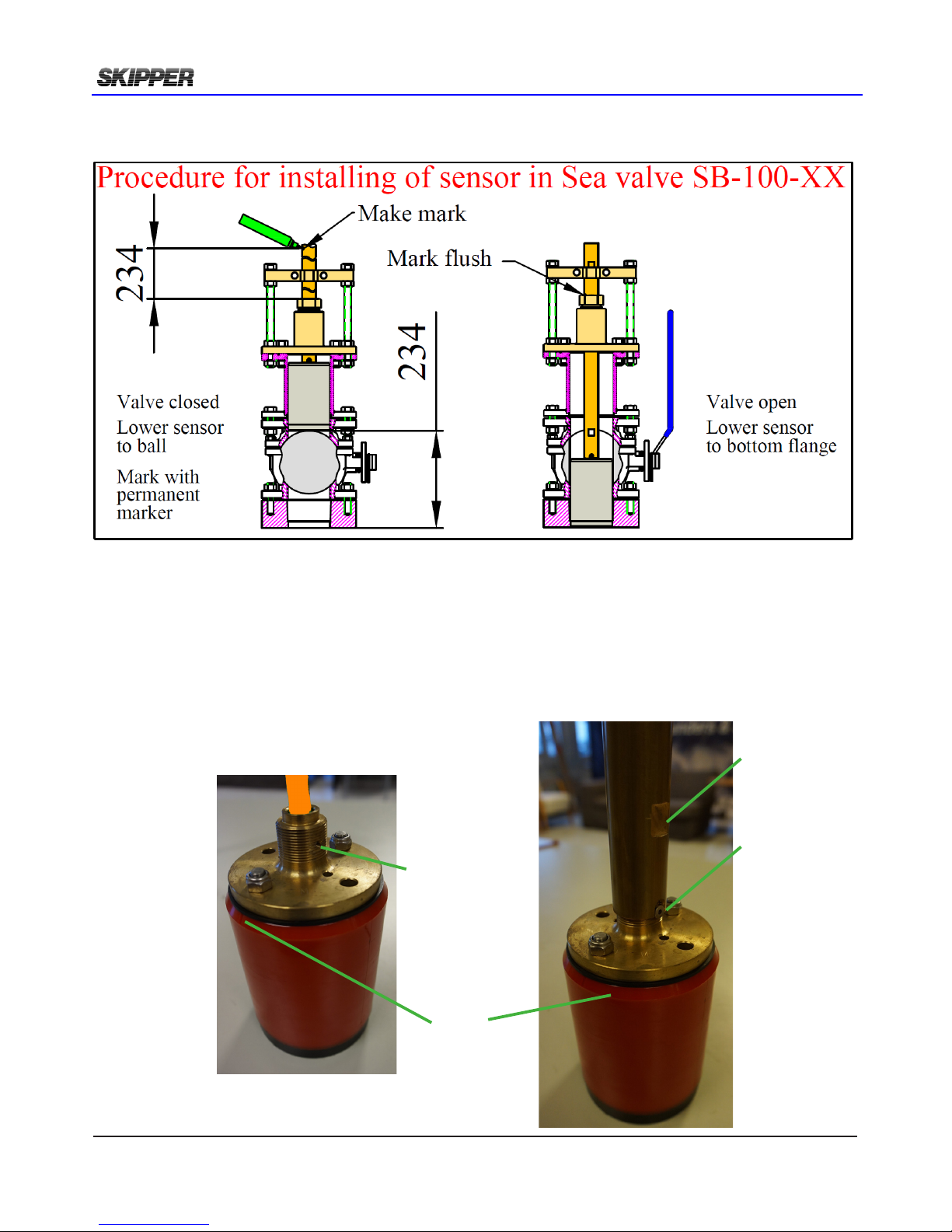
placemenT Of The sensOr in sea valve
NOTE
During physical installation of sensor into sea valve please make special care of the following points:
• Sensor to be lowered completly into bottom ange making sensor head ush with outer hull.
• Sensor forward direction to be aligned +/-10deg. (Fine adjust by software in calibration page)
• Clamping unit nuts and nut M50 to be tighten to secure sensor position.
Page 14
Page 14 of 60
2018-05-28
Installation DL2 Doppler Speed Log System
Sensor forward direction.
It is important to align sensor forward direction.
Pictures showing forward direction alignment in sea valve SB-100-SB.
Sensor lowered ush with outer hull.
Pictures showing lowering procedure in sea valve SB-100-SB.
Threaded hole
Port side
Forward
position mark
in moulding
Screw M4
In threaded
hole
Port side
Flat area
Port side
Page 15
2018-05-28
Page 15 of 60
Installation DL2 Doppler Speed Log System
A at object points fore/aft.
The at side should be on the port side.
DB-2039
Nut M28
DB-2037
Washer (2x)
Gasket
DB-2038
Final Assembly
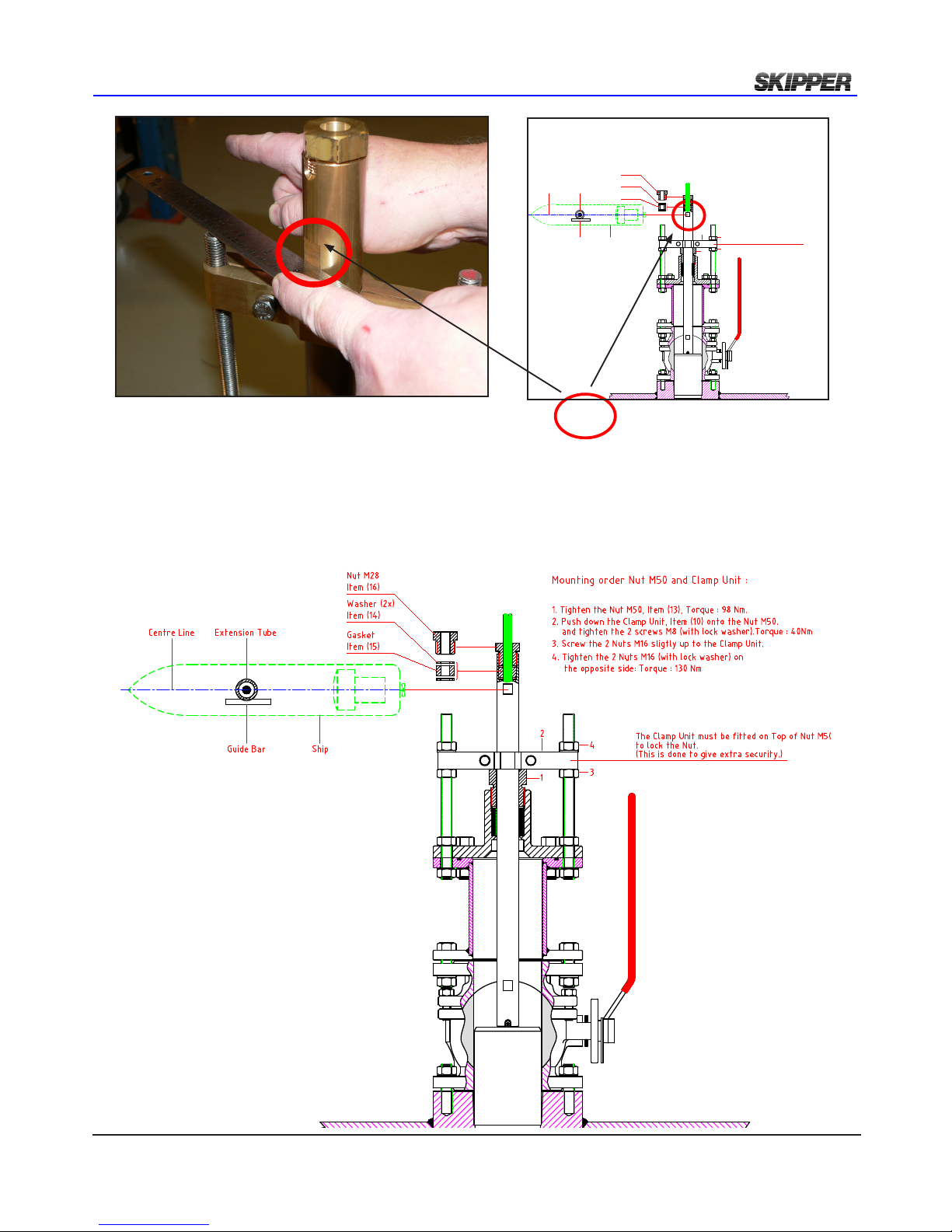
1. Tighten the Nut M50 (DB-2036). Torque : 98 Nm
2. Push down the Clamp Unit (DB-2033) onto the Nut M50.
and tighten the 2 screws M8 (with lock washer).Torque : 40Nm
3. Screw the 2 Nuts M16 sligtly up to the Clamp Unit.
4. Tighten the 2 Nuts M16 (with lock washer) on
1
2
3
4
Mounting order Nut M50 and Clamp Unit :
the opposite side: Torque : 98 Nm
The Clamp Unit must be fitted on Top of Nut M50
to lock the Nut.
(This is done to give extra security.)
Extention TubeCente Line
Guide Bar Ship
Secure sensor by tightening clamping unit and nut M50
Page 16
Page 16 of 60
2018-05-28
Installation DL2 Doppler Speed Log System
CHAPTER 3: WIRING
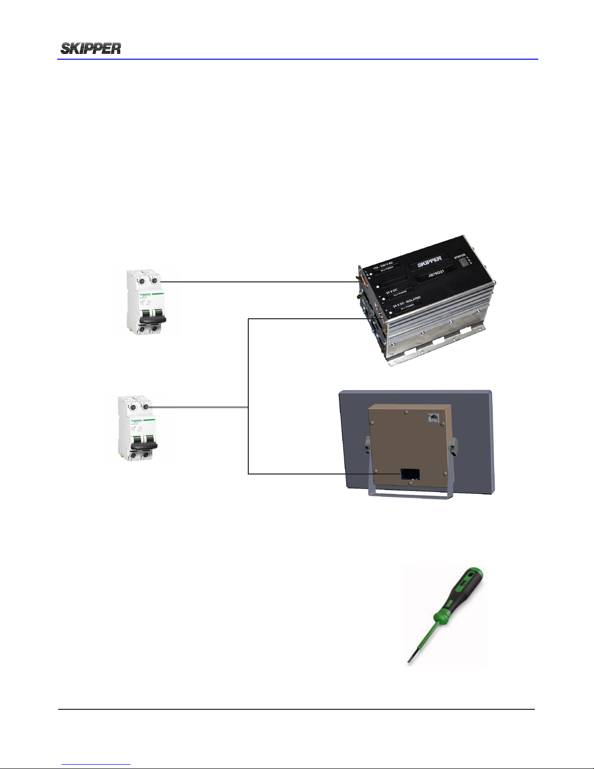
The JB70D2-SA does not contain a physical switch (only software) and should be connected to a
circuit breaker for removal of power.
Power may be nominal 24V DC (No more than 32V DC) and/or 115-220V AC. Max 60W typical 15W.
The AC input is an optional back up for JB70D2-SA only. The operator unit CU-M001-SA requires a
24V DC power supply.
There are no input fuse on the CU-M001-SA or JB70D2-SA.
The power input should be including a fuse rated for 100% - 200% of max power installed components.
Example: A 24V DC to power both CU-M001-SA and JB70D2-SA should have a 3A slow blow fuse.
clamping The cables
Cables should be connected to WAGO connector, leaving
approximately 3 cm of tail. They should be stripped with 6-7 mm of
metal showing and these should be connected as in the diagram
above. A small screwdriver with blade size approx 3.5 mm can be
used. WAGO part no 210-719 is ideal for this use.
Outer shields should be collected and grounded in a ground stud on
the edge of the cabinet. The outer insulation should be cable tied to
the plastic handle of the connector, and securely anchored nearby.
The plugs when retted, must be installed such that their clips are
fully in the up position.
220V AC. 0,5A
115V AC. 1A
24V DC. 3A
Page 17
2018-05-28
Page 17 of 60
Installation DL2 Doppler Speed Log System
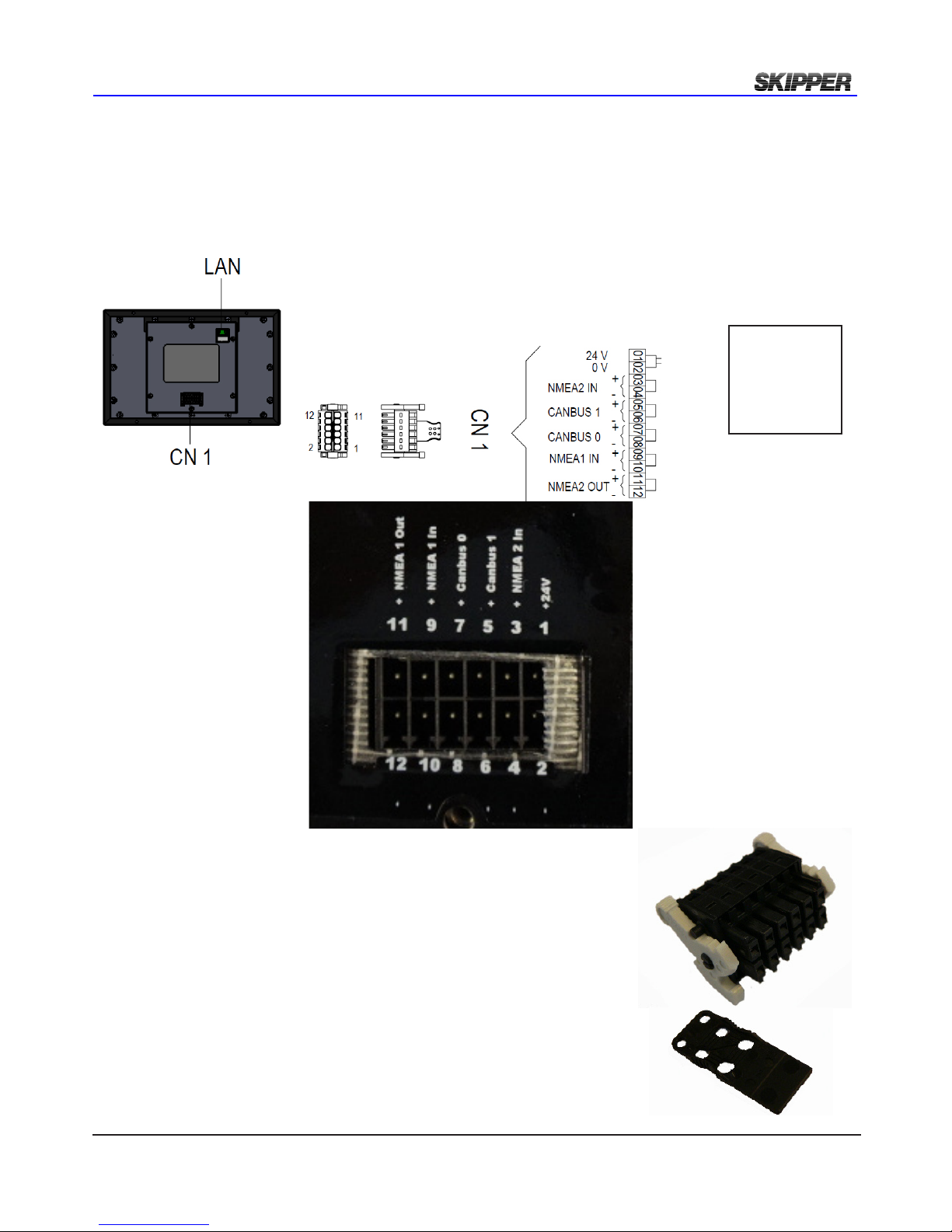
cu-m001-sa OperaTOr uniT wiring
The operator unit has 2 connectors.
1 LAN connector for communication with Electronic unit.
2: WAGO connector CN1 for 24V power. Max 10W, Typical 6W.
Items supplied with CU-M001
1 x ZZN-01120.
Connector Female w/ejectors 6x2 pole, black. (CN 1)
1 x ZZN-01123. Strain relief plate, 6x2 pole, width 11 mm. (CN 1)
Note:
NMEA and
CANBUS are
options not yet
implemented
Page 18
Page 18 of 60
2018-05-28
Installation DL2 Doppler Speed Log System
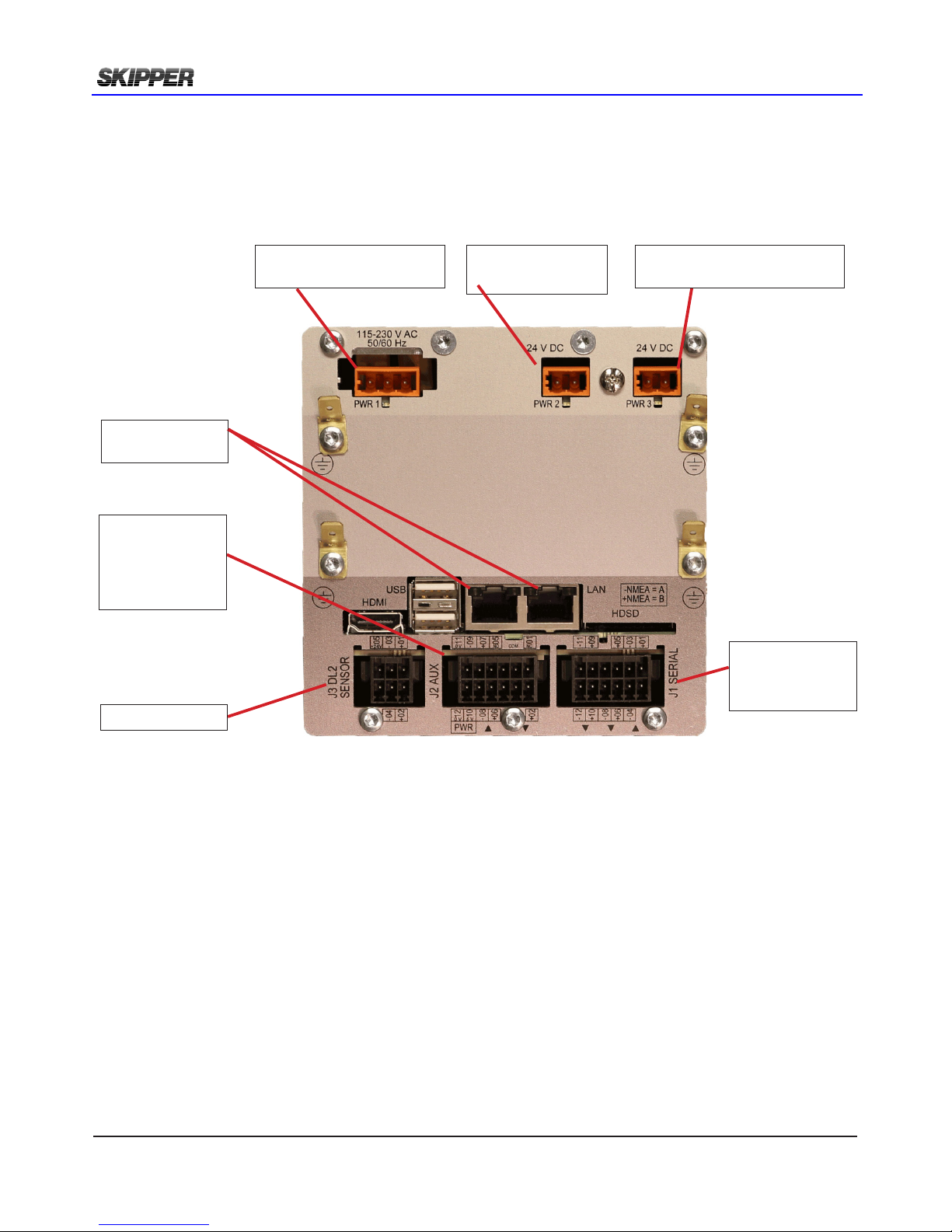
Jb70d2-sa elecTrOnic uniT wiring
The JB70D2-SA is connected with Operator unit CU-M001 with the LAN connectors. The second
LAN connector may be used for set up/ service purpose.
PWR 3
Not in use on DL2
Power in PWR 2
24V DC
Power in PWR1
115-220V AC
Sensor J3
NMEA J1
2 x NMEA In
4 x NMEA Out
AUX/Alarm J2
Alarm relay
1 x AUX In
2 x AUX Out
2 x LAN
Page 19
2018-05-28
Page 19 of 60
Installation DL2 Doppler Speed Log System
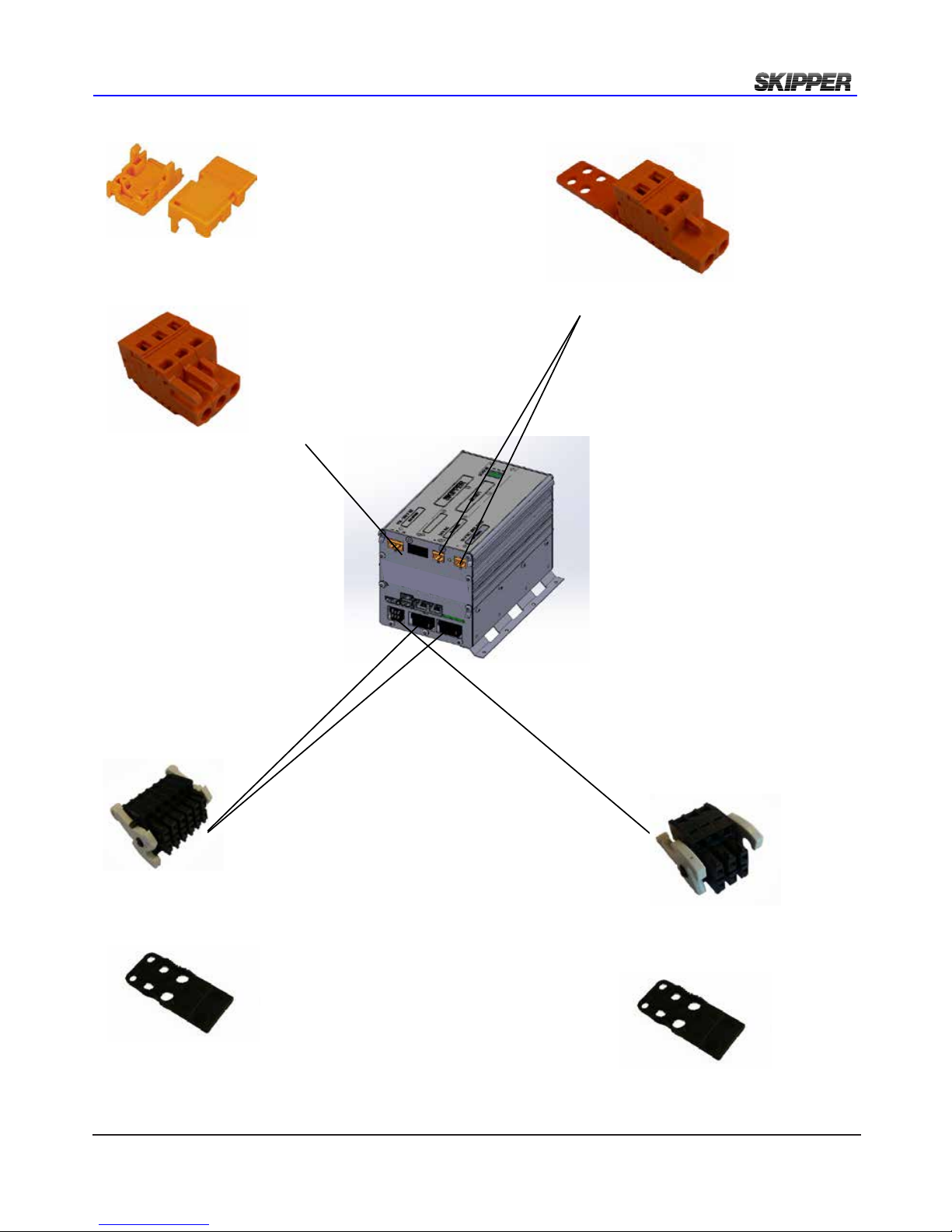
ZZN-01126 Relief Housing,
3 pole snap-on.
WAGO: 232-633
ZZN-01125 Plug, Female 3
pole,231-303 026
ZZN-01124 Plug, Female 2
pole, 231-302_032-000
ZZN-01123 Strain relief
plate, 6x2 pole, width 11 mm
WAGO 713-126
ZZN-01120 Connector Female w ejectors 6x2 pole, black
WAGO 713-1106/037-000
ZZN-01123 Strain relief
plate, 6x2 pole, width 11 mm
WAGO 713-126
ZZN-01130 Connector, Female w/ejectors 3x2 pole, black
WAGO 713-1103/037-000
cOnnecTOrs supplied wiTh Jb70d2
Page 20
Page 20 of 60
2018-05-28
Installation DL2 Doppler Speed Log System
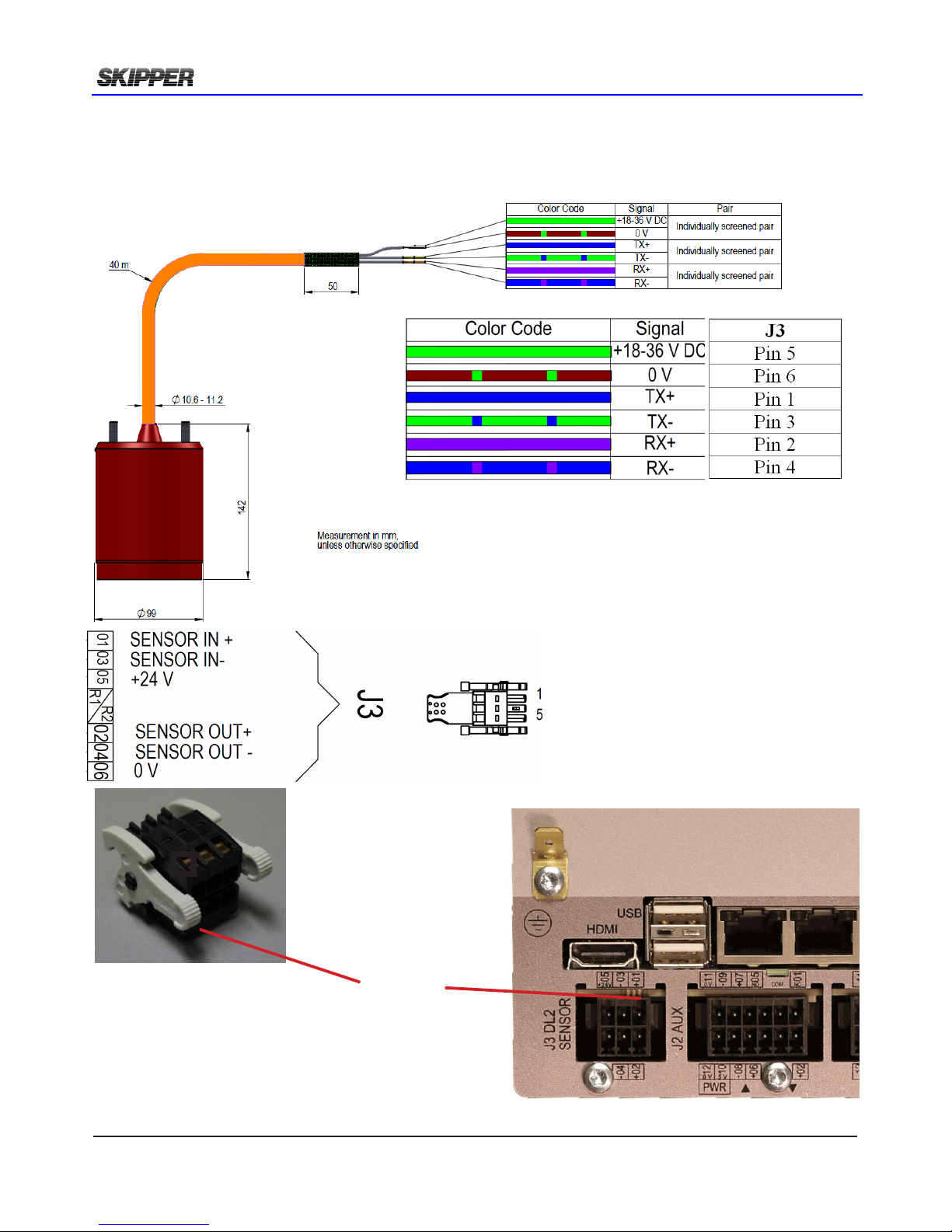
sensOr cOnnecTiOn J3
The sensor is connected to JB70D2-SA Connector J3. 6 pin WAGO connector.
The cable screen is connected to screen on sensor side and does not need to be grounded at
JB70D2-SA side, if the system has instability problems grounding at the JB70 unit may help. .
J3 Pin1
1
6
5
4
3
2
Page 21
2018-05-28
Page 21 of 60
Installation DL2 Doppler Speed Log System
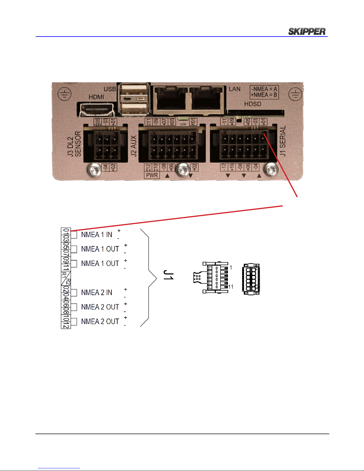
nmea cOnnecTiOn J1
The DL2 has standard 2 NMEA Inputs and 2 Outputs.
Each output is dual and makes total of 4 outputs.
J1 Pin1
If high speed prototcols are to be used (IEC61162-2) the communication common (COM) can be connected to pins 11 or 12 of J2
Page 22
Page 22 of 60
2018-05-28
Installation DL2 Doppler Speed Log System
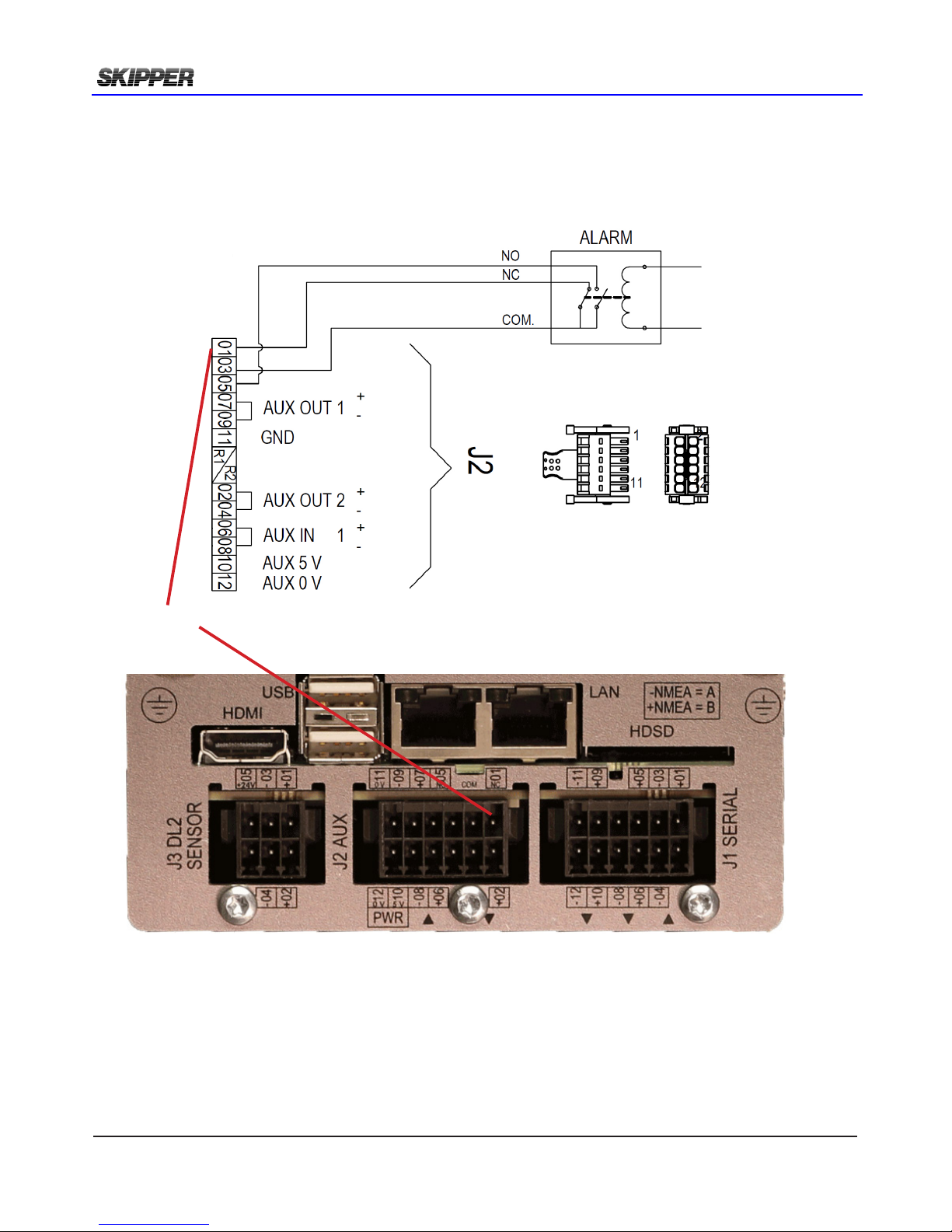
aux/alarm cOnnecTiOn J2
The DL2 has standard
Alarm relé
1 x Aux In. (default set as “Alarm reset”)
2 x Aux Out.
addiTiOnal nmea, aux and analOg OuT
An optional Multi Extension PCB is required for additional NMEA, additional Aux or analog output.
See Appendix 3.
J2 Pin1
Page 23
2018-05-28
Page 23 of 60
Installation DL2 Doppler Speed Log System
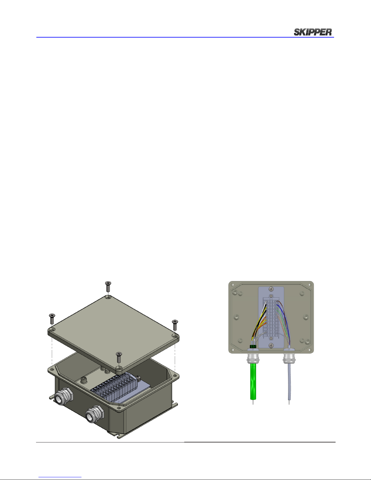
The JuncTiOn bOx (Jb12)/splice
The JB12 Junction box may be used as a terminal between sensor cable and an extension cable.
Dimensional drawing see Appendix 1.
All individual screens of sensor cable to be connected to the outer screen of the CAT7 extension
cable.
Do not ground screens to JB12 chassis.
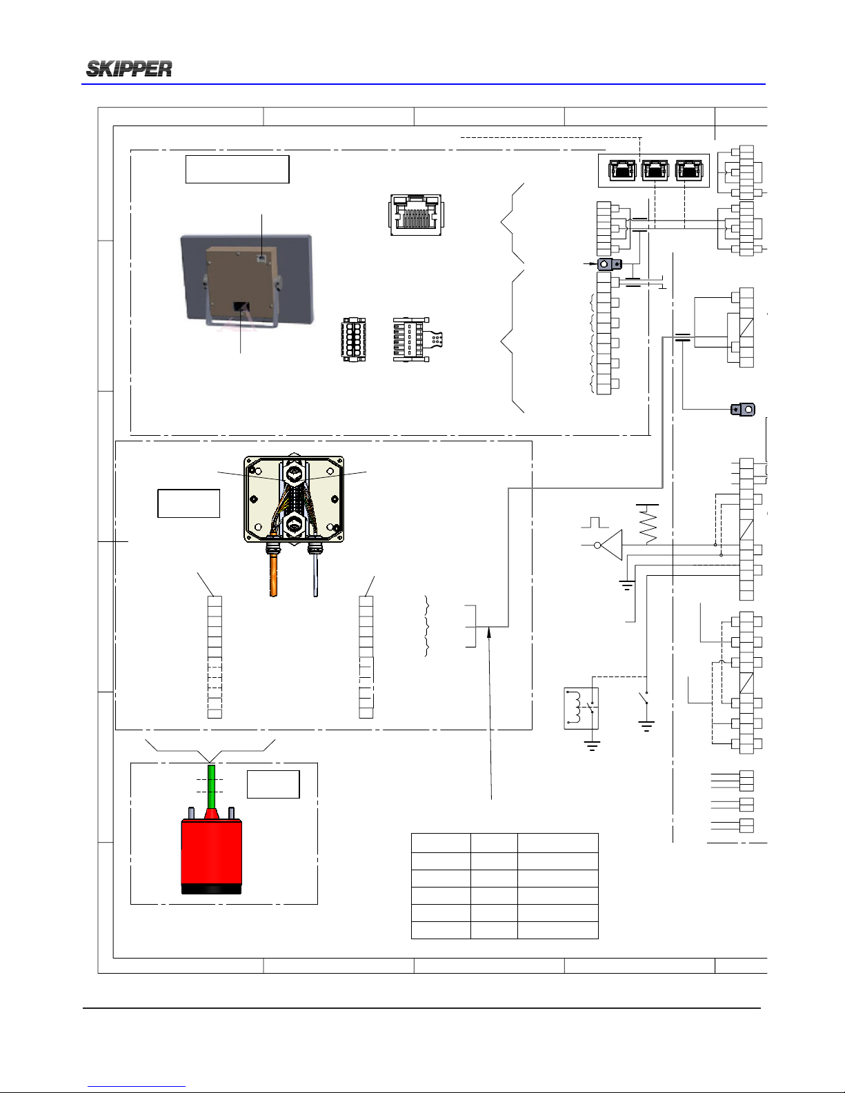
yard supplied exTensiOn cable frOm sensOr TO Jb70 elecTrOnic uniT.
Any screened 3 or 4 twisted pair cable can be used as long as the loop resistance (measured by
twisting the pair together at one end and measuring the resistance) is less than 8.6 ohms (worst
case).
Example1:
What kind of cable do I need for 300m distance from sensor to Electronic unit?
300m cable (0.3km). Loop length 0.3*2 =0.6km. 8.6/0.6=14.3 Ohms/km
Use a cable with maximum 60 Ohm conductor DC resistance per km.
AWG15 / 1.5mms has resistance of 10.4 ohm /km
Example2
I have a CAT7 cable. Spec says 70 Ohm conductor DC resistance per km. How long distance from
sensor to Electronic unit can I use this cable?
8.6/70=0.122km. 0.122km/2=60.1m maximum length.
Color Code
Signal
Screen
Color Code
Pair
Screen
White
+18-36 V DC
Individually
screened pair
Brown / White (blue)
Pair
Common screen
Black
0 V
Blue (brown) / Blue (white)
Pair
Yellow
TX+
Individually
screened pair
White (green)
Pair
Black
TX-
Green (white)
White
RX+
Individually
screened pair
White (orange)
Pair
Orange
RX-
Orange (white)
Yellow
Aux+
Individually
screened pair
N/A
Pair
Orange
Aux-
N/A
To be grounded
together and
passed into the
outer screen of the
Cat5e cable
Page 24
Page 24 of 60
2018-05-28
Installation DL2 Doppler Speed Log System
GRD STUD
PIN 1
PIN 13
LAN
CN 1
1
11
12
2
LAN
CN 1
CU-M001
JB12
PIN 1
DL2S
TO INS. IEC61162-45O
*
CANBUS 0
ALARM
GPS / BAM
(AUX)
(DL2)
(DL2)
+
-
+
-
+
-
+
-
+
-
+
-
+
-
+
-
+
-
+
-
+
-
+
-
+
-
+
-
NMEA 2 OUT
NMEA 2 OUT
NMEA 2 IN
NMEA 1 OUT
NMEA 1 OUT
82 71 5 63 4
0703 10060205 09
R1
R2
120801 0411
0 V
24 V
PULSE
LEVEL
OUTPUT
ALARM +
0 V
+24 V
0 V
+24 V
N
L
G
+24 V
0 V
0 V
+24 V
N
G
L
5 -24V
5 -24V
NMEA1 OUT
SWITCH
BAM / VDR
INS/ECDIS
RADAR
OR BETTER
RESET -
CAT 5e
NMEA1 IN
CANBUS 1
NMEA2 IN
0 V
06010203 11
75
04 1210
84 63
07
1
24 V
05 0908
2
7 84 5 631 2
R1
R2
0501 03
060204
212132
NMEA 1 IN
1210080604021109070503
DC
DC
AC
AUX 0 V
AUX IN 1
AUX OUT 2
AUX OUT 1
0 V
SENSOR OUT -
SENSOR OUT+
+24 V
SENSOR IN-
SENSOR IN +
AUX 5 V
R2
R1
1
01
COM.
NC
NO
J1J2
POWER
LAN
J3
GND
GREEN
BROWN / GREEN
BLUE
GREEN / BLUE
VIOLET
BLUE / VIOLET
PIN 13
SENSOR IN+
SENSOR IN-
13
14
15
16
17
1813
+24V SENSOR
0V SENSOR
SENSOR OUT+
SENSOR OUT-
01
02
03
04
05
06
GREEN
ORANGE
BROWN
GREEN
BROWN
ORANGE
+24V SENSOR
SENSOR OUT+
SENSOR IN+
SENSOR IN-
SENSOR OUT-
0V SENSOR
07
GROUND
BLUE / VIOLET
GROUND
**
**
**
19
GROUND
DO NOT CONNECT
GROUND TO HOUSING
3 TSP (twisted shielded pairs)
AWG
mm2
Max length m
23 /CAT6
0,26
65
22 /CAT7
0,33
73
20
0,5
133
18
0,823
209
15
1,5
423
E
F
C
1
2
3
4
B
A
3
2
1
5
4
Electronics AS
D
Checked by
2016.11.02 ST
Endret verdier i
AWGtable
CN
XXX
Designed by - date
XXX
A.Matre 2014.06.03
Approved by - date
Page 25
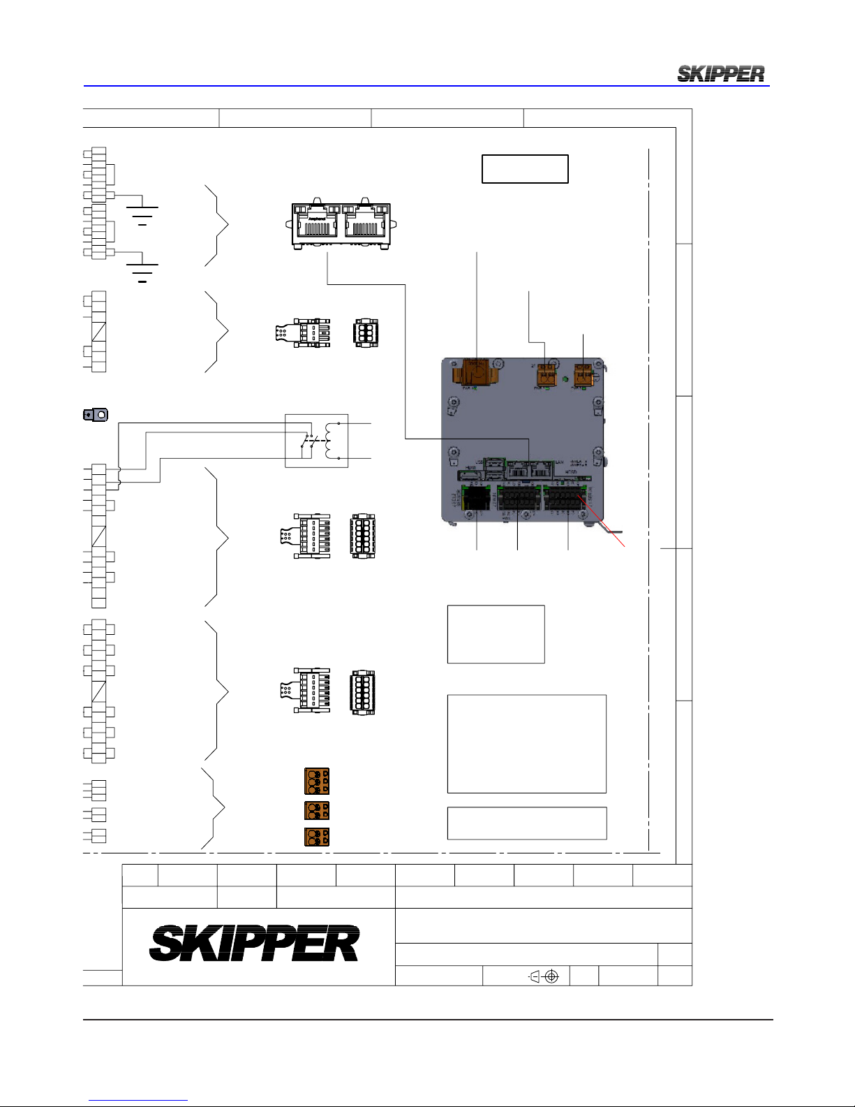
2018-05-28
Page 25 of 60
Installation DL2 Doppler Speed Log System
(AUX)
(DL2)
(DL2)
+
-
+
-
+
-
+
-
+
-
+
-
+
-
+
-
+
-
NMEA 2 OUT
NMEA 2 OUT
NMEA 2 IN
NMEA 1 OUT
NMEA 1 OUT
82 71 5 63 4
0703 10060205 09
R1
R2
120801 0411
+24 V
0 V
0 V
+24 V
N
G
L
7 84 5 631 2
R1
R2
0501 03
060204
212132
NMEA 1 IN
1210080604021109070503
DC
DC
AC
AUX 0 V
AUX IN 1
AUX OUT 2
AUX OUT 1
0 V
SENSOR OUT -
SENSOR OUT+
+24 V
SENSOR IN-
SENSOR IN +
AUX 5 V
R2
R1
1
01
*
AUX OUTPUT
ADD RESISTOR
TO GIVE MAX 100 mA
24 V = 220 Ohm
5 V = 50 Ohm
NMEA - = A
NMEA + = B
COM.
NC
NO
J3 J2 J1
J1J2
2
6
1
5
2
11
12
1
DC(24V)
Power for DL1
DC (24V)
Power for DL2
AC (115V-230V)
Power for DL2
JB70D2
12
2
11
1
POWER
LAN
ALARM
J3
PIN 1
GND
OPTIONAL COLORS
**
5
C
D
6
7
8
A
B
Electronics AS
E
ISO2768m
X:X
Gen. tolerance
Eur. projection
XXX
Material
2016.11.02
Checked by
2016.11.02 ST
Endret verdier i
AWGtable
CN
Drwg. no.
Name
XXX
Edition date
Sheet
01
Revision
CD-2037
Scale
Wiring diagram for DL2 Multi
1 of 1
Designed by - date
XXX
A.Matre 2014.06.03
Approved by - date
Page 26
Page 26 of 60
2018-05-28
Installation DL2 Doppler Speed Log System
CHAPTER 4: SETUP PROCEDURE
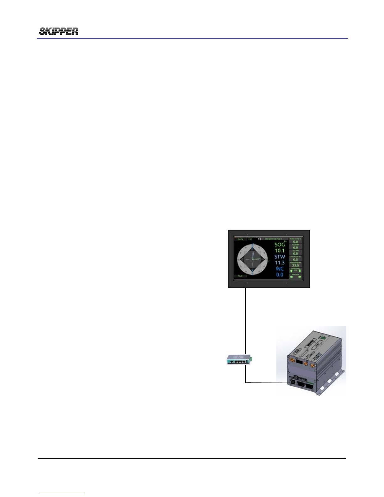
Setup of communication JB70D2-SA to CU-M001-SA
The communication between operator unit and Electronic unit is following IEC61162-450 lightweight
ethernet standard.
This standard allows the network to be used for the distribution and control of sensor systems such
as the DL2. These communicate using proprietary NMEA type messages on this multicast (UDP)
system. The system will exert a maximum load on the network of 20 kB/s (kilobyte per second), and
will tolerate a data trafc up to 20Mbit/s (Megabit per second)
An advantage of this method of communicating is that it becomes simple to have more than 1
display unit on the same system. Instead of (or as well as) repeaters, the user can have as many
control units as they wish. These are activated by pairing the units to the electronic unit. In the case
of INS bridges, the main bridge conning unit can be used as a control unit as well or instead of the
screen (with approval).
The following prameters must be set on both units before communication is established:
• IP adress
• SFI
• Paired SFI (only for Operator unit CU-M001-SA)
• Group
CU-M001-SA Operator Unit for DL2
LAN cable. CAT6. Max. 100m
JB70D2-SA Electronic Unit for DL2
LAN switch
(option)
IP Address: The IP address of the system should not clash
with any other system within the network. Regulations
state that the IP address range. During setup, it may be
necessary to change the IP to t into your local network.
SFI (System Function ID): Each device has its own
identier (SFI) and the systems can then identify who they
are and who they are talking to. These should be unique
within a vessel.
Paired SFI: Each Operator unit CU-M001-SA device
needs to know which system it is part of. By entering the
SFI of the JB70D2-SA the system pairs itself.
It is possible to have multiple screens to a single JB70D2SA unit. All screens will work in parallel.
Group: There are 16 groups available for the system to
be part of. It is important that the group is the same on all
communicating devices.
NOTE: The following procedure will take you through the setup using the operator unit CU-M001.
It is important to change the JB70D2-SA group before the CU-M001-SA group otherwise you will
loose connection
The setting of IP adress, SFI, Paired SFI and Group on JB70D2-SA is also accessible from SKIPPER
service software by connecting a PC to the second LAN port or via a LAN switch.
SKIPPER service software is available in dowload folder on www.skipper.no
Page 27
2018-05-28
Page 27 of 60
Installation DL2 Doppler Speed Log System
cOnfig
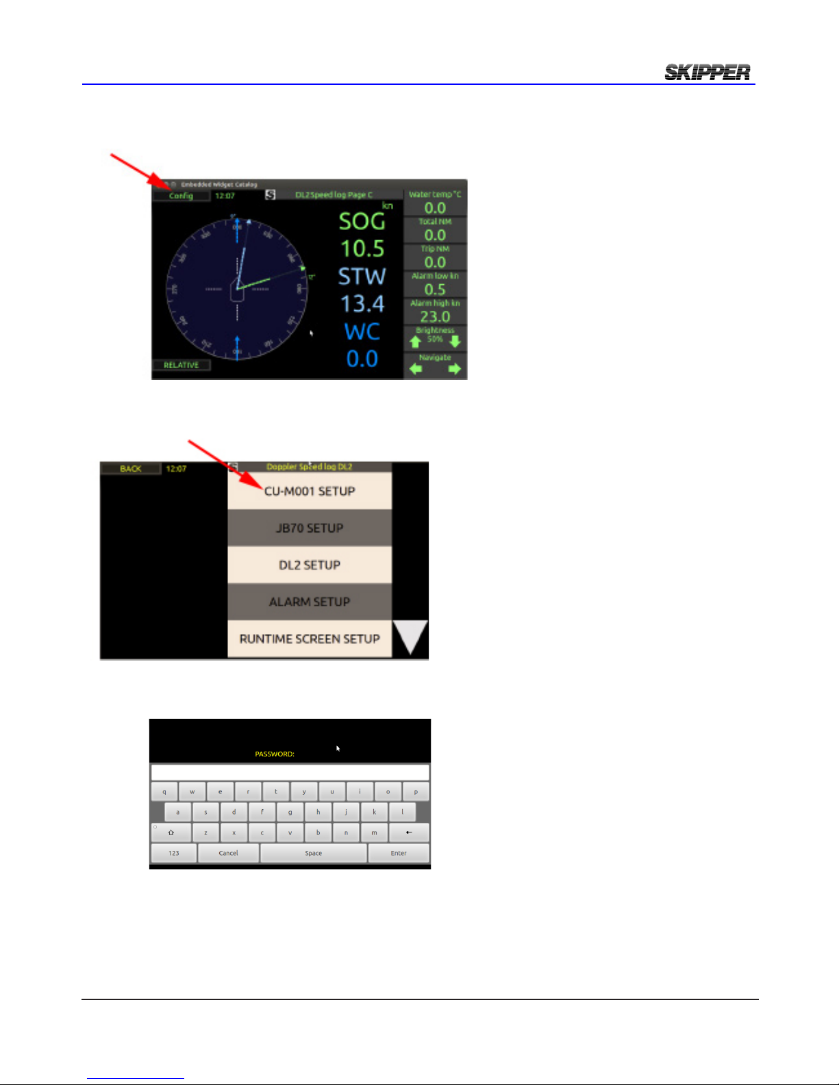
Setup pages are accessed by pressing “CONFIG”
First, the Operator unit CU-M001-SA must be connected to the main Electronic Unit JB70D2-SA.
To do this enter the “CU-M001 SETUP” page.
To enter and adjust these screens a password is required. The password for all units is ‘service’.
The password will be remebered for 1 hour, or until reboot of the system.
Page 28
Page 28 of 60
2018-05-28
Installation DL2 Doppler Speed Log System
cu-m001 seTup
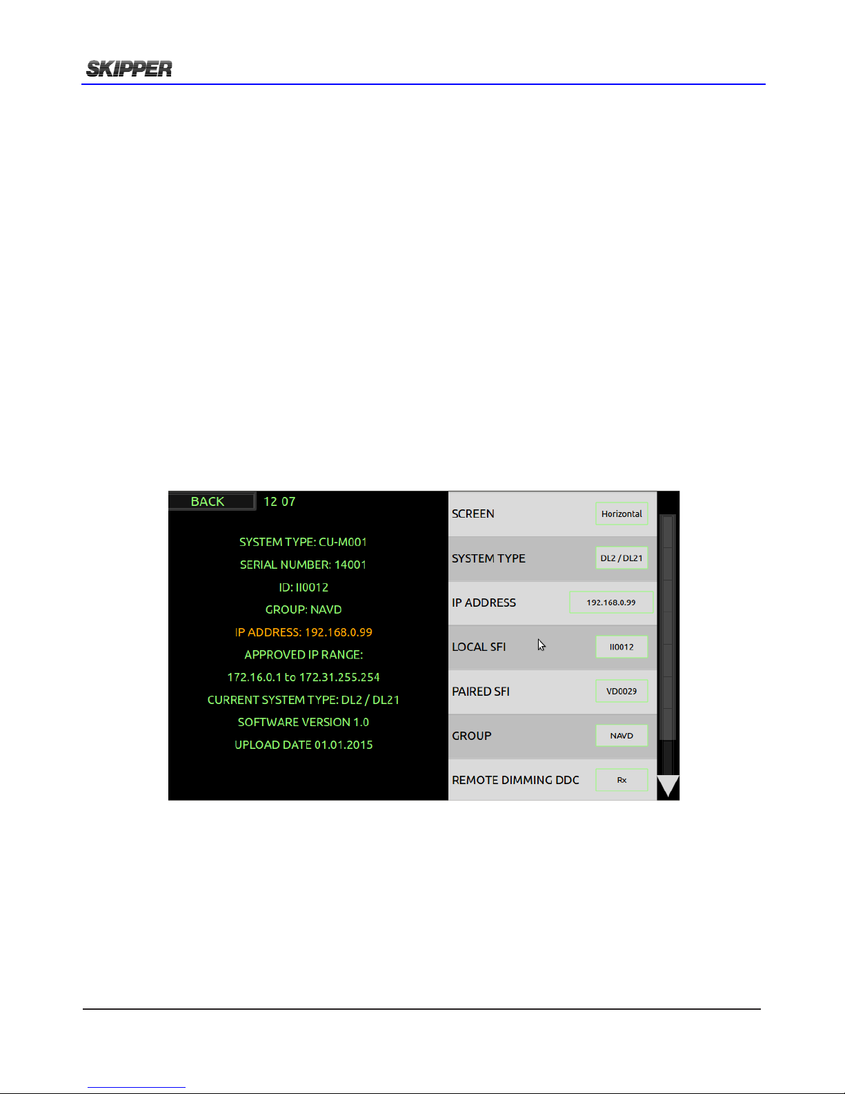
On starting the display CU-M001 rst time it will try pair up with a JB70D2-SA.
Default settings:
Screen: Horisontal (no vertical available)
System type: DL2/DL21
IP Address: 172.16.1.102
SFI (System Function ID): II0102
Paired SFI: VD101(default SFI of JB70D2-SA)
Group:NAVD.
Dimming: Rx
NOTE:
If connected to LAN network please make sure IP adresses, SFIs and Group is approved by local
administrator.
If 2 x DL2/DL21 systems are to be installed on same LAN then IP adress SFI and paired SFI have
to be changed on (at least) one of the systems to avoid conict of settings.
If default values have to be replaced then please change IP adress of JB70D2 before changing on
CU-M001.
Remote dimming DDC
Off
The screen can be dimmed on screen.
Rx
The screen can be dimmed on screen or using a remote DDC message. The system can be made
to accept remote dimming from the local input or the JB70 input.
Tx
The screen can be dimmed on screen or using a remote DDC message. The system can be made
to accept remote dimming from the local input or the JB70 input.
It can also be made to send a DDC message when the dimming level is changed.
Page 29
2018-05-28
Page 29 of 60
Installation DL2 Doppler Speed Log System
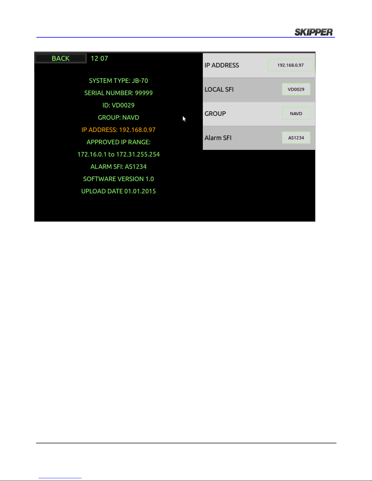
Jb70d2 seTup
Default settings:
IP Address: 172.16.1.101
SFI (System Function ID): VD0101
Group:NAVD.
Alarm SFI: AS0101
When on this setup page, the user is setting parameters on the remote device. It is therefore important
that the devices are properly connected before adjusting here. If the devices are not connected you
will see a system alarm on screen. Pressing this symbol will show which alarm is active.
This process can also be performed in a simpler way by using the Communications Application
avalable in the SKIPPER service software (available for download on the SKIPPER website.)
This App allows you to connect to the same network as the units and then perform a search. The
software will show you all the connected units, and you may then edit the IP adress, SFI and group
from the software. You may then enter the web pages for each individual unit.
Page 30
Page 30 of 60
2018-05-28
Installation DL2 Doppler Speed Log System
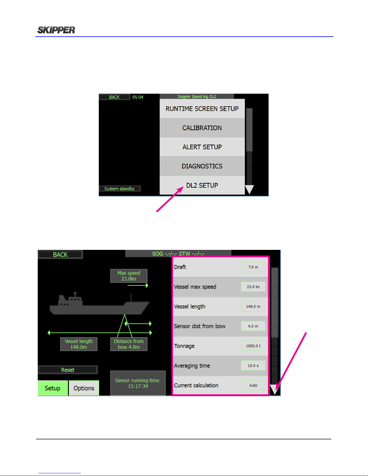
dl2 seTup
To help the system to calculate accurate a number of parameters should be setup for the specic
vessel it is installed into. These are entered in the DL2 setup menu.
DL2 setup is accessible from the “cong” menu.
Press “arrow”
to access more
buttons
Page 31
2018-05-28
Page 31 of 60
Installation DL2 Doppler Speed Log System
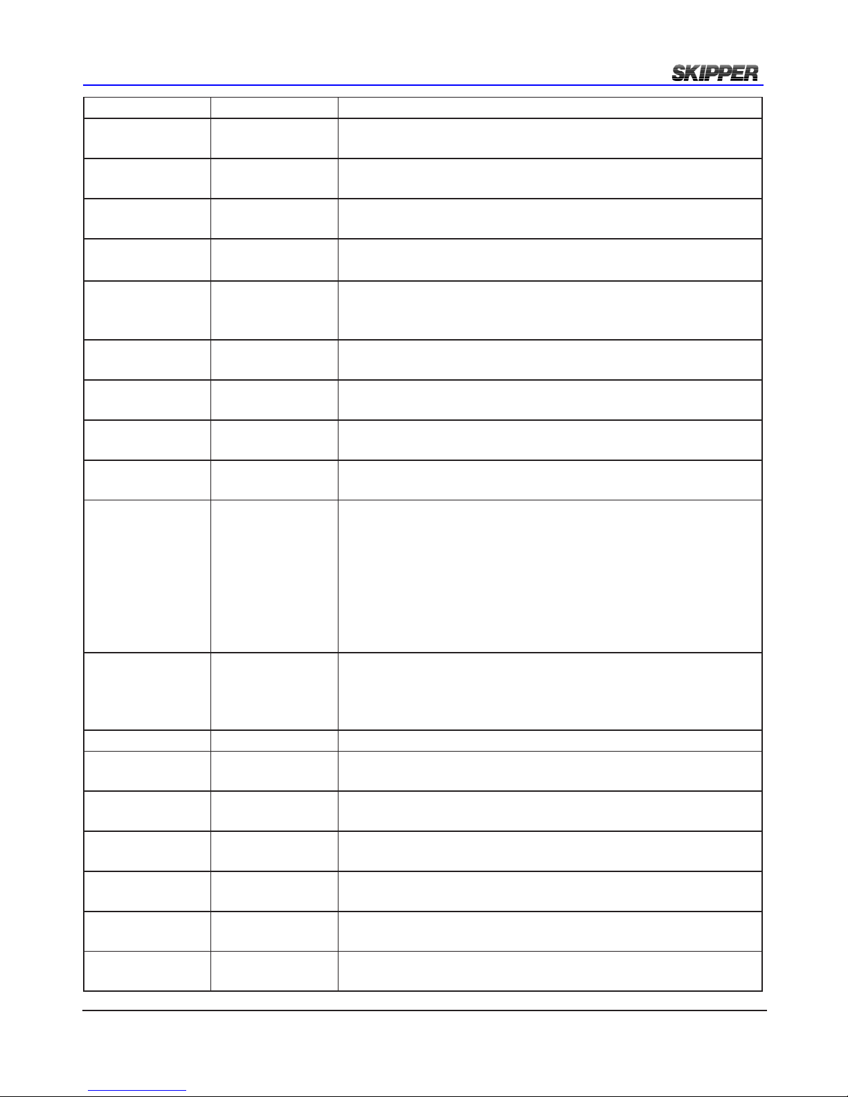
Button (default) options What it is used for
Draft (meters) feet fath-
oms
Used to make the depth value show from the surface and not from
the sensor.
Vessel Max Speed (knot) m/s mi/h Used to set the calibration parameters and to ensure data is rea-
sonable.
Vessel Length meters Used to calculate The Aft transversal speed
(ROT signal must be input for this)
Sensor distance
from Bow
meters Used to calculate The Aft transversal speed
(ROT signal must be input for this)
Tonnage tonnes Used to set correct averaging time. Larger vessels will have
slower speed changes and may use a higher averaging to calculate
the speed.
SOG Averaging
time
seconds Manuel set of averaging time for SOG at speeds over 6kn. This
setting will override settings from “Tonnage”
SOG low speed
averaging time
seconds Manuel set of averaging time for SOG at speeds under 6kn. This
setting will override settings from “Tonnage”
STW averaging
time
seconds Manuel set of averaging time for STW at speeds over 6kn. This
setting will override settings from “Tonnage”
STW low speed
averaging time
seconds Manuel set of averaging time for STW at speeds under 6kn. This
setting will override settings from “Tonnage”
Current
calculation
(AUTO)
Log-SOG,
GPS-SOG
AUTO
The “Water current” speed and direction are calculated from the
STW measurement and an SOG from the log and/or a GPS input.
In deep water,(depths>150m) SOG is not available from the log.
AUTO will automatically change from log to GPS when log bottom is lost.
Log-SOG will allways calculate “Water current” with SOG from
log.
GPS-SOG
GPS on lost bottom
(ON)/OFF If the water is too deep, the system cannot measure SOG. This
option will switch the value to GPS (on screen) with a small symbol to indicate where the data comes from.
The system will not send SOG data on its outputs in this case.
Vessel image 1-5 The image of a vessel can be changed to various vessel types.
SOG Shallow
ping length
1-(2)-4-8msec. Default 2msec.
May be set to 1msec for better shallow water
SOG Deep ping
length
1-2-4-(8)msec. Default 8ms for deeper bottom tracking
SOG Shallow
power
Low-Medium(High)
Default High. Power level of SOG signal in shallow water
DL1/DL2 synch OFF / (ON) In DL2 the systems can be made to ping simulataniously to pre-
vent acoustic cross over
Sampling Dis-
tance
(0.5)-16m The STW water sample can be moved further from the vessel to
reduce effects of drag.
Low speed correc-
tion
(ON) off activation of a lter to improve alongside data.
Page 32

Page 32 of 60
2018-05-28
Installation DL2 Doppler Speed Log System
Output parameters SOG+STW
SOG only
DL2 system: Set to SOG+STW
DL2 calculates and displays SOG+STW in two axis.
VBW, VHW,VLW NMEA sentences on the DL2 includes STW
and SOG from DL2.
DL21 system: Set to SOG only
DL21 has STW parameter to radars etc comes from the DL1 part,
and the SOG comes from the DL2 part.
Both STW (from DL1) and SOG (from DL2) can be sent from
DL2 NMEA output.
To ensure this the button “SOG only” is set in the DL2 set up, and
then disables the STW parts of the DL2. Instead the DL1 STW
(single axis) still be displayed on the screens.
The NMEA output from DL2 will change so that STW speed and
trip (from DL1) is available in the VBW, VHW,VLW NMEA
sentences on the DL2.(SOG still from DL2)
Primary STW
Frequency
(High freq), Low
freq
The high high frequency option is only available in DL2 software
ver 1.1.0 and higher. with DL2 sensors serial number 170373 and
higher. Not available in DL21
The STW parameter can measure at both high (850-910kHz) and
low (265-278kHz) frequency. High is normally better, but the
user can change to low frequency. Both frequencies are calibrated
during a Sea test calibration, and the Current primary is displayed
in the Calibration settings as default.
SOG Freq.
Change point
(0) 0-10m The SOG parameter is also improved in shallow water by us-
ing the high frequency. This value is the depth at which the SOG
starts using the high frequency
Important settings at time of installation:
Vessel max speed. Please insert before rst time speed calibration. Calibration may be lost if Max
speed is changed.
Vessel length and Sensor distance from bow. Required for Aft transversal speed calculation.
Tonnage and averaging time: Response time of speed log should be set correct to the specic
vessel. Normally response is relative to tonnage of vessel. A default averaging time is set on basis
of tonnage input but the averaging time may be manually adjusted independant of tonnage.
Saving settings on USB Stick:
Once settings have been setup it is possible to save the settings by inserting a USB Stick. This will
create (or Use) a folder called /skipper/downloaded_setups and in this folder it will create a directory
with the DL2 system serial number
reloading settings from a USB Stick:
To reload a setting the directory with the serial number must be copied into a directory under
/skipper/upload_new_setup/
This will be copied into any system the USB stick is placed. Wait until the system has rebooted
before removing
Page 33
2018-05-28
Page 33 of 60
Installation DL2 Doppler Speed Log System
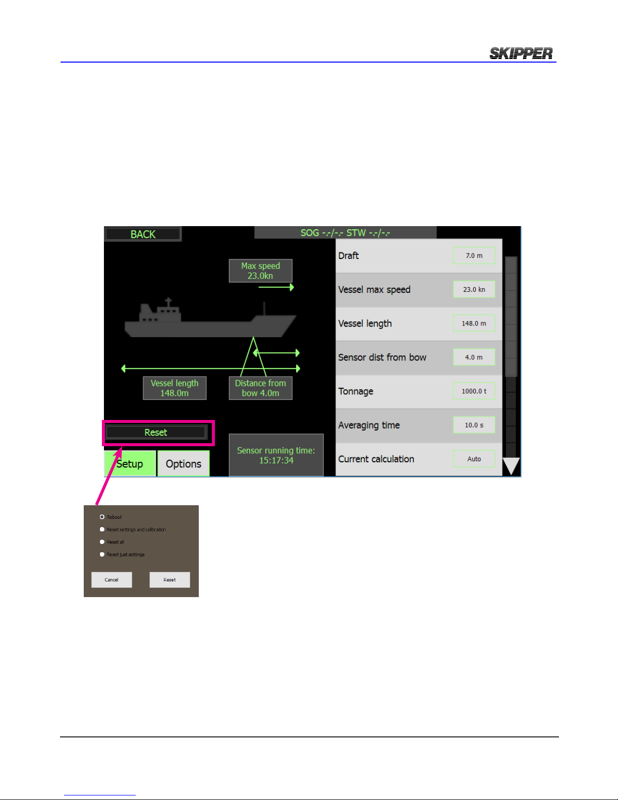
reseT
There are 4 available reset options.
1. Reboot of software
2. Reset settings: Will reset settings for NMEA, AUX and DL2 setup back to default.
3. Reset settings and calibration: Will also set calibration settings to default.
4. Reset all: Will set the system calibration and communication settings (IP) back to default
Page 34
Page 34 of 60
2018-05-28
Installation DL2 Doppler Speed Log System
sOfTware OpTiOns
The DL2 system has a number of options available. The software and hardware in this product is
designed to meet the requirements of MED and IEC 60945. The product in its standard form is limited
to meet the specication required. However,it is designed to allow adjustments and improvements
to be implemented so that the product can be used in markets requiring higher specication and
functions not standard in a commercial speed log.
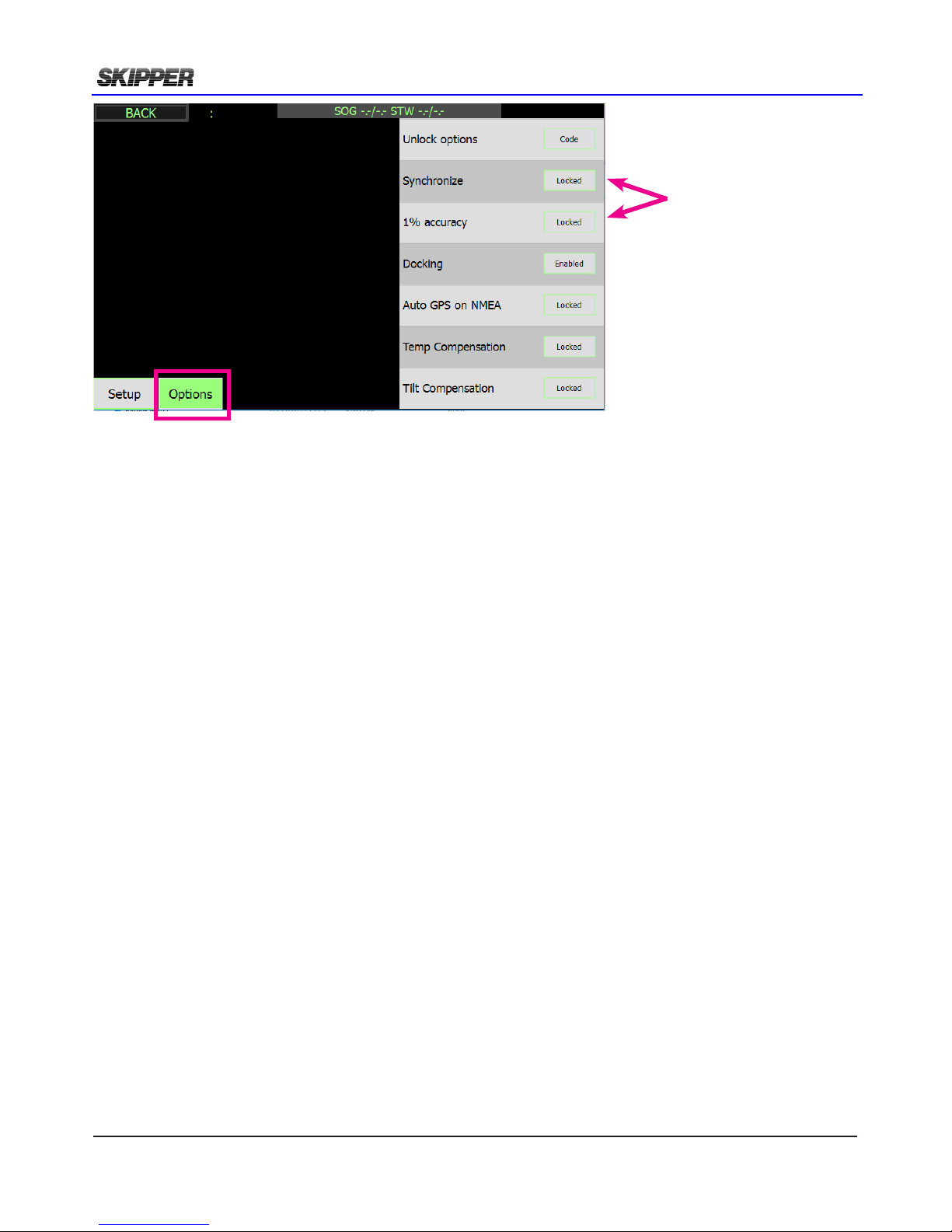
There are currently 2 available purchase options. These are activated by entering the code provided
by SKIPPER in the correct eld. All options can be activated in retrospect (at an additional cost) by
giving the system serial number to SKIPPER, they will send the activation code in return
Purchase options
- 1% accuracy
DL2 is default 2% accuracy. Activating 1% accuracy option will give the option in the DL2 menu,
and in each NMEA output menu, to congure to show 1 or 2 decimals, on the screen values and
NMEA sentences.
Will enable a set of lters and features that will ensure and check, that the unit is operating within
1% specication.
- Synchronize
This option enables the user to send a mute signal to stop the sensor from pinging.
There are 2 syncronize input options:
• AUX level into the aux input to stop the sensor.
• NMEA message input $PSKPBLNK,2,1,ON*nn or $PSKPBLNK,2,1,OFF*nn where ON is
mute
There are 2 synchronize output options:
• AUX “SyncOut” will give a pulse out when sensor is conrmed muted from external input.
• AUX “PingOut” will give a pulse out when sensor is pinging.
Please note!
The sensor pinging is a very short repeating pulse of 1-8milliseconds.
Due to electronics delay the sensor will mute 8ms after a level change on the Aux input.
When Synchronize is active a warning M will be shown on the screen, after 10 seconds of mute,
the system will detect this as a sensor failure and give a system alert.
Purchase options
Page 35

2018-05-28
Page 35 of 60
Installation DL2 Doppler Speed Log System
Non-Pay options
Docking
Auto GPS on NMEA
Temp compensation
Tilt compansation
Activating/de-activating software options.
Software options can be activated and de-activated in the DL2 menu. This page contains a table
where the installer can enter codes purchased/supplied from SKIPPER. Codes will only activate if
they detect the correct hardware in place. Codes are unique to the serial number of the system and
can not be moved from system to system. To remove an extra option, the user must re-enter the
code number.
Page 36
Page 36 of 60
2018-05-28
Installation DL2 Doppler Speed Log System
cOmmunicaTiOns seTup (nmea/udp)
nmea
The most common communication method to this type of system is the IEC61162-1 NMEA ports,
these use an isolated input RS422 diferential method. The IEC61162-1 standard requires 4800
baud, 8 databits, 1 stop bit and no handshake. The system also supports faster communications
as specied in the IEC61162-2 standard using 38400 baudrate. If this standard is to be used the
output requires a common connection available on J2 pin 11 or pin 12.
It is also possible to run the system at 115200 baud, although there is no standard to support this.
lan udp
In addition, this unit supports the LAN UDP standard (IEC61162-450)
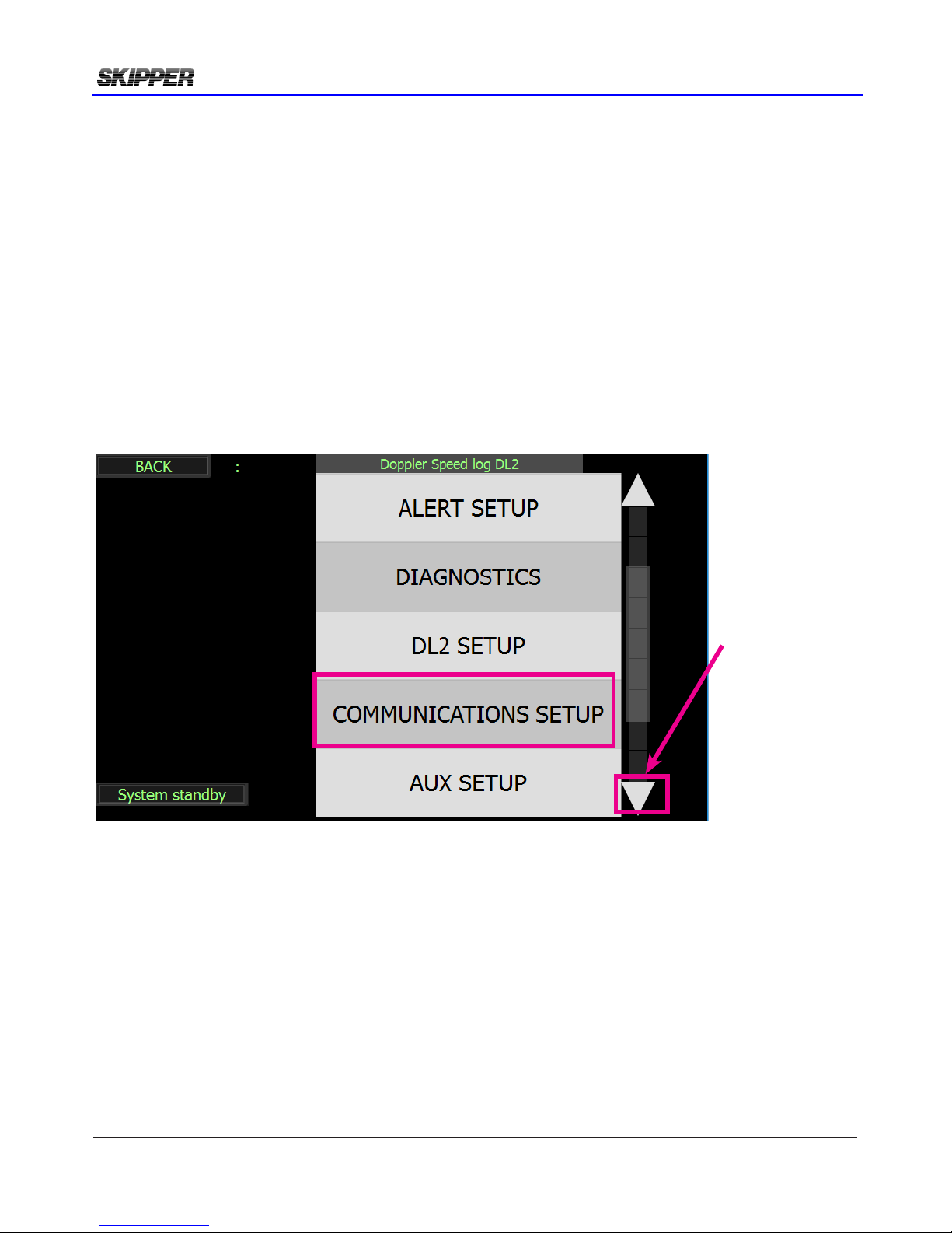
Communication setup page is accessed via cong menu.
Scroll down with the right sid arrow until “Communication setup” button is displayed.
Scroll down
Page 37
2018-05-28
Page 37 of 60
Installation DL2 Doppler Speed Log System
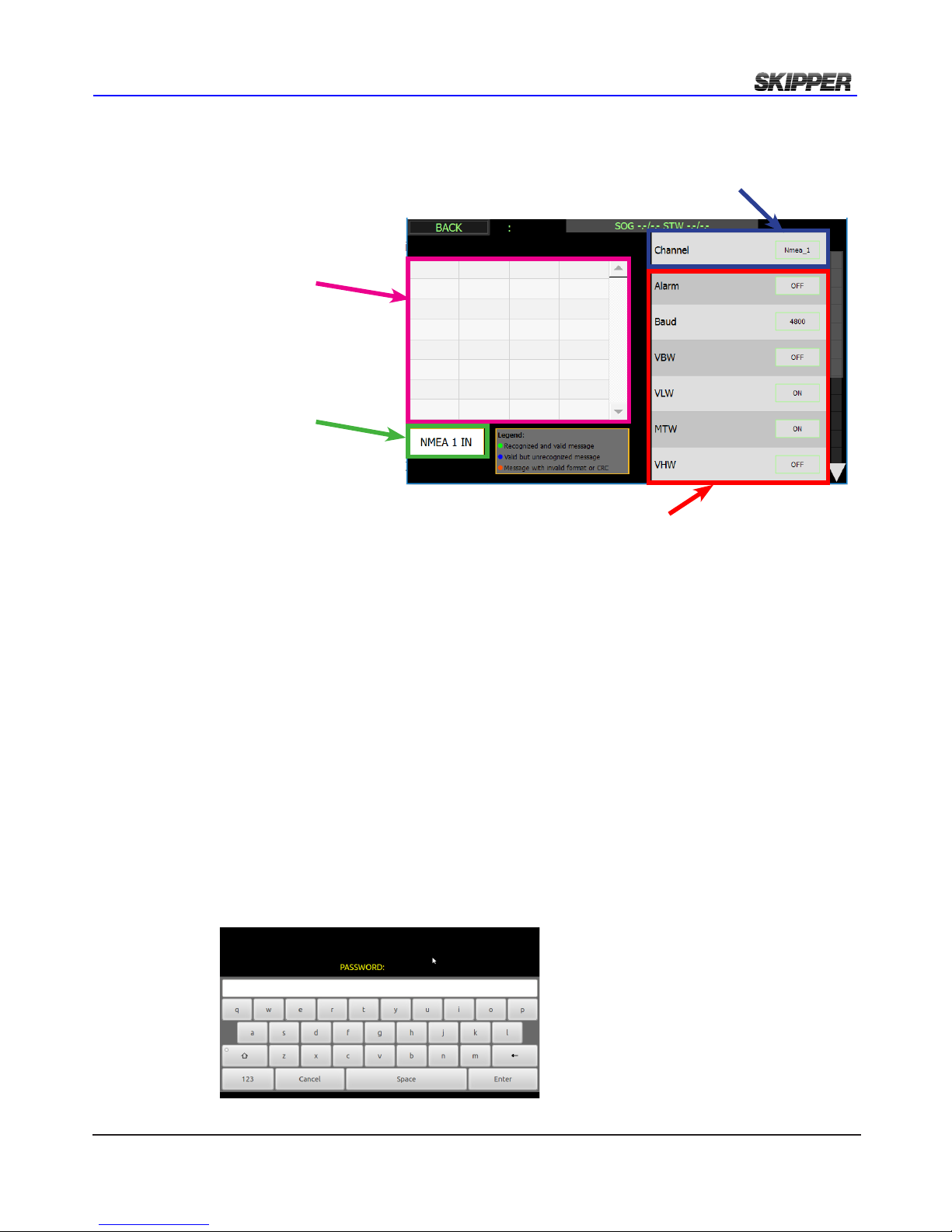
For each of the outputs 1, 2 and LAN (UDPM) it is possible to activate a number of sentences.
Normally with On and Off. The resulting outputs are shown on the left on the screen.
The alarm output has 3 choices ALR, ALF and OFF. This because only one of these should be
selected at a time.
Output settings are password protected for changes.
The password for all units is ‘service’. The password will be remebered for 1 hour, or until reboot
of the system.
Window will show sentences In/Out from
NMEA1, NMEA2 or UDP
In/Out select
Select NMEA1, NMEA2 or UDP
Output sentences settings for
NMEA1, NMEA2 and UDP
Page 38
Page 38 of 60
2018-05-28
Installation DL2 Doppler Speed Log System
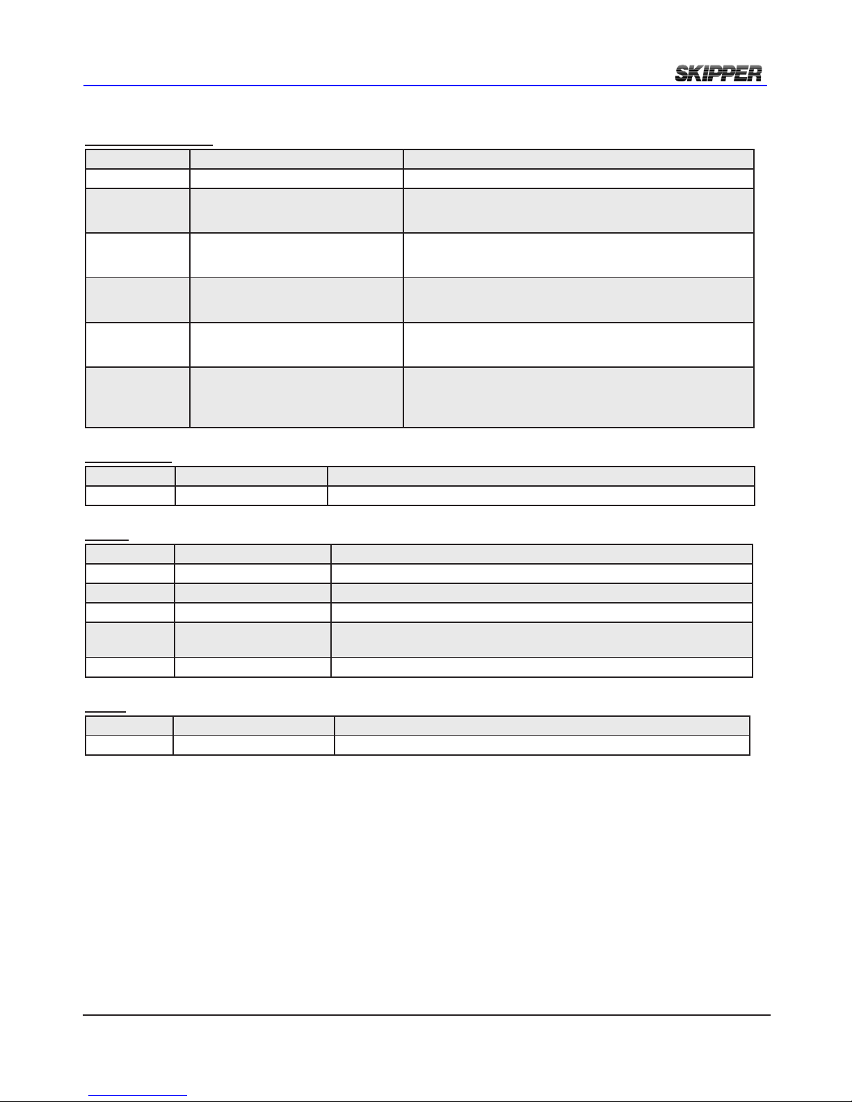
NMEA sENtENcEs rEcEivEd
If input is shown, then the system will colour code the headers to show if the data is recognised,
and correct, recognised and not correct, or not recognised/used
All channels will detect inputs and automatically use those that are recognised
Time
Day, month, year ZDA,hhmmss.ss,xx,xx,xxxx,xx,xx*hh<CR><LF>
Position
Geographical lat/lon GLL,llll.ll,a,yyyy.yy,a,hhmmss.ss,A,a*hh<CR><LF>
GPS position GGA,hhmmss.ss,llll.ll,yyyy.yy,a,x,xx,x.x,x.x,M,x.x,xxxx*hh <CR><LF>
Rate of Turn
Rate of turn ROT,x.x,A*hh<CR><LF> (Required for docking.)
Alarm
Acknowledge alarm ACK,xxx*hh<CR><LF>
ACN,hhmmss.ss,aaa,x.x,x.x,c,a*hh<CR><LF>
Heading
Heading, true, present HDT,xx.x,T*hh<CR><LF>
True heading and status THS,x.x,a*hh<CR><LF>
Composite
Loran C specic RMA,a,xxxx.xx,N,xxxxx.xx,W,,,xx.x,xxx.,,*xx<CR><LF>
GPS, transit specic RMC,hhmmss.ss,A,llll.ll,a,yyyy.yy,a,x.x,x.x,xxxxxx,,,*hh <CR><LF>
External trip reset over NMEA
Trip reset
In SOG only mode Trip reset
to DL2 will be transferred to
DL1.
$PSKPRSTT*<hh><CR><LF>
Trip and total adjust $PSKPSTL,<trip>,<Total>*<hh><CR><LF>
External dimming over NMEA
External dimming of display unit $--DDC, a, xx,a*hh<CR><LF>
Placing a system in standby
Set a system in standby or wake up
$PSKPSLP,<target SFI>,<sleep value>*hh
command added for setting system to sleep or waking up.
<target SFI> can be JB’s SFI or SFI of a display paired
with JB of a particular system, <sleep value> is “1” or
“0”, “1” - sleep
A number of proprietary inputs may also be present (particularly on the LAN channel) to communicate
with the display and JB70 unit
Page 39
2018-05-28
Page 39 of 60
Installation DL2 Doppler Speed Log System
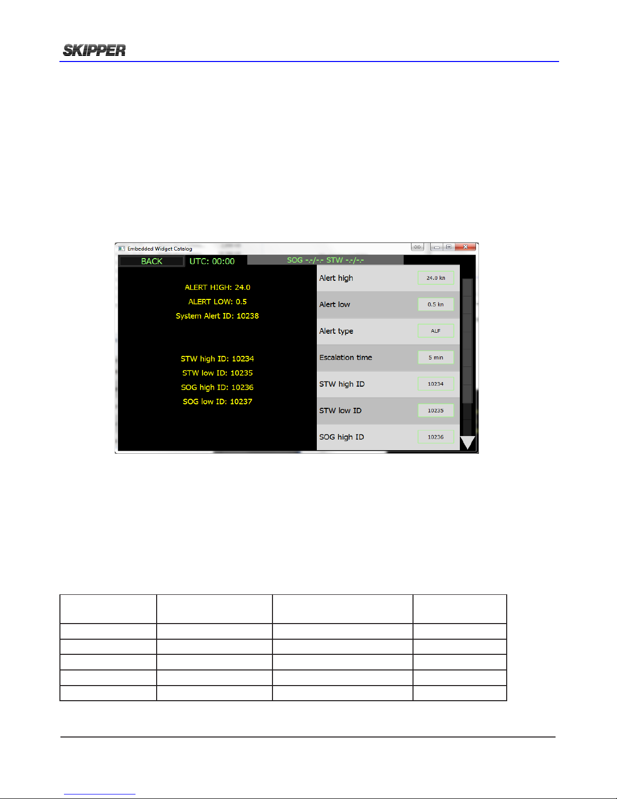
nmea senTences TransmiTTed
(talker) (IEC 61162-1:2007(E) (NMEA 0183) messages:
Speed and distance
Name Description Example
VTG
Course over ground and ground speed $VDVTG,,,,,x.x,N,x.x,K,a*hh<CR><LF>
VHW
Water speed and heading
(In a DL21 “SOG only” mode VHW will show
water speed from DL1)
$VDVHW,,,,,x.x,N,x.x,K*hh <CR><LF>
VLW
Dual ground/water distance
(In a DL21 “SOG only” mode VLW will show
water trip and total from DL1)
$VDVLW,x.x,N,x.x,N*hh<CR><LF>
VLW IEC07
Dual ground/water distance
(In a DL21 “SOG only” mode VLW will show
water trip and total from DL1)
$VDVLW,x.x,N,x.x,N,x.x,N,x.x,N*hh<CR><LF>
VBW
Dual ground/water speed
(In a DL21 “SOG Only” mode VBW rst eld
will show data from DL1 STW)
$VDVBW,x.x,x.x,A,x.x,x.x,A,x.x,A,x.x,A*hh <CR><LF>
VBWX
Dual ground DL2/water DL1 speed
(In a DL21”SOG+STW” mode VBWX will
show SOG data from DL2 and STW data from
DL1.)
$PSKPVBWX,x.x,x.x,A,x.x,x.x,A,x.x,A,x.x,A*hh <CR><LF>
Temperature
Name Description Example
MTW
Water temperature $VDMTW,x.x,C*hh<CR><LF>
Alarm
Name Description Example
ALR
Set alarm state $VDALR,hhmmss.ss,xxx,A,A,<Alarm message> *hh<CR><LF>
ALF
$VDALF,x,x,x,hhmmss.ss,a,a,a,aaa,x.x,x.x,x.x,x,c---c*hh<CR><LF>
ALC
Cyclic alert list $VDALC,xx,xx,x.x,aaa,x.x,x.x,x.x,...,aaa,x.x,x.x,x.x*hh<CR><LF>
ARC
Alert command refused
(Not in use by DL2)
$VDARC,hh,mm,ss.ss,aaa,x.x,x.x,c*hh<CR><LF>
HBT
Heartbeat $VDHBT,xx,A*hh<CR><LF>
Depth
Name Description Example
DPT
Depth $IIDPT,x.x,x.x*hh<CR><LF>
Values will be preceded with sign as needed ( e.g “-“ = Astern, Port).
*hh = Checksum.
Page 40
Page 40 of 60
2018-05-28
Installation DL2 Doppler Speed Log System
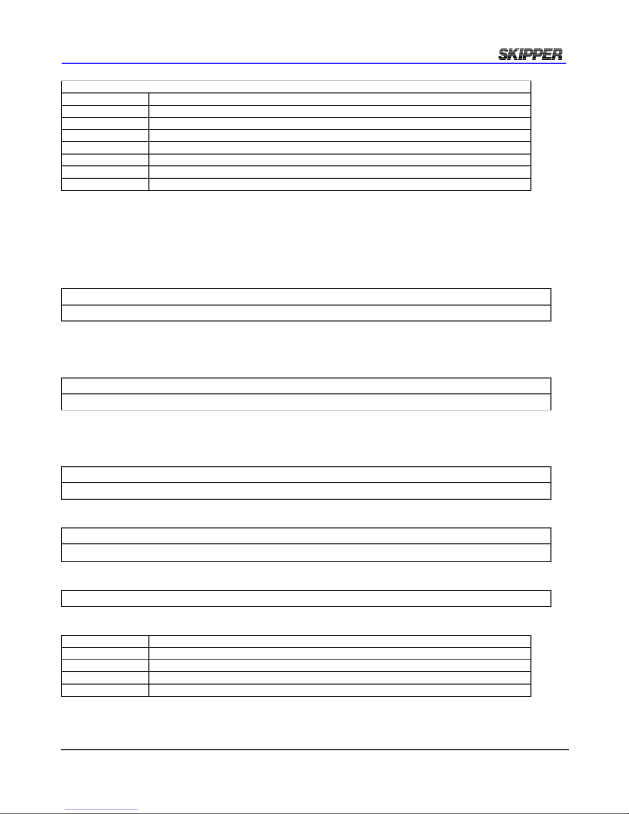
Remote acknowledge can be set up by aux input, by ACK or ACN (both from NMEA port and LAN).
Alarms are available for low speed (SOG and STW), high speed(SOG and STW) and system failure.
They can be activated or deactivated and given a unique alarm ID. Each alarm has its own unique
ID and message, and can be deactivated by making the ID zero.
The messages in use are as follows:
Alarm type Alert identier
(adjustable*)
Alert Text Mnemonic code
SOG SPEED HI 10234 ‘SOG Speed Hi’ SKP
SOG SPEED LO 10236 ‘SOG Speed Lo’ SKP
STW SPEED HI 10235 ‘STW Speed Hi’ SKP
STW SPEED LO 10237 ‘STW Speed Lo’ SKP
SYSTEM warning 10238 ‘SYSTEM ALARM’ SKP
* Note some systems may only accept 3 digits in ALR messages. In this case remove the 10XXX
alarm/alerT seTup
According to INS standard IEC61924-2 Annex C speed logs may be able to handle “Speed Low
Alarm” as a Category B alarm. Acknowledge can be remote.
The DL2 has 4 I/O options for alarm communication:
-NMEA ALR/ALF message
-LAN ALR/ALF message
-AUX optocoupler
-Alarm relay
Page 41
2018-05-28
Page 41 of 60
Installation DL2 Doppler Speed Log System
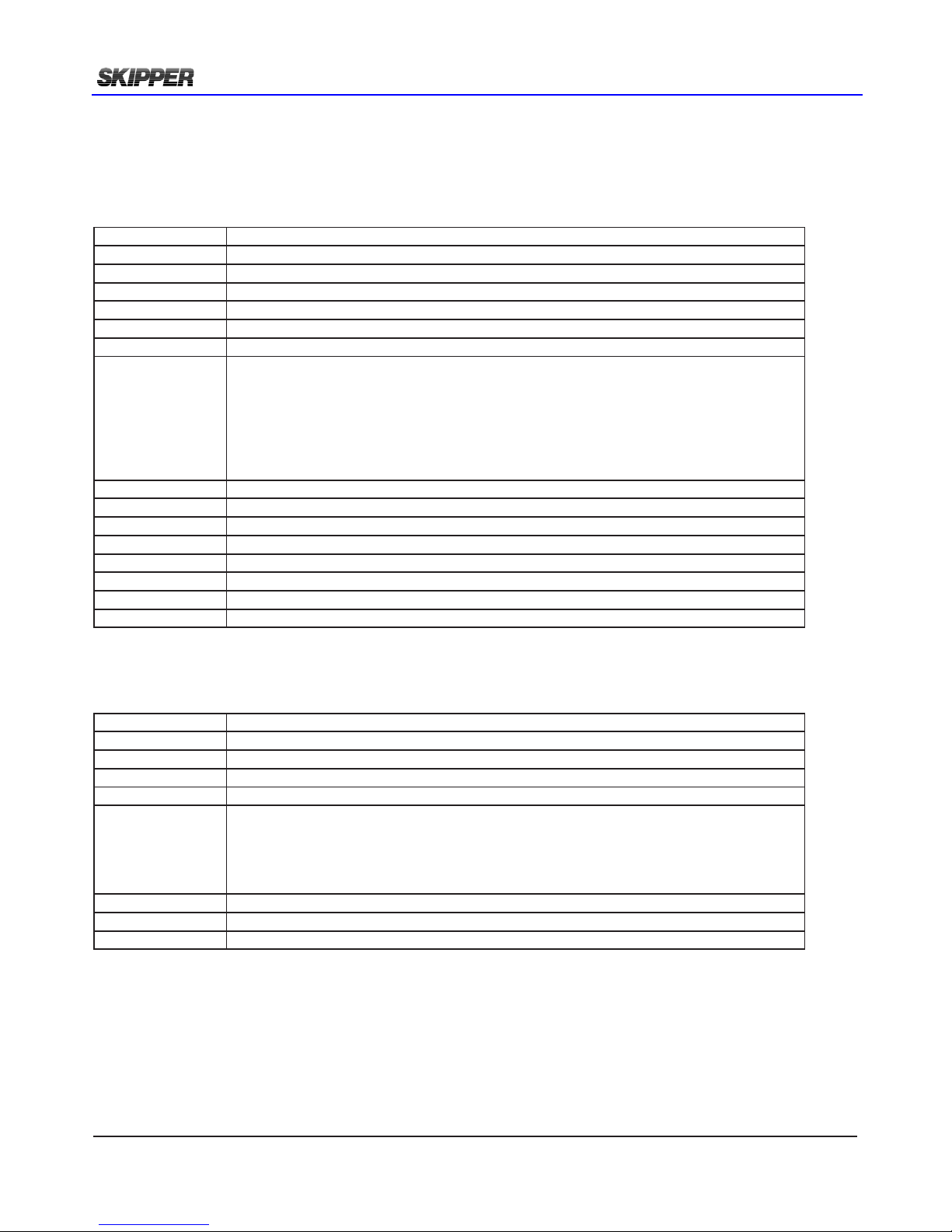
transmit) ALR messaging
$VDALR,hhmmss.ss,xxx,A,A,<Alarm message> *hh<CR><LF>
$VDALR ALR message from VD (=Velocity Doppler)
hhmmss.ss Time of alarm condition change, UTC
xxx Unique alarm number (Id) at alarm source.
A Alarm condition. A=Treshold exceeded, V=Not exceeded.
A Alarm acknowledge state. A=Acknowledged, V=Unacknowledged.
<Alarm message> Alarm description text: “Low speed” or “High speed”
hh Checksum
<CR><LF> Carriage return and line feed (Normally not visible)
Initially at “no alarm” no messages will be sent , occasionally $VDALR,,V,V,*nn.
If one of the “Low speed” or “High speed” alarms are exceeding treshold, the alarm exceeding threshold will
send an alarm message. In below example WT and BT has exceeded “High speed” treshold.
The unique alarm number (Id) is as shown in the alarm type table above, A is “Alarm condition” “Exceeded”.
V is “Unacknowledged” state.
$VDALR,152609.17,10235,A,V,STW Speed Hi*nn
$VDALR,152609.17,10234,A,V,SOG Speed Hi*nn
If the touch display is touched or ACK acknowledge command is sent to DL2.
A is “Alarm condition” “Exceeded”.
A is “Acknowledged” state.
$VDALR,152619.17,10235,A,A,STW Speed Hi*3B
$VDALR,152619.17,10234,A,A,SOG Speed Hi*2C
When speed is again inside treshold ALR message will change to “No alarm”, “Acknowledged” on all.
V is “Alarm condition” “Not exceeded”.
A is “Acknowledged” state.
$VDALR,152725.75,10235,V,A,STW Speed Hi*26
$VDALR,152725.75,10234,V,A,SOG Speed Hi*31
If the user acknowledges, the sentence will show 1 time the acknowledged state
$VDALR,152725.75,10235,V,V,STW Speed Hi*26
$VDALR,152725.75,10234,V,V,SOG Speed Hi*31
and then return to its normal state of sending
$VDALR,,V,V,*26
at least 1 time per minute (HBT sentence is also sent every minute)
(receive)ACK Acknowledgement (works if ALR is activated)
$_ _ ACK ACK acknowledge header
Time of alert command UTC (if available)
x..x Alert identier
hh Checksum
< CR><LF> Carriage return and line feed
Page 42
Page 42 of 60
2018-05-28
Installation DL2 Doppler Speed Log System
transmit) ALF messaging
The DL2 alarms are classed as category B, and can use the full prototcol of INS alarming.
At time of print ALF is the most modern and recommended standard for alarming. (IEC61924-2 and its
corregendum 1) This alarm method should not be used at the same time as ALR.
ALF message works in conjunction with ACN, HBT, and ALC is dened
$VDALF ALF message from VD (=Velocity Doppler)
x Total number of ALF sentences (1)
x Sentence number (1)
x Sequential message identier (1)
hhmmss.ss Time of alarm condition change, UTC (if available)
a Alert category (B)
a Alert priority, E A W or C (A)
a Alert state A,S,N,O,U or V
V= Active unacknowledged (Like ALR A,V)
S= Silenced
A=Active acknowledged (Like ALR A,A)
O = Responsibility transfered
U = Rectied unacknowedged (Like ALR V,V,...)
N = Normal (like ALR V,V with no ID)
aaa Manufacturer mnemonic code (SKP)
x..x alart identier
x..x alert instance 1-999999”
xx Revision counter 1-99
x Escalation counter 1-9
c--c Alert text (see list of alarm types)
hh Checksum
<CR><LF> Carriage return and line feed (Normally not visible)
example
$VDALF,1,1,0,124304.50,B,W,V,10234,SKP,1,1,SOG Speed Hi*hh
(received) ACN Acknowledgement (works if ALF is activated)
$_ _ ACN ACN acknowledge header
Time of aalert command UTC (if available)
aaa Manuafacturer Mnemonic (as in alarm types table)
x..x Alert identier
x..x Alert instance
c Alert command A,Q,O,S
A= Acknowledge
Q= Request to repeat ALF
O= responsibility transfer
S= silence
a Sentence status ag
hh Checksum
< CR><LF> Carriage return and line feed
Example
$IIACN,124305.50,10234,SKP,A,A*hh
Page 43
2018-05-28
Page 43 of 60
Installation DL2 Doppler Speed Log System
(transmit) ALC Cyclic alert list (sent every 30 seconds when ALF is activatied)
If the system receives this command, it will resend the active ALF sentences
$_ _ ALC ALC header
xx total number of sentencesfor this message
xx sentence number
xx sequential message identier
x..x number of alert entries
aaa manufacturer mnemonic code
x.x alert identier
x.x alert instance
x.x revieion counter
..... additional alerts
aaa manufacturer mnemonic code
x.x alert identier
x.x .....alert instance
x.x .....revision counter
hh Checksum
< CR><LF> Carriage return and line feed
(transmit) HBT Heartbeat (sent every 60 seconds if ALR or ALF are selected
$VD HBT Heartbeat header
xx Congured repeat interval (60 sec)
A Equipment status (A,V)
x Sequential sentence identier (0-9)
hh checksum
< CR><LF> Carriage return and line feed
Alarm using relay and AUX function
All ports marked AUX can de dened in the AUX setup. All AUX ports are isolated, most with optoisolators
requiring a voltage to make them operate. 1 AUX output is a relay output and this can be used for normal
alarm use or as a switch for a sounder (The system does not contain a sounder and this must be connected if
the alarms are to be used without an external alarm system)
By default AUX input 1 is used for alarm reset, the relay is used for alarm output. A second AUX output can be
used as a separate power failure alarm if required. If the relay is used for an alarm sounder, then AUX should
be set to ‘alarm beep output’. This will cause a beep 3 times every 7 seconds while an alarm is active and not
silenced.
Testing Alarm functions
On the Diagnostic conguration screen, it is possible to press a test alarm button. This will cause an alarm
using the settings in place. an ‘S’ will be shown on screen to indicate an alarm simulation is in progress.
IMPORTANT This system does not contain an acoustic sounder for alarm. If no central
alarm system is installed, then a separate sounder must be installed. This sounder must
beep at between 75 and 85dBA (as specied in IEC60945 §11.1.3)
Page 44
Page 44 of 60
2018-05-28
Installation DL2 Doppler Speed Log System
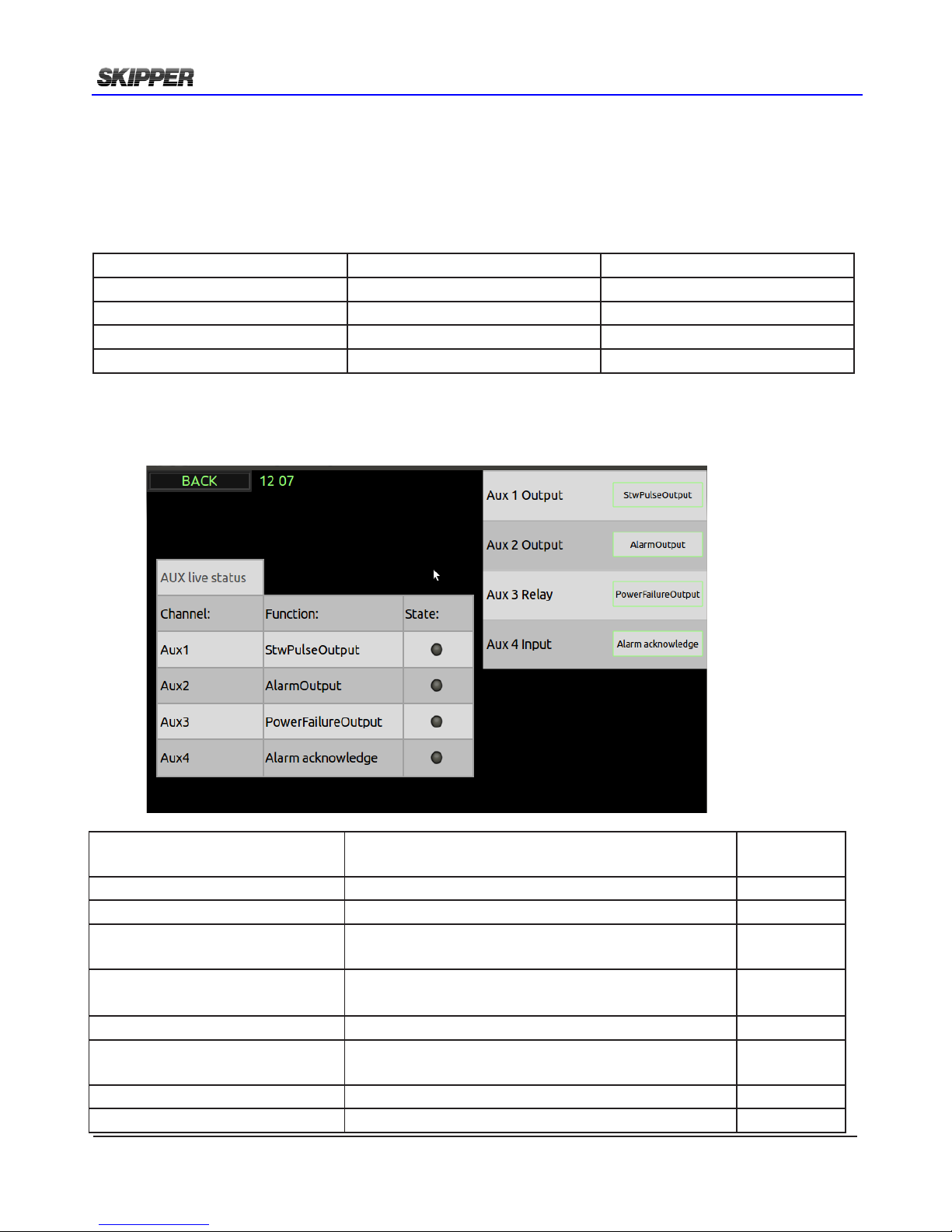
seTup aux
The Auxiliary inputs and outputs can be assigned to different functions in the AUX Setup screen.
If Speed warning is selected on one of the output channels, then the user can set a high and low
limit. At this speed the state of the output will change.
The current state of the AUX input and outputs are shown in the table below
Name Type Pin numbers (J2 Aux)
Aux 1 Output Opto-isolator 7 +, 9 Aux 2 Output Opto-isolator 2+, 4Aux 3 Relay Relay 1 NC, 3 Com, 5, NO
Aux 1 Input Opto-isolator 2+, 4-
Speed warning changes the output state as the vessels speed passes a set speed, this can have 2
values low and high. These values are set using below buttons.
NOTE. Do not use the Aux 3 Relay output for pulse speed output as the relay has a limited number
of switching cycles.
Options for the Auxilliary output are.
Option Description Option Code
required?
STWPulseOutput 200 PPNM showing STW No
SOGPulseOutput 200 PPNM showing STW No
AlarmBeepOutput The output will click 3 times every 7 seconds when
an unacknowledged alarm is active
No
AlarmOutput The state will change when an unacknowledged alarm
is active
No
SpeedLimit The State will change when it enters the speed zone No
AlarmReset (input) All active alarms will be acknowledged when the
state of this is changed
No
Mute (input) The sensor is silenced when this is active Sync Option
Synch Out When the sensor is conrmed silenced, this changes Sync Option
Page 45
2018-05-28
Page 45 of 60
Installation DL2 Doppler Speed Log System
sysTem diagnOsTics
The Diagnostics screen allows the user to test the system, activating alarms and outputing set
speeds. It is also possible to perform self test of the system and check the status.
Self test will perform the following actions:
• Check internal voltages and compare them to defaults and installation references.
• Check connectivity and connected items.
• Disconnect NMEA ports and loop back to check circuit function.
• Measure function of the sensor (pinging between channels and analyse returning signals).
To test other systems connected to this system, a data test is available, allowing output parameters
to be entered and given out on all the activated outputs. In addition, an alarm condition can be
simulated and acknowledged. For demonstration, a simulator can be activated to show a recorded
data set over time. This function will turn off automatically after 6 hours or on power reset.
Speed simulation is a full check of the system. The speed information is set to the sensor and the
sensor produces frequencies corresponding to the desired speed. In this way all parts of the system
are in use, and this in itself is a good diagnostic check.
available OpTiOns in The diagnOsTic page
• Simulators
• Speed
In this page it is possible to set a xed speed and send this to the sensor. This will result in the
speed being presented on all displays and outputs. This mode is a full simulator and will verify that
all electronics and processing in the system are operational. When active an orange ‘S’ will show
on screen.
• Alarm
By pressing the alarm simulator a typical alarm will become active. this can be acknowledged as
normal, and will disapear when the simulator is removed.
errOr messages
The following error cases are accounted for.
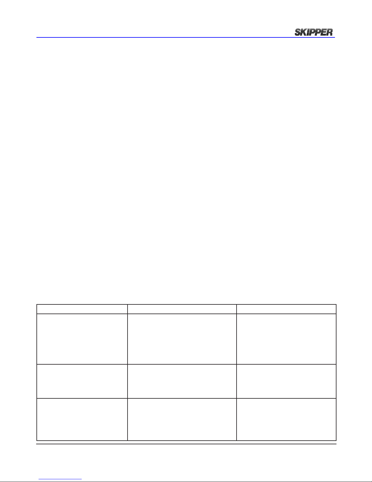
Error description How you see it Possible fault
Data from sensor missing. On the screen the data disapears and
is replaced by ‘-.-’
The JB70 unit will send a system
alarm.
The status LEDS on JB unit shows
constant orange
The sensor is not sending data.
Check cabling between sensor and
Electronic unit.
Data from sensor wrong On the screen the data disapears and
is replaced by ‘-.-’
The Status LEDS on JB70 unit will
ash orange
Sensor is not able to measure the
speed.
Loss of communication between display unit and electronic unit.
On screen the following warning will
occur ‘Lost communication’
The JB70 unit will send a system
alarm.
The pairing between the Display
unit and Electronic unit has failed.
Check your cabling and check
setup. (SKIPPER service software
may be used)
Page 46
Page 46 of 60
2018-05-28
Installation DL2 Doppler Speed Log System
1 The Display does not connect with the JB70 electronic unit
(Shows ‘NO CONNECTION’)
The display connects using a UDP LAN protocol. Both units must be set up to have an ID number
and IP address. The skipper service software can be used to simply reassign all these values.
Skipper service software available from the download pages of www.skipper.no.
2 No data from the sensor (the screen shows -,- instead of STW value)
This can be due to cabling issues to the sensor or sensor failure. Go to the cong Diagnostics page,
and run a self test. This will report no detected sensor, in this case. most likely problem is wrong
cabling, but maybe the voltage is too low for the sensor. Measure the voltage at the junction near
the sensor. This voltage should be >15V
If it is lower, remove the cable from the electronic unit and loop the end cable at this point, and
measure the loop resistance. It should be according to the specication shown in chapter 2. THe
vaalues supplied for installation are worst case and the sensor will work normally with a loop
resistance of up to 16 ohms.
If the voltage is ok at this point, check the NMEA output of the sensor (Blue/green) to check the
sensor is operational. You can also measure current taken by the sensor, it should be in the region
of 200mA at 24V (5W) and pulsing higher.
If this is not the case, try connecting a power supply with 24V directly to the sensor (Green +24V,
Brown 0V) to see if unit starts.
If all this fails, there may be an error in the sensor.
saving and lOcKing
The parameters will be automatically saved and if the the individual units of the system loose
communications, they will re-synchroinize when they reconnect.
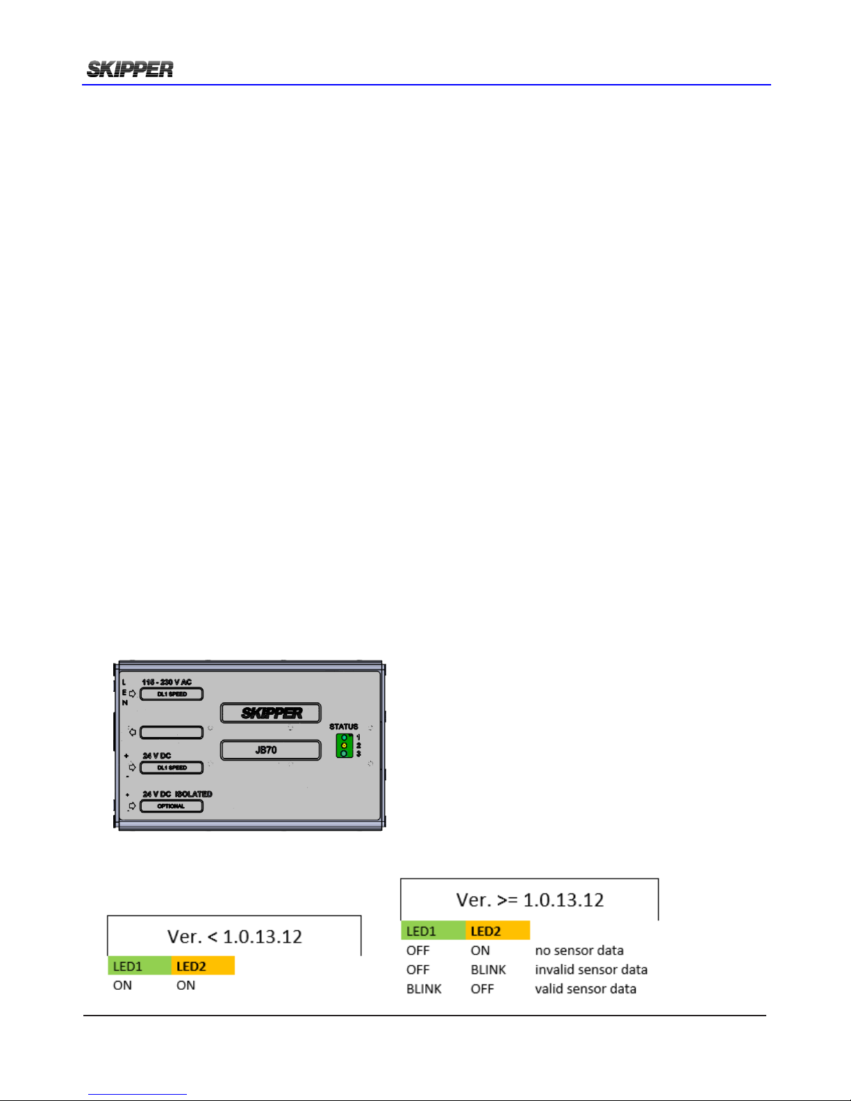
STATUS LED 1(Green) DL2
STATUS LED 2(Yellow) DL2
STATUS LED 3(Green) only in use in DL1
sTaTus leds
There are 3 status LEDs found on the JB70 Electronic unit.
The green and yellow LEDs are in use by the DL2. Functionality depending of software version.
Page 47

2018-05-28
Page 47 of 60
Installation DL2 Doppler Speed Log System
hardware OpTiOns
In addition to the mechanical options and software options, it is possible to select hardware options.
These require an additional PCB and front plate. See appendix 3.
Dual system (DL21)
The DL2 (JB70D2 electronic unit) can also be upgraded with an extension card where the card can
be used as a separate single axis Doppler speed log. In addition to the PCB, an additional sensor or
the sensor of type DL21S is required. This sensor contains both 2 axis (270 kHz) transducers, but
also a single axis (715 kHz) speed log within the same housing. New regulations for vessels over
50 K GRT (Gross Register Tonnage) state that the vessel must have separate (electrically isolated)
systems for speed over ground and speed through water. This system and the use of auxiliary +24
V DC power on the JB70D2-X electronic unit meets this criteria. A CD402CU-XX control unit will also
be required for the secondary system.
Page 48
Page 48 of 60
2018-05-28
Installation DL2 Doppler Speed Log System
CHAPTER 6: SOLVING PROBLEMS
The following section covers envisaged problems with the system.
sOfTware upgrade
The DL2 sytsem consists of 3 software packages, All of these can be upgraded via the LAN interface.
To do this download the SKIPPER service software from www.skipper.no. Install this on a PC and
then connect to the unit, either through the ships network or directly. Then follow the instructions in
the software.
As this product is new, there will be frequent improvements added to the software. Please monitor
the SKIPPER web site to see if these are useful for you.
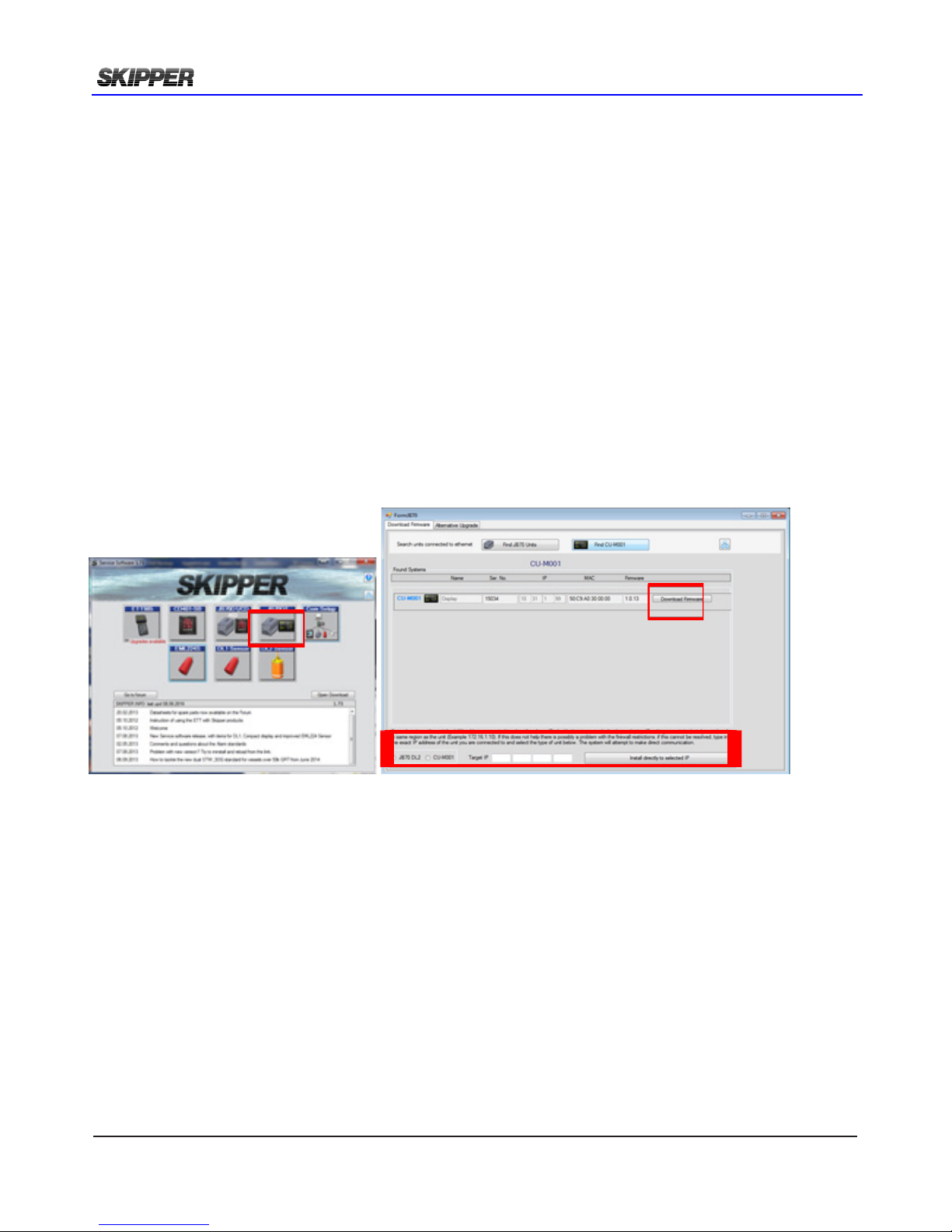
To upgrade select Come setup and search for systems. Check you can see the systems you are
connected to. Set your PC’s Network settings to Static ip address with address 172.16.1.95
Search with the software.
Close this window and go to the JB70D2 window. Search for the part to be uograded.
Press Download Firmware and follow the instructions
If you do not see the system you are connected to, type the IP address into the lower window. and
select the system type (Default JB70D2 is 172.16.1.101, CU-M001 is 172.16.1.102
Then select the software
SW-M004 for JB70DL2 Electronic unit
SW-M005 for CU-M001 Display
More updated information will be available on the SKIPPER forum (www.skipper.no/smf) and in the
data bullitins
Page 49
2018-05-28
Page 49 of 60
Installation DL2 Doppler Speed Log System
APPENDIX 1: INSTALLATION DRAWINGS
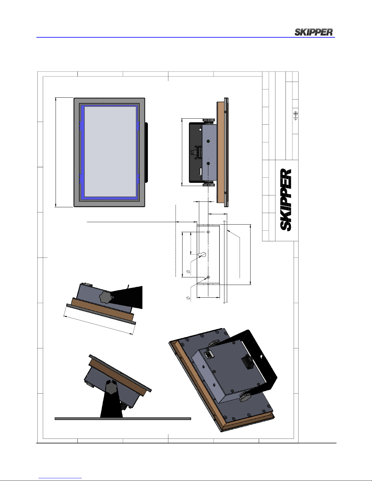
Operator unit desk/wall mount dimensions
242
158
148,50
42
Front perpendicular
to the wall
Wall mounted
50
100
20
133
5,5 10
50
Recommended cabling space: 35 mm
Desk mounted
E
F
C
1
2
3
4
B
A
3
2
1
5
C
D
4
6
7
8
A
B
D
E
ISO2768m
X:X
Gen. tolerance
Eur. projection
XXX
Material
YYYY.MM.DD
Checked by
XX-XXX XX
Date
CN
Drwg. no.
Name
XXX
Edition date
Sheet
1246
Revision
CU-M001-SA
Scale
Multi-PanelPC 9inch display-deskmount 2-
mechanical diagram
X of X
Designed by - date
XXX
XXX YYYY.MM.DD
Approved by - date
Electronics AS
Page 50
Page 50 of 60
2018-05-28
Installation DL2 Doppler Speed Log System
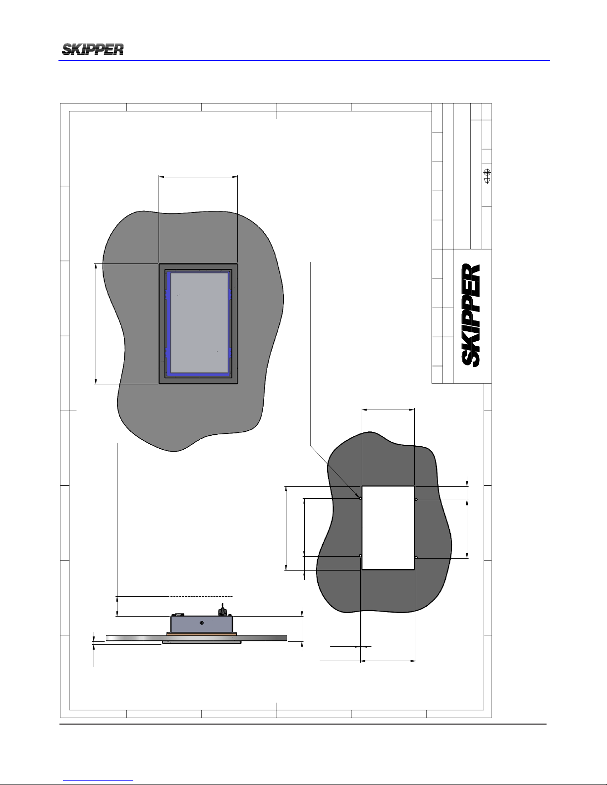
Operator unit Flushmount dimensions
158
242
224,5
140
37 155
4,10
148,20
37 155
Mountingholes for screw, self tapping Ø3,5 ISO 14585-F
6
51
Recommended cabling space: min. 40 mm
CUT - OUT
E
F
C
1
2
3
4
B
A
3
2
1
5
C
D
4
6
7
8
A
B
D
E
ISO2768m
X:X
Gen. tolerance
Eur. projection
XXX
Material
YYYY.MM.DD
Checked by
XX-XXX XX
Date
CN
Drwg. no.
Name
XXX
Edition date
Sheet
1246
Revision
CU-M001-SA
Scale
Multi - PanelPC 9inch display-flushmount 1
1 of 1
Designed by - date
XXX
A.Matre 2014.05.19
Approved by - date
Electronics AS
Page 51
2018-05-28
Page 51 of 60
Installation DL2 Doppler Speed Log System
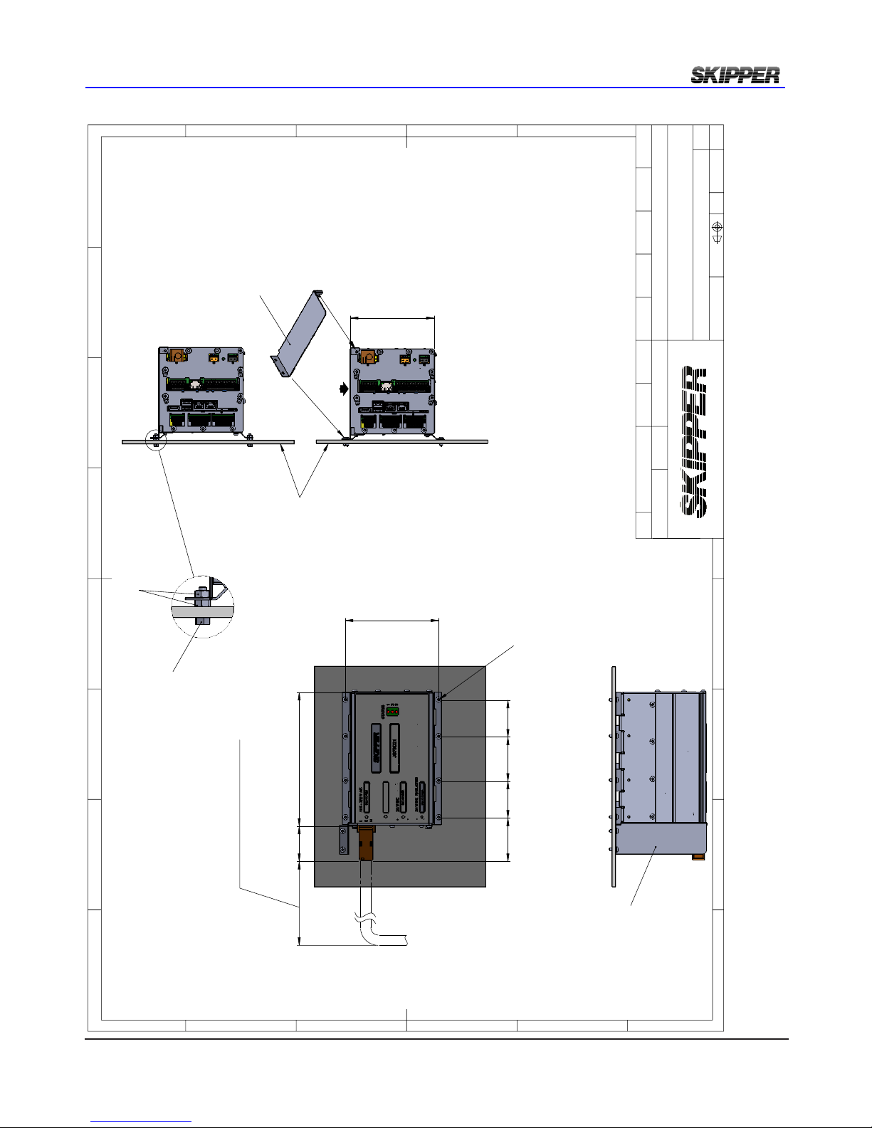
Electronic unit JB70 Dimentional drawings
114
IP22 approved mounting
50 60 50
127
181,5
48
59
Use self tapping screw ST3,5 DIN7985-C, or equal (The screw length depends on condition of the wall)
Holes in the mounting strip = Ø3,7 mm
Recommended min. free space 133,5"
Existing wallExisting wall
Screw M3,5 x 14 (10x)
Nut M3,5
Nut M3,5 (20x)
Drip protector
ZAA-01330 Drip plate for JB70
Alternative assembly
E
F
C
1
2
3
4
B
A
3
2
1
5
C
D
4
6
7
8
A
B
Electronics AS
D
E
ISO2768m
1 : 3
Gen. tolerance
Eur. projection
As Parts
Material
2017.03.08
Checked by
ST 2017.03.08 Changed free space
from 50mm to 133,5 inch.
CN
Drwg. no.
Name
GT 2017.03.10
Edition date
Sheet
00
Revision
JB70DXX-SA
Scale
JB70DXX-SA mounted at wall
1 of 1
Designed by - date
PC
A.Matre 2012.10.31
Approved by - date
Page 52
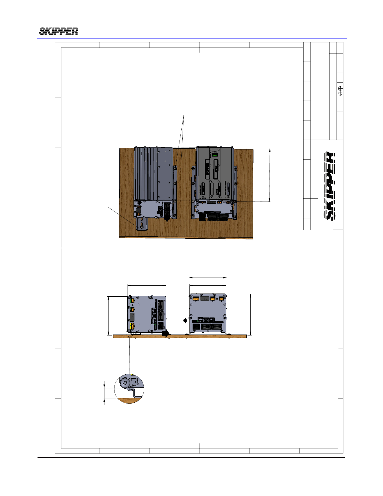
Page 52 of 60
2018-05-28
Installation DL2 Doppler Speed Log System
115
114
109
116,5
123
IP22 approved mounting
181
Mounting rail DIN50 (min. 260 mm)
A
7,6
DETAIL B
SCALE 4 : 3
1. Installl a mounting rail DIN50 EN 50022 (If not existing) on the wall.
2. Mount the JB70D2-SA on the rail (Be sure that the unit is properly mounted, see detalil B)
3. Mark the 4 centerpoints for the drill in the wall (A). NB! The drilling holes diam. depends on thickness and material of the wall.
4. Use self tapping screws ST3,5 DIN7981-C pozidrive (A) (The screw length depends on the wall thickness).
E
F
C
1
2
3
4
B
A
3
2
1
5
C
D
4
6
7
8
A
B
Electronics AS
D
E
ISO2768m
X:X
Gen. tolerance
Eur. projection
XXX
Material
YYYY.MM.DD
Checked by
XX-XXX XX
Date
CN
Drwg. no.
Name
XXX
Edition date
Sheet
XX
Revision
XXX
Scale
JB70D2-SA mounted at wall
X of X
Designed by - date
XXX
A.Matre 2012.10.31
Approved by - date
Page 53
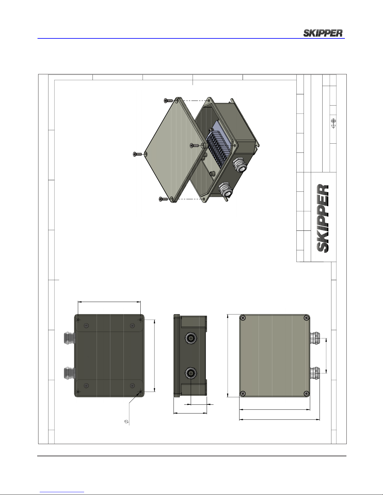
2018-05-28
Page 53 of 60
Installation DL2 Doppler Speed Log System
66
31,5
165,5
141
161
70
125
144
6,1 (4x)
Approved by - date
HK 2012.02.09
Designed by - date
1 of 1
JB12 Outline Drawing
Scale
OD-JB12
Revision
X0
Sheet
Edition date
Name
Drwg. no.
CN
Checked by
Material
Eur. projection
Gen. tolerance
1:2
ISO2768m
E
Electronics AS
B
A
8
7
6
4
D
C
5
2
3
4
3
2
Junction box JB12 Dimentional drawings
Page 54
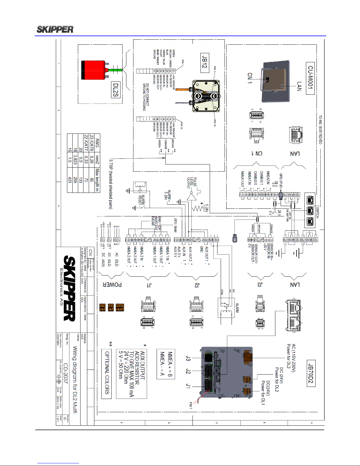
Page 54 of 60
2018-05-28
Installation DL2 Doppler Speed Log System
Page 55
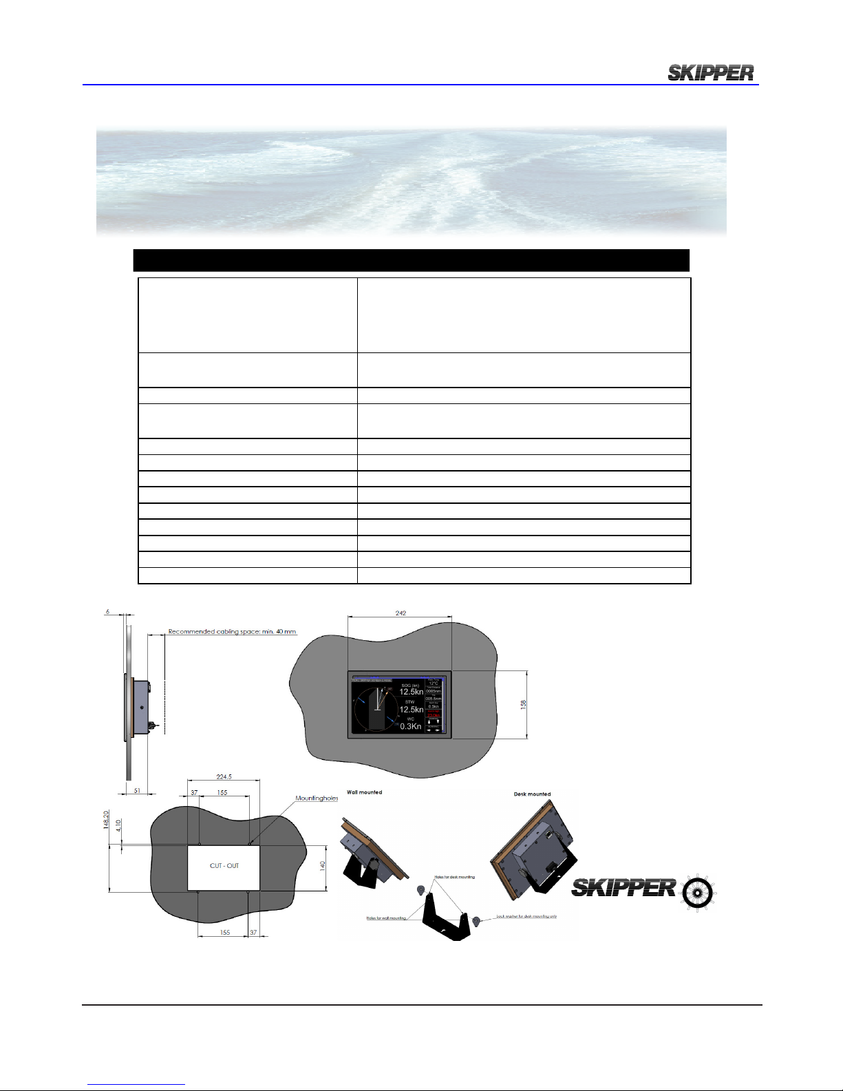
2018-05-28
Page 55 of 60
Installation DL2 Doppler Speed Log System
APPENDIX 2: DATA SHEETS
Description
Multi - PanelPC 9inch touch display
9” Touch display. Resistive touch,
Resolution 800 x 480.
LED backlight. 400 Nits.
Viewing angle 70/70/50/60 degrees
Night dimming via touch or NMEA
Flush mount, wall mount or desktop mount
Input/Output
1 LAN. IEC 61162-450
2 NMEA in. 1 NMEA out. NMEA 0183, IEC61162-1/2
(2 CAN, future option)
Used with
JB70XX-XX Electronic unit
Package consist of
9” Control unit
Bracket for desk/wallmount
Connector female, Power, NMEA, CAN
Mounting options
Flush/wall/desk
Packaging dimensions
325 x 125 x 230 mm
Packaging weight
1,2 kg
Power consumption
12 - 24 V DC, max 10 W, typ 6 W
IP rating
22
Operating temperature
-15 to 55
°C
Storage temperature
-20 to 70
°C
Humidity
10 to 90% relative. No condensation
Manufacturer
SKIPPER Electronics AS, Norway
Specications
Product Datasheet
CU-M001-SA Multi - PanelPC 9inch touch display
Dimensions in mm
All product specications are subject to change without notice
SKIPPER Electronics AS
Enebakkveien 150
P.O.Box 151, Manglerud
0612 Oslo, Norway
E-mail: [email protected]
Telephone: +47 23 30 22 70
Telefax: +47 23 30 22 71
Co.reg.no: NO-965378847 - MVA
www.skipper.no
Date: 2015.01.13
Page 56
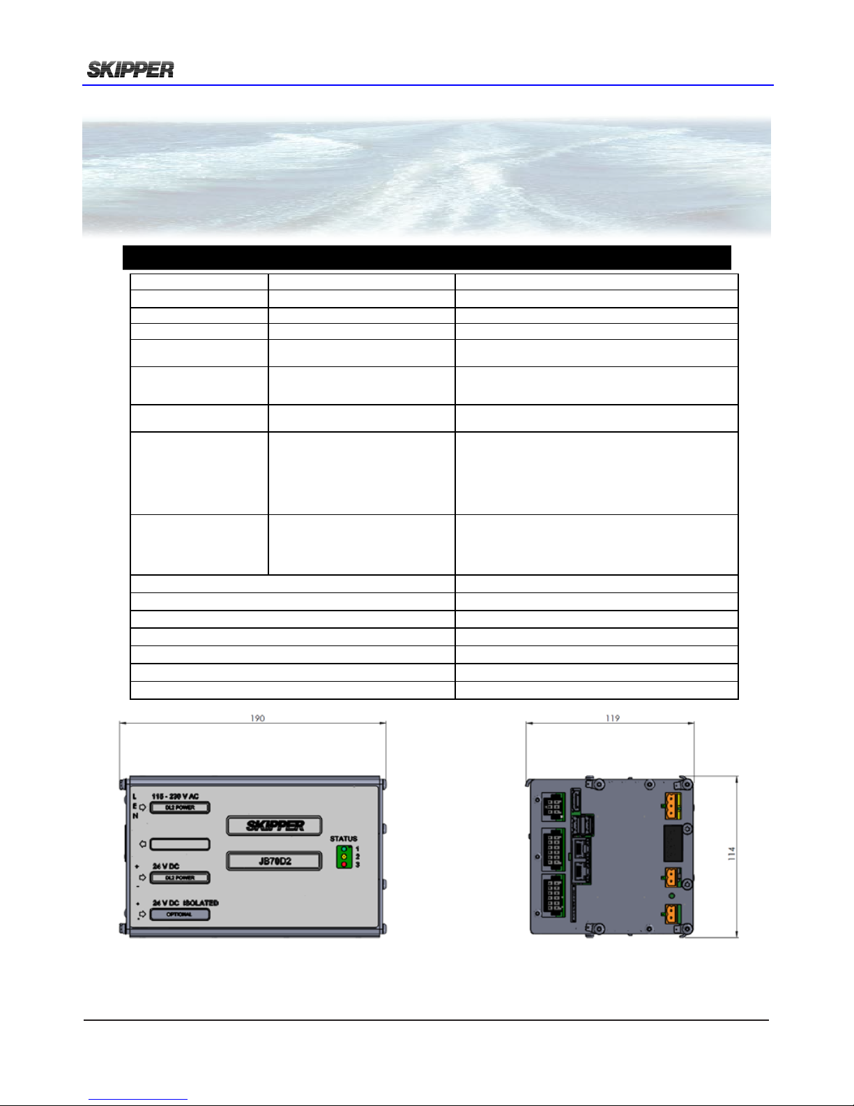
Page 56 of 60
2018-05-28
Installation DL2 Doppler Speed Log System
Data sheet JB70D2-SA
Part number Description
Part number JB70D2-SA Electronic Unit for DL2
Control units CU-M001-XX Control Unit 9” Touch display
Sensors DL2SXX 2-axis STW+SOG
Package consist of JB70D2-SA
M-KIT-JB70D2
Electronic Unit for DL2
Mounting Kit for JB70D2
PCBs inside
Electronic unit
PP-M001
PC-M001
PI-M001 (Optional)
Multi Power, PCBM
Multi Main Processor, PCBM
I/O Multi extension, PCBM (Optional for extra NMEA + analog out)
Power Input 115-230 VAC and/or 24VDC Max 60W typ.
15W
Standard In/out 4 x NMEA 0183,IEC61162-1 output
2 x NMEA 0183,IEC61162-1 input
2 x Auxiliary output
1 x Auxiliary input
1 x Auxiliary (relay)
2 x LAN IEC 61162-450
web page setup
NMEA outputs can be used for IEC61162-2
Auxiliary output can be designated to alarm, pulse, spd warning
Auxiliary input can be designated to alarm or dimming control
relay designated to function and/or powerfailure alarm
Congurable web pages for setup and runtime functions
Optional In/Out 4 x NMEA out 0183, IEC 61162-1 output
2 x analogue 0-10V, or 4-20mA
4 x Auxiliary output
2 x Auxiliary input
Optional PCB PI-M001
for extra NMEA outputs and Analog outputs.
Auxiliary output can be designated to alarm, pulse, spd warning
Auxiliary input can be designated to alarm or dimming control
IP rating IP 22 (when mounted with PCBs vertical)
Operating temperature
-15 to 55
°C
Storage temperature
-20 to 70
°C
Humidity 10 to 90% relative. No condensation
Weight 1.5 kg
Packaging dimensions / weight 30.5x21.5x21cm / 2 kg
Manufacturer SKIPPER Electronics AS, Norway
Specications
Product Datasheet
JB70D2-SA Electronic unit for
SKIPPER Doppler Speed Log DL2
Dimensions in mm
Page 57
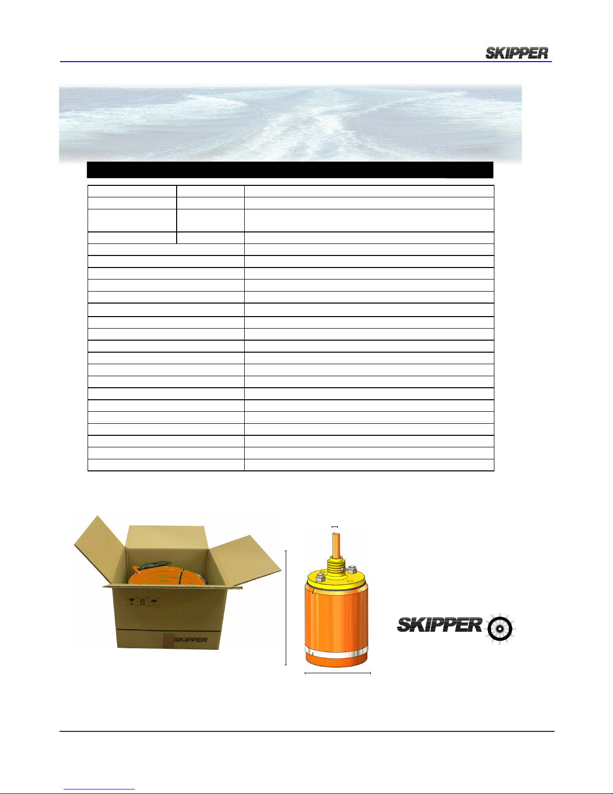
2018-05-28
Page 57 of 60
Installation DL2 Doppler Speed Log System
Data sheet DL2SG-SA
Part number Description
DL2SG-SA Log sensor DL2 SKIPPER for 100 mm Sea Valve
To be installed into SB-100-XX
DB-100-XX
Sea valve 100 mm for single bottom hull
Sea valve 100 mm for double bottom hull
To be used with JB70D2-XX Electronic Unit for DL2 Dual Axis Doppler Speed Log
Acoustic frequency range 270-284 kHz
Bottom detection (SOG) <200 m
Cable length 40 m (may be extended or shortened. Recommended CAT6 cable)
Cable diameter
11 mm +/-0.5
Cable minimum bending radius
56 mm
Accuracy 0.2 kn or 2 % whichever is greater
Speed resolution 0.1 kn
Max speed +/- 50 kn
Temperature accuracy 1 deg
Temperature resolution 0.1 deg
IP rating IP 68
Depth rating 6 bar
Operating temperature -15 to 55°C
Storage temperature -20 to 70°C
Outputs 1 x NMEA (Proprietary formats) RS422
Input 1 x NMEA (Proprietary formats) RS422
Power input Nom. 24 V (18 V to 32 V) 16 W
Weight 10.2 kg
Manufacturer SKIPPER Electronics AS, Norway
Spesications
45cm * 44cm * 32 cm
10.2kg
Product Datasheet
DL2SG-SA Log sensor DL2 SKIPPER for
100 mm Sea Valve
ø 100 mm
137 mm
ø 11 mm
125.3 mm
All product specications are subject to change without notice
SKIPPER Electronics AS
Enebakkveien 150
P.O.Box 151, Manglerud
0612 Oslo, Norway
E-mail: [email protected]
Telephone: +47 23 30 22 70
Telefax: +47 23 30 22 71
Co.reg.no: NO-965378847 - MVA
www.skipper.no
Date: January 2015
Version: 07012015
Page 58

Page 58 of 60
2018-05-28
Installation DL2 Doppler Speed Log System
This page is left intentionally blank
Page 59
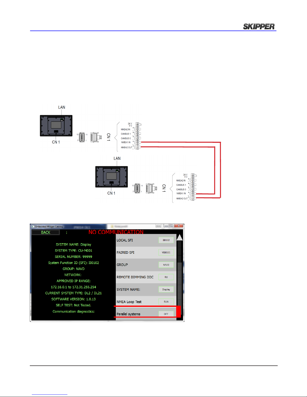
2018-05-28
Page 59 of 60
Installation DL2 Doppler Speed Log System
APPENDIX 4: CONNECTING 2 SYSTEMS
Some vessels require 2 systems connected together. It is currently not possible to have both systems
running at the same time, however it is possible to get the systems to connect together such that both
are powered, and by setting one unit in standby (Cong menu) The other will wake up by itself.
To implement this the NMEA output of a CU-M001 graphic display on one system, must be connected
to the input of the display of the other system. i.e cross over of NMEA.(pin 9-11, 10-12)
In addition the option ‘Parallel systems’ must be turned to ‘ON’ on the screens with NMEA connection.
In this mode all system parts will be powered. and when one system is placed in standby will be muted, and all IO will sleep. When it is woken ( by touching the screen) it will command the other unit to
go into standby. THis reduces the time of changeover to a few seconds
Page 60
SKIPPER Electronics AS Telephone: +47 23 30 22 70
Enebakkveien 150 www.skipper.no
P. O. Box 151, Manglerud E-mail: [email protected]
0612 Oslo, Norway Co. reg. no: NO-965378847-MVA
APPENDIX 4: COMMISIONING CHECKLIST
Test Nr Task Test to be performed Checklist
DL2 – 1
DL2 – 2
DL2 - 3
Wire and check the
system
Wire together the JB70 LAN and
CU-M001 Graphic display
• Display does not show ‘NO
COMMUNICATION’
Set up the cong as per instructions
Wire NMEA IN, NMEA OUT
• MFD shows VBW,x.x,y.y,A,x
.x,y.y,A,,A,z.z,A , MTW, VLW
Wire Relay output J2 to common
alarm
• Remove power (AC and
DC) and check you see alarm
DL2 – 4
DL2 – 5
DL2 – 6
Install and connect
sensor for DL2 to the
JB70 unit (J3)
Connect JB70 to CUM001 display
Check Sensor
Check Using the service software
and the self test in Cong – Diagnostic – Self test,
• Serial Number of sensor
(DL2) should be same as on cable
• Firmware version should be
correct (3.00 or greater)
• Live data should show quality factor (QF) 8 or 9
Upgrade rmware to the version on
the skipper websites
DL2 – 9
DL2 - 10
Install setup in the
Bridge Conning system
Check on MFD that you see inputs
from DL2
• You can see input VBW,
VLW, MTW, occasional VDALR,
Check on MFD that you can see
the Outputs to the Log
• You can see VTG, DPT,
GGA, occasional ACK
DL2 – 11
DL2-12
Check NMEA 1/2 input
Check on display – Cong – Communication, that the input is showing GYRO and GPS information.
• Can see HDT/THS, ROT,
VTG,GGA/GLL
• Can see aft speed on page
D
 Loading...