

Page 1
Operating/Safety Instructions
Consignes de fonctionnement/
sécurité
Instrucciones de funcionamiento
y seguridad
RAS800
IMPORTANT:
Read Before Using
IMPORTANT :
Lire avant usage
IMPORTANTE:
Leer antes de usar
For English
See page 2
Parlez-vous français?
Voir page 29
¿Habla español?
Ver página 57
Consumer Information
Renseignement des consommateurs
Información para el consumidor
Toll-Free Number: Appel gratuit : Número de teléfono gratuito:
1-877-SKIL999 (1-877-754-5999) http://www.skil.com
Page 2

2
Table of Contents
IMPORTANT SAFETY
INFORMATION . . . . . . . . . . . . . . . . . . .2–6
Parts List . . . . . . . . . . . . . . . . . . . . . . . 7–9
Router Table Setup . . . . . . . . . . . . . 10–15
Router Table Operation. . . . . . . . . . 16–28
Power Tool Safety Rules
Work Area
Keep your work area clean and well lit. Cluttered
benches and dark areas invite accidents.
Do not operate power tools in explosive
atmospheres, such as in the presence of
flammable liquids, gases, or dust. Power tools
create sparks which may ignite the dust or fumes.
Keep bystanders, children, and visitors away
while operating a power tool. Distractions can
cause you to lose control.
Electrical Safety
Grounded tools must be plugged into an outlet
properly installed and grounded in accordance
with all codes and ordinances. Never remove
the grounding prong or modify the plug in any
way. Do not use any adaptor plugs. Check with
a qualified electrician if you are in doubt as to
whether the outlet is properly grounded. If the
tools should electrically malfunction or break down,
grounding provides a low resistance path to carry
electricity away from the user. Improper grounding
can shock, burn, or electrocute. Grounded tools
are equipped with three-conductor cord and threeprong-type plugs. Before plugging in the tool, be
certain the outlet voltage supplied is within the
voltage marked on the nameplate. Do not use
“AC only” rated tools with a DC power supply.
Double-insulated tools are equipped with a
polarized plug (one blade is wider than the
other). This plug will fit in a polarized outlet
only one way. If the plug does not fit fully in
the outlet, reverse the plug. If it still does not
fit, contact a qualified electrician to install a
polarized outlet. Do not change the plug in any
way. Double Insulation eliminates the need for
the three-wire grounded power cord and grounded
power supply system. Before plugging in the tool,
be certain the outlet voltage supplied is within the
voltage marked on the nameplate. Do not use “AC
only” rated tools with a DC power supply.
Avoid body contact with grounded surfaces
such as pipes, radiators, ranges, and
refrigerators. There is an increased risk of electric
shock if your body is grounded. If operating the
power tool in damp locations is unavoidable, a
Ground Fault Circuit Interrupter must be used to
supply the power to your tool. Electriciansʼ rubber
gloves and footwear will further enhance your
personal safety.
Donʼt expose power tools to rain or wet
conditions. Water entering a power tool will
increase the risk of electric shock.
Do not abuse the cord. Never use the cord to
carry the tools or pull the plug from an outlet.
Keep cord away from heat, oil, sharp edges,
or moving parts. Replace damaged cords
immediately. Damaged cords increase the risk
of electric shock.
When operating a power tool outside, use an
outdoor extension cord marked “W-A” or “W.”
These cords are rated for outdoor use and reduce
the risk of electric shock. Refer to “Important
Information About Extension Cords” in your router
table manual.
Read and understand the tool manual and these instructions for the
use of this table with your router. Failure to follow all instructions listed
below may result in serious personal injury.
SAVE THESE INSTRUCTIONS
Page 3

3
Personal Safety
Stay alert, watch what you are doing, and use
common sense when operating a power tool.
Do not use tool while tired or under the
influence of drugs, alcohol, or medication.
A moment of inattention while operating power
tools may result in serious personal injury.
Keep guards in place. Maintain the guards
in working order and in proper adjustment and
alignment.
Avoid accidental starting. Be sure switch is
“OFF” before plugging in. Carrying tools with
your finger on the switch or plugging in tools that
have the switch “ON” invites accidents.
Remove adjusting keys or wrenches before
turning the tool “ON.” A wrench or a key that is
left attached to a rotating part of the tool may result
in personal injury.
Do not overreach. Keep proper footing and
balance at all times. Proper footing and balance
enable better control of the tool in unexpected
situations.
Use safety goggles (head protection). Wear
safety goggles (must comply with ANSI Standard
Z87.1) at all times. Wear nonslip footwear and a
hard hat, if appropriate. Also, use face or dust mask
if cutting operation is dusty and ear protectors
(plugs or muffs) during extended periods of
operation.
Tool Use and Care
Use clamps or other practical way to
secure and support the workpiece to a
stable platform. Holding the work by hand
or against your body is unstable and may
lead to loss of control.
Do not force tool. Use the correct tool for
your application. The correct tool will do the
job better and safer at the rate for which it is
designed.
Do not use tool if switch does not turn
it “ON” or “OFF.” Any tool that cannot be
controlled with the switch is dangerous and
must be repaired.
Disconnect the plug from the power source
before making any adjustments, changing
accessories, or storing the tool. Such
preventive safety measures reduce the risk
of starting the tool accidentally.
Keep guards in place. Maintain the guards
in working order and in proper adjustment and
alignment.
Store idle tools out of reach of children
and other untrained persons. Tools are
dangerous in the hands of untrained users.
Never leave tools running unattended.
Turn the power “OFF.” DO NOT leave tool
until it comes to a complete stop.
Maintain tools with care. Keep cutting tools
sharp and clean. Properly maintained tools,
with sharp cutting edges, are less likely to
bind and are easier to control. Any alteration
or modification is a misuse and may result in
a dangerous condition.
Check for damaged guards or parts,
misalignment or binding of moving parts,
breakage of parts, and any other condition
that may affect the toolʼs operation. If
damaged, have the tool properly repaired
or replaced before using. Many accidents
are caused by poorly maintained tools.
Develop a periodic maintenance schedule
for your tool.
Use only accessories that are
recommended by the manufacturer for
your model. Accessories that may be suitable
for one tool may become hazardous when
used on another tool.
Service
Tool service must be performed only
by qualified repair personnel. Service
or maintenance performed by unqualified
personnel could result in a risk of injury. For
example, internal wires may be misplaced or
pinched, or safety guard return springs may
be improperly mounted.
When servicing a tool, use only identical
replacement parts. Use of unauthorized parts
or failure to follow maintenance instructions
may create a risk of electric shock or injury.
Certain cleaning agents such as gasoline,
carbon tetrachloride, and ammonia may
damage plastic parts.
Additional Safety Warnings for Router Tables
Lift router table only by the table edges.
Lifting table by any other surface could cause
personal injury.
Always rotate leg assembly from end of leg
and keep fingers clear of joint. This avoids a
pinch point.
Never rotate leg assemblies until they are
in the unlocked position. This will prevent
possible damage to the legs or table housings.
Broken legs or table housings may allow the
table to collapse.
Do not use the router table until all
assembly and installation steps have been
completed. Prior to each use, verify that
fasteners and the router clamps are tight. A
loose table or router is unstable and may shift
in use, resulting in property damage or serious
personal injury.
Before operating the router in the router
table, ensure that the table legs are fully
extended, in the locked position, and the
entire unit (router table with router) is
placed on and secured to a solid, flat, level
surface that will not tip. Such precautionary
safety measures reduce the risk of the table
Page 4

4
Additional Safety Warnings for Router Tables
shifting unexpectedly while in use, resulting in
property damage or serious personal injury.
Disconnect the router from the power
supply before installing router into the
table, making adjustments, changing
accessories, removing the router from the
table, performing maintenance, or storing
the tool. Such precautionary safety measures
reduce the risk of unintentional tool operation.
Do not plug router motor power cord into
standard wall outlet. Always plug router
cord into the router table switch box. Power
tool switches and controls need to be within
your reach in emergency situations.
Do not permit fingers to touch terminals on
the plug when inserting or removing plug
from the outlet.
Before connecting router or vacuum to
router table switch box, ensure that the
router or vacuum switch is off and that the
router table switch box is unplugged. Such
precautionary safety measures reduce the risk
of unintentional tool operation.
Before using the router table, verify that
the router is securely clamped in the router
table base. While working, periodically
check the router base fastener clamping
tightness. Vibrations from cutting operations
can cause router motor clamps to loosen and
the router motor may fall from the table.
Before starting to work, ensure that the
power cords from the router accessories,
the switch box, and the extension cord do
not and cannot come in contact with the
router or any moving parts of the router.
Such precautionary safety measures reduce
the risk of injury due to loss of control.
Do not use the router table without the
overhead guard unless required by a
particular cutting operation. Replace guard
immediately after completion of cutting
operation. Remove all dust, chips, and any
other foreign particles that can affect its
function. The guard will aid in keeping hands
from unintended contact with the rotating bit.
Do not use bits that have a cutting
diameter that exceeds the clearance hole
in the tabletop insert plate or insert rings.
Bit could contact insert plate or insert ring,
throwing fragments.
Never use dull or damaged bits. Damaged
bits can snap during use. Dull bits require
more force to push the workpiece, possibly
causing the bit to break or the material to
kick back.
Handle sharp bits with care. Such precautionary safety measures reduce risk of injury.
Do not alter insert ring or insert plate bit
hole. Match the cutting diameter of the
bit to the inner diameter of the insert ring
or insert plate bit hole such that the
difference is no less than 1/16" on a side.
Insert rings are meant to reduce the gap
between the cutting diameter of the bit and the
table so that workpieces maintain full support
of the table while routing.
Install bit in accordance with instructions
in the router manual. Securely clamp the
router bit in the collet chuck before making
any cuts. Securing the bit before cutting
reduces the risk of the bit becoming loose
during operation.
Never place your fingers near a spinning
bit or under the guard when the router is
plugged in. Such precautionary safety
measures reduce the risk of injury.
Never hold the workpiece on the outfeed
side of the bit. Pressing the workpiece
against the outfeed side of the fence may
cause material binding and possible kickback,
pulling your hand into the bit.
Guide the workpiece with the fence to
maintain control of the workpiece. Do not
place the workpiece between router bit
and fence while routing the edge. This
placement will cause the material to become
wedged, making kickback possible.
Only use routers for working with wood,
woodlike products, plastic, or laminates.
Do not use router and router table for
cutting or shaping metals. Be sure
workpiece does not contain nails or other
hard objects. Cutting nails may cause loss
of control of the tool or workpiece.
Never start the tool when the bit is
engaged in the material. The bit-cutting edge
may grab the material, causing loss of control
of the workpiece.
Feed the workpiece only against the
rotation of the bit. Do not “back feed” the
workpiece into the bit. The bit rotates
counterclockwise as viewed from the top of
the table. “Back feeding” will cause the
workpiece to “climb” up on the bit, pulling the
workpiece and possibly your hands into the
rotating bit.
Do not feed the workpiece into the bit
where the majority of the workpiece is
between the fence and the bit. This creates
a “fence trap” which is a hazardous situation
due to the bit being exposed. This will cause
the work to “climb-cut” away from the tabletop
and may lead to loss of control during
operation.
Do not cut material that is warped, wobbly,
or otherwise unstable. The router table is
designed to cut flat, straight, and squared
materials. If the material is slightly curved
but otherwise stable, cut the material with
the concave side against the table or fence.
Cutting the material with the concave side up
or away from the table may cause the warped
or wobbly material to roll and kick back,
causing the user to lose control.
Page 5
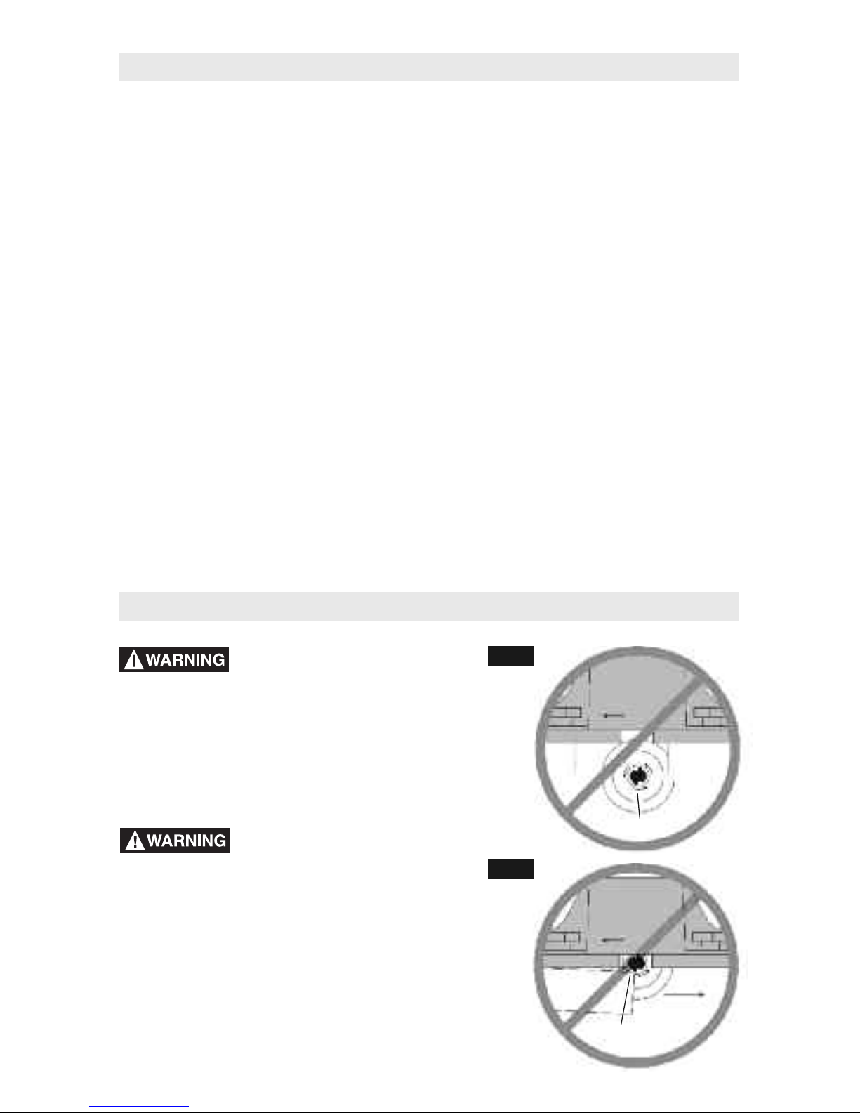
Improper Fence Location and Workpiece Feed
Do not feed the workpiece where
the majority of the workpiece is
between the fence and the bit. This creates a “fence
trap” which is dangerous for two reasons:
•
The front of the bit is exposed during the cutting
operation (Fig. A).
•
The bit can “Climb-cut,” where the bit enters the
workpiece in the same direction as the feed
direction. This is likely to cause the workpiece to
“climb” away from the tabletop and may lead to loss
of control during operation (Fig. A).
Feed the workpiece only against
the rotation of the bit. Do not
“back feed” the work into the bit. The bit rotates
counterclockwise as viewed from the top of the table.
“Back feeding” the work is dangerous for two reasons:
•
It will cause climb-cutting where the workpiece can
“climb” off the tabletop in the direction of the bit
rotation, pulling the workpiece and possibly your
hands into the rotating bit (Fig. B).
•
It is difficult to keep the workpiece against the fence
face as the bit rotation will push the workpiece away
from the fence.
FIG. A
FIG. B
WORKPIECE
EXPOSED BIT
WORKPIECE
CLIMB-CUTTING
DIRECTION
OF FEED
CORRECT
DIRECTION
OF FEED
INCORRECT
DIRECTION
Use auxiliary infeed and outfeed supports
for long or wide workpieces. Oversize
workpieces without adequate support can flip
off the table or cause the table to tip.
Use push stick, vertically and horizontally
mounted featherboards (spring sticks), and
other jigs to hold down the workpiece.
Push sticks, featherboards, and jigs eliminate
the need to hold the workpiece near the
spinning bit.
Never let go of the workpiece when routing
until the cut has been completed and the
workpiece is completely clear of the bit.
Such precautionary safety measures reduce
the risk of injury and property damage.
Featherboards aid in holding the workpiece in
position when routing on a router table. They
are not intended to hold the workpiece in place
alone when the workpiece is in contact with
the bit, or at any other time when the bit is
turning.
Always hold the workpiece against the
router table fence when routing. Such
precautionary measures increase accuracy in
routing and improve control of the workpiece,
reducing the risk of injury.
Never leave the router unattended while it
is running or before it comes to a complete
stop. Such precautionary safety measures
reduce the risk of injury and property damage.
Do not use the table as a workbench or
work surface. Using it for purposes other
than routing may cause damage and make it
unsafe to use in routing.
Never stand on the table or use as a ladder
or scaffolding. The table could tip or the
cutting tool could be accidentally contacted.
When servicing the tool, use only
recommended SKIL replacement parts.
Follow instructions in the Maintenance
section of this manual. Use of unauthorized
parts or failure to follow maintenance
instructions can result in personal injury.
Some dust created by power sanding,
sawing, grinding, drilling, and other
construction activities contains chemicals
known to cause cancer, birth defects, or
other reproductive harm. Some examples
of these chemicals are:
•
Lead from lead-based paints
•
Crystalline silica from bricks, cement,
and other masonry products
•
Arsenic and chromium from chemically
treated lumber
Your risk from these exposures varies,
depending on how often you do this type of
work. To reduce your exposure to these
chemicals, work in a well-ventilated area, and
work with approved safety equipment, such as
those dust masks that are specially designed
to filter out microscopic particles.
Additional Safety Warnings for Router Tables
5
Page 6
6
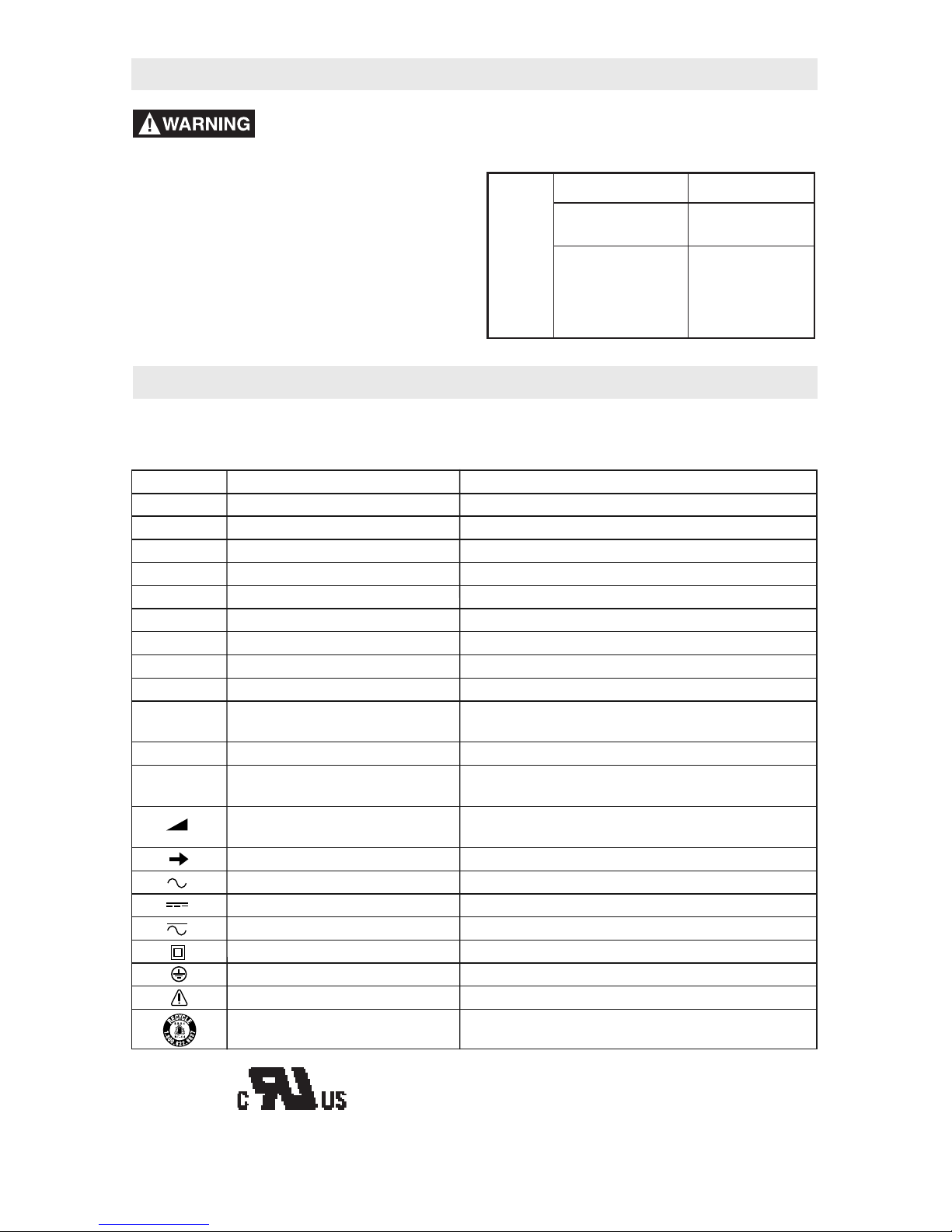
IMPORTANT: Some of the following symbols may be used on your tool. Please study them and
learn their meaning. Proper interpretation of these symbols will allow you to operate the tool
better and safer.
Symbol Name Designation/Explanation
V Volts Voltage (potential)
A Amperes Current
Hz Hertz Frequency (cycles per second)
W Watt Power
kg Kilograms Weight
min Minutes Time
s Seconds Time
Ø Diameter Size of drill bits, grinding wheels, etc.
n
0
No load speed Rotational speed, at no load
.../min Revolutions or reciprocation Revolutions, strokes, surface speed, orbits,
per minute etc., per minute
0 Off position Zero speed, zero torque...
1, 2, 3, ... Selector settings Speed, torque, or position settings
I, II, III, Higher number means greater speed
Infinitely variable selector Speed is increasing from 0 setting
with off
Arrow Action in the direction of arrow
Alternating current Type or a characteristic of current
Direct current Type or a characteristic of current
Alternating or direct current Type or a characteristic of current
Class II construction Designates double-insulated construction tools
Earthing terminal Grounding terminal
Warning symbol Alerts user to warning messages
Ni-Cad RBRC seal Designates Ni-Cad battery recycling program
Symbols
0
This symbol designates that components of this tool are
recognized by Underwriters Laboratories and recognized
to Canadian Standards by Underwriters Laboratories.
An extension cord with
adequate size conductors
that is capable of carrying the current for
your tool must be used. This will prevent
excessive voltage drop, loss of power, or
overheating. Grounded tools must use 3-wire
extension cords that have 3-prong plugs and
receptacles.
NOTE: The smaller the gauge number, the
heavier the cord.
RECOMMENDED SIZES OF EXTENSION
CORDS FOR 120-VOLT ALTERNATING
CURRENT TOOLS
Tool’s
Ampere
Rating
Cord Size in A.W.G.
Wire Sizes in mm
2
3-6
6
-8
8
-10
10-12
12-16
1
8 16 16 14 .75 .75 1.5 2.5
1
8 16 14 12 .75 1.0 2.5 4.0
18 16 14 12 .75 1.0 2.5 4.0
16 16 14 12 1.0 2.5 4.0 —
14 12 — — — — — —
2
5 50 100 150 15 30 60 120
Cord Length in Feet Cord Length in Meters
Important Information About Extension Cords
Page 7

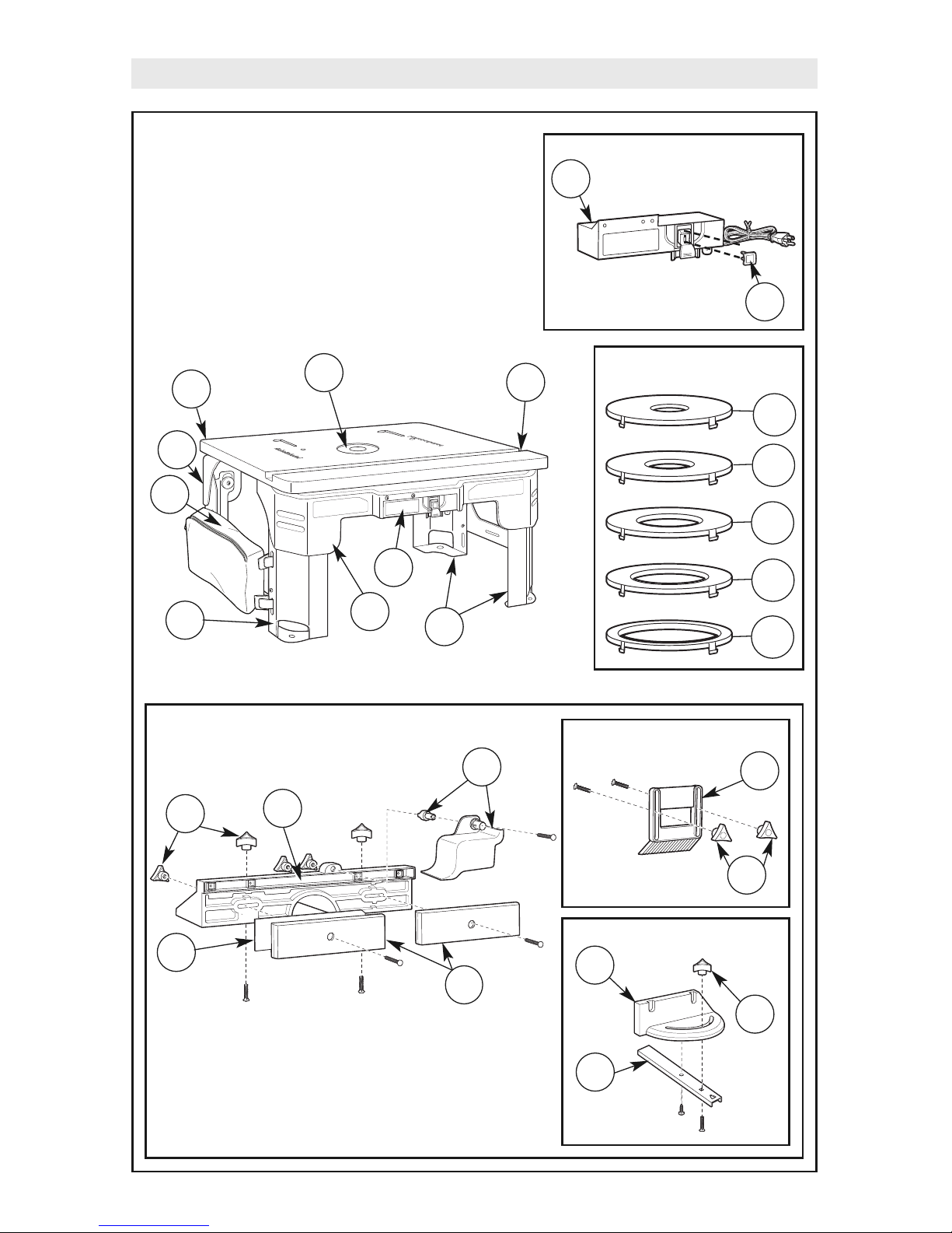
7
Parts List
•
If ANY of the parts are
missing, DO NOT attempt
to assemble, install, or use your router table
until the missing parts have been found or
replaced and your router table has been
properly and correctly assembled per this
manual.
•
For missing parts or technical assistance,
call 1-877-SKIL999 (877-754-5999).
•
In order to simplify handling and to minimize
any damage that may occur during shipping,
your router table comes mostly assembled.
Repositioning of some parts will be required.
•
Separate all parts from the packaging
materials and check each part against the
illustrations and the parts lists to make sure
that all parts have been included. Do this
before discarding any of the packaging
material.
Key No. Description Quantity
A ROUTER TABLE ASSEMBLY COMPONENTS
(shipped preassembled)
1 Router Tabletop 1
2 Insert Plate 1
3 Steel Miter Channel (includes 3 #10-32 x 7/8" screws, item 28) 1
4 Router Mounting Bracket (not shown) 4
5 Small Star Clamping Knob (not shown) 4
6 Front Table Housing 1
7 Rear Table Housing 1
8 Left Folding Steel Leg Assembly 1
9 Storage Bag 1
10 Right Folding Steel Leg Assembly 1
11 Insert Ring Set 1
11A Insert Ring w/ 1/2" dia. hole 1
11B Insert Ring w/ 3/4" dia. hole 1
11C Insert Ring w/ 1" dia. hole 1
11D Insert Ring w/ 1¼" dia. hole 1
11E Insert Ring w/ 1½" dia. hole 1
B SWITCH BOX ASSEMBLY COMPONENTS
12 Switch Box Assembly (with lockout key) 1
13 Lockout Key (replacement part) 1
C FENCE ASSEMBLY COMPONENTS
(shipped preassembled)
14 Router Table Fence 1
15
Overhead Guard Assembly (includes spacer)
1
16 Faceplate 2
17 Outfeed Shim Plate (may be attached to outfeed side of fence) 1
18 Clamping Knob 7
19 Featherboard 1
D MITER GAUGE ASSEMBLY COMPONENTS
20 Miter Bar 1
21 Protractor Head 1
22 Small Clamping Knob 1
ITEMS NOT ILLUSTRATED
23 Operating/Safety Instructions 1
Refer to Parts List below and on pages 8–9.
Page 8
8
Parts List
Insert Rings
1
11B
11A
7
3
6
8
10
13
12
Switch Assembly
11C
11D
11E
Table Assembly Components
B
9
Featherboard
19
18
Fence Components
18
16
15
14
Fence Components
21
20
22
Miter Gauge
17
2
Page 9
9
Parts List
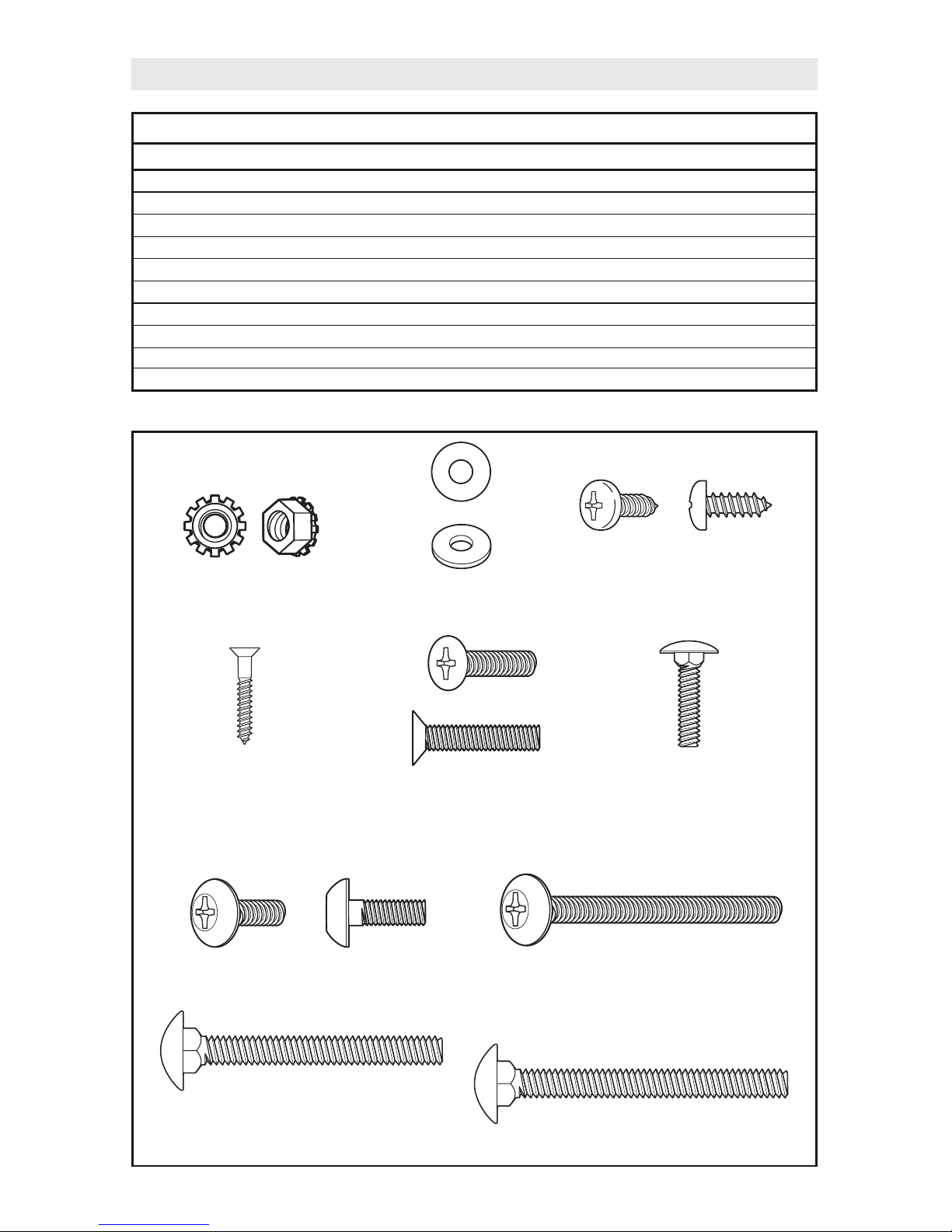
Key No. Description Quantity
MISCELLANEOUS FASTENERS (installed or bagged)
24 #10-32 KEPS Nut 13
25 #10-32 Flat Washer 4
26 #10-16 x 1/2" Pan-Head Self-Tapping Screw 5
27 #6 x 5/8" Flat-Head Wood Screw 2
28 #10-32 x 7/8" Countersunk-Head Screw 3
29 #10-24 x 3/4" Carriage Bolt 1
30 #10-32 x 5/8" Truss-Head Screw 17
31 #10-32 x 2½" Truss-Head Screw 4
32 1/4-20 x 1¾" Carriage Bolt 6
33 1/4-20 x 2½" Carriage Bolt 1
Miscellaneous Fasteners
(31) #10-32 x 2½"
Truss-Head Screw
(24) #10-32
KEPS Nut
(26) #10-16 x 1/2" Pan-Head
Self-Tapping Screw
(25) #10-32
Flat Washer
(27) #6 x 5/8"
Flat-Head Wood Screw
(28) #10-32 x 7/8"
Countersunk-Head Screw
(29) #10-24 x 3/4"
Carriage Bolt
(30) #10-32 x 5/8"
Truss-Head Screw
(32) 1/4-20 x 1¾" Carriage Bolt
(33) 1/4-20 x
2½" Carriage Bolt
Page 10
10
PREPARING THE ROUTER TABLE FOR USE
HELPFUL TOOLS TO HAVE ON HAND
•
#1 and #2 Phillips screwdrivers
(not included)
•
3/8" wrench or nut driver (not included)
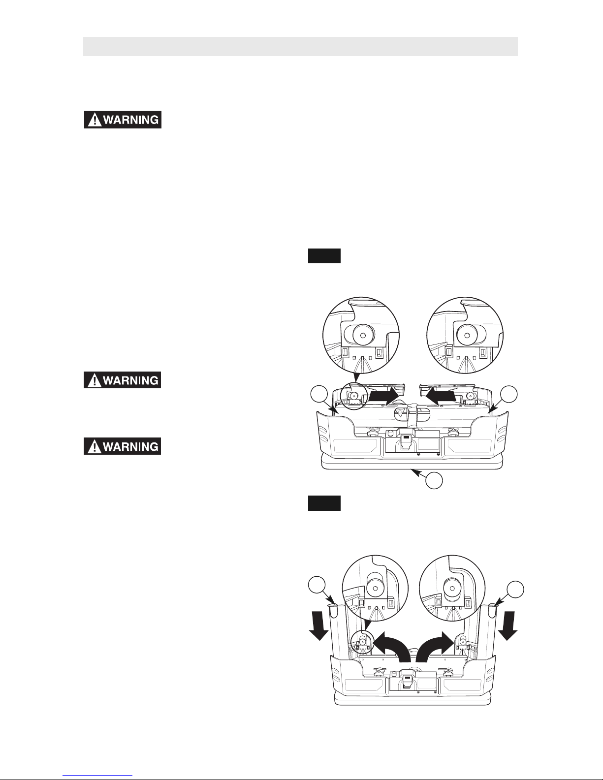
UNFOLDING AND LOCKING LEGS
(Figs. 1 and 2)
1. Gently lift and place the router table
assembly upside down on the tabletop (1).
2. Gently pull both leg assemblies (8 and 10)
inward towards center of the table until the
leg assemblies are in the unlocked position
as shown in Fig. 1.
Always rotate leg
assembly from end of leg
and keep fingers clear of joint. This avoids a
pinch point.
Never rotate leg
assemblies until the
locking tabs have been completely
disengaged. This will prevent possible
damage to the locking tabs or table housings.
3. After the leg assemblies (8 and 10) are
unlocked, rotate both leg assemblies to
the fully upright and extended position.
(See Fig. 2.)
4. Gently press down on both leg assemblies
(8 and 10) to secure and lock the left and
right leg assemblies in the upright position
as shown in Fig. 2.
Lift router table only by
the table edges. Lifting
table by any other surface could cause
personal injury.
Router Table Setup
8
10
1
FIG. 1
FIG. 2
8
10
LOCKED
(LEGS SLID
TOWARDS
OUTSIDE)
UNLOCKED
(LEGS SLID
TOWARDS
CENTER)
LOCKEDLOCKED
(LEGS SLID DOWN
TOWARDS TABLE)
UNLOCKED
(LEGS SLID UP
AWAY FROM TABLE)
Page 11
11
REMOVING THE FENCE ASSEMBLY
(Fig. 3)
The fence for your router table comes fully
assembled with the adjustable jointing fence
and overhead guard already in place. The fence
assembly is secured to the bottom of the table
for shipment and storage.
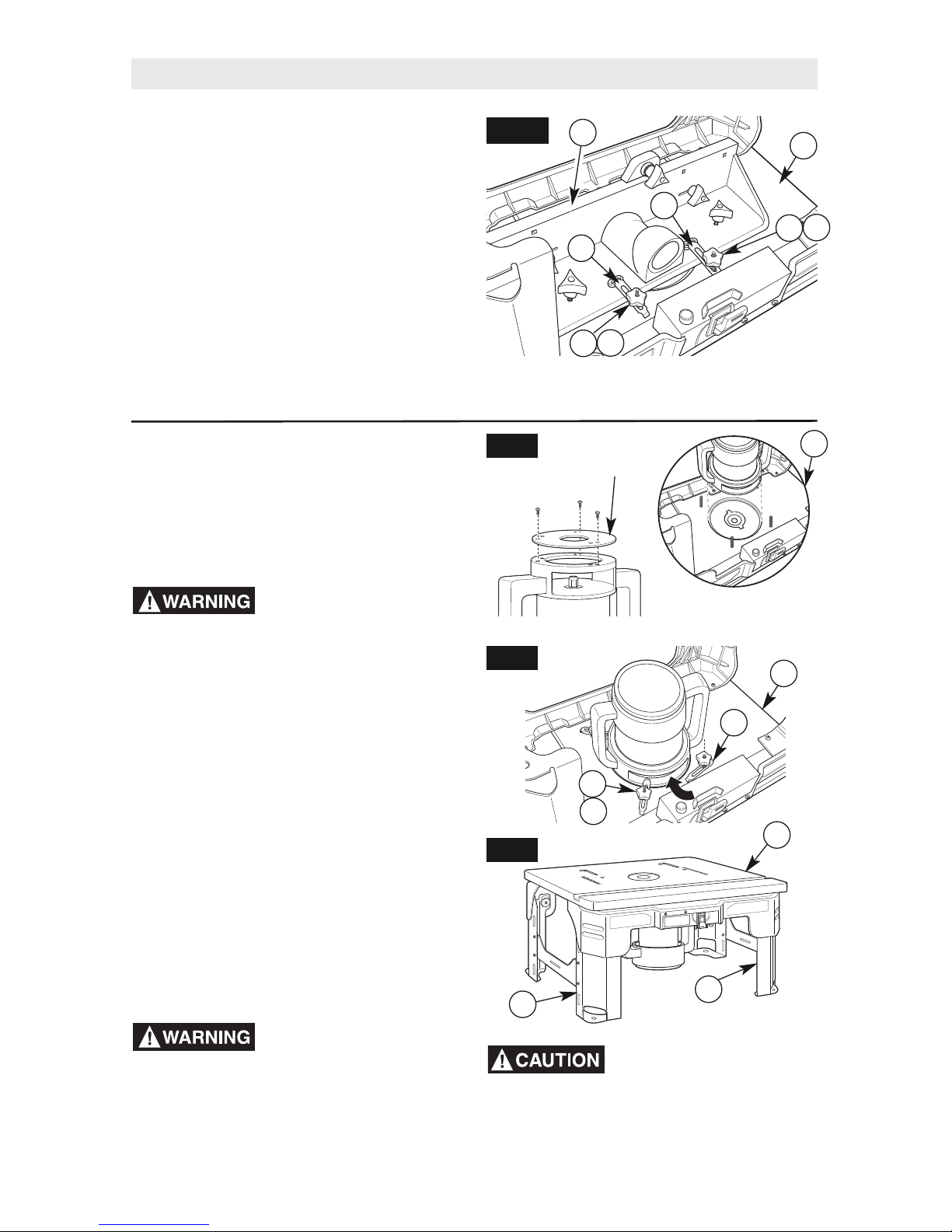
1. Loosen two small clamping knobs (5),
washers (25), and mounting brackets (4)
securing fence assembly (C) to bottom of
router table (1). Remove fence assembly
(C) from storage position under the router
table (1) and set it to one side. (See Fig. 3.)
1
C
5
4
Router Table Setup
FIG. 3
5
4
MOUNTING THE ROUTER TO THE
ROUTER TABLE (Figs. 4–6)
The bottom of the router table has two countersunk guide holes cut into the bottom of the table
to fit most standard 6" or 6½" router bases. Use
these as guides to center your router on the table.
Disconnect the router from
the power supply before
installing router into the table. Such
precautionary safety measures reduce the risk of
unintentional tool operation.
1. Gently turn over the router table (A) and
place it on its top. Make sure the fence
assembly (C) has been removed from its
storage position.
2. Remove the plastic subbase from the router
(Fig. 4). Store the screws and the subbase in
a convenient place.
3. Place the router in the correct countersunk
hole as shown in Fig. 4. (Brackets are
removed for clarity.)
4. Mount the router by positioning the four
mounting brackets (4) over the edges of the
router housing and tightening the small star
clamping knobs (5) and washers (25) to
secure the router to the bottom of the table
(A). Make sure the clamping knobs have been
securely tightened. (See Fig. 5.)
Before using the router
table, verify that the router
is securely clamped in the router table base.
While working, periodically check the router
base fasteners clamping tightness. Router
motor vibration can loosen fasteners during
use, causing the router to fall from the table.
A
FIG. 4
4
25
A
FIG. 5
10
8
A
FIG. 6
6" Inner Hole
6
½" Outer Hole
NOTE: Shim plate can be stored on outfeed
side of the fence assembly.
25
25
5
Do not adjust #10-32 x
2½" Truss-Head screws.
Screws are preinstalled. Overtightening
screws will damage the tabletop.
5. Gently turn over router table (A) and place
on the legs (8 and 10). (See Fig. 6.) See
pages 12–14 for further instructions.
REMOVE
SUBBASE
Page 12
12
Router Table Setup
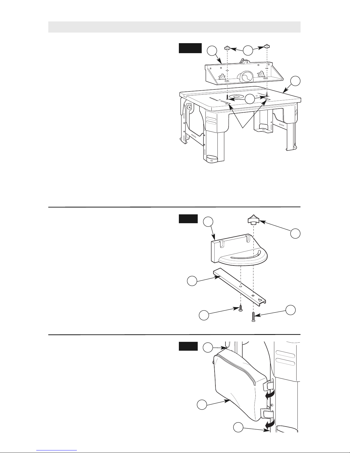
INSTALLING THE FENCE ASSEMBLY
(Fig. 7)
The fence comes assembled. Step 1 refers to
reassembly, if necessary; otherwise, go to Step 2
if already assembled.
1. From underneath, slide two 1/4-20 x 1¾"
carriage bolts (32) up through the holes in
the bottom of the fence assembly (C).
Loosely attach a clamping knob (18) onto
each bolt. (See Fig. 7.)
2. Insert the carriage bolt heads (32) through
the holes of the J-slots on the tabletop (1),
making sure the bolt heads are below the
inside surface of the tabletop and can slide
freely in the J-slot.
3. From the rear of the table assembly, slide the
fence assembly (C) right and into the J-slot
and make sure that it slides smoothly from
front to back.
4. Tighten the large clamping knobs (18) to
secure the fence assembly (C) to a desired
position.
1
C
18
32
FIG. 7
MITER GAUGE ASSEMBLY (Fig. 8)
The miter gauge assembly (D) comes fully
assembled. If necessary, use the following
instructions to assemble it.
1. Screw the #10-16 x 1/2" self-tapping,
pan-head screw (26) through the round
hole in the miter bar (20) and into the
protractor head (21).
2. Tighten the screw so that the screw head
just touches the miter bar. The protractor
head should turn easily. If not, loosen the
screw slightly.
3. Insert the #10-24 x 3/4" carriage bolt (29)
through the square hole in the miter bar
(20) and slot in the miter gauge and secure
with the small clamping knob (22).
22
29
20
21
FIG. 8
26
STORAGE BAG (Fig. 9)
A canvas storage bag (9) comes with the router
table (A). The storage bag can be mounted to
the outside or the inside of the left or right leg
assembly.
1. Pull apart each hook and loop strap
attached to the storage bag (9).
2. Feed each strap through the slots in the
left or right leg assembly (8 or 10).
3. Secure the storage bag (9) to the leg
assembly (8 or 10) by pressing each hook
and loop strap together.
FIG. 9
9
8
8
NOTE: Use the scale on the tabletop as a guide
when aligning the fence for routing operations.
Once the fence is positioned and aligned correctly,
tighten the clamping knobs SECURELY.
J-slot
Router removed for clarity
Page 13
13
Router Table Setup
MOUNTING THE ROUTER TABLE TO A
WORK SURFACE OR WORKBENCH
Before operating the
router in the router table,
ensure that the table legs are fully extended
and in the locked position. The entire unit
(router table with router) is placed on and
secured to a solid, flat, level surface that will
not tip. Such precautionary measures reduce
the risk of table shifting unexpectedly while in
use resulting in property damage or serious
personal injury.
HELPFUL TOOLS AND PARTS
(not included)
•
C-clamps
•
Phillips screwdrivers
•
Small adjustable wrench
•
Electric or hand drill with drill bits
(depending on mounting method used)
•
Fasteners
— 4 #10-16 x 3/4" pan-head wood screws
and 4 washers (for solid wood surfaces
or workbenches)
OR
— 4 3/16" pan-head machine screws,
8 washers, and 4 hex nuts
10
8
A
FIG. 10
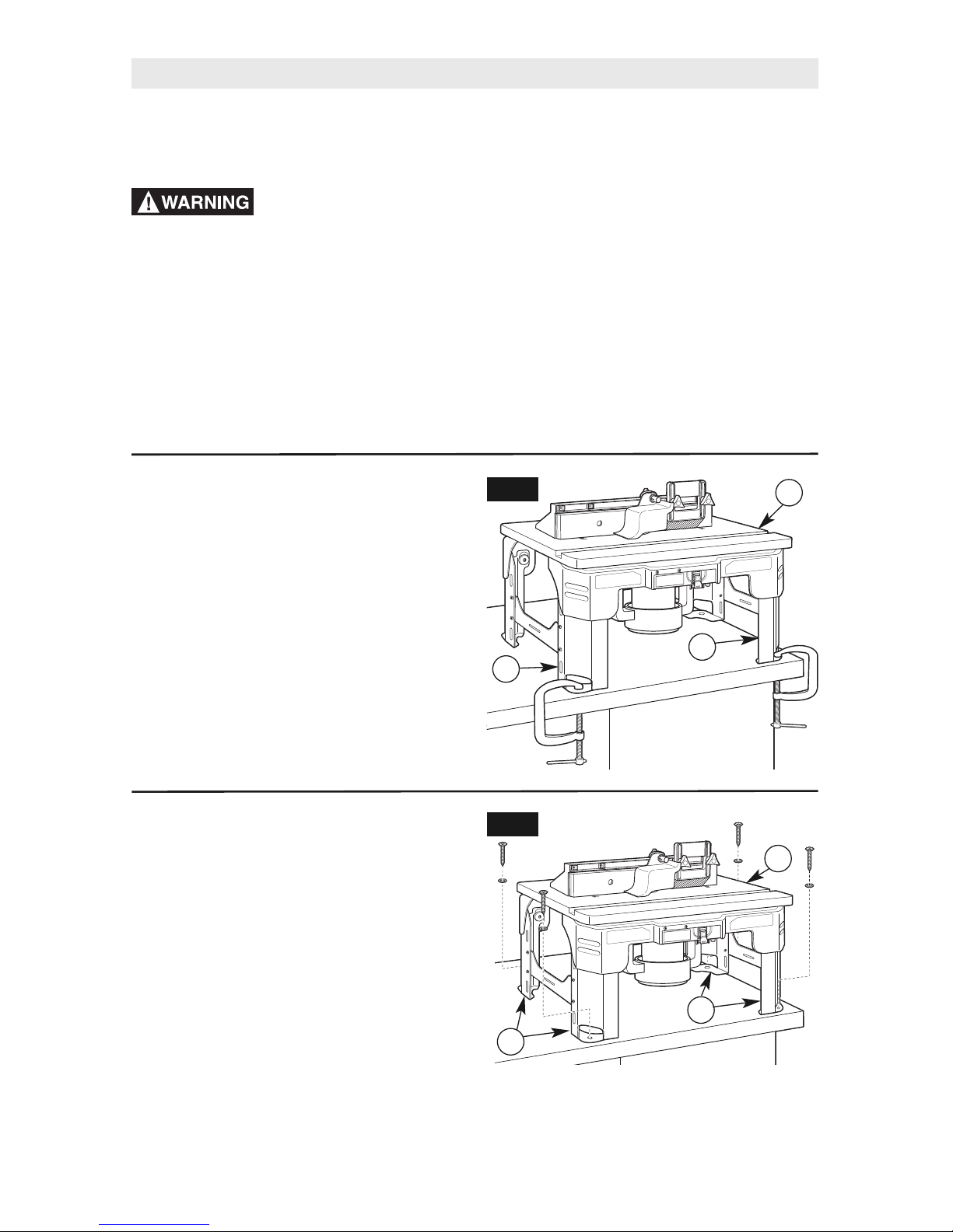
METHOD 1 (Fig. 10)
1. Set router table (A) on a workbench or other
stable surface, with the FRONT (switch side)
of the router table facing towards you.
2. Using the clamping bosses on the router table
legs (8 and 10), secure the router table legs to
the workbench with clamps. Be sure to tighten
them securely.
IMPORTANT: Be sure the placement of the
clamps will not interfere with operation of the
router table.
METHOD 2 (Fig. 11)
1. Set the router table (A) on a workbench or other
stable and sturdy surface, with the FRONT (switch
side) of the router table facing towards you.
2. While holding the router table in the desired
position, mark the location of the four mounting
holes (two on each leg assembly [8 and 10]).
3. Remove the router table (A) from the workbench
and set it aside.
4. Drill suitable pilot holes (for wood screws) or
through-holes (for machine screws) at the
marked locations.
5. Place the router table (A) on the workbench and
align the mounting holes in the router table legs
(8 and 10) with the holes drilled in the
workbench.
6. Secure the router table (A) in place using the
wood screws and washers (not provided).
10
8
A
FIG. 11
If using wood screws, applying a thin coat of
soap to the screw threads will make it easier to
thread the screws into the pilot holes.
7. TIGHTEN all screws SECURELY.
Page 14
14
Router Table Setup
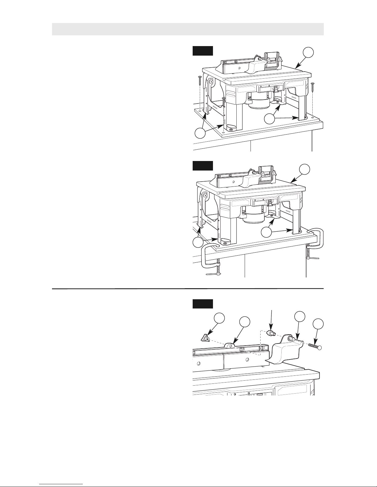
ALTERNATE METHOD 2
(Figs. 12 and 13)
1. Cut a board 181⁄4" wide x 23" long from
a piece of 3/4" thick wood or plywood.
2. Center the router table (A) on the board and
mark the location of the four mounting holes
(two on each leg assembly [8 and 10]).
3. Remove the router table (A) from the
workbench and set it aside.
4. Drill suitable pilot holes (for wood screws)
or through-holes (for machine screws) at
the marked locations.
5. Place the router table (A) on the board and
align the mounting holes in the router table
legs (8 and 10) with the holes drilled in the
board.
6. Secure the router table (A) in place
using the wood screws and washers (not
provided). Applying a thin coat of soap to
the screw threads will make it easier to
thread the screws into the pilot holes.
7. Secure the board to a workbench or other
sturdy surface with screws (Fig. 12) or
clamps (Fig. 13) during use.
IMPORTANT: Be sure the placement of
the clamps will not interfere with operation
of the router table.
10
8
A
FIG. 12
FIG. 13
10
8
A
OVERHEAD GUARD ASSEMBLY
(Fig. 14)
The overhead guard assembly (15) comes
preinstalled on the fence assembly. Some
routing applications will require you to remove
this guard.
1. Loosen and remove clamping knob (18) on
the top back of the fence assembly (C).
2. Slide the 1/4-20 x 2½" carriage bolt (33),
overhead guard (15), and spacer from
the fence assembly (C).
3. Reinstall the overhead guard assembly (15)
by following these steps in reverse.
FIG. 14
18
C
15
33
Spacer
Page 15
15
Disconnect the router
from the power supply
before installing router into the table,
making adjustments, changing
accessories, removing the router from
the table, performing maintenance,
or storing the tool. Such precautionary
safety measures reduce the risk of
unintentional tool operation.
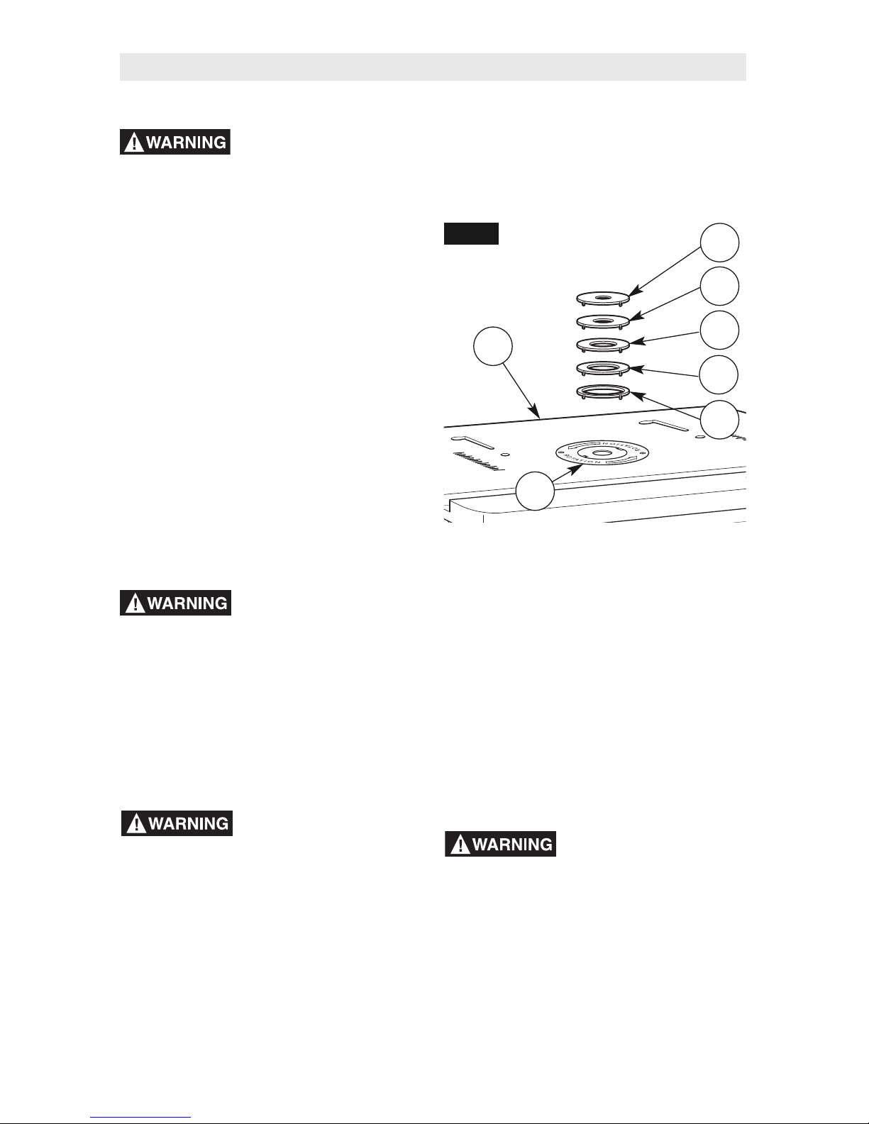
INSERT RINGS (Fig. 15)
This router table (1) includes five insert rings
with the following hole sizes:
(11A) 1/2" diameter, for use with bits up to
3/8" diameter
(11B) 3/4" diameter, for use with bits larger
than 3/8" and up to 5/8" diameter
(11C) 1" diameter, for use with bits larger
than 5/8" and up to 7/8" diameter
(11D) 1¼" diameter, for use with bits larger
than 7/8" and up to 11⁄8" diameter
(11E) 1½" diameter, for use with bits larger
than 11⁄8" and up to 13⁄8" diameter
No insert ring is required for bits with
diameters between 1½" and 15⁄8".
Do not use the router
table with bits over 15⁄8"
in diameter. Bits larger than 15⁄8" exceed
the clearance hole in the tabletop insert
rings. Bits larger than 15⁄8" can contact insert
plate or insert ring, throwing fragments.
These five insert rings are supplied individually
and can be found in the storage bag. The insert
ring should fit into the tabletop hole completely.
Use a fine file or emery board to remove excess
plastic or rough edges that may cause the insert
ring to protrude above the table surface.
Do not alter insert ring or
insert plate bit hole.
Match the cutting diameter of the bit to the
inner diameter of the insert ring or insert
plate bit hole such that the difference is no
less than 1/16" on a side. Insert rings are
meant to reduce the gap between the cutting
diameter of the bit and table so that
workpieces maintain full support of the table
while routing.
Router Table Setup
FIG. 15
11B
11C
11D
11E
11A
1
2
TO INSTALL TABLETOP
INSERT RINGS (Fig. 15)
1. Select the insert ring (11A–11E) that best
accommodates the router bit to be used.
2. Press the insert ring (11A–11E) into
the large hole in the plastic insert plate (2).
3. Press down evenly over the tabs until
the insert ring locks into place.
4. To remove, pull up gently until the tabs
disengage. When not in use, store insert
rings (11A–11E) in the tool bag or a
convenient place.
Do not use, attempt to
change, or remove
tabletop insert ring from the tabletop
unless the router is off and unplugged.
Such precautionary safety measures reduce
the isk of unintentional tool operation.
Page 16

16
Do not plug router motor
power cord into standard
wall outlet. Always plug router cord into
the router table switch. Power tool switches
and controls need to be within your reach in
emergency situations.
GENERAL INFORMATION
The power switch is designed for use with
most SKIL Router Tables. It provides the
convenience of an ON (RESET)/OFF switch at
the front of the table, thus eliminating the need
to reach underneath the table to turn the
router ON and OFF.
The power switch also provides an optional
simultaneous ON/OFF control of an additional
accessory, such as a light, wet/dry vacuum.
The switch has an internal, resettable circuit
breaker to provide overload protection.
ELECTRICAL REQUIREMENTS
The switch box cord should only be plugged
into a 14-gauge (or heavier), three-wire
extension cord with a three-hole grounding
receptacle and three-prong grounding plug.
The extension cord must be plugged into a
matching outlet that has been installed by a
licensed electrician and grounded in
accordance with all local codes and
ordinances.
DAMAGED OR WORN EXTENSION CORDS
ARE NOT TO BE USED AND ARE TO BE
REPLACED IMMEDIATELY.
The electrical cord at the back of the switch
will accept three-hole extension cords.
The electrical receptacles at the back of
the switch will accept either three-prong or
two-prong plugs from a router or accessory.
In the event of a malfunction or breakdown,
grounding provides the path of least resistance
for electrical current in order to reduce the risk
of electrical shock. This switch box is equipped
with an electrical cord that has an equipmentgrounding connector and a grounding plug.
DO NOT modify the plug from the switch if it
does not plug into the extension cord. Obtain
an extension cord with the proper outlet.
SWITCH CONTROL BOX
Improper connection of the equipmentgrounding conductor can result in risk
of an electrical shock. The conductor with
insulation that has a green outer surface,
with or without yellow stripes, is the
equipment-grounding conductor.
DO NOT CONNECT THE EQUIPMENTGROUNDING CONDUCTOR TO A LIVE
TERMINAL.
Check with a licensed electrician if the
grounding instructions are not completely
understood or if there is doubt as to whether
the electrical outlet or extension cord is
properly grounded.
Do not permit fingers to
touch terminals of the
plug when inserting or removing the plug
from the outlet.
Use the switch box only
when properly
assembled to the router table. Use only
with a router that has also been properly
installed on a properly assembled router
table. Such precautionary safety measures
reduce the risk of injury due to loss of control.
Do not exceed a total
combined rating of 15
amps when connecting the router and any
accessories such as a light or wet/dry
vacuum. The switch has a rating of 15 amps.
Router Table Operation
Page 17
17
Router Table Operation
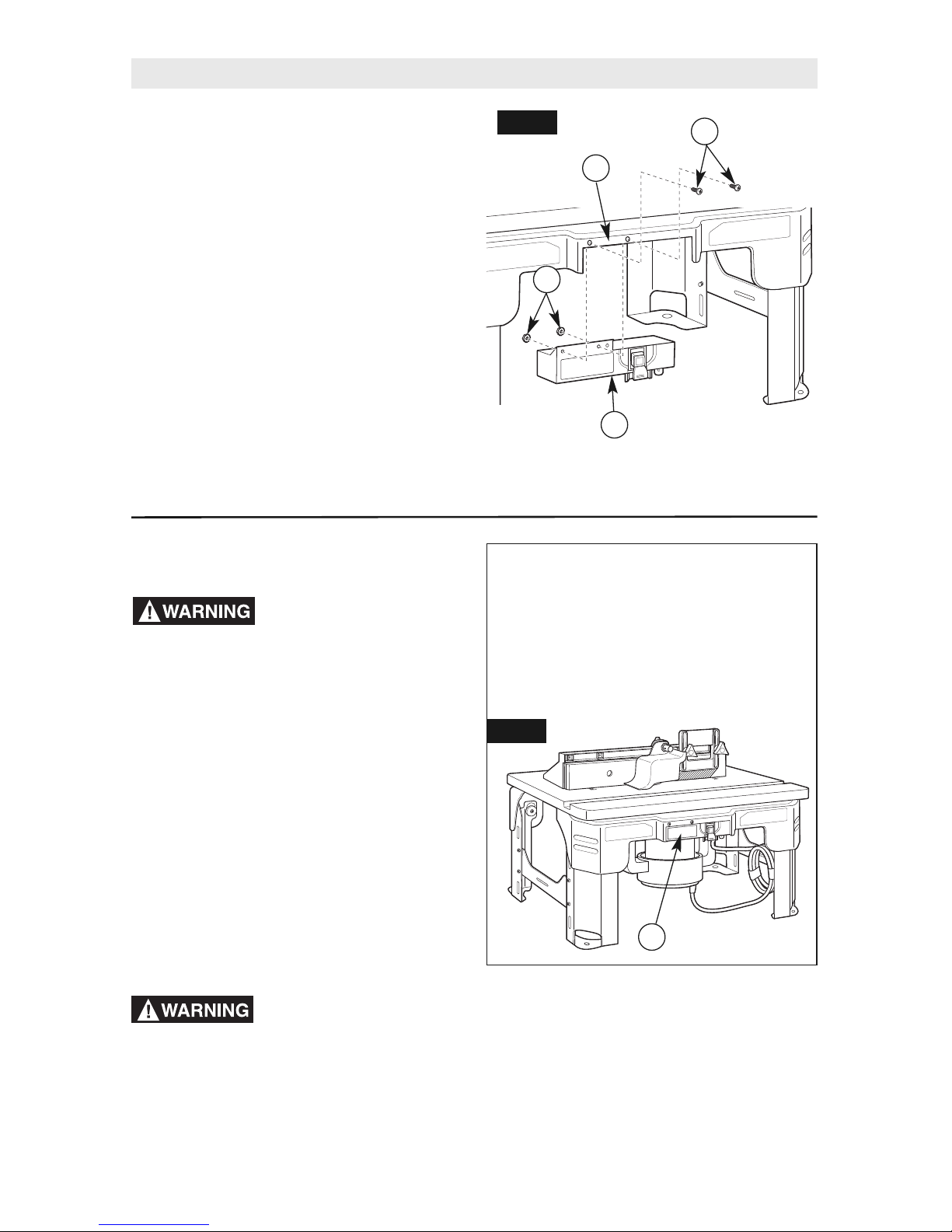
CONNECTING THE ROUTER POWER
CORD TO THE SWITCH (Fig. 17)
Before connecting router
to router table switch
box, ensure that the router switch is OFF,
and that the router table switch box is
unplugged. Such precautionary safety
measures reduce the risk of unintentional tool
operation.
1. Plug the router power cord into one of the
electrical outlets on the back of the switch
box (12).
2. Form the excess power cord into a coil.
3. Wrap two pieces of electrical tape or cable
ties around the coiled cord at opposite
sides of the coil.
4. Allow some slack so that the cord does not
become stretched when it is plugged into
the switch box outlets.
5. If desired at this time, plug the power cord
from an accessory, such as a wet/dry
vacuum or light, into the other outlet.
Before starting to work
ensure that the power
cords from the router, accessories, the
switch case, and the extension cord do not
and cannot come in contact with the router
or any moving parts of the router. Such
precautionary safety measures reduce the
risk of injury due to loss of control.
Cord Positioning
Position the switch cord and any accessory
power cords down the inside of the legs,
then out the rear base of the router table to
an electrical outlet. Secure cord(s) to leg(s)
with electrical tape or tie straps. This will
prevent cord(s) from coming in contact with
any moving parts.
FIG. 17
12
INSTALLING THE SWITCH BOX
(Fig. 16)
If the switch box assembly (12) does not come
preinstalled to the front table housing (6), use the
following instructions to attach the switch box.
1. Place two #10-32 x 5/8" truss-head screws
(30) in the holes in the front table housing
opening.
NOTE: The screw heads should face the
front of the table.
2. While holding the screws in place, slide on
the switch box (12) and start the KEPS nuts
(24) on the screws.
NOTE: The switch box should be behind
the housing opening, and the washer side
of the nuts should be against the switch
box.
3. Hold the KEPS nuts (24) while tightening
the two #10-32 x 5/8" screws (30) to secure
the switch box (12).
FIG. 16
30
12
24
6
Page 18
18
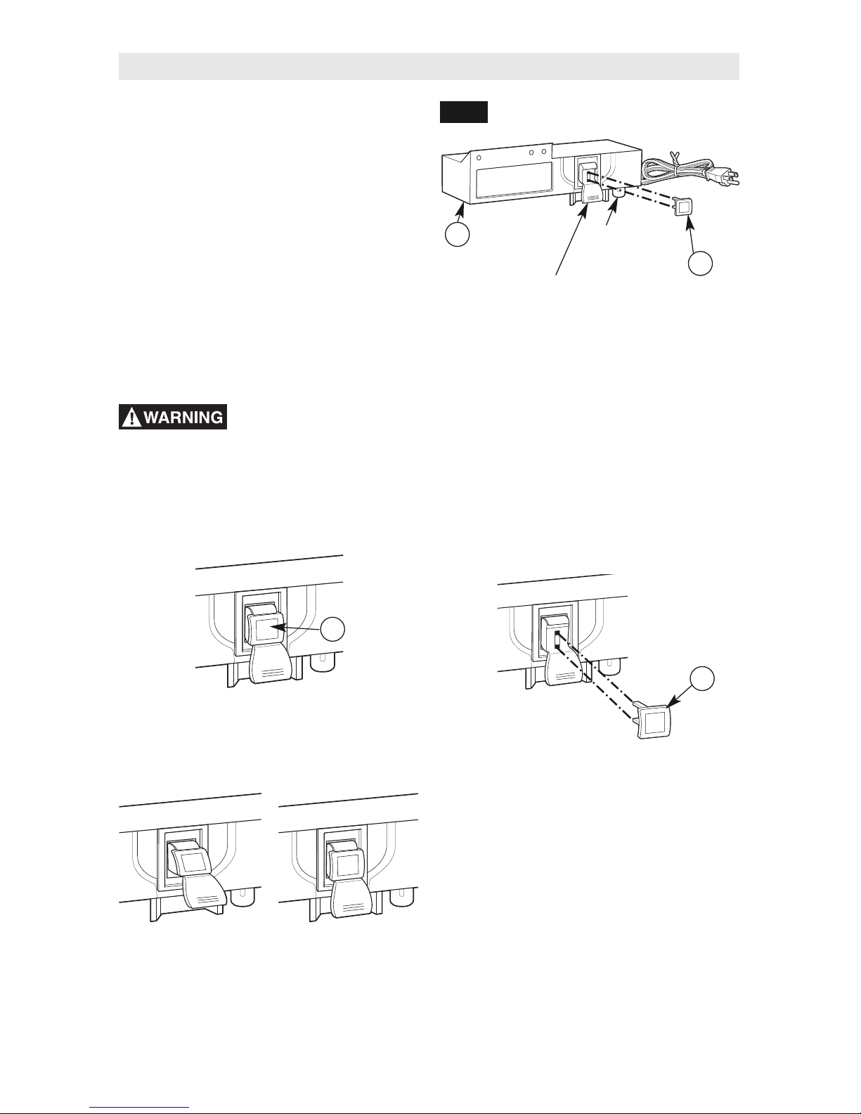
SWITCH OPERATION (Fig. 18)
This section explains the operation and features
of the switch box assembly (B) prior to plugging
the power cord into a power outlet. The intent is
to familiarize the user with the switch operation
without actually turning ON the router.
The switch box (12) (Fig. 18) incorporates a
lockout key (13) to help prevent unauthorized
use by others.
•
The lockout key (13) is the yellow part in
the top of the red plastic paddle. The yellow
lockout key must be completely inserted into
the top of the red plastic paddle and switch
box (12) before the paddle can be turned ON.
•
The circuit reset button for the switch box (12)
is on the bottom right side of the box.
Yellow
lockout key
Switch box
assembly
Red
plastic paddle
(ON/OFF switch)
FIG. 18
Make sure that the
extension cord is not
plugged into an electrical outlet before
proceeding any further.
Router Table Operation
4. To prevent unauthorized use, the switch
can be disabled by removing the yellow
lockout key (13) completely from the top of
the red plastic paddle.
1. Make sure the yellow lockout key (13) is
completely inserted in the top of the red
plastic paddle.
2. To turn the router ON, lift the red plastic
paddle up to the ON position.
3. To turn the router OFF, press the red plastic
paddle to the OFF position.
Circuit
reset button
12
13
13
13
OFF
(DOWN)
ON
(UP)
Page 19

19
Before proceeding any
further, make sure the
switch on the router is in the OFF position
and the switch lever is in the OFF position.
Never leave the router
unattended while it is
running or before it comes to a complete
stop.
Before starting to work
ensure that the power
cords from the router, accessories, the
switch case, and the extension cord do not
and cannot come in contact with the router
or any moving parts of the router. Such
precautionary safety measures reduce the risk
of injury due to loss of control.
The switch power cord can now be
plugged into the extension cord.
ROUTER AND SWITCH OPERATION
This section explains operation of the switch
with the power cord plugged into the extension
cord.
The router will turn ON when the red
paddle on the switch box is pulled up
to the ON position.
1. Position the ON/OFF switch on the router in
the ON position. On certain routers this will
require the use of the switch trigger and
“LOCK/ON” button. (Consult router ownerʼs
manual.) Make sure the switch on the
switch box is in the OFF position when
doing this.
2. To turn the router ON, pull up the red
paddle to the ON position. See page 18.
3. To turn the router OFF, press the red paddle
to the OFF position. See page 18.
CIRCUIT RESET BUTTON
NOTE: In the event of an overload, the
internal switch circuit breaker will trip the
switch box assembly OFF. This will interrupt
power to the router and any accessory
plugged into the switch itself. If this occurs,
proceed as follows:
1. Push the red plastic paddle to the OFF
position and unplug the switch cord from
the wall outlet or extension cord.
2. Turn router switch to OFF position.
3. Remove the workpiece from the router
table.
4. Correct the cause of the overload situation.
For example, if too many accessories are
plugged into the switch or combined
amperage exceeds the switch rating,
remove the accessory. Other causes
include the removal of too much stock
or use of too high a feed rate.
5. Press the circuit breaker button on the
bottom of the switch box.
6. Plug the switch power cord into the wall
outlet or extension cord.
7. Restart the router as described in
the section ROUTER AND SWITCH
OPERATION on this page.
If the switch case does
not work and you have
tried to RESET the circuit reset button as
described above:
•
Unplug ALL electrical connections.
•
Remove the switch from the router
table and obtain a replacement switch
by calling SKIL customer service at
1-877-SKIL999.
WHEN THE ROUTER TABLE IS
NOT IN USE
1. Make sure the switch is in the OFF position.
2. Remove the lockout key (13). See page 18.
3. Store the lockout key in a safe location
where it is not available to children and
other unauthorized persons.
4. Unplug the switch power cord from the wall
outlet or extension cord.
5. Remove the router bit from the router.
6. Position the router collet assembly below
the top of the router table.
NOTE: If the key should become lost or
damaged, replacement keys are available
by calling SKIL customer service at
1-877-SKIL999.
Router Table Operation
Page 20
20
ATTACHING AND USING A
WET/DRY VACUUM
Before connecting
vacuum to router table
switch box, ensure that the vacuum switch is
OFF, and that the router table switch box is
unplugged. Such precautionary safety
measures reduce the risk of unintentional tool
operation.
Do not exceed a total
combined rating of 15
amps when connecting the router and any
accessories such as a light or wet/dry
vacuum. The switch has a rating of 15 amps.
The fence assembly has a port for connecting
a wet/dry vacuum hose with a 2½" nozzle. To
attach, simply push the nozzle into the port
while holding the fence assembly in place.
The vacuum can be plugged into the router
table switch box. Be sure the cord does not
interfere with router operation.
Operating the router table
without a wet/dry vacuum
can result in an excessive buildup of sawdust
and wood chips under the fence assembly and
guard, reducing the performance of the router
table and fence assembly.
RECOMMENDATION: To maximize
performance, regardless of whether a wet/dry
vacuum is being used, remove the sawdust
and wood chips from under the fence
assembly and guard as needed.
RECOMMENDATION: It is always a good
practice to keep the work area clean. As
necessary. remove any accumulated sawdust
and wood chips from the top of the router
table, as well as from the surrounding work
area and floor.
Never place your fingers
near a spinning bit or
under the guard when the router is
plugged in. Such precautionary safety
measures reduce the risk of personal injury.
INSTALLING THE ROUTER BIT
(CUTTER)
Disconnect the router
from the power supply
before making adjustments or changing
accessories. Such precautionary safety
measures reduce the risk of unintentional tool
operation.
Install the router bit according to the instructions
included with your router. Because of the large
variation of router bits, certain router bits may
not always operate in the desired manner with
this router table.
USING THE ROUTER TABLE
Router Table Operation
To ensure that the most popular bits will perform
satisfactorily, install the bit so that the router
collet engages 3/4" of the router bit shank. If the
shank of the router bit bottoms out in the collet,
back out the router bit approximately 1/16" to
allow for proper tightening.
NEVER INSTALL ROUTER BITS WITH
LESS THAN 3/4" OF SHANK
ENGAGEMENT IN THE COLLET.
Page 21
21
ASSEMBLING THE FEATHERBOARD
NOTE: The top/front side of the featherboard
is marked to indicate proper feed direction.
Fence Featherboard (Fig. 19 and Detail 19)
1. Insert two 1/4-20 x 1¾" carriage bolts (32)
through the back of the fence assembly (C)
and the slotted holes in the featherboard
(19). See Detail 19.
2. Thread clamping knobs (18) onto each
carriage bolt (32) and tighten when
featherboard (19) is at the desired height.
3. The workpiece should move with some
resistance but without requiring a great effort.
Featherboard can be mounted in one of two
locations—right or left side of the fence
assembly.
FIG. 19
DETAIL 19
32
18
19
C
Router Table Operation
ROUTING USING FEATHERBOARD
(Fig. 20)
Featherboard is helpful in controlling the
workpiece while routing and assisting in
keeping the workpiece flat on the tabletop.
The fence featherboard helps keep the
workpiece pressed against the fence and
tabletop.
1. Loosen clamping knobs (18) on featherboard
(19) until featherboard is adjustable.
2. Place the workpiece on the router table (1)
so that it is squarely against the fence
assembly (C).
3. Position the featherboard (19) snugly
against the workpiece and tighten the
clamping knobs (18).
4. The workpiece should move with some
resistance but without requiring a great
effort.
Never let go of the
workpiece when routing
until the cut has been completed and the
workpiece is completely clear of the bit.
Such precautionary safety measures reduce
the risk of personal injury and/or property
damage.
•
Featherboards aid in holding the workpiece
in position when routing on a router table.
•
They are NOT intended to hold the
workpiece in place alone when the
workpiece is in contact with the bit, or
at any other time when the bit is turning.
DIRECTION
OF FEED
FIG. 20
C
1
19
18
Page 22
22
For accuracy in routing
and improved control,
the workpiece should be held against the
router table fence when routing.
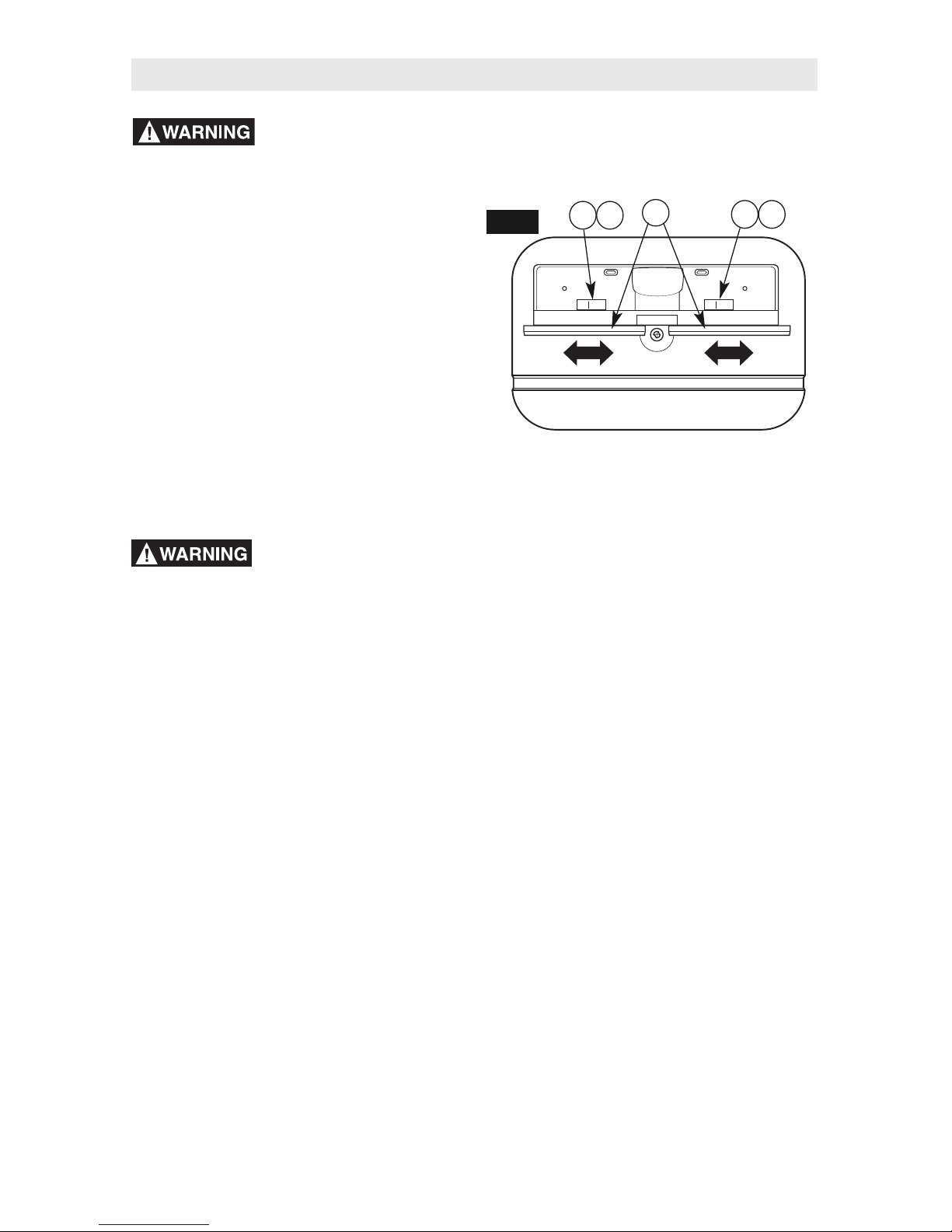
ADJUSTING THE FENCE
FACEPLATES (Fig. 21)
The right and left fence faceplates are
attached to the front face of the router table
fence and can be adjusted inward or outward
from the router bit to allow proper clearance
for different-sized bits. To provide the best
support during routing operations, the fence
faceplates should be as close to the bit as
possible without being able to come in contact
with the bit (typically about 1/4" from the bit is
a suitable distance).
1. Loosen the clamping knob (18) and
carriage bolt (32) securing each fence
faceplate (16) and slide the faceplates
inward or outward from the router bit as
needed.
Always hold the
workpiece against the
router table fence when routing. Such
precautionary safety measures increase
the accuracy in routing and improve the
control of the workpiece reducing the risk
of personal injury.
2. Once the fence faceplates (16) are in
the desired position, tighten the clamping
knobs (18) and carriage bolts (32)
SECURELY.
FIG. 21
18
16
18
Guard not shown for clarity
Router Table Operation
32
32
Page 23
23
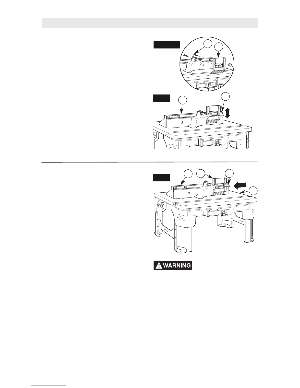
Router Table Operation
ADJUSTING DEPTH AND HEIGHT OF
CUT (Fig. 22 and Detail 22)
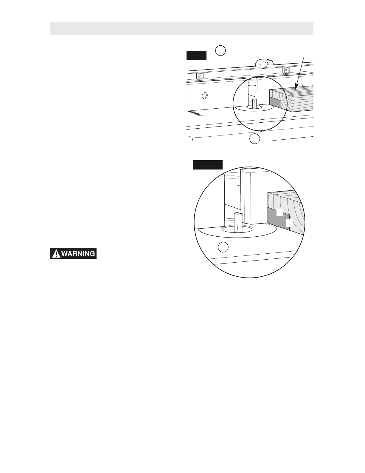
1. Select a board that is smooth and straight,
with good square edges.
2. Mark lines “A” and “B” on the end of the
board, as shown in Detail 22.
•
Line “A” indicates the desired height
of cut.
•
Line “B” indicates the desired final depth
of cut.
•
The area outlined by “A,” “B,” and the edge
of the board is the area that will be cut away.
3. If the desired depth of cut can be cut in a
single pass, loosen the fence clamping
knobs and move the fence forward or
backward until the outermost cutting edge of
the router bit is aligned with line “B.”
NOTE: For deeper cuts, DO NOT attempt to
make the cut in a single pass. Make multiple
shallower cuts, progressively moving the
fence backward until the desired depth of cut
is reached.
4. Use the scales on the tabletop (1) as a guide
to align the fence; then SECURELY tighten
both fence clamping knobs (18).
Always make sure that the
fence and guard cannot
come in contact with the router bit. Failure to
do so will result in damage to the router table
and can cause personal injury.
5. Following the instructions that came with
your router, adjust the router height of cut
until the top of the router bit lines up with line
“A.”
6. Once all adjustments have been made,
double-check that:
•
The router is SECURELY tightened in
the router base.
•
The router bit is SECURELY tightened in
the router collet, with at least 3/4" shank
engagement.
•
The router base is SECURELY tightened to
the bottom of the router table.
AREA OF
DETAIL 22
SCRAP WOOD
A
B
FIG. 22
DETAIL 22
1
18
Behind fence
on base
1
Guard not shown for clarity
7. Remove the board from the table.
NOTE: When making adjustments, use
a piece of scrap wood to make trial cuts
before making the cut with the actual
workpiece.
8. Turn the router on and make desired cut in
the workpiece.
Page 24
24
FULL EDGE CUTTING OR JOINTING
(Figs. 23–25)
For maximum strength and accuracy, boards
that are to be joined together should be
smooth and true. The edges should be true to
the workpiece surface. You can true the edges
using the router table with a straight bit.
NOTE: Use the outfeed shim plate to provide
continuous support for the workpiece as it is
fed past the router bit.
Disconnect the router
from the power supply
before making adjustments or changing
accessories. Such precautionary safety
measures reduce the risk of unintentional
tool operation.
If you are using a wet/dry vac, it should be
connected to the vacuum port on the back of
the fence assembly.
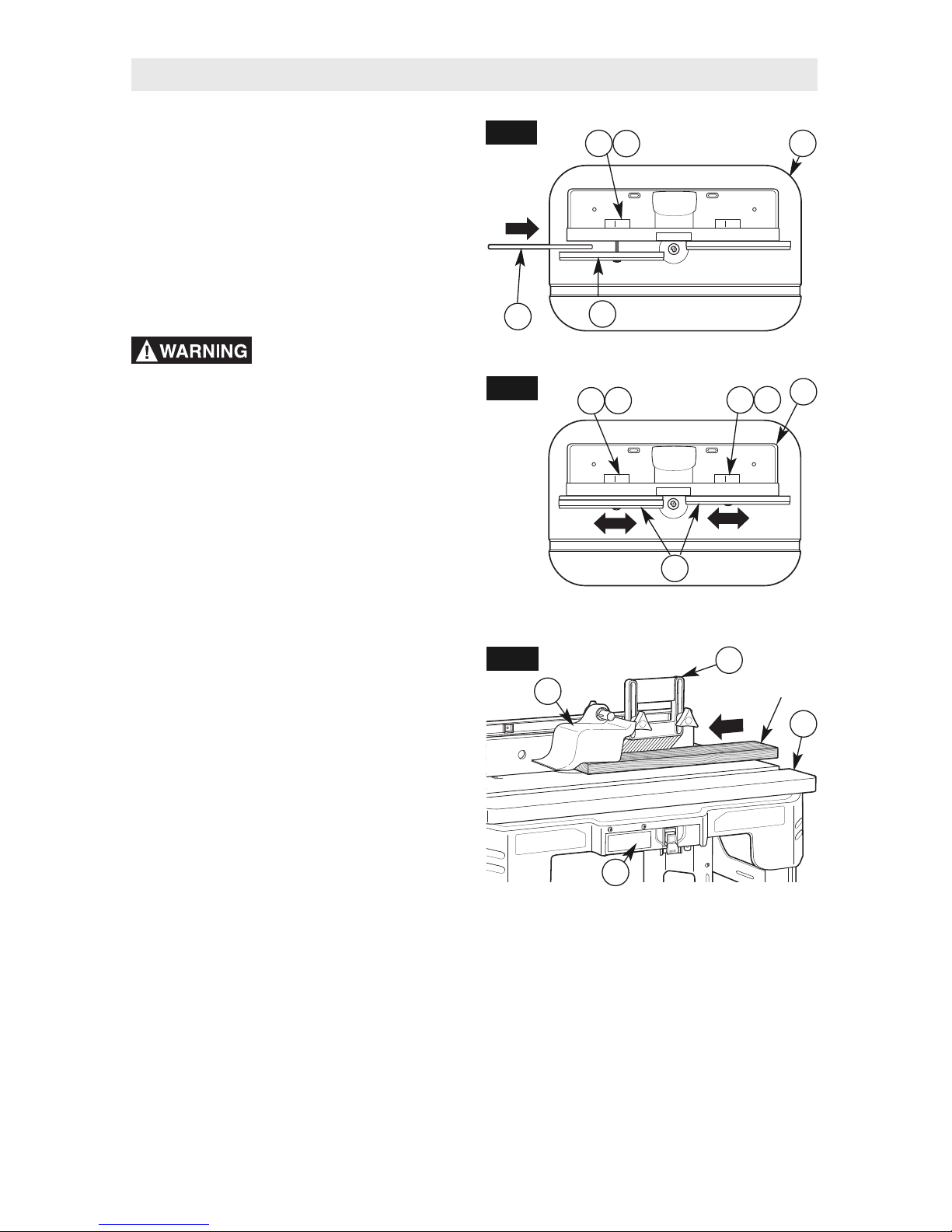
1. Loosen the clamping knob (18) and
carriage bolt (32) securing the outfeed
fence faceplate (16).
2. Align the slot in the outfeed shim plate (17)
with the holes in the outfeed fence faceplate
(16), and slide the outfeed shim plate (17)
between the fence assembly (C) and the
outfeed faceplate (16) (Fig. 23).
Use the outfeed shim plate for a 1/16" offset.
3. Install a straight bit in the router.
4. Position both fence faceplates so that
they clear the bit by 1/4" (Fig. 24).
5. Tighten both clamping knobs (18) and
carriage bolts (32) while holding both
faceplates (16) in place.
6. Place a straight edge or a straight piece
of wood on the table (1) so that it rests
against the outfeed fence faceplate (16).
7. Move the fence back until the straight edge
lines up with the cutting edge of the bit and is
still in contact with the outfeed faceplate (16).
8. Tighten the clamping knobs (18) and
carriage bolts (32).
9. Remove the straight edge or board.
13. Make sure that both the router and switch
box are OFF; then plug the router into the
switch box (12).
14. While firmly holding a piece of scrap wood
against the fence and down against the
router table, feed a piece of scrap wood
toward the bit in the direction shown by
the arrow in Fig. 25.
15. Using the switch box (12), turn the router
OFF. If any adjustments are needed,
unplug the power cord and repeat steps
6–11 until all adjustments are correct.
Once you are satisfied with all settings,
make the cut with the actual workpiece.
WORKPIECE
FIG. 23
FIG. 25
FIG. 24
18
16
C
16
18
C
19
15
1
12
17
18
Guard not shown for clarity
Guard not shown for clarity
10. Adjust the height of the bit so that it will cut
the complete thickness of the workpiece.
11. Position the featherboard (19), if desired.
See ROUTING USING FEATHERBOARD
on page 21.
12. Remove the board from the table (1) and
make sure the overhead guard (15) is
securely in place.
NOTE: When making adjustments, use a
piece of scrap wood to make trial cuts before
making the cut with the actual workpiece.
Router Table Operation
32
32
32
Page 25
25
Router Table Operation
EDGE CUTTING WITH NONPILOTED
ROUTER BITS (Figs. 26 and 27)
Disconnect the router
from the power supply
before making adjustments or changing
accessories. Such precautionary safety
measures reduce the risk of unintentional
tool operation.
NOTE: If the outfeed shim plate is installed,
remove it before proceeding.
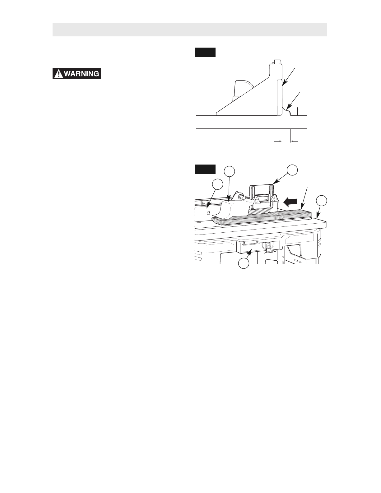
When using nonpiloted router bits, the fence
is used to set the depth of cut. For deep cuts,
do not try to cut the total depth all in one pass.
Repeat the cut, taking multiple smaller cuts.
If you are using a wet/dry vac, it should be
connected to the vacuum port on the back of
the fence assembly.
1. Install the desired bit in the router.
2. Follow the instructions on page 23 to set
the desired depth of cut and height of cut
(Fig. 26). Make sure that the fence and
router are SECURELY in place.
3. Position both fence faceplates (16) so that
they clear the bit by 1/4".
4. Tighten the two clamping knobs and
carriage bolts holding the faceplates (16)
in place.
5. Position the featherboard (19), if desired.
See ROUTING USING FEATHERBOARD
on page 21.
6. Remove the board from the table (1) and
make sure the overhead guard (15) is
securely in place.
NOTE: When making adjustments, use
a piece of scrap wood to make trial cuts
before making the cut with the actual
workpiece.
7. Make sure that both the router and switch
box are OFF; then plug the router into
the switch box (12).
WORKPIECE
FENCE
FACING
ROUTER BIT
DEPTH OF CUT
HEIGHT
OF CUT
Guard not shown for clarity
FIG. 26
FIG. 27
16
15
19
12
1
8. While firmly holding a piece of scrap wood
against the fence and down against the
router table (1), feed a piece of scrap wood
toward the bit in the direction shown by the
arrow in Fig. 27.
9. Using the switch box (12), turn the router
OFF. If any adjustments are needed, unplug
the power cord and repeat steps 2–8 until
all adjustments are correct. Once you are
satisfied with all settings, make the cut with
the actual workpiece.
Page 26
26
EDGE CUTTING WITH PILOTED
ROUTER BITS (Figs. 28 and 29)
Disconnect the router
from the power supply
before making adjustments or changing
accessories. Such precautionary safety
measures reduce the risk of unintentional
tool operation.
NOTE: If the outfeed shim plate is installed,
remove it before proceeding.
If you are using a wet/dry vac, it should be
connected to the vacuum port on the back of
the fence assembly.
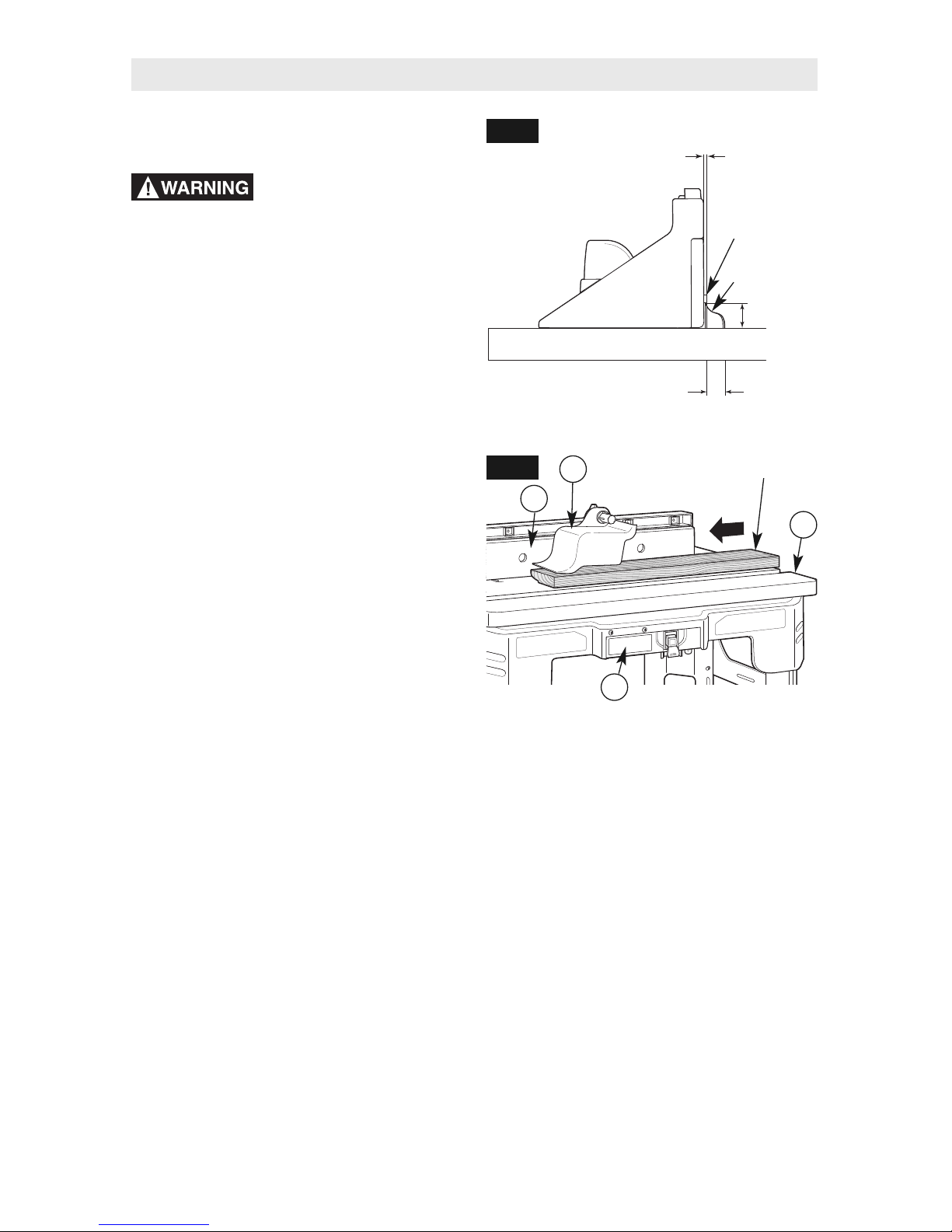
1. Install the desired piloted bit in the router.
2. Follow the instructions on page 23 to set
the desired height of cut (Fig. 28). Make
sure that the router is securely in place.
3. Adjust the router table fence back just
enough that the pilot on the router bit will
control the depth of cut. The router bit pilot
should just barely protrude past the fence
faceplates (16). Tighten the fence clamping
knobs SECURELY.
4. Position both fence faceplates (16) so that
they clear the bit by 1/4".
5. Tighten the two clamping knobs and
carriage bolts holding the fence faceplates
(16) in place.
6. Remove the board from the table (1) and
make sure the overhead guard (15) is
securely in place.
NOTE: When making adjustments, use
a piece of scrap wood to make trial cuts
before making the cut with the actual
workpiece.
7. Make sure that both the router and switch
box are OFF; then plug the router into the
switch box (12).
PILOTED
ROUTER BIT
DEPTH OF CUT
HEIGHT
OF CUT
ROUTER BIT
PILOT
CLEARANCE
BETWEEN
FENCE AND
BIT
WORKPIECE
Guard not shown for clarity
FIG. 28
FIG. 29
16
15
12
1
Router Table Operation
8. While firmly holding a piece of scrap wood
against the fence faceplate (16) and down
against the router table (1), feed a piece of
scrap wood toward the bit in the direction
shown by the arrow in Fig. 29.
9. Using the switch box (12), turn the router
OFF. If any adjustments are needed, unplug
the power cord and repeat steps 2–8 until
all adjustments are correct. Once you are
satisfied with all settings, make the cut with
the actual workpiece.
Page 27

27
GROOVING, FLUTING, AND
VEINING (Figs. 30 and 31)
Disconnect the router
from the power supply
before making adjustments or changing
accessories. Such precautionary safety
measures reduce the risk of unintentional
tool operation.
NOTE: If the outfeed shim plate is installed,
remove it before proceeding.
When performing these routing operations,
it is recommended to use the featherboard.
For best results and maximum accuracy, the
side of the workpiece that will be against the
fence must be square and straight.
If you are using a wet/dry vac, it should be
connected to the vacuum port on the back of
the fence assembly.
1. Install the desired end-cutting bit in the router.
2. Follow the instructions on page 23 to set
the desired depth of cut (location of cut)
and height of cut (Fig. 30). Make sure that
the fence and router are securely in place.
IMPORTANT: For deep cuts, do not try to cut
the total depth (controlled by the router bit
height) all in one pass. Repeat the cut, taking
smaller cuts until the desired depth is reached.
3. Position both fence faceplates (16) so that they
provide continuous support of the workpiece.
4. Tighten the two clamping knobs and
carriage bolts holding the fence faceplates
(16) in place.
5. Position the featherboard (19), if desired.
See ROUTING USING FEATHERBOARD
on page 21.
6. Remove the board from the table (1) and
make sure the overhead guard (15) is
securely in place.
NOTE: When making adjustments, use a
piece of scrap wood to make trial cuts before
making the cut with the actual workpiece.
FENCE
FACING
END CUTTING
ROUTER BIT
LOCATION OF CUT
HEIGHT
OF CUT
Guard not shown for clarity
WORKPIECE
FIG. 30
FIG. 31
16
15
19
12
1
Router Table Operation
7. Make sure that both the router and switch
box (12) are OFF; then plug the router into
the switch box (12).
8. While firmly holding a piece of scrap wood
against the fence faceplate (16) and down
against the router table (1), feed a piece of
scrap wood toward the bit in the direction
shown by the arrow in Fig. 31.
9. Using the switch box (12), turn the router
OFF. If any adjustments are needed, unplug
the power cord and repeat steps 2–8 until
all adjustments are correct. Once you are
satisfied with all settings, make the cut with
the actual workpiece.
Page 28

28
Router Table Operation
USING A MITER GAUGE (Fig. 32)
The miter gauge slot will accommodate most
stationary table saw miter gauges that
measure 3/4" wide x 3/8" deep.
NOTE: For ALL routing operations requiring
the use of the miter gauge with the fence, BE
SURE to align the fence using the scales on
the top of the router table before making any
cuts. Miters can be cut by loosening the knob
on the protractor head, turning the protractor
head up to 60° in either direction, and
retightening the protractor head knob.
Make a test pass with a scrap piece of wood
before making a cut to be sure the fence is
properly aligned. Adjust as required and fasten
the fence securely before making the cut.
MITER
GAUGE
FIG. 32
Guard not shown for clarity
Page 29

29
Table des Matiéres
CONSIGNES DE SÉCURITÉ
IMPORTANTS . . . . . . . . . . . . . . . . . .29–34
Liste des pièces. . . . . . . . . . . . . . . . 35–37
Assemblage de la table à toupie
. . . 38–43
Fonctionnement de la table
à toupie. . . . . . . . . . . . . . . . . . . . . . . 44–56
Consignes de sécurité générales concernant
les outils électriques
Aire de travail
Veillez à ce que lʼaire de travail soit propre et
bien éclairée. Le désordre et le manque de
lumière favorisent les accidents.
Nʼutilisez pas dʼoutils électriques dans une
atmosphère explosive, par exemple en
présence de liquides, de gaz ou de
poussières inflammables. Les outils électriques
créent des étincelles qui pourraient enflammer
les poussières ou les vapeurs.
Tenez à distance les curieux, les enfants et les
visiteurs pendant que vous travaillez avec un
outil électrique. Ils pourraient vous distraire et
vous faire faire une fausse manoeuvre.
Sécurité électrique
Les outils avec mise à la terre doivent être
branchés sur une prise installée correctement
et reliée à la terre conformément à toutes les
normes et décrets. Nʼenlevez jamais la fiche
de terre et ne modifiez jamais la prise.
Nʼutilisez jamais dʼadaptateur de prise. Si
vous nʼêtes pas sûr que votre prise est
correctement reliée à la terre, consultez un
électricien. Si lʼoutil présente une avarie
électrique ou tombe en panne, le circuit de terre
sert de chemin à faible résistance pour conduire
le courant et lʼempêcher de passer à travers
lʼutilisateur. Un outil incorrectement relié à la terre
risque de causer un choc électrique, des brûlures
ou une électrocution. Les outils avec mise à la
terre sont munis dʼun cordon à trois fils et dʼune
prise à trois fiches. Avant de brancher lʼoutil,
assurez-vous que la tension de la prise
correspond, à celle indiquée sur la plaque
signalétique. Nʼutilisez pas dʼoutils prévus pour
courant alternatif seulement avec une source
de courant continu.
Les outils à double isolation sont équipés
dʼune fiche polarisée (une des lames est plus
large que lʼautre), qui ne peut se brancher que
dʼune seule façon dans une prise polarisée. Si
la fiche nʼentre pas parfaitement dans la prise,
inversez sa position; si elle nʼentre toujours
pas bien, demandez à un électricien qualifié
dʼinstaller une prise de courant polarisée. Ne
modifiez pas la fiche de lʼoutil. La double
isolation élimine le besoin dʼun cordon
dʼalimentation à trois fils avec mise à la terre
ainsi que dʼune prise de courant mise à la terre.
Avant de brancher lʼoutil, assurez-vous que la
tension de la prise correspond, à celle indiquée
sur la plaque signalétique. Nʼutilisez pas dʼoutils
prévus pour courant alternatif seulement avec
une source de courant continu.
Évitez tout contact corporel avec des surfaces
mises à la terre (tuyauterie, radiateurs,
cuisinières, réfrigérateurs, etc.). Le risque de
secousse électrique est plus grand si votre corps
est en contact avec la terre. Si lʼutilisation de lʼoutil
électrique dans un endroit humide est inévitable, un
disjoncteur de fuite à la terre doit être utilisé pour
alimenter votre outil. Des chaussures et des gants
en caoutchouc dʼélectricien contribueront à
accroître davantage votre sécurité personnelle.
Nʼexposez pas les outils électriques à la
pluie ou à lʼeau. La présence dʼeau dans un
outil électrique augmente le risque de secousse
électrique.
Ne maltraitez pas le cordon. Ne transportez
pas lʼoutil par son cordon et ne débranchez
pas la fiche en tirant sur le cordon. Nʼexposez
pas le cordon à la chaleur, à des huiles, à des
arêtes vives ou à des pièces en mouvement.
Remplacez immédiatement un cordon
endommagé. Un cordon endommagé augmente
le risque de secousse électrique.
Lorsque vous utilisez un outil électrique à
lʼextérieur, employez une rallonge pour
lʼextérieur marqué « W-A » ou « W ». Ces
cordons sont faits pour être utilisés à lʼextérieur
et réduisent le risque de secousse électrique.
Reportez-vous aux « Information important au
sujet des cordons de rallonge ».
Vous devez lire et comprendre toutes les instructions. Le non-respect,
même partiel, des instructions ci-après entraîne un risque de blessures graves.
CONSERVEZ CES INSTRUCTIONS
Page 30

30
Sécurité des personnes
R
estez alerte, concentrez-vous sur votre
t
ravail et faites preuve de jugement. Nʼutilisez
p
as un outil électrique si vous êtes fatigué ou
s
ous lʼinfluence de drogues, dʼalcool ou de
m
édicaments. Un instant dʼinattention suffit pour
e
ntraîner des blessures graves.
L
aissez les gardes en place. Gardez-les en
p
lace, en bon état et bien réglés.
Méfiez-vous dʼun mise en marche accidentel.
A
vant de brancher lʼoutil, assurez-vous que son
i
nterrupteur est sur ARRÊT. Le fait de transporter
un outil avec le doigt sur la détente ou de brancher
un outil dont lʼinterrupteur est en position MARCHE
peut mener tout droit à un accident.
Enlevez les clés de réglage ou de serrage
avant de mettre en marche lʼoutil. Une clé
laissée dans une pièce tournante de lʼoutil peut
provoquer des blessures.
Ne vous penchez pas trop en avant. Maintenez un bon appui et restez en équilibre
entout temps. Un bonne stabilité vous permet de
mieux réagir à une situation inattendue.
Portez toujours des lunettes de sécurité
(protection de la tête). Portez des lunettes de
sécurité (conformes à la norme ANSI Z87.1). Portez
des souliers de travail non dérapants et un casque,
si nécessaire. Portez également un masque facial
ou à poussière si lʼopération de coupe soulève de
la poussière, et des protecteurs dʼoreille (bouchons
ou casque) si vous utilisez votre instrument
longtemps.
Utilisation et entretien des outils
Immobilisez le matériau sur une surface
stable au moyen de brides ou de toute autre
façon adéquate. Le fait de tenir la pièce avec la
main ou contre votre corps offre une stabilité
insuffisante et peut amener un dérapage de
lʼoutil.
Ne forcez pas lʼoutil. Utilisez lʼoutil approprié
à la tâche. Lʼoutil correct fonctionne mieux et de
façon plus sécuritaire. Respectez aussi la vitesse
de travail qui lui est propre.
Nʼutilisez pas un outil si son interrupteur est
bloqué. Un outil que vous ne pouvez pas
commander par son interrupteur est dangereux
et doit être réparé.
D
ébranchez la fiche de lʼoutil avant dʼeffectuer
un réglage, de changer dʼaccessoire ou de
ranger lʼoutil. De telles mesures préventives de
sécurité réduisent le risque de mise en marche
accidentel de lʼoutil.
Laissez les gardes en place. Gardez-les en
place, en bon état et bien réglés.
R
angez les outils hors de la portée des enf
ants et dʼautres personnes inexpérimentées.
Les outils sont dangereux dans les mains
dʼutilisateurs novices.
Ne laissez pas fonctionner lʼoutil sans
s
urveillance. Assurez-vous que lʼoutil est
complètement arrêté AVANT DE VOUS
ÉLOIGNER.
Prenez soin de bien entretenir les outils. Les
outils de coupe doivent être toujours bien
affûtés et propres. Des outils bien entretenus,
dont les arêtes sont bien tranchantes, sont moins
susceptibles de coincer et plus faciles à diriger.
Toute altération ou modification constitue un
usage erroné et peut causer un danger.
Soyez attentif à tout désalignement ou
coincement des pièces en mouvement, à tout
bris ou à toute autre condition préjudiciable
au bon fonctionnement de lʼoutil. Si vous
constatez quʼun outil est endommagé,
faites-le réparer avant de vous en servir. De
nombreux accidents sont causés par des outils
en mauvais état. Élaborez un calendrier
dʼentretien périodique de votre outil.
Nʼutilisez que des accessoires que le
fabricant recommande pour votre modèle
dʼoutil. Certains accessoires peuvent convenir à
un outil, mais être dangereux avec un autre.
Réparation
La réparation des outils électriques doit être
confiée à un réparateur qualifié. Lʼentretien ou
la réparation dʼun outil électrique par un amateur
peut avoir des conséquences graves. Ainsi, des
fils internes peuvent être mal placés ou pincés,
des ressorts de rappel de garde peuvent être
montés erronément.
Pour la réparation dʼun outil, nʼemployez que
des pièces de rechange dʼorigine. Lʼemploi
de pièces non autorisées ou le non-respect des
instructions dʼentretien peut créer un risque de
secousse électrique ou de blessures. Certains
agents nettoyants tels quʼessence, tétrachlorure
de carbone, ammoniac, etc., peuvent abîmer les
pièces en plastique.
Consignes de sécurité supplémentaires
pour les tables à toupie
Ne soulevez la table à toupie que par ses
bords. Si vous soulevez la table par toute autre
surface, il pourrait en résulter des blessures
corporelles.
Veuillez toujours faire tourner lʼassemblage
des pieds par leur extrémité. Gardez vos
doigts à lʼécart des charnières. Ceci vous
permet dʼéviter les points de pincement.
Ne faites jamais tourner lʼassemblage des
pieds avant quʼils ne soient en position
déverrouillée. Ceci évitera tout dommage aux
pieds ou aux boîtiers de la table. Votre table peut
sʼeffondrer si les pieds ou les boîtiers de la table
sont cassés.
Nʼutilisez pas la table à toupie avant que
toutes les étapes de montage et dʼinstallation
nʼaient été effectuées. Avant chaque
utilisation, vérifiez que les attaches et les
pinces de maintien de la toupie soient bien
serrées. Une table ou une toupie desserrée est
instable et peut se déplacer pendant lʼutilisation,
ce qui peut provoquer des dommages à la
propriété ou des blessures corporelles graves.
Page 31

31
Consignes de sécurité supplémentaires
pour les tables à toupie
Avant dʼutiliser une toupie sur une table à
toupie, assurez-vous que les pieds de la table
sont complètement dépliés et verrouillés et
q
ue lʼensemble (table à toupie et toupie) est
p
lacé sur une surface pleine, plane et de
n
iveau qui ne risque pas de se renverser. De
telles mesures de sécurité préventives réduisent
le risque dʼun déplacement inattendu de la table
pendant son utilisation, ce qui peut provoquer des
dommages à la propriété ou des blessures
corporelles graves.
Débranchez la toupie de lʼalimentation
électrique avant dʼinstaller cette toupie sur la
table, dʼeffectuer des réglages, de changer
dʼaccessoires, de retirer la toupie de la table,
dʼeffectuer la maintenance ou encore lors du
rangement de lʼoutil. De telles mesures de
sécurité préventives réduisent le risque dʼune
mise en marche involontaire de lʼoutil.
Ne branchez pas le cordon dʼalimentation du
moteur de la toupie dans une prise murale
standard. Le cordon dʼalimentation de la
toupie doit toujours être branché à la boîte
de commutation de la table à toupie. Les
interrupteurs et commandes des outils électriques
doivent être à votre portée en cas dʼurgence.
Vos doigts ne doivent pas toucher les bornes
de la fiche lorsque vous branchez ou
débranchez celle-ci de la prise.
Avant de connecter votre toupie ou votre
aspirateur à la boîte de commutation de la
table à toupie, assurez-vous que lʼaspirateur
est éteint et que la boîte de commutation de la
table à toupie est débranchée. De telles
mesures de sécurité préventives réduisent le
risque dʼune mise en marche involontaire de
lʼoutil.
Avant dʼutiliser votre table à toupie, vérifiez
que la toupie est correctement fixée à la base
de la table à toupie. Lorsque vous travaillez,
vérifiez périodiquement le serrage de la
fixation de la base de la toupie. Les fixations
du moteur peuvent se desserrer à cause des
vibrations causées par les opérations de coupe et
le moteur de la toupie peut se détacher de la table
à toupie.
Avant de commencer à travailler, assurez-vous
que les cordons dʼalimentation des
accessoires de toupie et de la boîte de
commutation ainsi que la rallonge ne sont pas
et ne peuvent pas entrer en contact avec la
toupie ou toute pièce rotative de la toupie. De
telles mesures de sécurité préventives réduisent
le risque de blessure par perte de contrôle.
Nʼutilisez pas la table à toupie sans le garde
supérieur sauf si le retrait du garde est requis
pour une opération de coupe particulière.
Remettez le garde en place immédiatement
après avoir terminé lʼopération de coupe.
Retirez toute poussière, copeau de bois et
a
utre particule étrangère qui peut affecter son
e
fficacité. Le garde permet dʼéviter le contact
a
ccidentel des mains avec la fraise en rotation.
N
ʼutilisez pas de fraise ayant un diamètre de
c
oupe supérieur au trou de dégagement de la
plaque amovible ou de la bague amovible du
plateau de la table. La fraise pourrait toucher la
plaque ou la bague amovible et projeter des
fragments.
Nʼutilisez jamais de fraise émoussée ou
endommagée. Les fraises endommagées
peuvent se casser pendant lʼutilisation. Les fraises
émoussées nécessitent davantage de force pour
pousser la pièce à travailler, ce qui peut causer la
rupture de la fraise ou le rebond du matériau.
Manipulez les fraises acérées avec précaution.
De telles mesures de sécurité préventives
réduisent le risque de blessure.
Ne modifiez pas le trou de fraise de la plaque
ou de la bague amovible. Faites correspondre
le diamètre de coupe de la fraise avec le
diamètre interne de la bague ou plaque
amovible de façon à ce que la différence soit
inférieure à 1/16 po sur un côté. Les bagues
amovibles sont utilisées pour réduire lʼespace
entre le diamètre de coupe dʼune fraise et la table
pour que les pièces à travailler reposent
entièrement sur la table lors du toupillage.
Installez la fraise conformément aux
instructions données dans le manuel
dʼutilisation de la toupie. Attachez fermement
la fraise dans le mandrin à pince avant de
couper. Le fait de fixer correctement la fraise
avant toute coupe réduit le risque que la fraise ne
se desserre pendant son utilisation.
Ne placez jamais vos doigts près dʼune fraise
en rotation ou sous le garde lorsque la toupie
est branchée. De telles mesures de sécurité
préventives réduisent le risque de blessure.
Ne tenez jamais la pièce à travailler du côté
sortie de la fraise. Le fait de pousser la pièce
contre le côté sortie du guide peut provoquer le
bourrage du matériau et un rebond potentiel qui
pourrait entraîner votre main vers la fraise.
Utilisez le guide pour guider la pièce à
travailler et pour garder le contrôle de cette
même pièce. Ne placez pas la pièce entre la
fraise et le guide lorsque vous toupillez le bord
de la pièce. Ce positionnement peut provoquer
un coincement du matériau et un risque de
rebond.
Les toupies sont conçues pour travailler le
bois, les matières semblables au bois, le
plastique ou les matières laminées. Nʼutilisez
pas la toupie et la table à toupie pour
découper ou façonner des pièces métalliques.
Assurez-vous que la pièce ne contient pas de
clou ou autre objet dur. Le découpage de clou
peut entraîner la perte de contrôle de lʼoutil ou de
la pièce.
Page 32

32
Consignes de sécurité supplémentaires
pour les tables à toupie
Ne démarrez jamais lʼoutil lorsque la fraise est
engagée dans le matériau. Le bord tranchant de
la fraise peut accrocher le matériau et entraîner
l
a perte de contrôle de la pièce à travailler.
Avancez la pièce à travailler seulement
dans le sens opposé à la rotation de la
fraise. Ne faites pas revenir la pièce vers la
fraise. Vu depuis le dessus de la table, la
fraise tourne dans le sens inverse des
aiguil-les dʼune montre. Si la pièce revient
vers la fraise, elle peut « monter » sur la
fraise, ce qui entraînera la pièce à travailler et
potentiel-lement votre main vers la fraise en
rotation.
Ne faites pas avancer votre pièce à
travailler vers la fraise si la majorité de la
pièce se trouve entre le guide et la fraise.
Ceci crée un coincement contre le guide qui
provoque une situation dangereuse avec la
fraise exposée. La pièce peut alors être
poussée de la table et peut entraîner une
perte de contrôle pendant la coupe.
Ne coupez pas les matériaux déformés,
branlants ou autrement instables. La table
à toupie est conçue pour découper des
pièces planes, droites et perpendiculaires.
Si le matériau est stable mais légèrement
courbé, coupez-le avec le côté concave
placé contre la table ou le guide. Le fait de
couper le matériau avec le côté concave vers
le haut ou en direction opposée à la surface
dʼappui peut provoquer une perte de contrôle
suite au roulement et au rebond du matériau
déformé ou instable.
Utilisez des supports auxiliaires dʼentrée et de
sortie pour les pièces longues ou larges. Les
pièces de grandes dimensions qui ne sont pas
soutenues correctement peuvent tomber de la
table ou faire basculer cette dernière.
Utilisez des poussoirs, des guides biseautés
montés à la verticale et à lʼhorizontale et
autres serre-joints pour maintenir la pièce.
Ces poussoirs, guides biseautés et serre-joints
éviteront que les mains ne se trouvent à
proximité de la fraise pour tenir la pièce.
Ne lâchez jamais la pièce à travailler pendant
le toupillage avant que la coupe ne soit
terminée et que la pièce à travailler ne soit
complètement dégagée de la fraise. De telles
mesures de sécurité préventives réduisent le
risque de blessure et de dommages à la
propriété. Les guides biseautés permettent de
maintenir la pièce à travailler en position lors du
toupillage sur une table à toupie. Ils ne sont pas
conçus pour maintenir, à eux seuls, la pièce à
travailler lorsque cette pièce entre en contact
avec la fraise ou à tout autre moment où la fraise
est en rotation.
V
euillez toujours maintenir la pièce à travailler
c
ontre le guide lorsque vous toupillez. De
t
elles mesures de sécurité préventives
augmentent la précision du toupillage et
améliorent le contrôle de la pièce à travailler,
réduisant ainsi le risque de blessure.
Ne laissez jamais la toupie sans surveillance
si elle est en marche ou si elle nʼest pas
complètement arrêtée. De telles mesures de
sécurité préventives réduisent le risque de
blessure et de dommages à la propriété.
Nʼutilisez pas la table comme établi ou plan
de travail. En utilisant votre table pour tout
autre but que de toupiller, vous risquez de
lʼendommager et de rendre son utilisation
dangereuse.
Ne montez jamais sur la table et ne lʼutilisez
jamais comme une échelle ou un
échafaudage. La table pourrait basculer ou lʼoutil
de coupe pourrait être accidentellement touché.
Lorsque vous effectuez lʼentretien de votre
outil, nʼutilisez que des pièces de rechange
recommandées par SKIL. Veuillez suivre les
instructions dans la section Maintenance de
ce manuel. Lʼutilisation de pièces non autorisées
ou le non-respect des consignes de maintenance
peut provoquer des blessures corporelles.
Les travaux à la machine tel que ponçage,
sciage, meulage, perçage et autres travaux
du bâtiment peuvent créer des poussières
contenant des produits chimiques qui sont
des causes reconnues de cancer, de
malformation congénitale ou dʼautres
problèmes reproductifs. Ces produits
chimiques sont, par exemple :
•
Le plomb provenant des peintures à base de
plomb
•
Les cristaux de silices provenant des briques,
du ciment, et dʼautres produits de maçonnerie
•
Lʼarsenic et le chrome provenant des bois
traités chimiquement
Le niveau de risque dû à cette exposition varie
avec la fréquence de ces types de travaux. Pour
réduire lʼexposition à ces produits chimiques, il
faut travailler dans un lieu bien ventilé et porter
un équipement de sécurité approprié tel que
certains masques à poussière conçus
spécialement pour filtrer les particules
microscopiques.
Page 33

33
Positionnement du guide et sens dʼavance incorrects
N
e faites pas avancer votre
pièce à travailler vers la fraise
si la majorité de la pièce se trouve entre le guide et
l
a fraise. Ceci crée un « coincement du guide » qui est
d
angereux pour deux raisons :
•
Le devant de la fraise est exposé lors de la coupe
(Fig. A).
•
La fraise peut monter où la fraise pénètre dans la pièce
à travailler dans la même direction que la direction
dʼengagement. La pièce peut alors être poussée de la
table et peut entraîner une perte de contrôle pendant la
coupe (Fig. A).
Avancez la pièce à travailler
seulement dans le sens opposé à la rotation de la fraise. Ne faites pas revenir la
pièce à travailler dans la fraise. Vu depuis le dessus de
la table, la fraise tourne dans le sens inverse des aiguilles
dʼune montre. Le retour de la pièce vers la fraise est dangereux pour deux raisons :
•
Elle peut « monter » sur la fraise où la pièce à travailler
est poussée de la surface de la table dans la direction
de la rotation de la fraise, ce qui entraînera la pièce à
travailler et potentiellement vos mains vers la fraise en
rotation (Fig. B).
•
Il est difficile de maintenir la pièce à travailler contre le
guide parce que la rotation de la fraise tendrait à lʼen
éloigner.
FIG. A
FIG. B
Pièce
Fraise exposée
Direction
d’avance
Direction
d’avance
correcte
Pièce
Direction
incorrecte
Coupe en avalant
Une rallonge avec des
conducteurs de
dimensions adéquates pouvant supporter le
courant nécessaire à votre outil doit être
utilisée. Ceci préviendra une baisse excessive
de tension, une perte de courant ou une
surchauffe. Les outils mis à la terre doivent être
utilisés avec des rallonges à 3 brins pourvues de
fiches et de prises à trois broches.
REMARQUE : Plus le calibre est petit, plus le fil est
gros.
CALIBRES DE CORDONS RALLONGES
RECOMMANDÉS OUTILS 120 VOLTS
COURANT ALTERNATIF
Information importante au sujet des cordons rallonges
Intensité
nominale
de l’outil
Longueur en pieds
Longueur en mètres
3-6
6-8
8-10
10-12
12-16
18 16 16 14 0,75 0,75 1,5 2,5
18 16 14 12 0,75 1,0 2,5 4,0
18 16 14 12 0,75 1,0 2,5 4,0
16 16 14 12 1,0 2,5 4,0 —
14 12 — — — — — —
25 50 100 150 15 30 60 120
Calibre A.W.G.
Calibre en mm
2
Page 34

34
I
MPORTANTE : Certains des symboles suivants peuvent être utilisés sur votre outil. Veuillez les
é
tudier et apprendre leur signification. Une interprétation appropriée de ces symboles vous permettra
dʼutiliser lʼoutil de façon plus efficace et sécuritaire.
Symbole Nom Désignation/Explication
V Volts Tension (potentiel)
A Ampères Courant
H
z Hertz Fréquence (cycles par seconde)
W Watt Puissance
kg Kilogrammes Poids
min Minutes Temps
s
Secondes Temps
Ø Diamètre Taille des fraises, des meules, etc.
n
0
Vitesse à vide Vitesse de rotation, à vide
.../min Révolutions ou mouvements Révolutions, courses, vitesse périphérique,
par minute alternatifs par minute orbites, etc.
0 Position dʼarrêt Vitesse zéro, couple zéro …
1, 2, 3, ... Réglages du sélecteur Réglages de vitesse, de couple ou de position.
I, II, III, Un nombre plus élevé correspond à une
vitesse plus élevée
Sélecteur variable à lʼinfini La vitesse augmente depuis le réglage 0
avec arrêt
Flèche Action dans la direction de la flèche
Courant alternatif Type ou caractéristique du courant
Courant continu Type ou caractéristique du courant
Courant alternatif ou continu Type ou caractéristique du courant
Construction classe II Désigne des outils de construction à double
isolation
Borne de terre Borne de mise à la terre
Symbole dʼavertissement Attire lʼattention de lʼutilisateur sur les messages
dʼavertissement
Sceau Ni-Cad RBRC Désigne le programme de recyclage des
piles Ni-Cad
Symboles
0
Ce symbole indique que les composants de cet outil
sont reconnus par le Underwriters Laboratory comme
conformes aux normes canadiennes.
Page 35

35
Liste des pièces
R
eportez-vous à la liste des pièces ci-dessous et aux pages 36 et 37.
•
S
i une (ou plusieurs)
pièce est manquante,
QUELLE QUʼELLE SOIT, nʼessayez pas de
monter, installer ou utiliser votre table à toupie
tant que la pièce manquante nʼa pas été
t
rouvée ou remplacée, et votre table à toupie
c
orrectement assemblée conformément aux
instructions de ce manuel.
•
Pour les pièces manquantes ou lʼassistance
technique, appel 1-877-SKIL999 (1-877754-5999).
•
V
otre table à toupie est livrée démontée afin de
simplifier la manutention et réduire les risques de
dommages lors du transport.
•
P
our vous assurez que toutes les pièces
ont été incluses, séparez chaque pièce du
matériel dʼemballage et comparez-la à son
i
llustration et à sa description dans la liste des
pièces figurant à la fin de ce manuel. Faites cette
vérification avant de jeter tout matériel
dʼemballage.
No rep. Description Quantité
A COMPOSANTS DE LʼASSEMBLAGE DE LA TABLE
À TOUPIE (expédiés pré-assemblés)
1 Surface de la table à toupie 1
2 Plaque rapportée 1
3 Canal du guide dʼonglet en acier 1
(inclut 3 vis n°10-32 x 7/8 po, élément 28)
4 Support de montage de la toupie (non représenté) 4
5 Petite poignée étoile de serrage (non représenté) 4
6 Boîtier avant de la table 1
7 Boîtier arrière de la table 1
8 Assemblage pied gauche escamotable en acier 1
9 Mallette de stockage 1
10 Assemblage pied droit escamotable en acier 1
11 Jeu de bagues amovibles 1
11A Bague amovible avec un trou de diamètre 1/2 po 1
11B Bague amovible avec un trou de diamètre 3/4 po 1
11C Bague amovible avec un trou de diamètre 1 po 1
11D Bague amovible avec un trou de diamètre 1¼ po 1
11E Bague amovible avec un trou de diamètre 1½ po 1
B COMPOSANTS DE LA BOÎTE DE COMMUTATION
12 Boîte de commutation (avec clé de verrouillage) 1
13 Clé de verrouillage (pièce de rechange) 1
C COMPOSANTS DE LʼASSEMBLAGE DU GUIDE
(expédiés pré-assemblés)
14 Guide de la table à toupie 1
15
Assemblage du garde (inclut lʼespaceur)
1
16 Parement du guide 2
17 Cale de sortie (peut être fixée du côté de la sortie du guide) 1
18 Bouton de serrage 7
19 Guide biseauté 1
D COMPOSANTS DE LʼASSEMBLAGE DU GUIDE DʼONGLET
20 Barre à onglet 1
21 Rapporteur 1
22 Petit bouton de serrage 1
COMPOSANTS NON REPRÉSENTÉS
23 Consignes dʼutilisation/sécurité 1
Page 36

36
Liste des pièces
Bagues amovibles
1
11B
11A
7
3
6
8
10
13
12
Assemblage de
lʼinterrupteur
11C
11D
11E
Composants de lʼassemblage
de la table à toupie
B
9
Guide biseauté
19
18
18
16
15
14
21
20
22
Guide dʼonglet
17
2
Composants du guide
Page 37

37
Liste des pièces
No rep. Description Quantité
ATTACHES DIVERSES (installées ou en sachet)
2
4 Écrou “KEPS” n°10-32 13
25 Rondelle plate n°10-32 4
26 Vis autotaraudeuse à tête ronde n°10-16 x 1/2 po 5
2
7 Vis à bois à tête plate n°6 x 5/8 po 2
28 Vis à tête fraisée n°10-32 x 7/8 po 3
29 Boulon de carrosserie n°10-24 x 3/4 po 1
30 Vis à tête bombée large n°10-32 x 5/8 po 17
31 Vis à tête bombée large n°10-32 x 2½ po 4
32 Boulon de carrosserie 1/4-20 x 1¾ po 6
33 Boulon de carrosserie 1/4-20 x 2½ po 1
Attaches diverses
(31) Vis à tête bombée large
n°10-32 x 2½ po
(24) Écrou “KEPS”
n°10-32
(26) Vis autotaraudeuse à tête
ronde n°10-16 x 1/2 po
(25) Rondelle plate n°10-32
(27) Vis à bois à tête plate
n°6 x 5/8 po
(28) Vis à tête fraisée
n°10-32 x 7/8 po
(29) Boulon de carrosserie
n°10-24 x 3/4 po
(30) Vis à tête bombée large
n°10-32 x 5/8 po
(32) Boulon de carrosserie
1/4-20 x 1¾ po
(33) Boulon de carrosserie 1/4-20 x 2½ po
Page 38

38
PRÉPARATION À LʼUTILISATION DE LA TABLE À TOUPIE
OUTILS UTILES À AVOIR À PORTÉE
DE MAIN
•
Tournevis Phillips cruciforme n°1 et n°2
non fournis)
•
Clé ou tournevis à douille 3/8 po (non fournis)
DÉPLIAGE ET VERROUILLAGE
DES PIEDS (Figs. 1 et 2)
1. Soulevez délicatement la table à toupie et
placez-la à lʼenvers sur sa surface (1).
2. Tirez doucement lʼassemblage des deux pieds
(8 et 10) vers le centre de la table jusquʼà ce
que les pieds soient en position déverrouillée
comme indiqué en Fig. 1.
Veuillez toujours faire
tourner lʼassemblage
des pieds par leur extrémité. Gardez vos doigts
à lʼécart des charnières. Ceci vous permet
dʼéviter les points de pincement.
Ne faites jamais
tourner les pieds sans
que les languettes de verrouillages ne soient
complètement désengagées. Ceci évitera tout
dommage aux languettes de verrouillage ou aux
boîtiers de la table.
3. Après avoir déverrouillé les assemblages des
pieds (8 et 10), faites-les tourner jusquʼà ce
quʼils soient en position complètement verticale.
(Voir Fig. 2.)
4. Appuyez doucement sur les deux pieds (8 et
10) pour engager et verrouiller les pieds droit et
gauche dans la position verticale comme
indiqué en Fig. 2.
Ne soulevez la table
à
toupie que par ses
bords. Si vous soulevez la table par toute autre
surface, il pourrait en résulter des blessures
c
orporelles.
Assemblage de la table à toupie
8
10
1
FIG. 1
FIG. 2
8
10
VERROUILLÉ
(PIEDS GLISSÉS
VERS LʼEXTÉRIEUR)
DÉVERROUILLÉ
(PIEDS GLISSÉS
VERS LE CENTRE)
LOCKED
VERROUILLÉ
(PIEDS RAMENÉS
VERS LA TABLE)
DÉVERROUILLÉ
(PIEDS ÉCARTÉS
DE LA TABLE)
Page 39

39
RETRAIT DE LʼASSEMBLAGE DU
GUIDE (Fig. 3)
Le guide de votre table à toupie est livré entièrement
a
ssemblé avec le guide dʼassemblage réglable et
l
e garde déjà mis en place. Lʼassemblage du guide
est fixé au bas de la table pour lʼexpédition et le
stockage.
1. Desserrez les deux petits poignées étoile de
serrage (5), les rondelles (25) et les supports
de montage (4) fixant lʼassemblage du guide
(C) au bas de la table à toupie. Retirez
lʼassemblage du guide (C) de la position
de stockage sous la table (1) et mettez-le
de côté. (Voir Fig. 3.)
1
C
5
4
Assemblage de la table à toupie
FIG. 3
5
4
MONTAGE DE LA TOUPIE SUR
LA TABLE À TOUPIE (Figs. 4–6)
Le bas de la table à toupie est équipé de deux
fraisures de guidage découpées dans le bas de la
table permettant d’adapter la majorité des embases
de toupie de 6 à 6½ po. Utilisez-les comme guide
pour centrer votre toupie sur la table.
Débranchez la toupie de
l’alimentation électrique
avant d’installer la toupie sur la table. De telles
mesures de sécurité préventives réduisent le risque
d’une mise en marche involontaire de l’outil.
1. Retournez délicatement la table à toupie (A)
et placez-la sur sa surface de travail. Assurezvous que l’assemblage du guide (C) a été retiré
de sa position de stockage.
2. Retirez l’embase en plastique de la toupie
(Fig. 4). Stockez les vis et l’embase dans un
endroit pratique.
3. Placez la toupie dans la fraisure appropriée
comme indiqué en Fig. 4. (Les supports sont
retirés pour plus de clarté.)
4. Installez la toupie en positionnant les quatre
supports de montage (4) sur les bords du
boîtier de la toupie et serrez les petites
poignées étoile de serrage (5) et les rondelles
(25) pour fixer la toupie au bas de la table (A).
Assurez-vous que les poignées de serrage sont
correctement serrées. (Voir Fig. 5.)
Avant d’utiliser votre
table à toupie, vérifiez
que la toupie est correctement fixée à la base de
la table à toupie. Lorsque vous travaillez, vérifiez
périodiquement le serrage de la fixation de la
base de la toupie. Les vibrations du moteur de la
toupie peuvent desserrer les fixations pendant
l’utilisation, provoquant la chute de la toupie de
la table.
4
25
A
10
8
A
FIG. 6
Trou intérieur de 6 po
Trou extérieur de 6½ po
REMARQUE : La cale peut être rangée du côté
sortie de lʼassemblage du guide.
25
25
5
N’ajustez pas les vis à tête
bombée large n°10-32 x
2½ po. Les vis sont préinstallées. La surface de la
table à toupie peut être endommagée si vous serrez
trop les vis.
5. Retournez délicatement la table à toupie (A) et
placez-la sur ses pieds (8 et 10). (Voir Fig. 6.)
Référez-vous aux pages 40–42 pour des
explications supplémentaires.
A
FIG. 4
RETIREZ
L’EMBASE
FIG. 5
Page 40

40
Assemblage de la table à toupie
INSTALLATION DE LʼASSEMBLAGE
DU GUIDE (Fig. 7)
L
e guide est livré assemblé. Lʼétape 1 se réfère au
réassemblage, si nécessaire. Sinon, passez
directement à lʼétape 2 si le guide est déjà assemblé.
1. Par le dessous de la table, faites glisser deux
b
oulons de carrosserie 1/4-20 x 1¾ po (32) par
les trous dans le fond de lʼassemblage du guide
(C). Placez sans les serrer un bouton de serrage
(18) sur chaque boulon. (Voir Fig. 7.)
2. Insérez les têtes de boulons de carrosserie (32)
dans les fentes en forme de J de la surface de
travail en sʼassurant que les têtes de boulon se
trouvent en dessous de la surface intérieure de
la surface de travail et peuvent glisser librement
dans la fente en forme de J.
3. Par lʼarrière de la table, faites glisser lʼassemblage du guide (C) vers la droite et dans
la fente en forme de J en sʼassurant quʼil puisse
glisser librement de lʼavant vers lʼarrière.
4. Serrez les gros boutons de serrage (18) pour
attacher lʼassemblage du guide (C) dans la
position désirée.
1
C
18
32
FIG. 7
MONTAGE DU GUIDE DʼONGLET (Fig. 8)
Lʼassemblage du guide dʼonglet (D) est livré
entièrement monté. Dans le cas contraire, utilisez
les instructions suivantes pour le monter
.
1. Vissez la vis Phillips autotaraudeuse de type
BT 10-16 x 1/2 po (26) en la faisant passer
par le trou rond de la barre à onglet (20) et en
la faisant entrer dans la tête du rapporteur (21).
2. Serrez la vis de manière à ce que la tête de vis
touche simplement la barre à onglet. La tête du
rapporteur doit tourner facilement.Autrement,
desserrez légèrement la vis.
3. Insérez le boulon de carrosserie n°10-24 x
3/4 po (29) dans le trou carré de la barre à
onglet (20), faites-y glisser le guide dʼonglet en
le fixant à lʼaide du petit bouton de serrage (22).
22
29
20
21
FIG. 8
26
MALETTE DE STOCKAGE (Fig. 9)
Une mallette de stockage en tissu (9) est fournie avec
votre table à toupie (A). La mallette de stockage peut
être soit installée sur lʼextérieur ou lʼintérieur de
lʼassemblage du pied gauche ou droit.
1. Détachez chaque bande autoagrippante fixée
à la mallette de stockage (9).
2. Faites passer chaque bande par les fentes sur
la droite ou la gauche de lʼassemblage du pied
(8 ou 10).
3. Fixez la mallette de stockage (9) à lʼassemblage
du pied (8 ou 10) en appuyant les bandes
autoagrippantes les unes contre les autres.
FIG. 9
9
8
8
REMARQUE : Utilisez les graduations sur la surface
de travail comme indication lorsque vous alignez le
guide pour des opérations de toupillage. Lorsque le
guide est correctement positionné et aligné, serrez
FERMEMENT les boutons de serrage.
La toupie a été retirée
pour plus de clarté
La fente en
forme de J
Page 41

41
Assemblage de la table à toupie
MONTAGE DE LA TABLE SUR UNE SURFACE
DE TRAVAIL OU UN ÉTABLI
A
vant de faire fonc-
t
ionner la toupie sur la
table à toupie, assurez-vous que les pieds de
la table sont complètement dépliés et verr
ouillés. Lʼensemble (table à toupie et toupie)
est placé et fixé sur une surface solide, plane
et de niveau qui ne basculera pas. De telles
mesures de sécurité préventives réduisent le
risque dʼun déplacement inattendu de la table
pendant son utilisation, ce qui peut provoquer
des dommages à la propriété ou des blessures
corporelles graves.
OUTILS ET PIÈCES UTILES
(non fournis)
•
Serre-joints
•
Tournevis Phillips (cruciforme)
•
C
lé à molette de petite taille
•
P
erceuse électrique ou manuelle avec méches
(selon la méthode de montage utilisée)
•
Visserie
— Quatre (4) vis à tête ronde n°10-16 x
3/4 po et 4 rondelles (pour les surfaces
ou les établis en bois massif)
OU
— Quatre (4) vis à métaux à tête tronconique
3/16 po, 8 rondelles et 4 écrous
hexagonaux
10
8
A
FIG. 10
MÉTHODE 1 (Fig. 10)
1. Placez la table à toupie (A) sur un établi ou
toute autre surface stable et solide, lʼAVANT
(côté interrupteur) face à vous.
2. Fixez les pattes de la table à toupie à lʼétabli
avec des serre-joints (8 et 10), en vous
assurant de les serrer fermement.
IMPORTANT : Soyez sûr que lʼemplacement
des serre-joints ne nuira pas au fonctionnement
de la table à toupie.
MÉTHODE 2 (Fig. 11)
1. Placez la table à toupie (A) sur un établi ou une
autre surface stable et solide, avec lʼAVANT
(côté interrupteur) de la table en face de vous.
2. Tout en tenant la table à la position voulue,
marquez lʼemplacement des huit trous de
montage (deux à chaque pied [8 et 10]).
3. Enlevez la table à toupie (A) de lʼétabli et
mettez-la de côté.
4. Percez des trous de guidage (pour les vis à
bois) ou des trous débouchants (pour les vis de
mécanique) appropriés aux endroits indiqués.
5. Placez la table (A) sur lʼétabli et alignez les trous
de montage des pieds (8 et 10) de la table avec
les trous percés dans lʼétabli.
6. Fixez la table à toupie (A) à lʼaide des vis à bois
et des rondeles (non fournies). Si vous utilisez
10
8
A
FIG. 11
des vis à bois appliquez une mince couche de
savon sur le filetage des vis pour quʼelles soient
plus faciles à enfiler dans les trous de guidage.
7. SERREZ FERMEMENT toutes les vis.
Page 42

42
Assemblage de la table à toupie
AUTRE MÉTHODE 2 (Figs. 12 et 13)
1. Dans une planche de 3/4 po dʼépaisseur,
découpez un panneau mesurant 18¼ po de
l
argeur x 23 po de longueur.
2
. Centrez la table à toupie (A) sur le panneau et
m
arquez lʼemplacement des huit trous de
montage (deux à chaque pied [8 et 10]).
3. Enlevez la table à toupie (A) de lʼétabli et
mettez-la de côté.
4. Percez des trous de guidage (pour les vis à
bois) ou des trous débouchants (pour les vis
de mécanique) appropriés aux endroits
indiqués.
5. Placez la table (A) sur le panneau et alignez
les trous de montage des pieds (8 et 10) de la
table avec les trous percés dans lʼétabli.
6. Fixez la table (A) en place à lʼaide des vis à
bois. Appliquez un mince film de savon sur le
filetage des vis pour faciliter le vissage dans
les avant-trous.
7. Fixez le panneau sur un établi ou une autre
surface solide et stable à lʼaide de vis (Fig. 12)
ou de serre-joints (Fig. 13) durant lʼutilisation.
IMPORTANT : Soyez sûr que lʼemplacement
des serre-joints ne nuira pas au fonctionnement de la table à toupie.
10
8
A
FIG. 12
FIG. 13
10
8
A
ASSEMBLAGE DU GARDE
(Fig. 14)
Lʼassemblage du garde (15) est livré pré-installé sur
lʼassemblage du guide. Il sera nécessaire de retirer
ce garde pour certaines opérations de toupillage.
1. Desserrez et détachez le bouton de serrage
(18) de la partie supérieure arrière de
lʼassemblage du guide (C).
2. Faites glisser le boulon de carrosserie
1/4-20 x 2½ po (33), le garde (15) et
lʼespaceur de lʼassemblage du guide (C).
3. Réinstallez lʼassemblage du garde (15) en
suivant ces étapes dans le sens inverse.
FIG. 14
18
C
15
33
Espaceur
Page 43

43
D
ébranchez la toupie
d
e lʼalimentation
électrique avant dʼinstaller la toupie sur la
table, dʼeffectuer des réglages, de changer
d
ʼaccessoires, de retirer la toupie de la table,
d
ʼeffectuer la maintenance ou encore lors du
rangement de lʼoutil. De telles mesures de
sécurité préventives réduisent le risque dʼune mise
e
n marche involontaire de lʼoutil.
BAGUES DE DESSUS DE TABLE (Fig. 15)
Cette table à toupie (1) est livrée avec cinq bagues
de dessus de table équipées de trous de tailles
suivantes :
(11A) 1/2 po de diamètre, pour fraises jusquʼà
3/8 po de diamètre
(11B) 3/4 po de diamètre, pour fraises jusquʼà
5/8 po de diamètre
(11C) 1 po de diamètre, pour fraises jusquʼà
7/8 po de diamètre
(11D) 1
1
⁄4po de diamètre, pour fraises jusquʼà
1
1
⁄8po de diamètre
(11E) 1½ po de diamètre, pour fraises jusquʼà
1
3
⁄8po de diamètre
Aucune bague de dessus de table nʼest requise
pour les fraises de diamètres entre 1½ po et
1
5
⁄8po.
Nʼutilisez pas la table
à toupie avec des
fraises dʼun diamètre supérieur à 15⁄8po. Les
fraises dʼun diamètre supérieur à 1
5
⁄8po sont
trop larges pour le trou de dégagement des
bagues amovibles de la surface de la table.
Les fraises de diamètre supérieur à 1
5
⁄8po
pourraient toucher la plaque ou la bague
amovible et projeter des fragments.
Ces cinq bagues de dessus de table sont fournies
individuellement et se trouvent dans le sac de
rangement. La bague doit sʼinsérer entièrement
dans la surface de travail. Utilisez une petite lime ou
une lime émeri pour éliminer lʼexcédent de
plastique ou les bords irréguliers qui font dépasser
la bague au-dessus de la surface de la table.
Ne modifiez pas le
trou de fraise de la
plaque ou de la bague amovible. Faites
correspondre le diamètre de coupe de la
fraise avec le diamètre interne de la bague ou
de la plaque amovible de façon à ce que la
différence ne soit pas inférieure à 1/16 po sur
un côté. Les bagues amovibles sont utilisées
pour réduire lʼespace entre le diamètre de coupe
dʼune fraise et la table pour que les pièces à
travailler reposent entièrement sur la table lors du
toupillage.
Assemblage de la table à toupie
FIG. 15
11B
11C
11D
11E
11A
1
2
INSTALLATION DES BAGUES
AMOVIBLES DE DESSUS DE TABLE
(Fig. 15)
1. Choisissez la bague du dessus de la table
(11A–11E) qui convient le mieux à la fraise
de toupie que vous allez utiliser.
2. Pressez la bague (11A–11E) dans le grand
trou en dessus de la table à toupie (2).
3. Pressez uniformément au-dessus des
languettes jusquʼà ce que la bague se bloque
en place.
4. Pour retirer les bagues, soulevez doucement
les languettes pour les débloquer. Lorsque
vous ne vous en servez pas, rangez les
bagues du dessus de la table (11A–11E)
dans un endroit pratique.
Nʼutilisez pas ou
nʼessayez pas de
changer ou de retirer les bagues amovibles
de la surface de travail sans que la toupie soit
arrêtée et débranchée. De telles mesures de
sécurité préventives réduisent le risque dʼune
mise en marche involontaire de lʼoutil.
Page 44

44
N
e branchez pas le
cordon dʼalimentation
du moteur de la toupie dans une prise murale
s
tandard. Branchez toujours le cordon
d
ʼalimentation de la toupie à la boîte de
commutation de la table à toupie. Les
interrupteurs et commandes des outils
électriques doivent être à votre portée en cas
dʼurgence.
INFORMATIONS GÉNÉRALES
Lʼinterrupteur est conçu pour être utilisé avec la
plupart des tables à toupie SKIL. Il permet dʼavoir
un interrupteur MARCHE (RÉINITIALISATION)/
ARRÊT pratique sur le devant de la table évitant
dʼavoir à se baisser pour atteindre lʼinterrupteur
de la toupie en dessous de la table.
Lʼinterrupteur fournit également une commande
simultanée MARCHE/ARRÊT en option pour un
accessoire supplémentaire tel quʼune lampe, un
aspirateur, etc. Lʼinterrupteur est équipé dʼun
disjoncteur interne réarmable pour une protection
contre toute surcharge.
EXIGENCES ÉLECTRIQUES
Le cordon de la boîte de commutation ne doit être
branché que dans une rallonge à trois brins de
calibre 14 (ou supérieur) équipée dʼune prise et
dʼune fiche à trois broches avec terre. La rallonge
doit être branchée dans une prise adaptée,
elle-même correctement installée par un électricien
agréé et raccordée à la terre, conformément à tous
les codes et règlementations locaux.
NʼUTILISEZ PAS LES CORDONS RALLONGES
ENDOMMAGÉS OU USÉS ET REMPLACEZ-LES
IMMÉDIATEMENT.
Vous pourrez raccorder un cordon rallonge à trois
trous au cordon dʼalimentation situé à lʼarrière de
lʼinterrupteur.
Les prises électriques situées à lʼarrière de lʼinterrupteur pourront recevoir les fiches à deux ou trois
broches de la toupie ou de lʼaccessoire.
Dans le cas dʼun dysfonctionnement ou dʼune
décharge disruptive, la mise à la terre assure un
trajet de résistance moindre du courant électrique
de façon à réduire le risque de choc électrique. La
présente boîte de commutation est équipée dʼun
cordon dʼalimentation qui comprend un connecteur
de protection et une fiche de mise à la terre.
NE modifiez PAS la fiche de lʼinterrupteur si elle
ne peut pas se raccorder au cordon rallonge.
Procurez-vous plutôt un cordon rallonge muni
dʼune prise appropriée.
BOÎTE DE COMMUTATION
Un raccordement non conforme du conducteur
d
e protection peut entraîner un risque de choc
é
lectrique. Le conducteur à isolation dont la sur-
face est verte avec ou sans rayures jaunes désigne
le conducteur de protection. Ne branchez pas le
c
onducteur de protection à une borne sous tension.
NE BRANCHEZ PAS LE CONDUCTEUR DE
PROTECTION À UNE BORNE SOUS TENSION.
Vérifiez auprès dʼun électricien qualifié se vous
ne saisissez pas parfaitement le mode dʼemploi
de mise à la terre ou si vous doutez de la prise
dʼalimentation ou de lʼétat de la mise à la terre du
cordon rallonge.
Vos doigts ne doivent
pas toucher les
bornes de la fiche lorsque vous branchez ou
débranchez celle-ci de la prise.
Utilisez la boîte de
commutation seulement lorsque cette dernière est correctement
fixée à la table à toupie. Utilisez-la seulement
avec une toupie qui a également été correctement installée sur une table à toupie correctement montée. De telles mesures de sécurité
préventives réduisent le risque de blessure par
perte de contrôle.
Ne dépassez pas un
total de 15 ampères
lorsque vous branchez la toupie et tout autre
accessoire tel quʼune lampe ou un aspirateur
eau et poussières. Lʼinterrupteur a un calibre de
15 ampères.
Fonctionnement de la table à toupie
Page 45

45
Fonctionnement de la table à toupie
RACCORDEMENT DU CORDON
DʼALIMENTATION DE LA TOUPIE À
LʼINTERRUPTEUR (Fig. 17)
Avant de connecter
votre toupie à la boîte
de commutation de la table à toupie, assurezvous que lʼinterrupteur de la toupie est sur
ARRÊT et que la boîte de commutation de la
table à toupie est débranchée. De telles
mesures de sécurité préventives réduisent le
risque dʼune mise en marche involontaire de lʼoutil.
1. Branchez le cordon dʼalimentation de la toupie
sur lʼune des prises électriques situées à
lʼarrière de lʼinterrupteur (12).
2. Embobinez le cordon dʼalimentation superflu.
3. Enroulez deux morceaux de ruban isolant ou
dʼune corde solide autour du cordon embobiné, à
deux endroits opposés.
4. Laissez un peu de jeu pour que le cordon ne soit
pas trop tendu une fois quʼil sera branché sur les
prises de la boîte de commutation.
5. Si vous le souhaitez, branchez alors le cordon
dʼalimentation dʼun accessoire comme une
lumiére ou un aspirateur à eaux/poussières dans
lʼautre prise au dos du boîtier de
lʼinterrupteur.
Avant de commencer à
travailler, assurez-vous
que les cordons dʼalimentation de la toupie,
des accessoires de toupie et de la boîte de
commutation ainsi que la rallonge ne sont pas
et ne peuvent pas entrer en contact avec la
toupie ou toute pièce rotative de la toupie. De
telles mesures de sécurité préventives réduisent
le risque de blessure par perte de contrôle.
Position du cordon dʼalimentation
Positionnez le cordon dʼalimentation ainsi que
les cordons dʼalimentation des accessoires le
long de la face interne des pieds, puis faites
les sortir par la base arrière de la table à
toupie vers une prise électrique. Fixez le(s)
cordon(s) au(x) pied(s) avec du ruban isolant
ou des courroies dʼattache. Ceci évitera aux
cordons dʼentrer en contact avec des pièces
mobiles.
FIG. 17
12
INSTALLATION DE LA BOÎTE DE
COMMUTATION (Fig. 16)
S
i lʼassemblage de la boîte de commutation (12) nʼest
pas préinstallé sur le boîtier avant de la table (6),
utilisez les instructions suivantes pour fixer la boîte
d
e commutation.
1
. Placez deux vis à tête bombée large n°10-32 x
5
/8 po (30) dans les trous dans lʼouverture du
boîtier avant de la table.
REMARQUE : Les têtes de vis doivent être face à
lʼavant de la table.
2. Tout en maintenant les vis en place, faites glisser
la boîte de commutation (12) et commencez à
visser les écrous KEPS (24) sur les vis.
REMARQUE : La boîte de commutation doit être à
lʼarrière de lʼouverture du boîtier et le côté rondelle
des écrous doit être contre cette même boîte.
3. Maintenez les écrous KEPS (24) tout en vissant les
deux vis n°10-32 x 5/8 po (30) permettant de fixer
la boîte de commutation (12).
FIG. 16
30
12
24
6
Page 46

46
FONCTIONNEMENT DE
LʼINTERRUPTEUR
(Fig. 18)
C
ette section vous explique le fonctionnement et
l
es caractéristiques de lʼassemblage de la boîte
de commutation (B) avant de brancher le cordon
dʼalimentation dans une prise électrique. Le but est
d
e familiariser lʼutilisateur avec le fonctionnement
d
e lʼinterrupteur sans mettre la toupie en marche.
La boîte de commutation (12) (Fig.18) comprend
une clé de verrouillage (13) pour éviter toute
utilisation non autorisée par un tiers.
•
La clé de verrouillage (13) est la partie jaune sur
le haut du levier en plastique rouge. La clé de
verrouillage jaune doit être complètement
insérée dans le haut du levier en plastique rouge
et dans la boîte de commutation (12) avant que
le levier ne puisse être mis sur MARCHE.
•
Le bouton de réinitialisation du circuit de la boîte
de commutation (12) est situé sur le côté
inférieur droit de la boîte.
C
lé de
verrouillage
jaune
Assemblage
de la boîte de
commutation
L
evier en
p
lastique rouge
(Interrupteur
de Marche/Arrêt)
FIG. 18
Assurez-vous que la
rallonge nʼest pas
branchée dans une prise électrique avant de
continuer.
Fonctionnement de la table à toupie
4. Pour éviter toute utilisation non autorisée,
lʼinterrupteur peut être désactivé en retirant
la clé de verrouillage jaune (13) du haut du
levier en plastique rouge.
1. Assurez-vous que la clé de verrouillage jaune
(13) est complètement insérée dans le haut du
levier en plastique rouge.
2. Pour allumer la toupie, levez le levier en
plastique rouge dans la position MARCHE.
3. Pour éteindre la toupie, abaissez le levier en
plastique rouge dans la position ARRÊT.
Le bouton de
réinitialisation
du circuit
12
13
13
ARRÊT
(BAS)
MARCHE
(HAUT)
13
Page 47

47
A
vant de continuer,
a
ssurez-vous que
lʼinterrupteur de la toupie est en position
ARRÊT et que le levier de lʼinterrupteur est
e
n position ARRÊT.
Ne laissez jamais la toupie sans surveillance
s
i elle est en marche
o
u si elle nʼest pas
complètement arrêtée.
Avant de commencer à travailler, assurez-vous
que les cordons
dʼalimentation de la
toupie, des
accessoires de toupie et de la boîte de
commutation ainsi que la rallonge ne sont pas
et ne peuvent pas entrer en contact avec la
toupie ou toute pièce rotative de la toupie. De
telles mesures de sécurité préventives réduisent le
risque de blessure par perte de contrôle.
Le cordon dʼalimentation de lʼinterrupteur doit
maintenant être branché à la rallonge.
FONCTIONNEMENT DE LA TOUPIE
ET DE LʼINTERRUPTEUR
Cette section vous explique le fonctionnement
de lʼinterrupteur avec le cordon dʼalimentation
branché à la rallonge.
La toupie sera mise en MARCHE lorsque le
levier rouge de la boîte de commutation est
levé dans la position MARCHE.
1. Placez lʼinterrupteur MARCHE/ARRÊT de
la toupie sur MARCHE. Sur certaines toupies,
il sera nécessaire dʼutiliser le déclencheur
mécanique et le bouton de « VERROUILLAGE
ACTIVÉ ». (Consultez le manuel dʼutilisation
de la toupie.) Assurez-vous que
lʼinterrupteur de la boîte de commutation
est sur la position ARRÊT.
2. Pour allumer la toupie, levez le levier en
plastique rouge dans la position MARCHE.
Référez-vous à la page 46.
3. Pour éteindre la toupie, abaissez le levier
en plastique rouge dans la position ARRÊT.
Référez-vous à la page 46.
BOUTON DE RÉINITIALISATION DU
CIRCUIT
REMARQUE : En cas de surcharge, le disjoncteur
interne déclenchera lʼassemblage de la boîte de
commutation. Lʼalimentation électrique de la toupie
et de toute accessoire branché à lʼinterrupteur sera
coupée. Dans ce cas, procédez comme suit :
1. Poussez le levier en plastique rouge dans
la position ARRÊT et débranchez le cordon
dʼalimentation de lʼinterrupteur de la prise murale
o
u de la rallonge.
2. Mettez lʼinterrupteur de la toupie dans la position
ARRÊT.
3. Retirez la pièce à travailler de la table à toupie.
4. Corrigez la raison de cette surcharge.
Par exemple, si un trop grand nombre
dʼaccessoires est branché à lʼinterrupteur ou si
lʼampérage global dépasse les caractéristiques
de lʼinterrupteur, retirez lʼaccessoire en
question. Dʼautres raisons peuvent inclure
le retrait dʼune trop grande portion de bois
ou lʼutilisation dʼune vitesse trop importante.
5. Appuyez sur le bouton du disjoncteur sur
le bas de la boîte de commutation.
6. Branchez le cordon dʼalimentation dans
la prise murale ou dans la rallonge.
7. Redémarrez la toupie comme indiqué dans la
section FONCTIONNEMENT DE LA TOUPIE
ET DE LʼINTERRUPTEUR sur cette page.
Si la boîte de
commutation ne
fonctionne pas et vous avez déjà essayé de
RÉINITIALISER le bouton de réinitialisation
comme décrit ci-dessus :
•
Débranchez TOUTES les connexions
électriques.
•
Retirez lʼinterrupteur de la table à toupie et
commandez un interrupteur de remplacement
en appelant le service à la clientèle SKIL au
1-877-SKIL999.
LORSQUE VOUS NʼUTILISEZ PAS
LA TABLE À TOUPIE
1. Assurez-vous que lʼinterrupteur est dans
la position dʼARRÊT.
2. Retirez la clé de verrouillage (13). Référez-vous
à la page 46.
3. Rangez la clé de verrouillage dans un
endroit sûr, hors de portée des enfants
et de toute personne non autorisée.
4. Débranchez le cordon dʼalimentation de
lʼinterrupteur de la prise murale ou de la rallonge.
5. Retirez la fraise de la toupie.
6. Placez lʼassemblage du mandrin à pince de la
toupie sous le plan de travail de la table à toupie.
REMARQUE : Sʼil advenait que la clé soit perdue
ou endommagée, des clés de remplacement sont
disponibles en appeiant is service à la clientèle
SKIL au 1-877-SKIL999.
Fonctionnement de la table à toupie
Page 48

48
CORDEMENT ET UTILISATION DE
LʼASPIRATEUR EAUX ET POUSSIÈRES
A
vant de connecter
v
otre aspirateur à la
boîte de commutation de la table à toupie, assurez-vous que lʼinterrupteur de lʼaspirateur
est sur la position ARRÊT et que la boîte de
commutation de la table à toupie est
débranchée. De telles mesures de sécurité
préventives réduisent le risque dʼune mise en
marche involontaire de lʼoutil.
Ne dépassez pas un
total de 15 ampères
lorsque vous branchez la toupie et tout autre
accessoire tel quʼune lampe ou un aspirateur
eau et poussières; Lʼinterrupteur a un calibre de
15 ampères.
La cloison est munie dʼun orifice pour le
branchement dʼun tuyau dʼaspiration eaux et
poussières dont la buse est de 2½ po de diamètre.
Il suffit, pour le raccordement, de pousser la buse
dans lʼorifice tout en tenant en place la cloison.
Lʼaspirateur peut être branché à lʼinterrupteur de
la table à toupie. Assurez-vous que le cordon ne
gêne pas le fonctionnement de la toupie.
Lʼutilisation de la table
à toupie sans lʼemploi dʼun
a
spirateur eaux et poussières peut entraîner une
a
ccumulation excessive de sciures et de copeaux
de bois sous la cloison et le capot de protection,
ce qui réduit du même coup lʼefficacité de la table
à toupie et de la cloison.
RECOMMANDATION : Afin dʼoptimiser
lʼefficacité, retirez au besoin, avec ou sans
lʼaspirateur eaux et poussières, les sciures et
les copeaux de bois sous la cloison et le capot
de protection.
RECOMMANDATION : Prenez lʼhabitude de
toujours garder lʼaire de travail propre. Retirez
au besoin toute accumulation de sciures et de
copeaux de bois tant sur le plateau de la table à
toupie quʼautour de lʼaire de travail et sur le sol.
Ne placez jamais vos
doigts près dʼune
fraise en rotation ou sous le garde lorsque la
toupie est branchée. De telles mesures de
sécurité préventives réduisent le risque de
blessure corporelle.
INSTALLATION DE LA FRAISE À
DÉFONCER
Débranchez la toupie
de lʼalimentation
électrique avant de faire des réglages ou de
changer dʼaccessoire. De telles mesures de
sécurité préventives réduisent le risque dʼune
mise en marche involontaire de lʼoutil.
Installez la fraise de la toupie selon les instructions
fournies avec votre toupie.A cause de la grande
diversité de fraises, certaines dʼentre elles risquent
de ne pas fonctionner de la façon prévue avec
cette table à toupie.
UTILISATION DE LA TABLE À TOUPIE
Fonctionnement de la table à toupie
Pour vous assurer que les fraises courantes
fonctionneront de façon satisfaisante, installez la
fraise de manière à ce que le mandrin à pince de
la toupie recouvre 3/4 po de la queue de la fraise.
Si la queue de la fraise est au point le plus bas
dans le mandrin à pince, faites-la sortir dʼenviron
1/16 po pour permettre un serrement adéquat.
NE FIXEZ JAMAIS LES FRAISES EN
LAISSANT MOINS DE 3/4 PO DE LA QUEUE
INTRODUITE DANS LE MANDRIN À PINCE.
Page 49

49
ASSEMBLAGE DU GUIDE BISEAUTÉ
REMARQUE : Le haut et lʼavant de chaque guide
à
biseaute est marqué pour indiquer la bonne
d
irection dʼalimentation.
Guide Biseauté du Guide
(Fig. 19 et Détail 19)
1. Insérez deux boulons de carrosserie 1/4-20 x
1¾ po (32) par lʼarrière de lʼassemblage du
guide (C) et à travers les fentes du guide
biseauté (19). Voir Détail 19.
2. Enfilez les boutons de serrage (18) sur chaque
boulon de carrosserie (32) et serrez-les jusquʼà
ce que le guide biseauté (19) soit à la hauteur
désirée.
3. La pièce à travailler doit pouvoir être déplacée
avec une légère résistance mais sans demander
un gros effort.
Le guide biseauté peut être installé en deux
emplacements, à droite ou à gauche de
lʼassemblage du guide.
FIG. 19
DÉTAIL
19
32
18
19
C
Fonctionnement de la table à toupie
TOUPILLAGE À L’AIDE DU GUIDE
BISEAUTÉ (Fig. 20)
Le guide biseauté est utile pour contrôler la pièce
à travailler lors du toupillage et aide à maintenir
la pièce à plat sur le plan de travail. Le guide
biseauté permet de garder la pièce à travailler
appuyée contre le guide et le plan de travail.
1. Desserrez les boutons de serrage (18) du guide
biseauté (19) jusquʼà ce que ce guide biseauté
puisse être ajusté.
2. Placez la pièce à travailler sur la table à toupie
(1) de façon à ce quʼelle soit dʼéquerre à
lʼassemblage du guide (C).
3. Positionnez le guide biseauté (19) contre la
pièce à travailler et serrez les boutons de
serrage (18).
4. La pièce à travailler doit pouvoir être déplacée
avec une légère résistance mais sans
demander un gros effort.
Ne lâchez jamais la
pièce à travailler
pendant le toupillage avant que la coupe ne
soit terminée et que la pièce à travailler ne
soit complètement dégagée de la fraise. De
telles mesures de sécurité préventives réduisent
le risque de blessure corporelle et/ou de
dommages à la propriété.
•
Les guides biseautés permettent de maintenir
la pièce à travailler en position lors du
toupillage sur une table à toupie.
•
Ils ne sont pas conçus pour maintenir, à eux
seuls, la pièce à travailler lorsque cette pièce
entre en contact avec la fraise ou à tout autre
moment où la fraise est en rotation.
SENS DE
L’AVANCE
FIG. 20
C
1
19
18
Page 50

50
P
our un toupillage
de précision et un
meilleur contrôle, la pièce à travailler doit être
m
aintenue contre le guide de la table à toupie
l
ors du toupillage.
RÉGLAGE DES PAREMENTS
DU GUIDE (Fig. 21)
Les parements du guide gauche et droit du guide
sont fixés sur le devant du guide de la table à
toupie et peuvent être ajustés vers lʼintérieur
ou vers lʼextérieur par rapport à la fraise pour
permettre dʼavoir un dégagement approprié pour
des fraises de tailles différentes. Afin de
bénéficier du meilleur soutien pendant les
manœuvres de toupillage, les parements du
guide doivent être aussi proches que possibles
de la fraise sans entrer en contact avec cette
dernière (la distance optimale est dʼ1/4 po de
la fraise).
1. Desserrez les boutons de serrage (18) et le
boulon de carrosserie (32) maintenant chaque
parement (16) et faites glisser ceux-ci vers
lʼintérieur ou lʼextérieur par rapport à la fraise
selon le besoin.
Veuillez toujours
maintenir la pièce à
travailler contre le guide lorsque vous
toupillez. De telles mesures de sécurité
préventives augmentent la précision du
toupillage et améliorent le contrôle de la pièce à
travailler, réduisant ainsi le risque de blessure
corporelle.
2. Une fois que les parements du guide (16) sont
à la position souhaitée, serrez AU MAXIMUM
les boutons de serrage (18) et les boulons de
carrosserie (32).
FIG. 21
18
16
18
Le garde nʼest pas illustré pour plus de clarté
Fonctionnement de la table à toupie
32
32
Page 51

51
Fonctionnement de la table à toupie
RÉGLAGE DE LA PROFONDEUR ET
DE LA HAUTEUR DE LA COUPE
(Fig. 22 et Détail 22)
1. Choisissez une planche qui est lisse et droite,
avec des bords bien carrés.
2
. Marquez les lignes A et B au bout de la
planche, comme illustré au Détail 22.
•
La ligne A indique la hauteur de coupe
souhaitée.
•
La ligne B indique la profondeur de coupe
souhaitée.
•
La zone délimitée par A et B et le bord de
la planche est la zone qui sera découpée.
3. Si la profondeur de coupe souhaitée peut être
découpée en une seule passe, desserrez les
boutons de serrage du guide et avancez ou
reculez celui-ci jusqu’à ce que le bord de
coupe le plus externe de la fraise de la toupie
soit aligné avec la ligne B.
REMARQUE : pour les coupes plus profondes, N’essayez PAS d’effectuer la coupe
en une seule passe. Effectuez plusieurs
coupes moins profondes, en avançant
progressivement le guide vers l’arrière
jusqu’à ce que vous atteigniez la profondeur
de coupe souhaitée.
4. Utilisez les échelles sur le dessus de la table
(1) pour aligner le guide, puis serrez À FOND
les deux boutons de serrage du guide (18).
Assurez-vous que le
guide ou le garde ne
peuvent entrer en contact avec la fraise de
la toupie. Le non-respect de cette règle peut
entraîner des dommages à la table à toupie ou
provoquer des blessures corporelles.
5. En suivant les instructions livrées avec votre
toupie, réglez la hauteur de coupe de la toupie
jusqu’à ce que le haut de la fraise de la toupie
soit aligné avec la ligne A.
6. Une fois que tous les réglages sont faits,
vérifiez une deuxième fois afin de vous
assurer que :
•
la toupie est SOLIDEMENT serrée dans
sa base;
•
la fraise de la toupie est SOLIDEMENT
serrée dans le collet de la toupie avec un
engagement d’au moins 3/4 po dans le
mandrin;
•
la base de la toupie est SOLIDEMENT
serrée sur le dessus de la table de la toupie.
ZONE DU
DÉTAIL 22
R
ETAILLE
DE BOIS
A
B
FIG. 22
DÉTAIL 22
1
18
A
lʼarrière
d
u guide,
s
ur la base
1
7. Retirez la planche de la table.
REMARQUE : Lorsque vous effectuez des
réglages, utilisez une retaille de bois pour
effectuer des coupes d’essai avant de
pratiquer la coupe sur la pièce à travailler
véritable.
8. Allumez la toupie et effectuez la coupe
souhaitée sur la pièce à travailler.
Le garde nʼest pas illustré pour plus de clarté
Page 52

52
COUPE EN BORD OU ASSEMBLAGE
(Figs. 23–25)
Pour un maximum de solidité et de précision, les
planches qui doivent être assemblées doivent être
l
isses et dʼéquerre. Les bords devraient être
d
ʼéquerre avec les surfaces de la pièce à travailler.
Vous pouvez dresser les bords en utilisant la table
à toupie avec une fraise à dents droites.
REMARQUE : Utilisez la cale de sortie pour
soutenir la pièce à travailler en continu lors
de son passage sous la fraise.
Débranchez la toupie
de lʼalimentation
électrique avant de faire des réglages ou de
changer dʼaccessoire. De telles mesures de
sécurité préventives réduisent le risque dʼune
mise en marche involontaire de lʼoutil.
Si vous utilisez un aspirateur eau et poussières,
il doit être branché à lʼorifice prévu au dos de
lʼassemblage du guide.
1. Desserrez le bouton de serrage (18) et le boulon
de carrosserie (32) maintenant le parement du
guide côté sortie (16).
2. Alignez les fentes sur la cale de sortie (17) avec
les trous dans le parement du guide côté sortie
(16) et faites glisser la cale de sortie (17) entre
l’assemblage du guide (C) et le parement du
guide côté sortie (16) (Fig. 23).
Utilisez le cale de sortie pour un décalage de
1/16 po.
3. Installez une fraise à dents droites sur la toupie.
4. Utilisez les deux parements du guide pour
un dégagement d’¼ po (Fig. 24).
5. Serrez les deux boutons de serrage (18) et le
boulon de carrosserie (32) tout en maintenant
les deux parements (16) en place.
6. Positionnez une règle ou un morceau de bois droit
sur la table à toupie de façon (1) à ce qu’il repose
contre le parement du guide côté sortie (16).
7. Reculez le guide jusqu’à ce que la règle soit
alignée avec le bord de coupe de la fraise et
qu’elle soit toujours en contact avec le parement
du guide côté sortie (16).
8. Serrez les boutons de serrage (18) et les
boulons de carrosserie (32).
9. Enlevez la règle ou la planche.
13. Assurez-vous que non seulement la toupie
mais également la boîte de commutation
sont à l’ARRÊT, puis branchez la toupie dans
la boîte de commutation (12).
14. Tout en tenant ferment une retaille de bois
contre le guide et en lʼappuyant contre la
table de la toupie, faites avancer une retaille
de bois vers la mèche dans le sens de la
flèche à la figure 25.
15. À lʼaide de la boîte de commutation (12),
mettez la toupie à lʼARRÊT. Si vous devez
effectuer des réglages, débranchez le
cordon dʼalimentation et répétez les étapes 6
à 11 jusquʼà ce que tous les réglages soient
corrects. Une fois que vous êtes satisfait de
tous les réglages, effectuez la coupe sur la
pièce à travailler véritable.
PIÈCE À
TRAVAILER
FIG. 23
FIG. 25
FIG. 24
18
16
C
16
18
C
19
15
1
12
17
18
Le garde nʼest pas illustré pour plus de clarté
10. Réglez la hauteur de la fraise de façon qu’elle
coupe sur l’épaisseur totale de la pièce à
travailler.
11. Mettez en place les guides biseautés (19),
le cas échéant. Consultez TOUPILLAGE
À L’AIDE DU GUIDE BISEAUTÉ à la
page 49.
12. Retirez la planche de la table à toupie (1) et
assurez-vous que le garde (15) soit bien en
place.
REMARQUE : Lorsque vous effectuez des
réglages, utilisez une retaille de bois pour effectuer
des coupes dʼessai avant dʼeffectuer la coupe sur
la pièce réelle à travailler.
Fonctionnement de la table à toupie
Le garde nʼest pas illustré pour plus de clarté
32
32
32
Page 53

53
Fonctionnement de la table à toupie
COUPE EN BORD AVEC DES FRAISES
DE TOUPIE NON-PILOTÉE
(Figs. 26 et 27)
Débranchez la toupie
de l’alimentation
é
lectrique avant de faire des réglages ou de
c
hanger d’accessoire. De telles mesures de
s
écurité préventives réduisent le risque d’une
mise en marche involontaire de l’outil.
REMARQUE : Si la cale de sortie est installée,
retirez-la avant de continuer.
Lorsque vous utilisez des fraises à toupie sans
avant-trous, le guide sert à déterminer la
profondeur de coupe. Pour les coupes
profondes, nʼessayez pas dʼeffectuer la
profondeur de coupe totale en une passe.
Répétez la coupe, en effectuant plusieurs
coupes plus petites.
Si vous utilisez un aspirateur eau et poussières,
il doit être branché à lʼorifice prévu au dos de
lʼassemblage du guide.
1. Posez la fraise souhaitée dans la toupie.
2. Suivez les instructions données à la page 51
pour régler la profondeur et la hauteur de
coupe souhaitées (Fig. 26). Assurez-vous que
le guide et la toupie sont SOLIDEMENT en
place.
3. Positionnez les deux parements du guide (16)
pour un dégagement dʼ1/4 po.
4. Serrez les deux boutons de serrage et les
boulons de carrosserie maintenant les deux
parements (16) en place.
5. Mettez en place le guide biseauté (19), le cas
échéant. Consultez la section TOUPILLAGE À
LʼAIDE DU GUIDE BISEAUTÉ de la page 49.
6. Retirez la planche de la table à toupie (1) et
assurez-vous que le garde (15) soit bien en
place.
REMARQUE : Lorsque vous effectuez des
réglages, utilisez une retaille de bois pour
effectuer une coupe dʼessai avant dʼeffectuer
la coupe sur la pièce à travailler véritable.
7. Assurez-vous que non seulement la toupie
mais la boîte de commutation sont à lʼARRÊT,
puis branchez la toupie dans la boîte de
commutation (12).
PIÈCE À
TRAVAILLER
P
AREMENT
D
U GUIDE
FRAISE DE LA
T
OUPIE
PROFONDEUR DE COUPE
H
AUTEUR
DE COUPE
FIG. 26
FIG. 27
16
15
19
12
1
Le garde nʼest pas illustré pour plus de clarté
8. Tout en tenant fermement une retaille de bois
contre le guide et en lʼappuyant contre la table
de la toupie (1), faites avancer une retaille de
bois vers la fraise dans la direction de la flèche
à la figure 27.
9. À lʼaide de la boîte de commutation (12),
mettez la toupie à lʼARRÊT. Si des réglages
sont nécessaires, débranchez le cordon
dʼalimentation et répétez les étapes 2 à 8
jusquʼà ce que tous les réglages soient
corrects. Une fois que vous êtes satisfait de
tous les réglages, effectuez la coupe sur la
pièce à travailler.
Page 54

54
COUPE EN BORD AVEC DES
FRAISES DE TOUPIE À AVANT-TROU
(Figs. 28 et 29)
Débranchez la toupie
d
e l’alimentation
électrique avant de faire des réglages ou de
changer d’accessoire. De telles mesures de
sécurité préventives réduisent le risque d’une
mise en marche involontaire de l’outil.
REMARQUE : Si la cale de sortie est installée,
retirez-la avant de continuer.
Si vous utilisez un aspirateur eau et poussières,
il doit être branché à lʼorifice prévu au dos de
lʼassemblage du guide.
1. Installez la fraise à avant-trous souhaitée dans
la toupie.
2. Suivez les instructions données à la page 51
pour régler la hauteur de coupe souhaitée
(Fig. 28). Assurez-vous que la toupie et
SOLIDEMENT en place.
3. Réglez le dos du guide de la table à toupie
suffisamment pour que lʼavant-trou sur la
fraise détermine la profondeur de la coupe.
Lʼavant-trou de la fraise doit à peine dépasser
des parements du guide (16). Serrez À FOND
les boutons de serrage du guide.
4. Positionnez les deux parements du guide (16)
pour un dégagement dʼ1/4 po.
5. Serrez les deux boutons de serrage et les
boulons de carrosserie maintenant les deux
parements de guide (16) en place.
6. Retirez la planche de la table à toupie (1) et
assurez-vous que le garde (15) soit bien en
place.
REMARQUE : Lorsque vous effectuez des
réglages, utilisez une retaille de bois pour
effectuer une coupe dʼessai avant dʼeffectuer
la coupe sur la pièce à travailler véritable.
7. Assurez-vous que non seulement la toupie
mais la boîte de commutation sont à lʼARRÊT,
puis branchez la toupie dans la boîte de
commutation (12).
F
RAISE
PILOTÉE
PILOT DE LA
FRAISE DE TOUPIE
JEU ENTRE LE
G
UIDE ET LA
F
RAISE
FIG. 28
FIG. 29
16
15
12
1
Fonctionnement de la table à toupie
PIÈCE À
TRAVAILLER
Le garde nʼest pas illustré pour plus de clarté
PROFONDEUR DE COUPE
HAUTEUR
DE COUPE
8. Tout en tenant fermement une retaille de
bois contre le parement du guide (16) en
lʼappuyant contre la table à toupie (1),
faites avancer une retaille de bois vers la
fraise en suivant la direction indiquée par
la flèche en Fig. 29.
9. À lʼaide de la boîte de commutation (12),
mettez la toupie à lʼARRÊT. Si des
réglages sont nécessaires, débranchez le
cordon dʼalimentation et répétez les étapes
2 à 8 jusquʼà ce que tous les réglages
soient corrects. Une fois que vous êtes
satisfait de tous les réglages, effectuez la
coupe sur la pièce à travailler.
Page 55

55
RAINURAGE, GOUGEAGE ET
NERVURAGE (Figs. 30 et 31)
Débranchez la toupie
de l’alimentation
électrique avant de faire des réglages ou de
c
hanger d’accessoire. De telles mesures de
s
écurité préventives réduisent le risque d’une
mise en marche involontaire de l’outil.
REMARQUE : Si la cale de sortie est installée,
retirez-la avant de continuer.
Lorsque vous effectuez ces opérations de
toupillage, il est recommandé dʼutiliser un guide
biseauté.
Pour de meilleurs résultats et un maximum
de précision, le côté de la pièce à travailler qui
sʼappuiera contre le guide doit être dʼéquerre
et droit.
Si vous utilisez un aspirateur eau et poussières,
il doit être branché à lʼorifice prévu au dos de
lʼassemblage du guide.
1. Installez la fraise de coupe en bout souhaitée
dans la toupie.
2. Suivez les instructions en page 51 pour régler
la profondeur et la hauteur de coupe souhaitée
(Fig. 30). Assurez-vous que le guide et la
toupie sont SOLIDEMENT en place.
IMPORTANT : Pour les coupes profondes,
nʼessayez pas de couper la profondeur totale
(déterminée par la hauteur de la fraise de la
toupie) en une seule passe. Répétez la coupe,
en effectuant des coupes plus petites jusquʼà
ce que vous atteigniez la profondeur de coupe
souhaitée.
3. Positionnez les deux parements du guide (16)
pour quʼils offrent un soutien continu à la pièce
à travailler.
4. Serrez les deux boutons de serrage et les
boulons de carrosserie maintenant les deux
parements de guide (16) en place.
5. Mettez en place le guide biseauté (19), le cas
échéant. Consultez la section TOUPILLAGE À
LʼAIDE DU GUIDE BISEAUTÉ de la page 49.
6. Retirez la planche de la table à toupie (1) et
assurez-vous que le garde (15) soit bien en
placee.
REMARQUE : Lorsque vous effectuez des
réglages, utilisez une retaille de bois pour
effectuer une coupe dʼessai avant dʼeffectuer
la coupe sur la pièce à travailler véritable.
PAREMENT
D
U GUIDE
F
RAISE DE
C
OUPAGE EN BOUT
E
MPLACEMENT DE LA COUPE
FIG. 30
FIG. 31
16
15
19
12
1
Fonctionnement de la table à toupie
PIÈCE À
TRAVAILLER
Le garde nʼest pas illustré pour plus de clarté
HAUTEUR
DE COUPE
7. Assurez-vous que non seulement la toupie
mais la boîte de commutation (12) sont à
lʼARRÊT, puis branchez la toupie dans la boîte
de commutation (12).
8. Tout en tenant fermement une retaille de bois
contre le parement du guide (16) en lʼappuyant
contre la table à toupie (1), faites avancer une
retaille de bois vers la fraise en suivant la direction indiquée par la flèche en Fig. 31.
9. À lʼaide de la boîte de commutation (12),
mettez la toupie à lʼARRÊT. Si des réglages
sont nécessaires, débranchez le cordon
dʼalimentation et répétez les étapes 2 à 8
jusquʼà ce que tous les réglages soient
corrects. Une fois que vous êtes satisfait de
tous les réglages, effectuez la coupe sur la
pièce à travailler.
Page 56

56
Fonctionnement de la table à toupie
UTILISATION D’UN GUIDE D’ONGLET
(Fig. 32)
O
n peut se servir de la fente prévue pour guide
dʼonglet en aluminium avec la plupart des guides
d
ʼonglet de banc de scie qui mesurent 3/4 po de
largeur x 3/8 po de profundeur.
REMARQUE : Pour tous les toupillages qui
exigent lʼutilisation dʼun guide dʼonglet avec le
guide de la table à toupie, assurez-vous dʼaligner
ce dernier avec la fente du guide dʼonglet dans
la table à toupie avant dʼeffectuer une coupe
quelconque. On peut couper des onglets en
desserrant le bouton sur la tête du rapporteur
dʼangles, en tournant la tête du rapporteur
dʼangles à 60° dans un sens ou dans lʼautre et
en resserrant le bouton de la tête du rapporteur
dʼangles.
Effectuez un essai avec une retaille de bois avant
de faire la coupe afin de sʼassurer que le guide
est correctement aligné. Effectuez les réglages
requis puis fixez correctement le guide avant de
faire la coupe.
G
UIDE
D
’ONGLET
FIG. 32
Le garde nʼest pas illustré pour plus de clarté
Page 57

57
Contenido
INSTRUCCIONES IMPORTANTES
DE SEGURIDAD . . . . . . . . . . . . . . . . 57–61
Lista de piezas. . . . . . . . . . . . . . . . . 62–64
Instalación de la mesa
de fresado
. . . . . . . . . . . . . . . . . . . . . 65–70
Operación de la mesa
de fresado. . . . . . . . . . . . . . . . . . . . . 71–83
Normas de seguridad para herramientas mecánicas
Area de trabajo
Mantenga el área de trabajo limpia y bien
iluminada. Las mesas desordenadas y las áreas
oscuras invitan a que se produzcan accidentes.
No utilice herramientas mecánicas en atmósferas explosivas, tales como las existentes en
presencia de líquidos, gases o polvos inflamables. Las herramientas mecánicas generan
chispas y éstas pueden dar lugar a la ignición
del polvo o los vapores.
Mantenga a las personas que se encuentren
presentes, a los niños y a los visitantes
alejados al utilizar una herramienta mecánica.
Las distracciones pueden hacer que usted pierda
el control.
Seguridad eléctrica
Las herramientas con conexión a tierra deben
enchufarse en un tomacorriente instalado y
conectado a tierra adecuadamente de
acuerdo con todos los códigos y ordenanzas.
Nunca quite el terminal de conexión a tierra ni
modifique el enchufe de ninguna forma. No
utilice enchufes adaptadores. Consulte a un
electricista calificado si tiene dudas sobre si
el tomacorriente está conectado a tierra
adecuadamente. En caso de que las
herramientas tengan algún funcionamiento
defectuoso o avería de tipo eléctrico, la conexión
a tierra proporciona una ruta de resistencia baja
para transportar la electricidad alejándola del
usuario. La conexión incorrecta a tierra puede
causar sacudidas eléctricas, quemar o
electrocutar. Las herramientas con conexión a
tierra están equipadas con un cordón de tres
conductores y enchufes del tipo de tres
terminales. Antes de enchufar la herramienta,
asegúrese de que la tensión del tomacorriente
suministrada se encuentre dentro del margen de
la tensión especificada en la placa del fabricante.
No utilice herramientas con capacidad nominal
"AC solamente" ("AC only") con una fuente de
energía DC.
Las herramientas con aislamiento doble están
equipadas con un enchufe polarizado (un
terminal es más ancho que el otro). Este
enchufe entrará en un tomacorriente
polarizado solamente de una manera. Si
el enchufe no entra por completo en el
tomacorriente, déle la vuelta. Si sigue sin
entrar, póngase en contacto con un
electricista competente para instalar un
tomacorriente polarizado. No haga ningún
tipo de cambio en el enchufe. El aislamiento
doble elimina la necesidad del sistema de
cordón de energía de tres hilos conectado a
tierra y la fuente de energía conectada a tierra.
Antes de enchufar la herramienta, asegúrese
de que la tensión del tomacorriente suministrada
se encuentre dentro del margen de la tensión
especificada en la placa del fabricante. No
utilice herramientas con capacidad nominal
“AC solamente” (“AC only”) con una fuente de
energía DC.
Evite el contacto del cuerpo con las
superficies conectadas a tierra tales como
tuberías, radiadores, estufas de cocina y
refrigeradores. Hay mayor riesgo de que se
produzcan sacudidas eléctricas si su cuerpo
está conectado a tierra. Si la utilización de la
herramienta mecánica en lugares húmedos es
inevitable, se debe usar un interruptor de circuito
para fallos a tierra para suministrar la energía a
la herramienta. Los guantes de goma para
electricista y el calzado antideslizante
aumentarán más la seguridad personal.
No exponga las herramientas mecánicas a la
lluvia ni a situaciones húmedas. La entrada de
agua en una herramienta mecánica aumentará el
riesgo de que se produzcan sacudidas eléctricas.
No abuse del cordón. Nunca use el cordón
para llevar las herramientas ni para sacar el
enchufe de un tomacorriente. Mantenga el
cordón alejado del calor, el aceite, los bordes
afilados o las piezas móviles. Cambie los
cordones dañados inmediatamente. Los
cordones dañados aumentan el riesgo de que
se produzcan sacudidas eléctricas.
Al utilizar una herramienta mecánica a la
intemperie, utilice un cordón de extensión
para intemperie marcado “W-A” o “W.” Estos
cordones tienen capacidad nominal para uso a
la intemperie y reducen el riesgo de que se
produzcan sacudidas eléctricas. Consulte
“Información importante para cordones de
extensión” en el manual del operación de su
fresadora.
Lea y entienda el manual de se fresador y estas instrucciones.
El incumplimiento de todas las instrucciones indicadas a continuación puede
dar lugar a lesiones personales graves.
CONSERVE ESTAS INSTRUCCIONES
Page 58

58
Seguridad personal
M
anténgase alerta, fíjese en lo que está haciendo
y
use el sentido común cuando utilice una
h
erramienta mecánica. No use la herramienta
c
uando esté cansado o se encuentre bajo la
i
nfluencia de drogas, alcohol o medicamentos.
U
n momento de distracción al utilizar herramientas
m
ecánicas puede dar lugar a lesiones personales
g
raves.
Mantenga los protectores de seguridad en su
lugar. Mantenga los protectores de seguridad en
orden, ajustados y alineados correctamente.
Evite el arranque accidental. Asegúrese de que el
interruptor esté en la posición “OFF” (apagado)
antes de enchufar la herramienta. El llevar las
herramientas con el dedo en el interruptor o el
enchufar herramientas que tengan el interruptor en la
posición “ON” (encendido) invita a que se produzcan
accidentes.
Quite las llaves de ajuste o de tuerca antes de
encender la herramienta. Una llave de ajuste o de
tuerca que se deje puesta en una pieza giratoria de
la herramienta puede ocasionar lesiones personales.
No intente alcanzar demasiado lejos. Mantenga
un apoyo de los pies y un equilibrio adecuados
en todo momento. El apoyo de los pies y el
equilibrio adecuados permiten un mejor control
de la herramienta en situaciones inesperadas.
Utilice gafas de seguridad (protección para la
cabeza): Utilice gafas de seguridad (deben cumplir
con el estándar Z87.1 de ANSI) en todo momento.
Utilice calzado antideslizante y un casco fuerte, si es
apropiado. Utilice también una máscara para la cara
o para evitar el polvo si la operación de corte
produce polvo, y protectores para los oídos
(tapones u orejeras) durante periodos prolongados
de operación.
Utilización y cuidado de las
herramientas
Utilice abrazaderas u otro modo práctico de fijar
y soportar la pieza de trabajo a una plataforma
estable. La sujeción de la pieza de trabajo con la
mano o contra el cuerpo resulta inestable y puede
ocasionar pérdida de control.
No fuerce la herramienta. Use la herramienta
correcta para la aplicación que desea. La
herramienta correcta hará el trabajo mejor y con más
seguridad a la capacidad nominal para la que está
diseñada.
No utilice la herramienta si el interruptor no la
enciende o apaga. Toda herramienta que no se
pueda controlar con el interruptor es peligrosa y
debe ser reparada.
D
esconecte el enchufe de la fuente de energía
a
ntes de hacer cualquier ajuste, cambiar acceso-
r
ios o guardar la herramienta. Estas medidas de
s
eguridad preventivas reducen el riesgo de arrancar
l
a herramienta accidentalmente.
Mantenga los protectores de seguridad en su
lugar. Mantenga los protectores de seguridad en
orden, ajustados y alineados correctamente.
Guarde las herramientas que no esté usando
fuera del alcance de los niños y otras personas
no capacitadas. Las herramientas son peligrosas
en las manos de los usuarios no capacitados.
N
unca deje las herramientas sin vigilancia.
A
pague la corriente. NO se aleje de la herramienta
h
asta que haya parado por completo.
Mantenga las herramientas con cuidado.
Conserve las herramientas de corte afiladas y
limpias. Las herramientas mantenidas adecuada-
mente, con bordes de corte afilados, tienen menos
probabilidades de atascarse y son más fáciles de
controlar. Toda alteración o modificación constituye
un uso incorrecto y puede tener como resultado una
situación peligrosa.
Compruebe la desalineación o el atasco de las
piezas móviles, la ruptura de piezas y cualquier
otra situación que pueda afectar el fucionamiento
de las herramientas. Si la herramienta está
dañada, haga que realicen un servicio de ajustes
y reparaciones a la herramienta antes de usarla.
Muchos accidentes son causados por herramientas
mantenidas deficientemente. Establezca un programa
de mantenimiento periódico para la herramienta.
Utilice únicamente accesorios que estén
recomendados por el fabricante de su modelo.
Los accesorios que pueden ser adecuados para una
herramienta pueden volverse peligrosos cuando se
utilizan en otra herramienta.
Servicio
El servicio de ajustes y reparaciones de una
herramienta debe ser realizado únicamente por
personal de reparaciones competente. El servicio
o mantenimiento realizado por personal no competente podría ocasionar un peligro de que se produzcan lesiones. Por ejemplo: Los cables internos
pueden colocarse mal o pellizcarse, los resortes de
retorno de los protectores de seguridad pueden
montarse inadecuadamente.
Al realizar servicio de ajustes y reparaciones de
una herramienta, utilice únicamente piezas de
repuesto idénticas. El uso de piezas no autorizadas
o el incumplimiento de las instrucciones de mantenimiento puede ocasionar un peligro de que se
produzcan sacudidas eléctricas o lesiones. Ciertos
agentes de limpieza, tales como gasolina, tetracloruro de carbono, amoníaco, etc., pueden dañar
las piezas de plástico.
Instrucciones adicionales de seguridad para
la mesa de fresado
Levante la mesa de fresado sólo de los bordes.
Levantar la mesa de otra superficie puede provocar
lesiones personales.
Siempre gire el montaje de las patas desde el
extremo de la pata y mantenga los dedos alejados
de las juntas. Esto evita un punto de pellizco.
Nunca gire los montajes de las patas hasta que se
encuentren en la posición desbloqueada. Esto
evitará posibles daños a las patas o a las carcasas de
la mesa. Si las patas o las carcasas de la mesa se
rompen, la mesa podría caerse.
No utilice la mesa de fresado hasta que se hayan
completado todos los pasos de montaje y de
instalación. Antes de cada uso, verifique que las
fijaciones y las abrazaderas de la fresadora se
encuentren ajustadas. Una mesa o fresadora flojas
son inestables y pueden moverse durante el uso, lo
que puede ocasionar daños a la propiedad o lesiones
personales graves.
Antes de utilizar la fresadora y la mesa de fresado
controle que las patas de la mesa estén extendidas
por completo, en la posición de bloqueo, y que
toda la unidad (mesa de fresado con fresadora)
Page 59

59
Instrucciones adicionales de seguridad para
la mesa de fresado
se encuentre fija sobre una superficie sólida, plana y
nivelada que no pueda inclinarse. Dichas medidas de
seguridad reducen el riesgo de que la mesa se mueva
inesperadamente durante el uso, provocando daños a la
propiedad o lesiones personales graves.
Desconecte la fresadora de la fuente de energía
antes de instalar la fresadora en la mesa, efectuar
ajustes, cambiar accesorios, quitar la fresadora de
la mesa, realizar mantenimiento o almacenar la
herramienta. Dichas medidas de seguridad reducen
el riesgo de un accionamiento accidental de la
herramienta.
N
o enchufe el cable de energía del motor de la
fresadora en un tomacorriente de pared común.
Siempre enchufe el cable de la fresadora dentro de
la caja del interruptor de la mesa de fresado. Los
interruptores y controles de las herramientas eléctricas
deben hallarse a su alcance en situaciones de
emergencia.
No toque con los dedos las terminales del enchufe
cuando instale o quite el enchufe del tomacorriente.
Antes de conectar la fresadora o aspiradora a la caja
del interruptor de la mesa de fresado, verifique que
la fresadora o el interruptor de la aspiradora estén
apagados y que la caja del interruptor de la mesa de
fresado se encuentre desenchufada. Dichas medidas
de seguridad reducen el riesgo de un accionamiento
accidental de la herramienta.
Antes de utilizar la mesa de fresado, verifique que la
fresadora esté bien sujeta a la base de la mesa de
fresado. Mientras trabaja, verifique periódicamente
que las abrazaderas de sujeción de la base de la
fresadora estén bien fijas. Las vibraciones de las
operaciones de corte pueden aflojar las abrazaderas del
motor de la fresadora y éste podría caerse de la mesa.
Antes de comenzar a trabajar, verifique que los
cables de energía de los accesorios de la fresadora,
la caja del interruptor y el cable de extensión no
puedan entrar en contacto con la fresadora o con
cualquier pieza en movimiento de la fresadora.
Dichas medidas de seguridad reducen el riesgo de
lesiones debido a la pérdida de control.
No utilice la mesa de fresado sin la protección
superior a menos que sea necesario para una
operación de corte en particular. Vuelva a colocar la
protección inmediatamente después de finalizar la
operación de corte. Quite todo el polvillo, astillas y
otras partículas extrañas que pueden afectar su
función. La protección ayudará a que las manos no
entren en contacto accidental con la broca giratoria.
No utilice brocas de un diámetro de corte que
supere el orificio de espacio de la placa de inserción
de la superficie de la mesa o de los anillos de
inserción. La broca podría entrar en contacto con las
placas de inserción o anillos de inserción, lo que podría
arrojar fragmentos.
Nunca use brocas desafiladas o dañadas. Las brocas
dañadas pueden saltar durante el uso. Las brocas
desafiladas requieren más fuerza para empujar la pieza
de trabajo, lo que posiblemente puede provocar la rotura
de la broca o el contragolpe del material.
Manipule las brocas afiladas con cuidado. Dichas
medidas de seguridad reducen el riesgo de lesiones.
No modifique los anillos de inserción o los orificios
de la broca de la placa de inserción. Coincida el
diámetro de corte de la broca con el diámetro
interno del anillo de inserción o del orificio de la
broca de la placa de inserción de modo que la
diferencia no sea menor a 1/16
" sobre un lado.
Los anillos de inserción se utilizan para reducir el
espacio entre el diámetro de corte de la broca y la mesa
para que las piezas de trabajo reciban un soporte total
de la mesa.
Instale la broca de acuerdo con las instrucciones del
manual de la fresadora. Sujete firmemente la broca
de la fresadora en el portabrocas antes de efectuar
cortes. Sujetar la broca antes de efectuar los cortes
reduce el riesgo de que ésta se afloje durante el
funcionamiento.
N
unca coloque los dedos cerca de una broca
g
iratoria o bajo la protección cuando la fresadora se
e
ncuentra enchufada. Dichas medidas de seguridad
reducen el riesgo de una lesión.
Nunca sostenga la pieza de trabajo en el lado de
alimentación de salida de la broca. Presionar la pieza
de trabajo contra el lado de alimentación de salida de la
guía puede hacer que el material se trabe y provoque un
contragolpe, lo que acercará su mano a la broca.
Controle la pieza de trabajo con la guía para
mantener el control de la misma. No coloque la pieza
de trabajo entre la broca de la fresadora y la guía
mientras realiza el fresado sobre los bordes. Esta
colocación hará que el material se trabe, posiblemente
provocando un contragolpe.
Sólo utilice las fresadoras para trabajar con madera,
productos similares a la madera, plástico o
laminados.
No utilice la fresadora y la mesa de fresado para
cortar metales o darles forma. Asegúrese de que la
pieza de trabajo no contenga clavos u otros objetos
duros. Cortar clavos puede provocar la pérdida de
control de la herramienta o de la pieza de trabajo.
Nunca arranque la herramienta cuando la broca se
encuentre dentro del material. El lado de corte de la
broca puede trabar el material, provocando la pérdida de
control de la pieza de trabajo.
Alimente la pieza de trabajo sólo en dirección
opuesta a la rotación de la broca. No alimente la
pieza de trabajo “desde atrás” dentro de la broca.
La broca gira en sentido contrario a las agujas del reloj
observada desde la parte superior de la mesa. La
alimentación "desde atrás” hará que la pieza de trabajo
“salte” sobre la broca, jalando la pieza de trabajo y
posiblemente sus manos en dirección de la broca
giratoria.
No alimente la pieza de trabajo dentro de la broca
donde se encuentra la mayor parte de la pieza de
trabajo entre la guía y la broca. Esto crea una "trampa
de guía", una situación peligrosa debido a que la broca
queda expuesta. Esto hará que la pieza "salte y se aleje"
de la superficie de la mesa, lo que podría provocar la
pérdida de control durante el funcionamiento.
No corte material que se encuentre torcido, flojo o
inestable. La mesa de fresado se encuentra
diseñada para cortar material plano y recto.Si el
material está un poco torcido, pero aún así se halla
estable, corte el material con el lado cóncavo contra
la mesa o la guía. Cortar el material con el lado
cóncavo hacia arriba o alejado de la guía puede
provocar que el material torcido o flojo ruede y genere
un contragolpe, en cuyo caso el usuario perdería el
control.
Utilice soportes auxiliares de alimentación de
entrada y salida para piezas de trabajo largas o
anchas. Las piezas de trabajo largas o grandes sin un
soporte adecuado pueden saltar de la mesa o hacer que
la mesa se vuelque.
Page 60

60
U
tilice empujadores, tablas de biselado montadas
en forma vertical u horizontal (varillas con resorte)
y otras portapiezas para sostener la pieza de
t
rabajo. Los empujadores, tablas de biselado y
portapiezas eliminan la necesidad de sostener la pieza
de trabajo cerca de la broca giratoria.
Cuando esté fresando, nunca suelte la pieza de
t
rabajo hasta finalizar el corte y la pieza ya no
t
oque la broca. Dichas medidas de seguridad
reducen el riesgo de lesiones y daños a la propiedad.
Las tablas de biselado ayudan a sostener la pieza de
t
rabajo en su lugar cuando utiliza una mesa de
fresado. No están diseñadas para sostener la pieza de
trabajo en su lugar cuando la pieza de trabajo está en
contacto con la broca, o en cualquier otro momento en
que la broca está girando.
Siempre sostenga la pieza de trabajo contra la
guía de la mesa de fresado mientras trabaja.
Dichas medidas de precaución aumentan la precisión
del fresado y mejoran el control de la pieza de trabajo,
lo que reduce el riesgo de lesiones.
Nunca deje la fresadora sin atención mientras se
encuentra funcionando o antes de que se detenga
por completo. Dichas medidas de seguridad reducen
el riesgo de lesiones y daños a la propiedad.
No utilice la mesa como un banco o superficie de
trabajo. Utilizarla con un objetivo diferente al original
puede provocarle daños y hacerla insegura durante el
fresado.
N
unca se pare sobre la mesa ni la utilice como una
escalera o andamio. La mesa podría inclinarse o la
herramienta de corte podría contactase
a
ccidentalmente.
C
uando realice un mantenimiento de la
herramienta, sólo utilice piezas de repuesto SKIL.
Siga las instrucciones de la Sección de
M
antenimiento de este manual. El uso de piezas no
a
utorizadas o no seguir las instrucciones de
mantenimiento pueden provocar lesiones personales.
Cierto polvo generado por el lijado, aserrado,
amolado y taladrado mecánicos, y por otras
a
ctividades de construcción, contiene agentes
químicos que se sabe que causan cáncer, efectos
de nacimiento u otros daños sobre la eproducción.
Algunos ejemplos de estos agentes químicos son:
•
Plomo de pinturas a base de plomo
•
Sílice cristalina de ladrillos, cemento, y otros
productos de mampostería
•
Arsénico y cromo de madera tratada químicamente
Su riesgo por causa de estas exposiciones varía,
dependiendo de con cuánta frecuencia realice este
tipo de trabajo. Para reducir su exposición a estos
agentes químicos: trabaje en un área bien ventilada y
trabaje con equipo de seguridad aprobado, como por
ejemplo máscaras antipolvo que estén diseñadas
especialmente para impedir mediante filtración el
paso de partículas microscópicas.
Ubicación incorrecta de la guía y avance incorrecto
de la pieza de trabajo
No alimente la pieza de trabajo
cuando la mayor parte de la
misma se encuentre entre la guía y la broca. Esto crea
un “trampa de la guía” que es peligrosa por dos razones:
•
La parte frontal de la broca está expuesta durante la
operación de corte (Fig. A).
•
La broca puede realizar un “fresado concurrente”, donde
la broca ingresa a la pieza de trabajo en la misma
dirección que la dirección de la alimentación. Es probable
que esto ocasione que la pieza de trabajo se “monte”
fuera del inserto y que se pierda el control durante la
operación (Fig. A).
Alimente la pieza de trabajo sólo
contra la rotacion de la pieza. No
“retroalimente” el trabajo en la broca. La broca gira en
dirección contraria a las agujas del reloj, como se ve desde
la parte superior de la mesa. “Retroalimentar” el trabajo es
peligroso por dos razones:
•
Ocasionará un fresado concurrente donde la pieza de
trabajo se podrá “montar” fuera de la mesa, en la
dirección de la rotación de la broca, desplazando la pieza
de trabajo, y posiblemente sus manos, en la rotación de
la broca (Fig. B).
•
Es difícil mantener la pieza de trabajo contra la cara de la
guía, ya que la rotación de la broca desplazará la pieza
de trabajo fuera de la guía.
FIG. A
FIG. B
PIEZA DE
TRABAJO
BROCA AL
DESCUBIERTO
DIRECCIÓN DE LA
ALIMENTACIÓN
DIRECCIÓN
CORRECTA DE LA
ALIMENTACIÓN
PIEZA DE
TRABAJO
DIRECCIÓN IN-
CORRECTA
FRESADO
CONCURRENTE
Instrucciones adicionales de seguridad para
la mesa de fresado
Page 61

61
IMPORTANTE: Es posible que algunos de los símbolos siguientes se usen en su herramienta. Por favor,
estúdielos y aprenda su significado. La interpretación adecuada de estos símbolos le permitirá utilizar la
herramienta mejor y con más seguridad.
Símbolo Nombre Designación/explicación
V Volts Tensión (potencial)
A Ampere Corriente
Hz Hertz Frecuencia (ciclos por segund)
W Watt Potencia
kg Kilogramo Peso
min Minuto Tiempo
s Segundo Tiempo
Ø Diámetro Tamaño de las brocas taladradoras, muelas,
etc.
n
0
Velocidad sin carga Velocidad rotacional sin carga
.../min Revoluciones o alternación Revoluciones, golpes, velocidad de superficie,
por minuto órbitas, etc., por minuto
0 Posición “off” (apagado) Velocidad cero, par motor cero...
1, 2, 3, ... Graduaciones del selector Graduaciones de velocidad, par motor o
I, II, III, posición un número más alto significa mayor
velocidad
Selector infinitamente La velocidad aumenta desde la graduación
variable con apagado de 0
Flecha Acción en la dirección de la flecha
Corriente alterna Tipo o una característica de corriente
Corriente continua Tipo o una característica de corriente
Corriente alterna o continua Tipo o una característica de corriente
Construcción de clase II Designa las herramientas de construcción
con aislamiento doble
Terminal de toma de tierra Terminal de conexión a tierra
Símbolo de advertencia Alerta al usuario sobre mensajes de
advertencia
Sello RBRCTM de Ni-Cd Designa el programa de reciclaje de
baterías de Ni-Cd
Símbolos
0
Este símbolo indica que los componentes de esta herramienta
se encuentran reconocidos por Underwriters Laboratories y para
las Normas Canadienses según Underwriters Laboratories.
Se deberá usar un prol
ongador con conduc-
t
ores de tamaño adecuado que permita
transportar la corriente de la herramienta.
Esto evitará caídas de tensión excesivas,
p
érdida de potencia o el recalentamiento. Con
h
erramientas con conexión a tierra se deberá
usar prolongadores con enchufes de 3 cables
y receptáculos.
NOTA: Cuanto más pequeño es el número de
calibre, más es el cable.
TAMAÑOS RECOMENDADOS DE
CORDONES DE EXTENSION
HERRAMIENTAS DE 120 V CORRIENTE
ALTERNA
Informaciónes importantes sobre los cables de extension
Capacidad
n
ominal en
amperes de la
herramienta
Tamaño del cordón en A.W.G.
Tamaños del cable en mm
2
3-6
6-8
8
-10
10-12
12-16
18 16 16 14 0,75 0,75 1,5 2,5
18 16 14 12 0,75 1,0 2,5 4,0
18 16 14 12 0,75 1,0 2,5 4,0
16 16 14 12 1,0 2,5 4,0 —
14 12 — — — — — —
25 50 100 150 15 30 60 120
Longitud del cordón en pies Longitud del cordón en metros
Page 62

62
Lista de piezas
Consulte la lista de piezas siguente y en las páginas 63–64.
•
Si falta ALGUNA de las
p
iezas, no intente armar,
i
nstalar o usar su mesa de fresado hasta que
t
odas las piezas faltantes estén en sus manos
o
las haya reemplazado y su mesa de fresado
esté armada en forma correcta y completa
según lo indicado en este manual.
•
Para piezas faltantes o si necesita
asistencia técnica, llame al 1-877-SKIL999
(877-754-5999).
•
Para simplificar el manejo y reducir al mínimo
c
ualquier daño que pueda ocurrir durante el
t
ransporte, su mesa de fresado se embala y
l
lega a usted desarmada.
•
S
epare todas las piezas de los materiales de
e
mpaque y compruebe cada pieza
comparándola con las ilustraciones y la lista de
piezas, para así asegurarse de que se hayan
incluido todas las piezas. Hágalo antes de
desechar cualquiera de los materiales de
embalaje.
Clave No. Descripción Cantidad
A COMPONENTES DEL MONTAJE DE LA MESA
DE FRESADO (se envían preensamblados)
1 Superficie superior de la mesa de fresado 1
2 Placa de inserción 1
3 Canal de inglete de acero (incluye 3 tornillos #10-32 x 7/8", ítem 28) 1
4 Soporte de montaje de la fresadora (no se muestra) 4
5 Perilla de sujeción en estrella pequeña (no se muestra) 4
6 Carcasa frontal de la mesa 1
7 Carcasa trasera de la mesa 1
8 Montaje de la pata de acero plegable izquierda 1
9 Bolsa de almacenamiento 1
10 Montaje de la pata de acero plegable derecha 1
11 Juego de anillo de inserción 1
11A Anillo de inserción con orificio de diámetro de 1/2" 1
11B Anillo de inserción con orificio de diámetro de 3/4" 1
11C Anillo de inserción con orificio de diámetro de 1"1
11D Anillo de inserción con orificio de diámetro de 1¼"1
11E Anillo de inserción con orificio de diámetro de 1½"1
B COMPONENTES DEL MONTAJE
DE LA CAJA DEL INTERRUPTOR
12 Montaje de la caja del interruptor (con llave fe bloqueo)1
13 Llave de bloqueo (pieza de repuesto) 1
C COMPONENTES DEL MONTAJE DE LA GUÍA
(se envían preensamblados)
14 Guía de la mesa de fresado 1
15
Montaje de la protección superior (incluye espaciador)
1
16 Placa frontal 2
17 Placa de cuña de alimentación de salida (puede sujetarse
al lado de alimentación de salida de la guía) 1
18 Perilla de sujeción 7
19 Tabla de biselado 1
D COMPONENTES DEL MONTAJE
DE LA GUÍA DE INGLETE
20 Barra de inglete 1
21 Cabezal del transportador 1
22 Perilla de sujeción pequeña 1
ELEMENTOS NO ILUSTRADOS
23 Instrucciones de operación/seguridad 1
Page 63

63
Lista de piezas
Anillos de inserción
1
11B
11A
7
3
6
8
10
13
12
Montaje del interruptor
11C
11D
11E
Componentes de montaje de la mesa
B
9
Tabla de biselado
19
18
18
16
15
14
21
20
22
Guía de inglete
17
2
Componentes de la guía
Page 64

64
Liste des pièzas
Clave No. Descripción Cantidad
SUJECIONES VARIADAS (instaladas o en bolsas)
2
4 Tuerca KEPS #10-32 13
25 Arandela plana #10-32 4
26 Tornillo auto-roscante de cabeza troncocónica #10-16 x 1/2" 5
2
7 Tornillo para madera de cabeza plana #6 x 5/8" 2
28 Tornillo de cabeza embutida #10-32 x 7/8" 3
29 Perno de carruaje #10-24 x 3/4" 1
30 Tornillo de cabeza segmentada #10-32 x 5/8" 17
31 Tornillo de cabeza segmentada #10-32 x 2½" 4
32 Perno de carruaje 1/4-20 x 1¾" 6
33 Perno de carruaje 1/4-20 x 2½" 1
Sujeciones variadas
(31) Tornillo de cabeza
segmentada #10-32 x 2½"
(24) Tuerca KEPS
#10-32
(26) Tornillo auto-roscante de
cabeza troncocónica #10-16 x 1/2"
(25) Arandela plana
#10-32
(27) Tornillo para madera de
cabeza plana #6 x 5/8"
(28) Tornillo de cabeza
embutida #10-32 x 7/8"
(29) Perno de carruaje
#10-24 x 3/4"
(30) Tornillo de cabeza
segmentada #10-32 x 5/8"
(32) Perno de carruaje 1/4-20 x 1¾"
(33) Perno de carruaje 1/4-20 x 2½"
Page 65

65
PREPARACIÓN DE LA MESA DE FRESADO PARA SU USO
HERRAMIENTAS ÚTILES PARA TENER
A MANO
•
Destornilladores de estrella #1 y #2
(no incluidos)
•
Llave inglesa o llave de cubo de 3/8" (no
incluidas)
CÓMO EXTENDER Y TRABAR LAS
PATAS (Figs. 1 y 2)
1. Con suavidad levante y coloque el montaje de
la mesa de fresado al revés sobre la superficie
de la mesa (1).
2. Con cuidado tire de ambos montajes de las
patas (8 y 10) hacia adentro en dirección del
centro de la mesa hasta que los montajes de
las patas se encuentren en la posición
desbloqueada como puede verse en la Fig. 1.
Siempre rote el ensamble
de las patas desde el
extremo y mantenga los dedos alejados de la
junta. Esto evitará pinzamientos.
Nunca rote los
ensambles de las patas
hasta que las lengüetas de bloqueo estén
totalmente desenganchadas. Esto evitará
posibles daños en lengüetas de bloqueo o
mesas.
3. Después de desbloquear los montajes de las
patas (8 y 10), gire los dos montajes de las
patas hasta la posición vertical total.
(Ver Fig. 2.)
4. Presione hacia abajo suavemente los dos
montajes de las patas (8 y 10) para accionar
las cuatro lengüetas de bloqueo y bloquear los
montajes de las patas derecha e izquierda en
posición vertical como se indica en la Fig. 2.
Levante la mesa de la
fresadora sólo desde
sus bordes. Levantar la mesa sobre
cualquier otra superficie podrá ocasionar
lesiones personales.
Instalación de la mesa de fresado
8
10
1
FIG. 1
FIG. 2
8
10
BLOQUEADO
(PATAS DESLIZADAS
HACIA AFUERA)
DESBLOQUEADO
(PATAS
DESLIZADAS
HACIA EL CENTRO)
LOCKED
BLOQUEADO
(PATAS DESLIZADAS
HACIA ABAJO EN
DIRECCIÓN DE
LA MESA)
DESBLOQUEADO
(PATAS DESLIZADAS
HACIA ARRIBA EN
DIRECCIÓN CONTRARIA
A LA MESA)
Page 66

66
CÓMO QUITAR EL MONTAJE
DE LA GUÍA (Fig. 3)
La guía de su mesa de fresado viene
completamente montada con la guía de empalme
ajustable y la protección superior en su lugar.
E
l montaje de la guía se fija a la parte inferior
de la mesa para el envío y almacenamiento.
1
. Afloje las dos perillas de sujeción en estrella
pequeñas (5), las arandelas (25) y los soportes
de montaje (4) que fijan el montaje de la guía
(C) a la parte inferior de la mesa de fresado (1).
Quite el montaje de la guía (C) de la posición
de almacenamiento debajo de la mesa de
fresado (1) y sepárelo. (Ver Fig. 3).
1
C
5
4
Instalación de la mesa de fresado
FIG. 3
5
4
CÓMO MONTAR LA FRESADORA A
LA MESA DE FRESADO (Figs. 4–6)
La parte inferior de la mesa de fresado cuenta con
dos orificios guía embutidos en los que pueden
utilizarse la mayoría de las bases de fresado
estándar de 6" o 6½". Utilícelos como guías para
centrar su fresadora sobre la mesa.
Desconecte la fresadora
del tomacorriente antes
de instalar la misma en la mesa. Dichas
medidas de precaución reducen el riesgo de
operaciones no intencionales de las herramientas.
1. Con cuidado, dé vuelta la mesa de fresado (A)
y colóquela en la superficie superior. Verifique
que el montaje de la guía (C) no se encuentre
en su posición de almacenamiento.
2. Quite la sub-base plástica de la fresadora
(Fig. 4). Conserve los tornillos y la sub-base
en un lugar conveniente.
3. Coloque la fresadora en el orificio embutido
correcto como se indica en la Fig. 4. (Se
quitaron los soportes para mayor claridad.)
4. Instale la fresadora colocando los cuatro
soportes de montaje (4) sobre los bordes de la
carcasa de la fresadora y ajustando las perillas
de sujeción en estrella pequeñas (5) y arandelas
(25) para fijar la fresadora a la parte inferior de
la mesa (A). Verifique que las perillas de fijación
hayan quedado bien ajustadas. (Ver Fig. 5).
Antes de usar la mesa de
fresado, verifique que la
fresadora esté sujetada de forma segura en la
base de la mesa de fresado. Al trabajar, controle
de forma periódica que los sujetadores de la
base estén agarrados en forma segura. La
vibración del motor de la fresadora puede aflojar los
sujetadores durante el uso, haciendo que la
fresadora caiga de la mesa.
NOTA: La placa de cuña debe almacenarse en
el lado de alimentación de salida del montaje de
la guía.
25
25
No ajuste tornillos de
cabeza segmentada de
10-32 x 2½". Los tornillos vienen pre instalados.
El ajuste excesivo de los tornillos dañará la mesa.
5. Con cuidado, dé vuelta la mesa de fresado (A) y
colóquela sobre las patas (8 y 10). (Ver Fig. 6).
Para más información, consulte las páginas
67–69.
A
FIG. 4
4
25
A
FIG. 5
10
8
A
FIG. 6
Orificio interno de 6"
Orificio externo de 6½"
5
QUITE LA
SUB-BASE
Page 67

67
Instalación de la mesa de fresado
CÓMO INSTALAR EL MONTAJE
DE LA GUÍA (Fig. 7)
L
a guía viene montada de fábrica. El paso 1 hace
r
eferencia al rearmado; si fuera necesario, diríjase
a
l paso 2 si la guía ya se encuentra montada.
1
. Desde abajo, deslice dos pernos de carruaje de
1
/4-20 x 1¾" (32) a través de los orificios de la
parte inferior del montaje de la guía (C). Sujete
una perilla de sujeción (18) en cada perno sin
ajustar. (Ver Fig. 7.)
2. Introduzca las cabezas de los pernos de carruaje
(32) a través de los orificios de las ranuras en J
de la superficie de la mesa (1), verificando que
las cabezas de los pernos se encuentren por
debajo de la superficie interna de la superficie
de la mesa y que puedan deslizarse libremente
en la ranura en J.
3. Desde la parte trasera del montaje de la mesa,
deslice el montaje de la guía (C) dentro de
la ranura en J y verifique que se deslice sin
problemas desde el frente hasta la parte trasera.
4. Ajuste las perillas de fijación grandes (18) para
asegurar el montaje de la guía (C) en la posición
deseada.
1
C
18
32
FIG. 7
ENSAMBLADURA DEL CALIBRADOR
DE INGLETE (Fig. 8)
El montaje de la guía de inglete (D) viene armado
por completo. Si fuera necesario, utilice las
siguientes instrucciones para montarlo.
1. Coloque el tornillo de cabeza plana de autoenroscado tipo BT #10-16 x 1/2" (26) a través
del orificio redondo en la barra de inglete (20) y
en la cabeza transportadora (21).
2. Apriete los tornillos de manera que la cabeza
del tornillo apenas toque la barra de inglete. La
cabeza transportadora debe girar fácilmente. De
lo contrario afloje un poco los tornillos.
3. Introduzca el perno de carruaje #10-24 x 3/4"
(29) a través del orificio cuadrado de la barra
de inglete (20) y de la ranura de la guía de
inglete y ajuste con la perilla de fijación
pequeña (22).
22
29
20
21
FIG. 8
26
BOLSA DE ALMACENAMIENTO (Fig. 9)
La mesa de fresado (A) viene equipada con una
bolsa de almacenamiento de lona (9). La bolsa
de almacenamiento puede montarse en la parte
exterior o interior de las patas derecha o izquierda.
1. Separe los ganchos y tiras sujetos a la bolsa
de almacenamiento (9).
2. Coloque las tiras a través de las ranuras
ubicadas en los montajes de patas derecha o
izquierda (8 o 10).
3. Fije la bolsa de almacenamiento (9) a los
montajes de patas (8 o 10) presionando entre
sí los ganchos y las tiras.
FIG. 9
9
8
8
NOTA: Utilice la regla ubicada sobre la superficie
de la mesa cuando alinee la guíapara realizar
operaciones de fresado. Una vez que la guía se
ha colocado y alineado correctamente, ajuste
FIRMEMENTE las perillas de sujeción.
Ranura
en J
Se quitó la fresadora
para mayor claridad
Page 68

68
Instalación de la mesa de fresado
CÓMO INSTALAR LA MESA DE FRESADO
A UNA SUPERFICIE O MESA DE TRABAJO
A
ntes de utilizar la
f
resadora en la mesa de
f
resado, asegúrese de que las patas de la
m
esa estén totalmente extendidas en la
posición de bloqueo. Toda la unidad (mesa de
fresado y fresadora) se ubica en forma segura
sobre una superficie sólida, plana y nivelada
que no se inclinará. Tales medidas de
precaución reducen el riesgo de que la mesa se
desplace de forma inesperada mientras se
encuentre en uso, produciendo daños sobre la
propiedad o lesiones personales graves.
HERRAMIENTAS Y PIEZAS ÚTILES
(no incluidas)
•
Presillas
•
Destornillador de estrella
•
L
lave pequeña ajustable
•
Taladro eléctrico o manual con brocas
(dependiendo del método de montaje usado)
•
Sujetadores (no incluidos):
— Cuatro tornillos para madera de cabeza
troncocónica #10-16 x 3/4" y 4 arandelas
(para superficies sólidas de madera o
bancos de trabajo)
O
— Cuatro tornillos de máquina de cabeza
troncocónica 3/16", 8 arandelas y
4 tuercas hexagonales
10
8
A
FIG. 10
MÉTODO 1 (Fig. 10)
1. Fije la mesa de fresado (A) en una banca de
trabajo u otra superficie estable y fuerte, con
el FRENTE (lado del interruptor) de la mesa
de fresado hacia usted.
2. Asegure las patas de la mesa (8 y 10) de
fresado a la banca de trabajo con presillas,
asegurándose de apretarlas FIRMEMENTE.
IMPORTANTE: Asegúrese que colocar las
presillas no interfiera con la operación de
la mesa de fresado.
MÉTODO 2 (Fig. 11)
1. Fije la mesa de fresado (A) en una banca de
trabajo o en otra superficie estable y fuerte,
con el FRENTE (lado del interruptor) de la
mesa de fresado hacia usted.
2. Mientras sostiene la mesa de fresado en la
posición deseada, marque la ubicación de
los cuatro orificios de montaje (dos en cada
esquina [8 y 10]).
3. Retire la mesa de fresado (A) de la banca
de trabajo y póngala a un lado.
4. Realice orificios piloto adecuados (para
tornillos para madera) u orificios pasantes
(para tornillos mecánicos) un las ubicaciones
señaladas.
5. Coloque la mesa de fresado (A) en la banca
de trabajo y alinee los orificios de montaje en
las patas de la mesa (8 y 10) con los orificios
perforados en la banca de trabajo.
6. Fije la mesa de fresado (A) en su lugar
utlizando los tornillos para madera y las
10
8
A
FIG. 11
arandelas (no provistos). Si utiliza tornillos
para madera, la aplicación de una capa fina de
jabón en las roscas de los tornillos facilitará la
inserción de los tornillos en los erificios piloto.
7. APRIETE todos los tornillos FIRMEMENTE.
Page 69

69
Instalación de la mesa de fresado
MÉTODO ALTERNO 2 (Figs. 12 y 13)
1
. Corte una tabla de 18¼"de ancho x 23" de
l
argo de una pieza de madera de 3/4" de
e
spesor.
2. Centre la mesa de fresado (A) en la tabla y
marque la ubicación de los ocho orificios de
m
ontaje (dos en cada pata [8 y 10]).
3. Retire la mesa de fresado de la superficie
de trabajo y colóquela a un lado.
4. Realice orificios piloto adecuados (para
tornillos para madera) u orificios pasantes
(para tornillos mecánicos) en las ubicaciones
señaladas.
5. Coloque la mesa de fresado (A) en la tabla y
alinee los orificios de montaje en las patas de
la mesa (8 y 10) de fresado con los orificios
perforados en la mesa de trabajo.
6. Asegure la mesa de fresado (A) en su lugar
usando tornillos de madera. Aplicar una capa
ligera de jabón en las roscas de los tornillos
facilitará la entrada de los tornillos en los orificios piloto.
7. Asegure la tabla a una superficie de trabajo
u otra superficie sólida y estable con tornillos
(Fig. 12) o abrazaderas (Fig. 13) durante
el uso.
IMPORTANTE: Asegúrese que colocar
las presillas no interfiera con la operación
de la mesa de fresado.
10
8
A
FIG. 12
FIG. 13
10
8
A
MONTAJE DE PROTECCIÓN
SUPERIOR (Fig. 14)
El montaje de protección superior (15) viene preinstalado sobre el montaje de la guía. Para algunas
aplicaciones de fresado deberá quitarse esta
protección.
1. Afloje y quite la perilla de sujeción (18)
ubicada en la parte trasera superior del
montaje de la guía (C).
2. Quite el perno de carruaje de 1/4-20 x 2½"
(33), la protección superior (15) y el
espaciador del montaje de la guía (C).
3. Vuelva a instalar el montaje de la protección
superior (15) siguiendo estos pasos en forma
inversa.
FIG. 14
18
C
15
33
Espaciador
Page 70

70
Desconecte la fresadora
del tomacorriente antes
d
e instalar la fresadora en la mesa, realizar
a
justes, cambios de accesorios, retirar la fresadora de la mesa, realizar el mantenimiento
o
guardar la herramienta. Dichas medidas de
precaución reducen el riesgo de funcionamiento
no intencional de las herramientas.
ANILLOS DE INSERCIÓN (Fig. 15)
Esta mesa fresado (1) incluye cinco anillos de
inserción con los siguientes tamaños de orificio:
(11A) 1/2" de diámetro, para brocas hasta 3/8"
de diámetro
(11B) 3/4" de diámetro, para brocas hasta 5/8"
de diámetro
(11C) 1" de diámetro, para brocas hasta 7/8"
de diámetro
(11D) 1
¼" de diámetro, para brocas hasta
1
1
⁄
8
" de diámetro
(11E) 1
½" de diámetro, para brocas hasta
1
3
⁄
8
" de diámetro
No se necesita un anillo de inserción para brocas
de diámetros entre 1½" y 1
5
⁄8".
No utilice la mesa
fresadora con brocas de
más de 15⁄8" de diámetro. Las brocas de más
de 1
5
⁄8" exceden el orificio de los anillos de
inserción de la superficie de la mesa. Las
brocas de más de 1
5
⁄8" pueden hacer contacto
con la placa de inserción o anillo de inserción, lo
que arrojará fragmentos.
Estos cinco anillos de inserción se suministran en
forma individual y pueden encontrarse en la bolsa
de almacenamiento. El anillo de inserción debe
entrar por completo en el orificio de la superficie de
la mesa. Utilice una lima fina o una lija para
remover el exceso de plástico o bordes ásperos
que puedan sobresalir de la superficie de la mesa.
No modifique los anillos
de inserción o los
orificios de la broca de la placa de inserción.
Coincida el diámetro de corte de la broca con
el diámetro interno del anillo de inserción o
del orificio de la broca de la placa de
inserción de modo que la diferencia no sea
menor a 1/16" sobre un lado. Los anillos de
inserción se utilizan para reducir el espacio entre
el diámetro de corte de la broca y la mesa para
que las piezas de trabajo reciban un soporte total
de la mesa mientras se efectúa el fresado.
Instalación de la mesa de fresado
FIG. 15
11B
11C
11D
11E
11A
1
2
PARA INSTALAR ANILLOS DE
INSERCIÓN DE LA SUPERFICIE DE
LA MESA (Fig. 15)
1.
Seleccionar un inserto de la superficie de la
mesa (11A–11E) que acomoda la broca de la
fresadora que se va a utilizar.
2. Presione el inserto
(11A–11E)
en el orificio
grande en la superficie de la mesa
(11A–11E)
.
3. Ejercer presión por igual sobre las lengüetas en
el inserto
, a fin de que las lengüetas encajen en
posición.
4. Para retirarlos, tire suavemente hasta que las
lengüetas se desenganchen. Cuando no los
utilice, guarde los insertos de la superficie de
la mesa
(11A–11E)
en un lugar conveniente.
No use, trate de cambiar
o quite los anillos de
inserción de la superficie de la mesa a menos
que la fresadora se encuentre apagada y
desenchufada. Dichas medidas de seguridad
reducen el riesgo de un accionamiento accidental
de la herramienta.
Page 71

71
N
o enchufe el cable de
corriente del motor de la
fresadora en un tomacorriente estándar.
S
iempre enchufe el cable de la fresadora en el
i
nterruptor de la mesa de la fresadora. Los
interruptores de corriente de la herramienta y los
controles deberán estar a su alcance en casos
de emergencia.
DATOS GENERALES
El tomacorriente se diseñó para uso con la
mayoría de las mesas de fresado SKIL. Esto
brinda la conveniencia de un interruptor de
ENCENDIDO (REINICIO)/APAGADO en la mesa
frontal, eliminando de este modo la necesidad de
extenderse hasta la parte inferior de la mesa
para APAGAR y ENCENDER el tomacorriente.
El interruptor de energía también ofrece un control
opcional y simultáneo de ENCENDIDO/APAGADO
para un accesorio adicional, como una luz, una
aspiradora seca/húmeda, etc. El interruptor cuenta
con un interruptor de circuitos interno
reconfigurable para ofrecer protección contra
sobrecargas.
REQUISITOS ELÉCTRICOS
La caja del interruptor sólo debe enchufarse en
un cable de extensión de tres hilos de calibre 14
(o mayor) con un receptáculo de conexión a
tierra de tres orificios y un enchufe con conexión
a tierra de tres espigas. El cable de extensión
debe enchufarse en un tomacorriente similar
instalado por un electricista con licencia y con
conexión a tierra de acuerdo con todos los
códigos y ordenanzas locales.
NO SE DEBEN USAR Y SE DEBEN REEMPLAZAR DE INMEDIATO LOS CABLES DE
EXTENSIÓN GASTADOS.
El cable eléctrico en la parte posterior del interruptor aceptará ya sea un cable de extensión de
tres orificios.
Los receptáculos eléctricos en la parte posterior
del interruptor aceptarán ya sea enchufes de dos
o tres terminales de una fresadora o accesorio.
En el caso de una falla, la conexión eléctrica
ofrece la ruta de menor resistencia para la corriente eléctrica con el fin de reducir el riesgo de
choque eléctrico. Esta caja interruptora viene
equipada con un cable eléctrico que tiene un
conector y un enchufe para conexión a tierra.
NO modifique el enchufe del interruptor si no se
conecta en el cable de extensión. Obtenga un
cable de extensión con la toma eléctrica correcta.
CAJA DE CONTROL DEL INTERRUPTOR
La conexión incorrecta del conductor de
c
onexión a tierra del equipo puede resultar en
r
iesgo de choque eléctrico. El conductor con
aislamiento que tiene una superficie exterior verde
con o sin las rayas amarillas, es el conductor de
c
onexión a tierra del equipo.
NO CONECTE EL CONDUCTOR DE CONEXIÓN A
TIERRA DEL EQUIPO A UNA TERMINAL ACTIVA.
Consulte con un electricista con licencia si las
instrucciones para conexión a tierra no se entienden
claramente o si hay duda respecto a la conexión a
tierra correcta de la toma o extensión eléctrica.
No permita que sus dedos
tengan contacto con las
terminales del enchufe al instalar o quitar el
enchufe del tomacorriente.
Use la caja del interruptor
sólo cuando esté ensamblada adecuadamente en la mesa de la fresadora.
Use la misma sólo con una fresadora que haya
sido instalada de forma adecuada en la mesa de
fresado ensamblada correctamente. Tales medidas
de precaución reducen el riesgo de lesiones debido a
la pérdida de control.
En total, no se deberán su-
perar los 15 amperes al
conectar la fresadora y cualquier otro accesorio
tal como una luz o aspiradora. El interruptor posee
una capacidad de 15 amperes.
Operación de la mesa de fresado
Page 72

72
Operación de la mesa de fresado
CÓMO CONECTAR EL CABLE
ELÉCTRICO DE LA FRESADORA
AL INTERRUPTOR (Fig. 17)
Antes de conectar la caja
del interruptor de la
mesa de la fresadora, asegúrese de que el
interruptor de la fresadora esté APAGADO y
que la caja del interruptor de la mesa de la
fresadora esté desenchufada. Dichas medidas
de precaución reducen el riesgo de un funcionamiento no intencional de la herramienta.
1. Conecte el cable eléctrico de la fresadora
en una de las tomas eléctricas en la parte
posterior de la caja del interruptor (12).
2. Enrolle el cable sobrante.
3. Envuelva dos pedazos de cinta de fricción o
cable fuerte alrededor del cable enrollado en
ambos extremos del rollo.
4. Deje cierta holgura de manera que el cable no
se estire cuando se conecte en las tomas
eléctricas de la caja del interruptor.
5. Si se desea, en este momento conecte el
cable eléctrico de un accesorio, como una aspiradora de secado/mojado o una lámpara, en
la otra toma.
Antes de comenzar a tra-
bajar, asegúrese de que
los cables de corriente de la fresadora, accesorios, la caja del interruptor y el prolongador
no puedan de ningún modo tener contacto
con la fresadora o cualquier parte móvil de la
misma. Tales medidas de precaución reducen el
riesgo de lesión debido a la pérdida de control.
Posición de los cables
Coloque el cable del interruptor y otros cables
de energía de accesorios en la parte interna de
las patas, luego en la base exterior de la mesa
de fresado hacia un tomacorriente. Fije los
cables a las patas con cinta aislante o
abrazaderas. Esto evitará que los cables entren
en contacto con las piezas en movimiento.
FIG. 17
12
CÓMO INSTALAR LA CAJA DEL
INTERRUPTOR (Fig. 16)
S
i el montaje de la caja del interruptor (12) no viene
instalado en la carcasa frontal de la mesa (6), utilice
las siguientes instrucciones para instalar la caja del
i
nterruptor.
1
. Coloque dos tornillos de cabeza segmentada
#10-32 x 5/8" (30) en los orificios ubicados en
la abertura de la carcasa frontal de la mesa.
NOTA: Las cabezas de los tornillos deben
enfrentar la parte frontal de la mesa.
2. Mientras sostiene los tornillos en su lugar,
deslice la caja del interruptor (12) y coloque
las tuercas KEPS (24) sobre los tornillos.
NOTA: La caja del interruptor debe hallarse
detrás de la abertura de la carcasa, y el lado
de las arandelas de las tuercas debe estar
contra la caja del interruptor.
3. Sostenga las tuercas KEPS (24) mientras
ajusta las dos tuercas #10-32 x 5/8" (30) para
fijar la caja del interruptor (12).
FIG. 16
30
12
24
6
Page 73

73
FUNCIONAMIENTO DEL INTERRUPTOR
(Fig. 18)
E
sta sección explica el funcionamiento y las
c
aracterísticas del montaje de la caja del interruptor
(B) antes de enchufar el cable de energía en un
tomacorriente. El objetivo es familiarizar al usuario
c
on el funcionamiento del interruptor sin tener que
e
ncender (ON) la fresadora.
La caja del interruptor (12) (Fig. 18) incluye una llave
de bloqueo (13) para prevenir el uso sin autorización
de terceros.
•
La llave de bloqueo (13) es la parte amarilla
ubicada en la parte superior de la paleta plástica
roja. La llave de bloqueo amarilla debe
introducirse por completo dentro de la parte
superior de la paleta plástica roja y de la caja del
interruptor (12) antes de que la paleta pueda
encenderse (ON).
•
El botón de reconfiguración del circuito de la caja
del interruptor (12) se encuentra en el lado
inferior derecho de la caja.
FIG. 18
Asegúrese de que el
prolongador no esté
conectado a un tomacorriente eléctrico antes
de continuar.
Operación de la mesa de fresado
4. Para evitar un uso no autorizado, el interruptor
puede desactivarse quitando la llave de
bloqueo amarilla (13) por completo de la parte
superior de la paleta plástica roja.
1. Verifique que la llave de bloqueo amarilla (13)
se encuentre introducida por completo en la
parte superior de la paleta plástica roja.
2. Para encender (ON) la fresadora, levante
la paleta plástica roja a la posición
ENCENDIDO (ON).
3. Para apagar (OFF) la fresadora, presione
la paleta plástica roja hasta la posición
APAGADO (OFF).
12
13
13
APAGADO
(ABAJO)
ENCENDIDO
(ARRIBA)
13
Llave de
bloqueo
amarilla
C
aja del
interruptor
P
aleta
plástica roja
(ENCENDIDO/
APAGADO
interruptor
B
otón de
reconfiguración
del circuito
Page 74

74
Antes de continuar,
asegúrese de que el
interruptor de la fresadora esté en la posición
d
e APAGADO y que la ficha del interruptor
e
sté en la posición de APAGADO.
Nunca deje de prestar
atención a la fresadora
m
ientras esté funcionando o antes de
detenerse completamente.
Antes de comenzar a tra-
bajar, asegure que los
cables de corriente de la fresadora, accesorios, la caja del interruptor y el prolongador
no puedan de ningún modo tener contacto
con la fresadora o cualquier parte móvil de la
misma. Tales medidas de precaución reducen el
riesgo de lesiones debido a la pérdida de control.
El cable de energía del interruptor ahora
puede enchufarse en un cable de extensión.
OPERACIÓN DE LA FRESADORA Y
DEL INTERRUPTOR
Esta sección explica la operación del interruptor
con el cable de energía enchufado a un cable de
extensión.
La fresadora se encenderá (ON) cuando se
levante la paleta roja de la caja del interruptor
a la posición ON (encendido).
1. Coloque el interruptor ON/OFF
(encendido/apagado) en la posición ON
(encendido). En algunas fresadoras esto
requerirá el uso del interruptor de gatillo y del
botón “LOCK-ON” (bloqueo en encendido).
(Consulte el manual del propietario de la
fresadora.) Verifique que el interruptor de
la caja del interruptor se encuentre en la
posición OFF (apagado) antes de hacerlo.
2. Para encender la fresadora, levante la paleta
plástica roja a la posición ON (encendido).
Ver página 73.
3. Para apagar la fresadora, presione la paleta
plástica roja hasta la posición OFF (apagado).
Ver página 73.
BOTÓN DE RECONFIGURACIÓN
DE CIRCUITO
N
OTA: En el caso de una sobrecarga, el
i
nterruptor de circuito accionará la caja del
interruptor a la posición OFF (apagado). Esto
interrumpirá la energía hacia la fresadora y
hacia cualquier accesorio enchufado dentro del
interruptor. Si esto ocurre, haga lo siguiente:
1. Presione la paleta plástica roja en la posición OFF
(apagado) y desenchufe el cable del interruptor
del tomacorriente o cable de extensión.
2. Presione el interruptor de la fresadora en la
posición OFF (apagado).
3. Quite la pieza de trabajo de la mesa de fresado.
4. Corrija la causa de la sobrecarga. Por ejemplo,
si hay demasiados accesorios enchufados en
el interruptor o el amperaje combinado supera
la clasificación del interruptor, quite el accesorio.
Otras causas incluyen la remoción de
demasiado material o el uso de una velocidad
de alimentación demasiado elevada.
5. Presione el botón del interruptor de circuitos
ubicado en la parte inferior de la caja del
interruptor.
6. Enchufe el cable de energía del interruptor
dentro del tomacorriente o cable de extensión.
7. Vuelva a accionar la fresadora como se indica en
la sección OPERACIÓN DE LA FRESADORA Y
DEL INTERRUPTOR de esta página.
Si la caja del interruptor
no funciona e intento
REINICIAR el circuito presionando el botón de
reinicio como se describe a continuación:
•
Desenchufe TODAS las conexiones
eléctricas.
•
Quite el interruptor de la mesa de fresado y
solicite un interruptor de repuesto llamando
al servicio de atención al cliente de SKIL al
1-877-SKIL999.
CUANDO LA MESA DE FRESADO NO
ESTÁ EN USO
1. Verifique que el interruptor se encuentre en la
posición OFF (apagado).
2. Quite la llave de bloqueo (13). Ver página 73.
3. Guarde la llave de bloqueo en un lugar
seguro donde no puedan alcanzarla niños
u otras personas sin autorización de uso.
4. Desenchufe el cable de energía del interruptor
del tomacorriente o cable de extensión.
5. Quite la broca de la fresadora.
6. Coloque el montaje del anillo de la fresadora
debajo de la parte superior de la mesa de
fresado.
NOTA: Si la llave se pierde o se daña, consiga
una llave de repuesto llamando al servicio de
atención al cliente de SKIL al 1-877-SKIL999.
Operación de la mesa de fresado
Page 75

75
CÓMO UNIR Y USAR UNA
ASPIRADORA DE SECADO/MOJADO
A
ntes de conectar la
a
spiradora a la caja del
interruptor de la mesa de la fresadora,
asegúrese de que el interruptor de la
aspiradora esté APAGADO y que la caja del
interruptor de la mesa de la fresadora esté
desenchufada. Tales medidas de precaución
reducen el riesgo de un funcionamiento no
intencional de la herramienta.
En total, no se deberán
superar los 15 amperes al
conectar la fresadora y cualquier otro
accesorio tal como una luz o aspiradora. El
interruptor posee una capacidad de 15 amperes.
La guía tiene un puerto para conectar una
manguera aspiradora de secado/mojado con una
boquilla de 2
½". Para unir, simplemente empuje la
boquilla en el puerto mientras sostiene la ensambladura de la guía en su lugar. La aspiradora se
puede conectar en el interruptor de la mesa de
fresado. Cerciórese de que el cable no interfiera
con la operación de la fresadora.
Operar la mesa de fresado
s
in una aspiradora
h
úmeda/seca puede resultar en una acumulación
e
xcesiva de aserrín y astillas de madera debajo
del conjunto de la guía y tapa superior,
reduciendo el rendimiento de la mesa de fresado
y el conjunto de la guía.
RECOMENDACIÓN: Para maximizar el
rendimiento, sin importar si se usa una aspiradora húmeda/seca, retire el aserrín y las astillas de la parte de abajo del conjunto de la guía y
tapa superior según sea necesario.
RECOMENDACIÓN: Es una buena práctica
mantener el área de trabajo limpia. Según sea
necesario, retire el aserrín y las astillas acumulados de la superficie de la mesa de fresado, así
como del área circundante de trabajo y del piso.
Nunca coloque los dedos
cerca de una broca que
esté girando ni debajo de los protectores de
seguridad cuando la fresadora se encuentre
enchufada. Tales medidas de precaución
reducen el riesgo de lesiones personales.
CÓMO INSTALAR LA BROCA DE LA
FRESADORA (CORTADOR)
Desconecte la fresadora
del enchufe de corriente
antes de realizar ajustes o cambiar
accesorios. Tales medidas de precaución
reducen el riesgo de un funcionamiento no
intencional de la herramienta.
Instale la broca de acuerdo con las instrucciones
incluidas con su fresadora. Debido a la gran
variedad de brocas, ciertas unidades pueden no
siempre funcionar de la manera deseada con esta
mesa de fresado.
CÓMO USAR LA MESA DE FRESADO
Operación de la mesa de fresado
Para asegurar que la mayoría de las brocas
comunes tengan un desempeño satisfactorio,
instale la broca de manera que el portabrocas de
la fresadora encaje 3/4" de la espiga de la broca
de fresado. Si la espiga de la broca de
fresado se sale del portabrocas, retroceda la
broca de la fresadora aproximadamente 1/16"
para permitir apretarla correctamente.
NUNCA INSTALE BROCAS DE FRESADO
CON MENOS DE 3/4" DE ENCAJE DE LA
ESPIGA EN EL PORTABROCAS.
Page 76

76
CÓMO MONTAR LA TABLA DE
BISELADO
NOTA: El costado superior/delantero de cada
tabla de biselado está marcada para indicar la
d
irección correcta de alimentación.
Tabla de biselado de la guía (Fig. 19 y
Detalle 19)
1. Introduzca dos pernos de carruaje de 1/4-20 x
1¾" (32) a través de la parte trasera del
montaje de la guía (C) y los orificios ranurados
de la tabla de biselado (19). Ver detalle 19.
2. Coloque las perillas de sujeción (18) dentro de
cada perno de carruaje (32) y ajuste cuando la
tabla de biselado (19) se encuentre en la altura
deseada.
3. La pieza de trabajo debe moverse con algo de
resistencia pero sin requerir un gran esfuerzo.
La tabla de biselado puede montarse en una de
dos ubicaciones; en el lado derecho o izquierdo
del montaje de la guía.
FIG. 19
DETALLE 19
32
18
19
C
Operación de la mesa de fresado
CÓMO FRESAR UTILIZANDO TABLA
DE BISELADO (Fig. 20)
La tabla de biselado resulta útil para controlar
la pieza de trabajo mientras se realiza el fresado
y para ayudar a mantener la pieza de trabajo en
posición plana sobre la superficie de la mesa.
La tabla de biselado de la guía ayuda a mantener
la pieza de trabajo presionada contra la guía y
la superficie de la mesa.
1. Afloje las perillas de fijación (18) de la tabla de
biselado (19) hasta que ésta quede ajustable.
2. Coloque la pieza de trabajo en la mesa de
fresado (1) para que quede bien colocada
contra el montaje de la guía (C).
3. Coloque la tabla de biselado (19) firmemente
contra la pieza de trabajo y ajuste las perillas
de fijación (18).
4. La pieza de trabajo debe moverse con algo de
resistencia pero sin requerir un gran esfuerzo.
Nunca suelte la pieza de
trabajo cuando esté
realizando un fresado hasta haber
completado el corte y que la pieza de trabajo
esté completamente alejada de la broca. Tales
medidas de precaución reducen el riesgo de
lesiones personales y/o daños de la propiedad.
•
Las tablas de biselado sirven de ayuda para
sostener la pieza de trabajo en posición al
fresar en una mesa de fresado.
•
Su función NO es únicamente sostener la
pieza de trabajo en su lugar cuando la misma
esté en contacto con la broca, o en cualquier
otro momento en que la broca esté girando.
DIRECCIÓN DE
ALIMENTACIÓN
FIG. 20
C
1
19
18
Page 77

77
Para fresar de forma
precisa y con mayor
c
ontrol, la pieza de trabajo se deberá
s
ostener contra la guía de la mesa de fresado
al fresar.
CÓMO AJUSTAR LAS PLACAS
FRONTALES DE LA GUÍA (Fig. 21)
Las placas frontales derecha e izquierda de la
guía se encuentran sujetas a la parte frontal de
la guía de la mesa de fresado y pueden ajustarse
hacia adentro o afuera desde la broca para
permitir un espacio adecuado para diferentes
tamaños de broca. A fin de brindar el mejor
apoyo durante operaciones de fresado, las
placas frontales de la guía deben hallarse lo más
cerca posible de la broca sin entrar en contacto
con la misma (comúnmente 1/4" desde la broca
es una distancia adecuada).
1. Afloje la perilla de fijación (18) y perno de
carruaje (32) que fijan las placas frontales
de la guía (16) y deslice éstas últimas hacia
adentro o hacia afuera desde la broca de
la fresadora según sea necesario.
Siempre sostenga la
pieza de trabajo contra la
guía de la mesa de fresado al fresar. Tales
medidas de seguridad incrementan la precisión
al fresar y mejoran el control de la pieza de
trabajo, reduciendo el riesgo de lesiones
personales.
2. Una vez que las placas frontales de la guía
(16) se encuentran en la posición deseada,
ajuste las perillas de fijación (18) y pernos
de carruaje (32) FIRMEMENTE.
FIG. 21
18
16
18
La protección de seguridad no aparece
para facilitar la claridad de visión.
Operación de la mesa de fresado
32
32
Page 78

78
Operación de la mesa de fresado
CÓMO AJUSTAR LA PROFUNDIDAD
Y LA ALTURA DEL CORTE (Fig. 22 y
Detalle 22)
1. Seleccione una tabla suave y recta, con
b
uenos bordes cuadrados.
2
. Marque las líneas “A” y “B” en el extremo de la
tabla, como aparece en el detalle 22.
•
La línea “A” indica la altura de corte
deseada.
•
La línea “B” indica la profundidad de corte
deseada.
•
El área delineada por “A”, “B” y el borde de
la tabla es el área que se va a cortar.
3. Si puede lograrse la profundidad de corte
deseada en una sola pasada, desajuste las
perillas de fijación de la guía y desplace la
guía hacia delante o hacia atrás hasta que el
filo exterior de la broca se encuentre alienado
con la línea “B”.
NOTA: Si desea realizar cortes más
profundos, NO lo intente de una sola pasada.
Realice varias pasadas menos profundas,
y de manera progresiva desplace la guía
hacia atrás hasta alcanzar la profundidad
de corte deseada.
4. Revise nuevamente que la guía (1) esté
paralela a la ranura de la barra de inglete,
luego apriete FIRMEMENTE ambas perillas
abrazaderas de la guía (18).
Siempre asegúrese de
que la guía y el protector
de seguridad no puedan tener contacto con la
broca de fresado. Si esto no se hace de dicho
modo, se producirán daños sobre la mesa de
fresado y esto podrá ocasionar lesiones
personales.
5. Siguiendo las instrucciones que vienen con
la fresadora, ajuste la altura de corte de la
fresadora hasta que la parte superior de la
broca de la fresadora se alinee con la
línea “A”.
6. Una vez se realicen todos los ajustes,
verifique que:
•
La fresadora esté FIRMEMENTE apretada
en la base de la fresadora.
•
La broca de la fresadora esté FIRMEMENTE
apretada en el portabrocas de la fresadora,
con al menos 3/4" de enganche de la
espiga.
•
La base de la fresadora esté FIRMEMENTE
apretada a la parte superior de la mesa de
fresado.
AREA DE
DETALLE
22
PIEZA DE
MADERA
SOBRANTE
A
B
FIG. 22
DETALLE 22
1
18
Detrás de la guía
sobre la base
1
7. Retire la plancha de la mesa.
NOTA: Al hacer los ajustes, use una pieza de
madera sobrante para hacer los cortes de ensayo antes de hacer el corte con la pieza de
trabajo real.
8. Encienda la fresadora y realice el corte
deseado en la pieza de trabajo.
La protección de seguridad no aparece
para facilitar la claridad de visión.
Page 79

79
CORTE O UNION DEL BORDE
COMPLETO (Figs. 23–25)
P
ara una mayor fuerza y exactitud, las tablas a unirse
d
eben estar lisas y cuadradas. Los bordes deben
e
star alineados con las superficies de la pieza de
trabajo. Se pueden nivelar los bordes mediante el
uso de una mesa de fresado con una broca recta.
NOTA: Utilice la placa de cuña de alimentación de
salida para brindar un apoyo continuo a la pieza de
trabajo a medida que se la pasa a través de
la broca.
Desconecte la fresadora del
enchufe de corriente antes
de realizar ajustes o cambiar accesorios. Tales
medidas de precaución reducen el riesgo de un funcionamiento no intencional de la herramienta.
Si usted está utilizando una aspiradora húmeda/
seca, ésta debe conectarse al puerto de vacío
ubicado en la parte trasera del montaje de la guía.
1.
Afloje la perilla de fijación (18) y perno de carruaje
(32) que fijan la placa frontal de la guía de alimentación de salida (16).
2.
Alinee la ranura de la placa de cuña de alimentación
de salida (17) con los orificios de la placa frontal de
la guía de alimentación de salida (16) y deslice la
placa de cuña de alimentación de salida (17) entre el
montaje de la guía (C) y la placa frontal de alimentación de salida (16) (Fig. 23).
Utilice la placa de cuña de alimentación
de salida para un desplazamiento de 1/16".
3.
Instale una broca recta en la fresadora.
4.
Coloque ambas placas frontales de la guía para
que queden a una distancia de 1/4" de la broca
(Fig. 24).
5.
Ajuste ambas perillas de fijación (18) y pernos
de carruaje (32) mientras sostiene las dos placas
frontales (16) en su lugar.
6.
Coloque una regla o una pieza recta de madera
sobre la mesa (1) para que se apoye sobre la placa
frontal de la guía de alimentación de salida (16).
7.
Desplace la guía hacia atrás hasta que el borde
recto quede alineado con el borde de corte de la
broca y quede en contacto con la placa frontal de
alimentación de salida (16).
8.
Ajuste las perillas de fijación (18) y los pernos
de carruaje (32).
9.
Retire la regla o madera plana.
13. Cerciórese de que tanto la fresadora como la
caja del interruptor estén apagadas (OFF), luego
conecte la fresadora en la caja del interruptor (12).
14. Mientras sostiene firmemente una pieza de
sobrante de madera contra la guía y hacia
abajo contra la mesa de fresado, alimente una
pieza sobrante de madera hacia la broca en la
dirección que indica la flecha en la
Fig. 25.
15. Usando la caja del interruptor (12), apague
la fresadora. Si se necesita algún ajuste,
desconecte la fresadora y repita los pasos
6 a 11 hasta que todos los ajustes estén
correctos. Una vez esté satisfecho con todos
los niveles, haga el corte con la pieza de
trabajo verdadera.
PIEZA DE
TRABAJO
FIG. 23
FIG. 25
FIG. 24
18
16
C
16
18
C
19
15
1
12
17
18
10. Ajuste la altura de la broca de modo que pueda
cortar el espesor total de la pieza de trabajo.
11. Coloque las tablas de biselado (19), si se
desea. Consulte la sección CÓMO FRESAR
UTILIZANDO TABLA DE BISELADO, en
la página 76.
12. Quite la tabla de la mesa (1) y verifique que
la protección superior (15) se encuentre firme
en su lugar.
NOTA: Cuando realice ajustes, utilice un pedazo de
madera de descarte para efectuar cortes de prueba
antes de realizar el corte a la pieza de trabajo real.
Operación de la mesa de fresado
La protección de seguridad no aparece
para facilitar la claridad de visión.
La protección de seguridad no aparece
para facilitar la claridad de visión.
32
32
32
Page 80

80
Operación de la mesa de fresado
CORTE DE BORDES CON BROCAS
DE FRESADO NO PILOTEADAS
(Figs. 26 y 27))
Desconecte la fresadora
del enchufe de corriente
a
ntes de realizar ajustes o cambiar
a
ccesorios. Tales medidas de precaución
r
educen el riesgo de un funcionamiento no
intencional de la herramienta.
NOTA: Si se encuentra instalada la placa de
cuña de alimentación de salida, quíte la antes de
continuar.
Cuando use brocas de fresado no piloteadas,
debe utilizar la guía para establecer la
profundidad de corte. Para hacer cortes
profundos, no intente cortar la profundidad
total de una sola pasada. Repita el movimiento,
dando pequeños cortes.
Si usted está utilizando una aspiradora
húmeda/seca, ésta debe conectarse al puerto
de vacío ubicado en la parte trasera del montaje
de la guía.
1. Instale la broca deseada en la fresadora.
2. Siga las instrucciones de la página 78 a fin de
establecer la profundidad y altura de corte
deseadas (Fig. 26). Asegúrese de que la guía y
la fresadora estén FIRMEMENTE en su lugar.
3. Coloque ambas placas frontales de la guía
(16) para que queden a una distancia de
1/4" de la broca.
4. Ajuste las dos perillas de sujeción y pernos de
carruaje sosteniendo las placas frontales (16)
en su lugar.
5. Si lo desea, coloque la tabla de biselado (19).
Ver CÓMO FRESAR UTILIZANDO TABLA DE
BISELADO en la página 76.
6. Quite la tabla de la mesa (1) y verifique que
la protección superior (15) se encuentre firme
en su lugar.
NOTA: Al hacer ajustes, utilice una pieza
de madera sobrante para realizar cortes de
prueba antes de llevar a cabo el corte con
la pieza de trabajo real.
7. Cerciórese de que tanto la fresadora como
la caja del interruptor estén apagadas (OFF),
luego conecte la fresadora en la caja del
interruptor (12).
PIEZA DE
TRABAJO
REFRENTADO
D
E LA GU
ÍA
BROCA DE LA
F
RESADORA
PROFUNDIDAD DE CORTE
ALTURA DE
CORTE
FIG. 26
FIG. 27
16
15
19
12
1
La protección de seguridad no aparece
para facilitar la claridad de visión.
8. Mientras sostiene firmemente una pieza
de sobrante de madera contra la guía y hacia
abajo contra la mesa de fresado (1), alimente
una pieza sobrante de madera hacia la broca
en la dirección que indica la flecha en la Fig. 27.
9. Usando la caja del interruptor (12), apague
la fresadora. Si se necesita algún ajuste,
desconecte la fresadora y repita los pasos
2 a 8 hasta que todos los ajustes estén
correctos. Una vez esté satisfecho con todos
los niveles, haga el corte con la pieza
de trabajo verdadera.
Page 81

81
CORTE DE LOS BORDES CON
BROCAS DE FRESADO PILOTEADAS
(Figs. 28 y 29)
D
esconecte la fresadora
del enchufe de corriente
antes de realizar ajustes o cambiar
a
ccesorios. Tales medidas de precaución
reducen el riesgo de un funcionamiento no
intencional de la herramienta.
NOTA: Si se encuentra instalada la placa de
cuña de alimentación de salida, quíte la antes de
continuar
.
Si usted está utilizando una aspiradora
húmeda/seca, ésta debe conectarse al puerto
de vacío ubicado en la parte trasera del montaje
de la guía.
1. Instale la broca deseada en la fresadora.
2. Siga las instrucciones de la página 78 para
establecer la altura de corte deseada (Fig. 28).
Asegúrese de que la fresadora se encuentre
firmemente en su lugar.
3. Ajuste la guía de la mesa de fresado hacia
atrás de modo que el piloto de la broca pueda
controlar la profundidad de corte. El piloto de
la broca debe apenas sobresalir de las placas
frontales de la guía (16). Ajuste las perillas de
sujeción de la guía FIRMEMENTE.
4. Coloque ambas placas frontales de la guía
(16) para que queden a una distancia de 1/4"
de la broca.
5. Ajuste las dos perillas de sujeción y pernos
de carruaje sosteniendo las placas frontales
de la guía (16) en su lugar.
6. Quite la tabla de la mesa (1) y verifique que
la protección superior (15) se encuentre firme
en su lugar.
NOTA: Al hacer ajustes, utilice una pieza
de madera sobrante para realizar cortes de
prueba antes de llevar a cabo el corte con
la pieza de trabajo real.
7. Cerciórese de que tanto la fresadora como
la caja del interruptor estén apagadas (OFF),
luego conecte la fresadora en la caja del
interruptor (12).
BROCA DE LA
FRESADORA
PILOTEADA
P
ILOTO DE LA
B
ROCA DE LA
F
RESADORA
ESPACIO ENTRE LA GUÍA Y LA BROCA
FIG. 28
FIG. 29
16
15
12
1
Operación de la mesa de fresado
PIEZA DE
TRABAJO
PROFONDEUR DE COUPE
ALTURA DE
CORTE
La protección de seguridad no aparece
para facilitar la claridad de visión.
8. Mientras sostiene firmemente una pieza
sobrante de madera contra la placa frontal
de la guía (16) y hacia abajo contra la mesa
de fresado (1), alimente una pieza sobrante
de madera hacia la broca en la dirección
indicada por la flecha en la Fig. 29.
9. Usando la caja del interruptor (12), apague
la fresadora. Si se necesita algún ajuste,
desconecte la fresadora y repita los pasos 2 a
8 hasta que todos los ajustes estén correctos.
Una vez esté satisfecho con todos los niveles,
haga el corte con la pieza de trabajo
verdadera.
Page 82

82
RANURAS, ACANALADURAS Y
VETAS (Figs. 30 y 31)
Desconecte la fresadora
d
el enchufe de corriente
antes de realizar ajustes o cambiar
accesorios. Dichas medidas de precaución
r
educen el riesgo de operaciones no
i
ntencionales de las herramientas.
NOTA: Si se encuentra instalada la placa de
cuña de alimentación de salida, quíte la antes de
continuar.
Cuando se realizan estas operaciones de fresado,
se recomienda el uso de una tabla de biselado.
Para obtener los mejores resultados y alcanzar
la mayor precisión, el lado de la pieza de trabajo
que se ubicará contra la guía debe estar
completamente apoyado y derecho.
Si usted está utilizando una aspiradora
húmeda/seca, ésta debe conectarse al puerto
de vacío ubicado en la parte trasera del montaje
de la guía.
1. Instale la broca de corte de extremo deseada
en la fresadora.
2. Siga las instrucciones de la página 78 para
establecer la profundidad de corte (ubicación
del corte) y altura de corte deseadas (Fig. 30).
Asegúrese de que la guía y la fresadora se
encuentren firmemente en su lugar.
IMPORTANTE: Para hacer cortes profundos,
no intente cortar la profundidad total
(controlada por la altura de broca de la
fresadora) de una sola pasada. Repita el
movimiento, dando pequeños cortes hasta
lograr la profundidad deseada.
3. Coloque ambas placas frontales de la guía (16)
para que brinden un apoyo continuo a la pieza
de trabajo.
4. Ajuste las dos perillas de sujeción y pernos
de carruaje sosteniendo las placas frontales
de la guía (16) en su lugar.
5. Si lo desea, coloque la tabla de biselado (19).
Ver CÓMO FRESAR UTILIZANDO TABLA DE
BISELADO en la página 76.
6. Quite la tabla de la mesa (1) y verifique que la
protección superior (15) se encuentre firme en
su lugar.
NOTA: Al hacer ajustes, utilice una pieza
de madera sobrante para realizar cortes de
prueba antes de llevar a cabo el corte con
la pieza de trabajo real.
R
EFRENTADO
D
E LA GU
ÍA
BROCA DE LA
F
RESADORA PARA
CORTE DE
EXTREMOS
U
BICACIÓNDEL CORTE
FIG. 30
FIG. 31
16
15
19
12
1
Operación de la mesa de fresado
PIEZA DE
TRABAJO
A
LTURA DE
CORTE
7. Cerciórese de que tanto la fresadora como
la caja del interruptor (12) estén apagadas
(OFF), luego conecte la fresadora en la caja
del interruptor (12).
8. Mientras sostiene firmemente una pieza
sobrante de madera contra la placa frontal
de la guía (16) y hacia abajo contra la mesa
de fresado (1), alimente una pieza sobrante
de madera hacia la broca en la dirección
indicada por la flecha en la Fig. 31.
9. Usando la caja del interruptor (12), apague
la fresadora. Si se necesita algún ajuste,
desconecte la fresadora y repita los pasos
2 a 8 hasta que todos los ajustes estén
correctos. Una vez esté satisfecho con todos
los niveles, haga el corte con la pieza
de trabajo verdadera.
La protección de seguridad no aparece
para facilitar la claridad de visión.
Page 83

83
Operación de la mesa de fresado
CÓMO UTILIZAR UN CALIBRADOR
DE INGLETE (Fig. 32)
La ranura de calibración de inglete de aluminio
puede utilizarse en la gran mayoría de las ranuras
d
e inglete de sierra de mesa fija que miden 3/4"
d
e ancho x 3/8" de profundidad.
NOTA: Para TODAS las operaciones de fresado
que requieran el uso del calibrador del inglete
con la guía, ASEGÚRESE de alinear la guía con
la ranura del calibrador del inglete de la mesa
fresadora antes de realizar cualquier tipo de corte.
Los ingletes pueden cortarse si se desajusta la
perilla de la cabeza del transportador, se gira la
cabeza del transportador a 60° en cualquier
dirección y se vuelve a ajustar la perilla.
Haga una pasada de prueba con un pedazo de
madera de descarte antes de efectuar un corte
para asegurarse de que la guía esté bien
alineada. Ajuste y sujete la guía firmemente antes
de realizar el corte.
C
LIBRADOR
D
E INGLETE
FIG. 32
La protección de seguridad no aparece
para facilitar la claridad de visión.
Page 84

© Robert Bosch Tool Corporation, 1800 W. Central Road, Mt. Prospect, IL 60056-2230
Exportado por: Robert Bosch Tool Corporation, Mt. Prospect, IL 60056-2230, E.U.A.
Importado en México por: Robert Bosch, S.A. de C.V., Calle Robert Bosch No. 405, Zona Industrial,
Toluca, Edo. de México, C.P. 50070, Tel. (722) 279-2300
1 619 X03 731 Rev. B 04/09 Printed in China • Imprimé en Chine • Impreso en China
 Loading...