

Skil PL201201 Owner's Manual

Owner’s Manual
Guide d’utilisation
Manual del propietario
Model/ Modelo/ Modèle: PL201201
6.5A Planer
Dégauchisseuse de 6,5 A
Cepilladora de 6,5 A
WARNING: To reduce the risk of injury, the user must read and understand the
Owner’s Manual before using this product. Save these instructions for future reference.
AVERTISSEMENT : Afin de réduire les risques de blessure, l’utilisateur doit lire et
comprendre le guide d’utilisation avant d’utiliser cet article. Conservez le présent guide
afin de pouvoir le consulter ultérieurement.
ADVERTENCIA : Para reducir el riesgo de lesiones, el usuario debe leer y comprender
el Manual del operador antes de utilizar este producto. Guarde estas instrucciones para
consultarlas en caso sea necesario.
For Customer Service
Pour le service à la clientèle
Servicio al cliente
1-877-SKIL-999 OR www.skil.com

TABLE OF CONTENTS
General Power Tool Safety Warnings .............................3-4
Safety Warnings for Planer. . . . . . . . . . . . . . . . . . . . . . . . . . . . . . . . . . . . . . . .4
Symbols .....................................................5-7
Get to Know Your Planer .........................................8
Specications ..................................................8
Operating Instructions ........................................9-14
Maintenance ................................................15-17
Troubleshooting ...............................................17
Limited Warranty of Skil Consumer Portable,
Benchtop and Hd and Shd Heavy Duty Power Tools ..................18
WARNING
•
Some dust created by power sanding, sawing, grinding, drilling and other construction
activities contains chemicals known to the State of California to cause cancer, birth defects
or other reproductive harm. Some examples of these chemicals are:
–
Lead from lead-based paints.
–
Crystalline silica from bricks, cement, and other masonry products.
–
Arsenic and chromium from chemically-treated lumber.
•
Your risk from these exposures varies, depending upon how often you do this type of work.
To reduce your exposure to these chemicals:
–
Work in a well-ventilated area.
–
Work with approved safety equipment, such as dust masks that are specially designed to
lter out microscopic particles.
–
Avoid prolonged contact with dust from power sanding, sawing, grinding, drilling, and
other construction activities. Wear protective clothing and wash exposed areas with soap
and water. Allowing dust to get into your mouth or eyes or to lie on the skin may promote
absorption of harmful chemicals.
2

GENERAL POWER TOOL SAFETY WARNINGS
WARNING
below may result in electric shock, re and/or serious injury.
Read all safety warnings, instructions, illustrations and specications
provided with this power tool. Failure to follow all instructions listed
SAVE ALL WARNINGS AND INSTRUCTIONS FOR FUTURE
REFERENCE.
The term “power tool” in the warnings refers to your mains-operated (corded) power tool or
battery-operated (cordless) power tool.
Work area safety
Keep work area clean and well lit. Cluttered or dark areas invite accidents.
Do not operate power tools in explosive atmospheres, such as in the presence of
ammable liquids, gases or dust. Power tools create sparks which may ignite the dust or
fumes.
Keep children and bystanders away while operating a power tool. Distractions can cause
you to lose control.
Electrical safety
Power tool plugs must match the outlet. Never modify the plug in any way. Do not use
any adapter plugs with earthed (grounded) power tools. Unmodied plugs and matching
outlets will reduce risk of electric shock.
Avoid body contact with earthed or grounded surfaces, such as pipes, radiators,
ranges and refrigerators. There is an increased risk of electric shock if your body is earthed
or grounded.
Do not expose power tools to rain or wet conditions. Water entering a power tool will
increase the risk of electric shock.
Do not abuse the cord. Never use the cord for carrying, pulling or unplugging the power
tool. Keep cord away from heat, oil, sharp edges or moving parts. Damaged or entangled
cords increase the risk of electric shock.
When operating a power tool outdoors, use an extension cord suitable for outdoor use.
Use of a cord suitable for outdoor use reduces the risk of electric shock.
If operating a power tool in a damp location is unavoidable, use a ground fault circuit
interrupter (GFCI) protected supply. Use of a GFCI reduces the risk of electric shock.
Personal safety
Stay alert, watch what you are doing and use common sense when operating a power
tool. Do not use a power tool while you are tired or under the inuence of drugs,
alcohol or medication. A moment of inattention while operating power tools may result in
serious personal injury.
Use personal protective equipment. Always wear eye protection. Protective equipment
such as a dust mask, non-skid safety shoes, hard hat or hearing protection used for
appropriate conditions will reduce personal injuries.
Prevent unintentional starting. Ensure the switch is in the off-position before
connecting to power source and/or battery pack, picking up or carrying the tool.
Carrying power tools with your nger on the switch or energising power tools that have the
switch on invites accidents.
Remove any adjusting key or wrench before turning the power tool on. A wrench or a
key left attached to a rotating part of the power tool may result in personal injury.
Do not overreach. Keep proper footing and balance at all times. This enables better
3

control of the power tool in unexpected situations.
Dress properly. Do not wear loose clothing or jewellery. Keep your hair and clothing
away from moving parts. Loose clothes, jewellery or long hair can be caught in moving
parts.
If devices are provided for the connection of dust extraction and collection facilities,
ensure these are connected and properly used. Use of dust collection can reduce dust-
related hazards.
Do not let familiarity gained from frequent use of tools allow you to become complacent
and ignore tool safety principles. A careless action can cause severe injury within a fraction
of a second.
Power tool use and care
Do not force the power tool. Use the correct power tool for your application. The correct
power tool will do the job better and safer at the rate for which it was designed.
Do not use the power tool if the switch does not turn it on and off. Any power tool that
cannot be controlled with the switch is dangerous and must be repaired.
Disconnect the plug from the power source and/or remove the battery pack, if
detachable, from the power tool before making any adjustments, changing accessories,
or storing power tools. Such preventive safety measures reduce the risk of starting the
power tool accidentally.
Store idle power tools out of the reach of children and do not allow persons unfamiliar
with the power tool or these instructions to operate the power tool. Power tools are
dangerous in the hands of untrained users.
Maintain power tools and accessories. Check for misalignment or binding of moving
parts, breakage of parts and any other condition that may affect the power tool’s
operation. If damaged, have the power tool repaired before use. Many accidents are
caused by poorly maintained power tools.
Keep cutting tools sharp and clean. Properly maintained cutting tools with sharp cutting
edges are less likely to bind and are easier to control.
Use the power tool, accessories and tool bits etc. in accordance with these instructions,
taking into account the working conditions and the work to be performed. Use of the
power tool for operations different from those intended could result in a hazardous situation.
Keep handles and grasping surfaces dry, clean and free from oil and grease. Slippery
handles and grasping surfaces do not allow for safe handling and control of the tool in
unexpected situations.
Service
Have your power tool serviced by a qualied repair person using only identical
replacement parts. This will ensure that the safety of the power tool is maintained.
SAFETY WARNINGS FOR PLANER
Wait for the cutter to stop before setting the tool down. An exposed rotating cutter may
engage the surface leading to possible loss of control and serious injury.
Hold the power tool by insulated gripping surfaces, because the cutter may contact its
own cord. Cutting a “live” wire may make exposed metal parts of the power tool “live” and
could give the operator an electric shock.
Use clamps or another practical way to secure and support the workpiece to a stable
platform. Holding the workpiece by your hand or against the body leaves it unstable and may
lead to loss of control.
4
SYMBOLS
Safety Symbols
The purpose of safety symbols is to attract your attention to possible dangers. The safety
symbols and the explanations with them deserve your careful attention and understanding.
The symbol warnings do not, by themselves, eliminate any danger. The instructions and
warnings they give are no substitutes for proper accident prevention measures.
WARNING
“WARNING,” and “CAUTION” before using this tool. Failure to following all instructions listed
below may result in electric shock, re, and/or serious personal injury.
Be sure to read and understand all safety instructions in this Owner’s
Manual, including all safety alert symbols such as “DANGER,”
The denitions below describe the level of severity for each signal word. Please read the manual
DANGER
WARNING
CAUTION
and pay attention to these symbols.
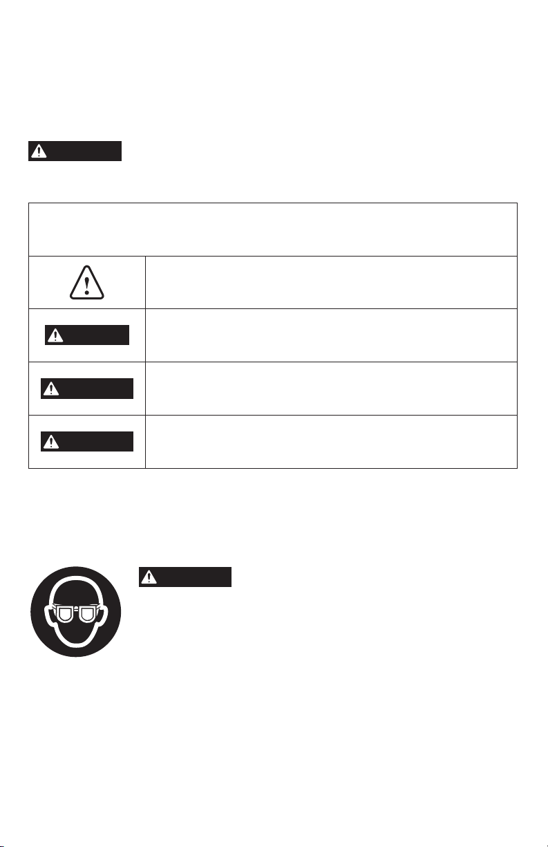
This is the safety alert symbol. It is used to alert you to potential
personal injury hazards. Obey all safety messages that follow this
symbol to avoid possible injury or death.
DANGER indicates a hazardous situation which, if not avoided, will
result in death or serious injury.
WARNING indicates a hazardous situation which, if not avoided, could
result in death or serious injury.
CAUTION, used with the safety alert symbol, indicates a hazardous
situation which, if not avoided, will result in minor or moderate injury.
Damage Prevention and Information Messages
These inform the user of important information and/or instructions that could lead to equipment
or other property damage if they are not followed. Each message is preceded by the word
“NOTICE”, as in the example below:
NOTICE: Equipment and/or property damage may result if these instructions are not followed.
WARNING
in severe eye damage. Before beginning power tool operation, always
wear safety goggles or safety glasses with side shields and a full face
shield when needed. We recommend a Wide Vision Safety Mask for use
over eyeglasses or standard safety glasses with side shields. Always use
eye protection which is marked to comply with ANSI Z87.1.
The operation of any power tools can result in
objects being thrown into your eyes, which can result
foreign
5

SYMBOLS (CONTINUED)
IMPORTANT: Some of the following symbols may be used on your tool. Please study them
and learn their meaning. Proper interpretation of these symbols will allow you to operate the
tool better and more safely.
Symbol Name Designation/Explanation
V Volts Voltage (potential)
A Amperes Current
Hz Hertz Frequency (cycles per second)
W Watt Power
kg Kilograms Weight
min Minutes Time
s Seconds Time
Ø Diameter Size of drill bits, grinding wheels, etc.
n
0
n Rated speed Maximum attainable speed
…/min
0 Off position Zero speed, zero torque...
1,2,3,…
I,II,III,
No load speed Rotational speed, at no load
Revolutions or reciprocation
per minute
Selector settings
Innitely variable selector
with off
Arrow Action in the direction of arrow
Alternating current Type or a characteristic of current
Direct current Type or a characteristic of current
Alternating or direct current Type or a characteristic of current
Class II tool
Revolutions, strokes, surface speed,
orbits, etc. per minute
Speed, torque or position settings. Higher
number means greater speed
Speed is increasing from 0 setting
Designates Double Insulated Construction
tools.
Earthing terminal Grounding terminal
Read manual symbol Alerts user to read manual
Wear eye protection symbol Alerts user to wear eye protection
6

SYMBOLS (CERTIFICATION INFORMATION)
IMPORTANT: Some of the following symbols for certication information may be used on your
tool. Please study them and learn their meaning. Proper interpretation of these symbols will
allow you to operate the tool better and more safely.
Symbol Designation/Explanation
This symbol designates that this tool is listed by Underwriters Laboratories.
This symbol designates that this tool is recognized by Underwriters
Laboratories.
This symbol designates that this tool is listed by Underwriters
Laboratories, to United States and Canadian Standards.
This symbol designates that this tool is listed by the Canadian
Standards Association.
This symbol designates that this tool is listed by the Canadian
Standards Association, to United States and Canadian Standards.
This symbol designates that this tool is listed by the Intertek Testing
Services, to United States and Canadian Standards.
This symbol designates that this tool complies to NOM Mexican
Standards.
7
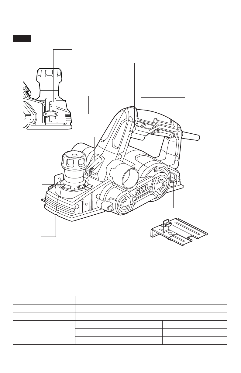
GET TO KNOW YOUR PLANER
AC Planer
Fig. 1
Rabbeting-depth
stop
Lock-off Button
Dust/ChipExtraction Guide
Switch
Cutting-DepthAdjustment
Knob
Cutting-Depth
Scale
V-groove
Locking Knob (x2)
ON/OFF Switch
Dust/ChipExtraction Ports
(x2)
Blade-change
Wrench
Edge Guide
SPECIFICATIONS
Rating 120V a.c. 60Hz
Input 6.5A
No-load speed 16000 /min
Planing width 3-1/4’’ (82mm)
Planing capacity
8
Planing depth 5/64’’ (2mm)
Rabbeting depth 5/16’’ (8mm)
OPERATING INSTRUCTIONS
WARNING
safety measures reduce the risk of starting the tool accidentally.
WARNING
result in serious personal injury.
WARNING
is misuse and could result in a hazardous condition leading to possible serious injury.
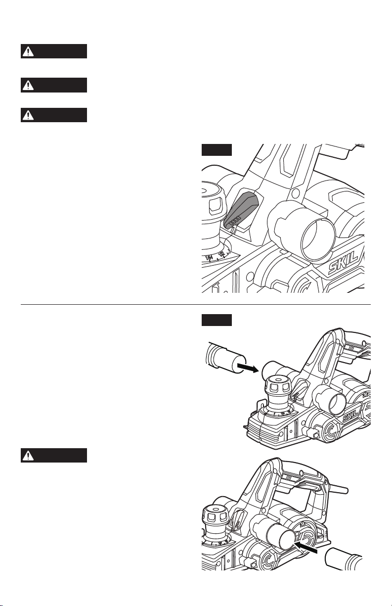
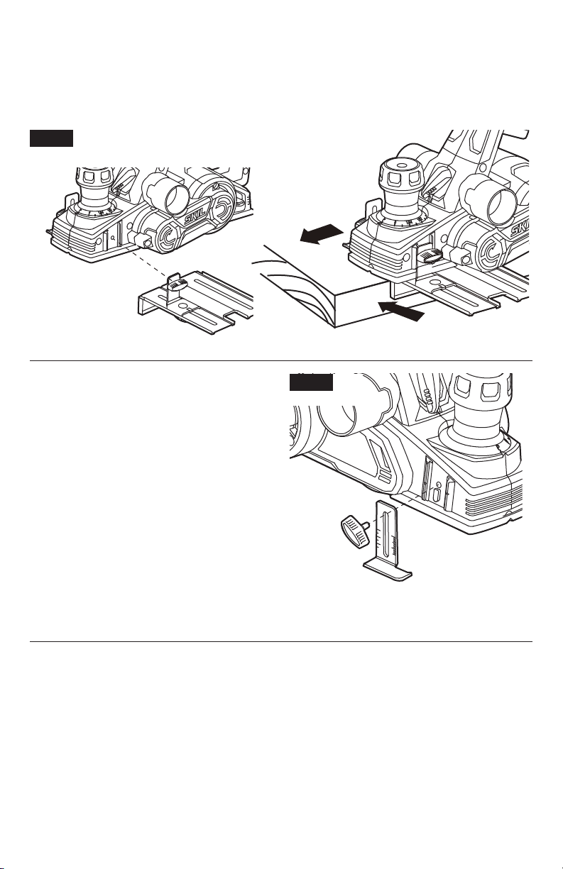
Dust/Chip Extraction Guide
Disconnect the plug from the power source before performing any
assembly, adjustments or changing accessories. Such preventive
If any parts are damaged or missing, do not operate this tool until the
parts are replaced. Use of this tool with damaged or missing parts could
Do not attempt to modify this tool or create accessories not
recommended for use with this tool. Any such alteration or modication
Fig. 2
Switch (Fig. 2)
Move the switch to the left to cause chips to be
discharged to the left;
Move the switch to the right to cause chips to
be discharged to the right.
Move the switch as your need.
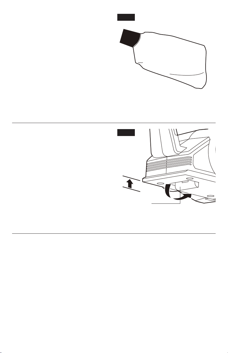
Dust/Chip Extraction (Fig.3)
Your tool is equipped with two dust/chipextraction ports, which may be used with a
vacuum adapter or a dust bag to keep your
work environment cleaner.
Firmly attach the vacuum adapter or dust
bag to the extraction port. A workshop dustextraction system or a household vacuum
cleaner can be connected to the vacuum
adapter for the efficient removal of dust and
shavings.
The vacuum adapter will t 1-1/4” hoses.
WARNING
dust/chip extraction ports while knives are
rotating.
Do not attempt to remove
any obstructions from the
Fig. 3
9
Dust Bag (Fig.4)
Attach the dust bag to the dust/chip-extraction
port for smaller jobs.
Also wear a suitable dust mask, as there may
be some residual airborne dust particles in the
area.
To attach the dust bag: Align the raised
emboss on the dust bag with the groove in the
extraction port and slide the dust bag into the
port. Then rotate the dust bag towards the front
of tool to lock it in place.
Empty the dust bag: Empty the dust bag by
unzipping the bag and then gently tapping the
bag to remove the dust. For a more thorough
cleaning of the dust bag, slip the bag off of the frame and turn bag inside out. Use a soft brush
to brush the dust off of the lining.
Fig. 4
Park Rest (Fig.5)
The park rest swings down to help keep the
blade from coming into contact with the work
surface when the planer is not in use.
The tool park rest was designed to
automatically swing up and out of the way
when the back of the planer crosses the
leading edge of the workpiece.
Fig. 5
Park Rest
10
Edge Guide (Fig.6)
a. Remove the locking knob and slide the edge guide into the planer.
b. Replace the locking knob and rmly tighten it.
c. Loosen the locking nut and slide the edge guide to the desired position. Securely tighten the
locking nut.
Fig. 6
Rabbeting-Depth Stop (Fig.7)
The rabbeting-depth stop allows the user to
set any rabbeting depth from 0 to 5/16 inch (8
mm).
For best results, it is important that the blade
be properly aligned with the front base of the
tool. The width of the rabbet is controlled by
the edge guide. The final depth is achieved
by repeating the planning procedure until the
rabbeting-depth stop contacts the workpiece.
To setting the rabbeting depth:
a. Loosen the locking knob and set the desired
rabbet depth by aligning the depth scale on
the rabbeting-depth stop with the indicator
line.
b. Securely tighten locking nut.
Fig. 7
11
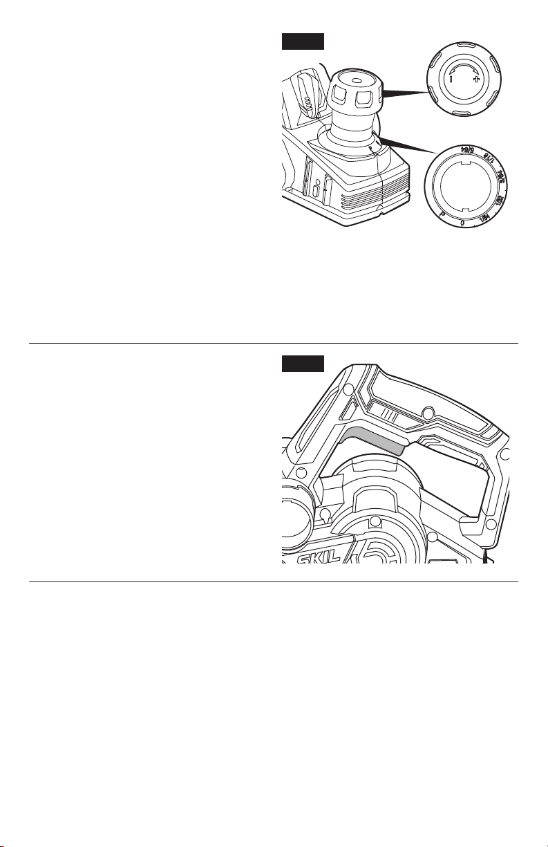
Adjusting the Depth of Cut (Fig.8)
The proper cutting depth should be determined
according to the hardness, gumminess or
moisture content of the material being cut, as
well as the feed rate, and is largely a matter of
experience.
Rotate the depth adjustment knob clockwise
for a deeper cut and counterclockwise for a
shallower cut.
The numbers on the cutting depth scale
indicate the depth of cut, e.g., when 1/64’’ is
next to the pointer on the front of the planer,
the depth of cut is approximately 1/64’’.
If it is necessary to more accurately determine
the depth of cut, plane a scrap piece of wood, measure the difference in thickness and adjust
the setting.
NOTICE: Always set the depth adjustment knob at the “P” position when the tool is not in use.
This retracts the planer blade, allowing the power tool to be placed down without the danger of
causing damage to the workpiece or the planer blade.
Fig. 8
Turning ON and OFF (Fig.9)
a. Connect the power cord of your planer to a
standard household power outlet.
b. To turn the planer ON, hold the tool with both
hands, push in the lock-off button rst, and
then press the on/off trigger switch.
c. To turn the planer OFF, release the trigger
switch.
Fig. 9
12

Planing
Fig. 10
WARNING
Hold the tool with both
hands while starting the
tool, since torque from the motor can cause
the tool to twist.
WARNING
Wherever possible, clamp
the workpiece to a
workbench or clamping table.
a. Unplug the planer and adjust the edge guide
and the cutting depth as appropriate.
b. Clamp the workpiece securely on a
workbench.
c. Connect the power cord of your planer to a
standard household power outlet.
d. While standing comfortably, hold the planer rmly with both hands (Fig.10).
e. Place the front base of the planer against the workpiece surface without the blade making
any contact with the workpiece.
f. Turn on the tool, allow it to reach full speed, and guide the tool with even feed over the
surface to be planed.
g. Move the tool gently forward, applying pressure on the front of the tool at the beginning of
the planing pass and pressure at the rear of the tool at the end of the planing pass.
h. Push the planer beyond the edge of the workpiece without tilting it downwards.
NOTICE:
•
The rate of planing and the depth of cut determine the quality of the cut. For rough cutting,
you can increase the depth of cut. To achieve a smooth cut, you will need to reduce the
depth of cut and advance the planer slowly across the workpiece and make successive,
shallow cuts, as needed.
•
The proper feed rate will depend on the type of material being cut and the depth of the cut.
When planing hard materials (e.g., hardwood), as well as when utilizing the maximum planer
width, set only low planing depths and reduce the planer feed as required.
•
Practice first on a scrap piece of material to gauge the correct feed rate and the cutting
depths.
•
Planing is easier if you slightly incline the workpiece so that you plane “downhill”.
•
Moving the planer too quickly may cause a poor quality of cut and can damage the blades or
the motor. Moving the planer too slowly may burn or mar the workpiece.
•
Before turning off the tool, lift it from the workpiece.
13

Chamfering (Fig.11)
The “V” groove in the front base of the tool
allows quick and easy chamfering of workpiece
edges.
a. Place the “V” groove over the edge to be
chamfered. Be sure the blades are not
touching the workpiece.
b. Position the “V” groove absolutely at on the
edge to be beveled.
c. Grasp the tool rmly with both hands, turn
the tool on and push the planer forward with
steady pressure on the front base of the tool.
Fig. 11
14

MAINTENANCE
WARNING
To avoid accidents always disconnect the tool from the power supply
before cleaning or performing any maintenance.
Planer Blades
The planer blades have two cutting edges and may be reversed. When both cutting edges are
dull, the planer blade must be replaced.
The planer blades may not be re-sharpened. Do not attempt to sharpen or use re-sharpened
blades of any kind.
Use only blades designated for use with this model, because other blades will cause vibration,
decrease performance and may not clamp securely in the blade holder.
Replacing the Planer Blades (Fig.12)
WARNING
•
When installing blades, rst disconnect the tool from the power supply, then clean out
all chips and/or foreign matter adhering to the blade holder and the clamping element.
Use blades of the same dimensions and weight, or else the holder will oscillate and
vibrate, causing poor planing action and tool breakdown.
•
Tighten the clamping screws carefully when attaching the blades to the planer. A
loose clamping screw could be extremely dangerous. Regularly check and ensure
that the clamping screws are securely tightened.
•
Be cautious when replacing the planer blades. Do not grasp the planer blades by the
cutting edges. Injury may result due to the sharp cutting edges of the planer blades.
To remove the old planer blades:
a. Disconnect the plug from the power source.
b. Place the planer upside down on a at surface.
c. Loosen the three clamping screws with the wrench that is provided.
d. Push the blade sideways out of the blade holder. A piece of wood may be used for this
purpose.
15
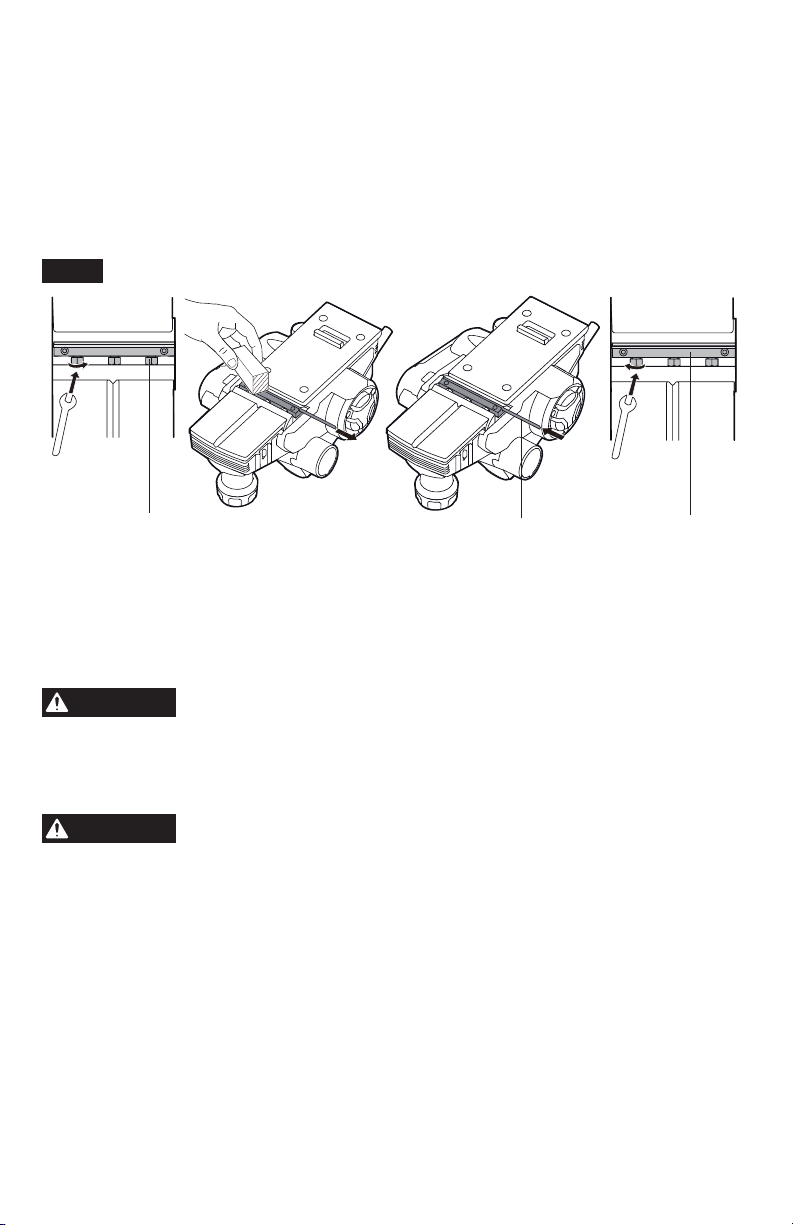
To install planer blades:
a. Disconnect the plug from power source.
b. Place the planer upside down on a at surface.
c. Clean all surfaces before installing the new blade or reversing the old blade, as this will
ensure an accurate blade setting and proper tool performance.
d. Slide the blade into the blade holder of the clamping element. The blade groove must
engage with the blade holder.
e. Tighten the three clamping screws again with the wrench (provided).
Fig. 12
Clamping Screws (x3) Blade Blade Holder
NOTICE: Your planing surface will end up rough and uneven unless the blades are set
properly and securely. The blades must be mounted so that the cutting edge is absolutely
level relative to the surface of the front and rear base.
Service
CAUTION
cause serious hazard. We recommend that all tool service be performed by a SKIL Factory
Service Center or Authorized SKIL Service Station.
Preventive maintenance performed by unauthorized personnel may
result in misplacing of internal wires and components which could
General Maintenance
CAUTION
Periodically inspect the entire product for damaged, missing, or loose parts such as screws,
nuts, bolts, caps, etc. Tighten securely all fasteners and caps and do not operate this product
until all missing or damaged parts are replaced. Please contact customer service or an
authorized service center for assistance.
When servicing, use only identical replacement parts. Use of any
other parts could create a hazard or cause product damage.
Carbon Brushes
The brushes and commutator in your tool have been engineered for many hours of
dependable service. To maintain peak efciency of the motor, we recommend that the brushes
be examined every two to six months. Only genuine SKIL replacement brushes specially
designed for your tool should be used.
16

Cleaning
WARNING
Ventilation openings and switch levers must be kept clean and free of foreign matter. Do not
attempt to clean by inserting pointed objects through openings.
WARNING
ammonia and house hold detergents that contain ammonia.
The tool may be cleaned most effectively with compressed dry air. Always
wear safety goggles when cleaning tools with compressed air.
Certain cleaning agents and solvents damage plastic parts. Some of
these are: gasoline, carbon tetrachloride, chlorinated cleaning solvents,
Storage
Store the tool indoors in a place that is inaccessible to children. Keep away from corrosive
agents.
Extension Cords
WARNING
tool must be used. This will prevent excessive voltage drop, loss of power or
overheating. Grounded tools must use 3-wire extension cords that have 3-prong plugs
and receptacles.
NOTICE: The smaller the gauge number, the heavier the cord.
If an extension cord is necessary, a cord with adequate size
conductors that is capable of carrying the current necessary for your
RECOMMENDED SIZES OF EXTENSION CORDS 120 VOLT
ALTERNATING CURRENT TOOLS
Tool’s Ampere Rating Cord Size in A.W.G Wire sizes in mm
3-6
6-8
8-10
10-12
12-16
Cord length in feet
25 50 100 150
18 16 16 14
18 16 14 12
18 16 14 12
16 16 14 12
14 12 - -
Cord length in meters
15 30 60 120
0.75 0.75 1.5 2.5
0.75 1.0 2.5 4.0
0.75 1.0 2.5 4.0
1.0 2.5 4.0 -
- - - -
2
TROUBLESHOOTING
Problem Cause Remedy
The motor does not start. 1. The tool is not connected to a
Planer does not plane
properly.
The motor is overheating. Cooling vents may be obstructed
power source.
2. The lock-off button is not
depressed before squeezing
the on/off switch.
1. The blade is dull.
2. Blades are not installed
correctly.
by dust or other obstacles
1 Connect the tool to a power
source.
2. Press down the lock-off
button and hold it, then
depress the switch to turn
on the planer.
1. Replace the blade.
2. Install the blades correctly
(see Installing Planer
Blades)
Clean and clear vents. Do
not cover with hand during
operation.
17

LIMITED WARRANTY OF SKIL CONSUMER PORTABLE,
BENCHTOP AND HD AND SHD HEAVY DUTY POWER TOOLS
Chervon North America (“Seller”) warrants to the original purchaser only, that all SKIL
consumer portable, benchtop and HD and SHD Heavy Duty power tools will be free from
defects in material or workmanship for a period of one year from date of purchase. SKIL
Benchtop and consumer portable power tool models will be free from defects in material or
workmanship for a period of ninety days if the tool is used for professional use.
SELLER’S SOLE OBLIGATION AND YOUR EXCLUSIVE REMEDY under this Limited
Warranty and, to the extent permitted by law, any warranty or condition implied by law,
shall be the repair or replacement of parts, without charge, which are defective in material
or workmanship and which have not been misused, carelessly handled, or misrepaired by
persons other than Seller or Authorized Service Station. To make a claim under this Limited
Warranty, you must return the complete product, transportation prepaid, to any SKIL Factory
Service Center or Authorized Service Station. For Authorized SKIL Power Tool Service
Stations, please visit www.Registermyskil.com or call 1-877-SKIL-999 (1-877-754-5999).
THIS LIMITED WARRANTY DOES NOT APPLY TO ACCESSORY ITEMS SUCH AS
CIRCULAR SAW BLADES, DRILL BITS, ROUTER BITS, JIGSAW BLADES, SANDING
BELTS, GRINDING WHEELS AND OTHER RELATED ITEMS.
ANY IMPLIED WARRANTIES SHALL BE LIMITED IN DURATION TO ONE YEAR FROM
DATE OF PURCHASE. SOME STATES IN THE U.S., SOME CANADIAN PRO V I NCES DO
NOT ALLOW LIMITATIONS ON HOW LONG AN IMPLIED WARRANTY LASTS, SO THE
ABOVE LIMITATION MAY NOT APPLY TO YOU.
IN NO EVENT SHALL SELLER BE LIABLE FOR ANY INCIDENTAL OR CONSEQUENTIAL
DAMAGES (INCLUDING BUT NOT LIMITED TO LIABILITY FOR LOSS OF PROFITS)
ARISING FROM THE SALE OR USE OF THIS PRODUCT. SOME STATES IN THE U.S.
AND SOME CANADIAN PROVINCES DO NOT ALLOW THE EXCLUSION OR LIMITATION
OF INCIDENTAL OR CONSEQUENTIAL DAMAGES, SO THE ABOVE LIMITATION OR
EXCLUSION MAY NOT APPLY TO YOU.
THIS LIMITED WARRANTY GIVES YOU SPECIFIC LEGAL RIGHTS, AND YOU MAY ALSO
HAVE OTHER RIGHTS WHICH VARY FROM STATE TO STATE IN THE U.S., PROVINCE
TO PROVINCE IN CANADA AND FROM COUNTRY TO COUNTRY.
THIS LIMITED WARRANTY APPLIES ONLY TO PRODUCTS SOLD WITHIN THE UNITED
STATES OF AMERICA, CANADA AND THE COMMONWEALTH OF PUERTO RICO. FOR
WARRANTY COVERAGE WITHIN OTHER COUNTRIES, CONTACT YOUR LOCAL SKIL
DEALER OR IMPORTER.
© Chervon North America, 1203 E. Warrenville Rd, Naperville, IL 60563.
04/19
18
 Loading...