

Skil ME981901 Owner's Manual
1-877-SKIL-999 OR www.skiltools.com
WARNING: To reduce the risk of injury, the user must read and understand the
Operator’s Manual before using this product. Save these instructions for future reference.
AVERTISSEMENT : Afin de réduire les risques de blessure, l’utilisateur doit lire et
comprendre le guide d’utilisation avant d’utiliser cet article. Conservez le présent guide
afin de pouvoir le consulter ultérieurement.
ADVERTENCIA : Para reducir el riesgo de lesiones, el usuario debe leer y comprender
el Manual del operador antes de utilizar este producto. Guarde estas instrucciones para
consultarlas en caso sea necesario.
Owner’s Manual
Guide d’utilisation
Manual del propietario
For Customer Service
Pour le service à la clientèle
Servicio al cliente
Model/ Modelo/ Modèle: #ME981901
100ft Laser Distance Measurer & Level
Mesure de distances jusqu’à 100 pi et niveau
Medidor de distancia y nivel láser hasta 100 pies

2
TABLE OF CONTENTS
General Laser Tool Safety Warnings .................3-4
FCC Statement ...................................4-5
Safety Rules Of Connecting External Power Tool ........5
Symbols ........................................6-9
Get to Know Your Laser Tool ..................... 10-11
Packing List ......................................11
Specications ....................................12
Operating Instructions ..........................13-26
Maintenance ......................................27
Trouble Shooting ............................... 28-29
Limited Warranty Of Skil Consumer Tools .............31
3
GENERAL LASER TOOL SAFETY WARNINGS
READ ALL INSTRUCTIONS BEFORE USING THE
TOOL!
WARNING
LASER
RADIATION.
Do
not stare into beam. Class II laser
product. Turn the laser beam on only
when using this tool.
Do not remove or deface any
product labels.
Avoid direct eye exposure.
The laser
beam can cause ash blindness.
Do not operate the tool around children
or allow children to operate the tool.
Do not place the tool in a position
that may cause anyone to stare at the
laser beam, whether intentionally or
unintentionally.
Do not use on surfaces such as
sheet steel that have shiny, reective
surfaces. The shiny surface could
reect the beam back at the operator.
Always turn the laser tool off
when not in use.
Leaving the tool
on increases the risk of someone
inadvertently staring into the laser
beam.
Do not attempt to modify the
performance of this laser device in any
way. This may result in a dangerous
exposure to laser radiation.
CAUTION/PRECAUCIÓN/ATTENTION
AVOID EXPOSURE/EVITE LA EXPOSICIÓN/
ÉVITEZ L’EXPOSITION
LASER RADIATION IS EMITTED FROM THIS
APERTURE
LA RADIACIÓN LÁSER SE EMITE DE ESTA
ABERTURA
CET OUTIL PRODUIT UN RAYONNEMENT LASER
LASER RADIATION-DO NOT STARE
INTO BEAM
RADIACIÓN LÁSER: NO MIRE
DIRECTAMENTE EL RAYO
RAYONNEMENT LASER – NE FIXEZ
PAS DES YEUX LE RAYON LASER
CAUTION: Risk of re and burns. Do not open,
crush, heat above 100° C (212° F) or incinerate.
PRECAUCIÓN : Riesgo de incendio y
quemaduras. No abra, triture, permita que esté a
mayor temperatura que 100° C (212 °F) ni
incinere.
ATTENTION : Risque d’incendie et de brûlures.
N’ouvrez pas le produit, ne l’écrasez pas, ne le
chauffez pas à plus de 100 ºC (212°F) et ne
l’incinérez pas.
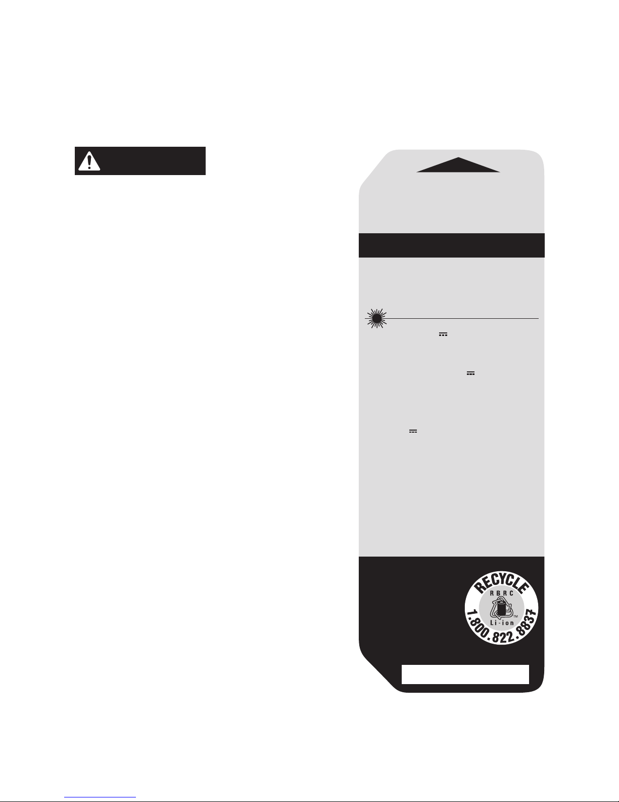
635nm, OUTPUT < 1mW/CLASS II LASER
PRODUCT 3.7V 500mAh Li-Polymer
COMPLIES WITH 21 CFR PARTS 1040.10 AND
1040.11
PRODUCTO LÁSER CON SALIDA < 1mW.
CLASE II, 635nm, 3,7V 500mAh polímero
de litio
CUMPLE CON LAS SECCIONES 21 CFR
1040.10 Y 1040.11
635nm, SORTIE < 1 mW/PRODUIT LASER DE
CLASSE II Pile au lithium-polymère de
3,7 V, 500 mAh
CONFORME AUX NORMES 21CFR ARTICLES
1040.10 ET 1040.11
MADE IN CHINA /
HECHO EN CHINA /
FABRIQUÉ EN CHINE
SERIAL NO./ SERIE NO./ NUMÉRO DE SÉRIE
CAN ICES-3(B)/NMB-3(B)
Model / Modelo /
Modèle: ME981901
1.85Wh

4
Do not attempt to repair or disassemble the tool. If unqualied
persons attempt to repair this product, serious injury may occur. Any
repair required on this laser product should be performed only by
qualied service personnel.
Use of other accessories that have been designed for use with other
laser tools could result in serious injury.
Do not operate the tool outdoors.
Do not place or store tool under extreme temperature conditions.
FCC STATEMENT
The manufacturer is not responsible for radio interference caused
by unauthorized modications to this equipment. Such modications
could void the user’s authority to operate the equipment.
This device complies with Part 15 of the FCC Rules. Operation is
subject to the following two conditions:
(1) This device may not cause harmful interference.
(2) This device must accept any interference received, including
interference that may cause undesired operation.
Changes or modications not expressly approved by the party
responsible for compliance could void the user’s authority to operate
the equipment.
NOTE:
This equipment has been tested and found to comply with
the limits for a Class B digital device, pursuant to Part 15 of the FCC
Rules. These limits are designed to provide reasonable protection
against harmful interference in a residential installation. This
equipment generates, uses, and can radiate radio frequency energy
and, if not installed and used in accordance with the instructions,
may cause harmful interference to radio communications. However,
there is no guarantee that interference will not occur in a particular
installation. If this equipment does cause harmful interference to
radio or television reception, which can be determined by turning
the equipment off and on, the user is encouraged to try to correct
the interference by one or more of the following measures:

5
•
Reorient or relocate the receiving antenna.
•
Increase the separation between the equipment and receiver.
•
Connect the equipment into an outlet on a circuit different from
that to which the receiver is connected.
•
Consult the dealer or an experienced radio/TV technician for help.
DANGER
People with electronic devices, such as
pacemakers, should consult their physician(s)
before using this product. Operation of electrical equipment in close
proximity to a heart pacemaker could cause interference or failure of
the pacemaker.
SAFETY RULES OF CONNECTING EXTERNAL
POWER TOOL
WARNING
Read and follow all instructions below
before connect with external power supply
such as AC supply and DC mobile power.
Failure to follow all
instructions below may result in electric shock, explosion, re and/or
serious personal injury.
Only choose the qualied and legal adapter which output voltage is
5V and output electricity is ≥0.5A.
Conrm the adapter suits the AC supply before do connecting.
Conrm the mobile power is qualied and legal , the output voltage
is 5V and the output electricity is ≥0.5A before do connecting.
Keep the adapter clean. Check the adapter, cable and plug before
do connecting. If damage is detected, do not use or repair by
yourself, change the damaged one or get repairs performed by
authorized service personnel, otherwise electric shock may occur.
Do not do connecting with AC supply on easily inammable surfaces
(e.g., paper, textiles, etc.) or surroundings. The heating of the
adapter during using may pose a re hazard.
Children or persons with physical, sensory or mental limitations
or lack of experience and knowledge are not capable of securely
operating the adapter unless they are being given supervision or
having been instructed by a responsible person.
6
SYMBOLS
Safety Symbols
The purpose of safety symbols is to attract your attention to
possible dangers. The safety symbols and the explanations with
them deserve your careful attention and understanding. The
symbol warnings do not, by themselves, eliminate any danger. The
instructions and warnings they give are no substitutes for proper
accident prevention measures.
WARNING
Be sure to read and understand all safety
instructions in this Operator’s Manual, including
all safety alert symbols such as “
DANGER
,” “
WARNING
,” and
“
CAUTION
” before using this tool. Failure to following all instructions
listed below may result in electric shock, re, and/or serious
personal injury.
The denitions below describe the level of severity for each
signal word. Please read the manual and pay attention to these
symbols.
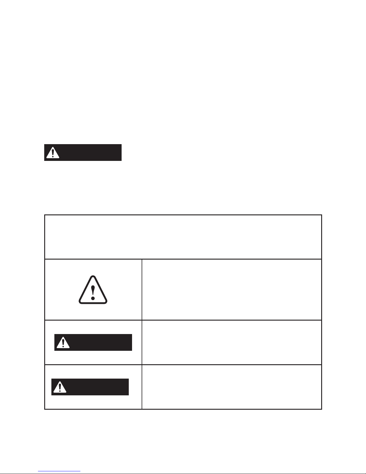
This is the safety alert symbol. It is
used to alert you to potential personal
injury hazards. Obey all safety
messages that follow this symbol to
avoid possible injury or death.
DANGER
DANGER indicates a hazardous
situation which, if not avoided, will
result in death or serious injury.
WARNING
WARNING indicates a hazardous
situation which, if not avoided, could
result in death or serious injury.
7
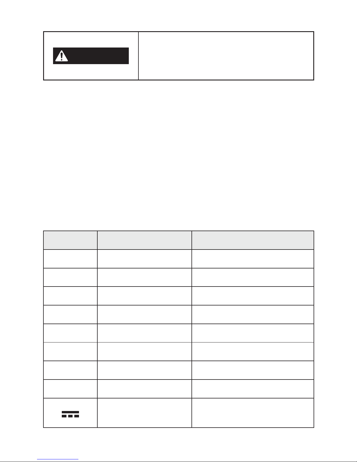
CAUTION
CAUTION, used with the safety alert
symbol, indicates a hazardous situation
which, if not avoided, will result in
minor or moderate injury.
Damage Prevention And Information Messages
These inform the user of important information and/or instructions
that could lead to equipment or other property damage if they are
not followed. Each message is preceded by the word “NOTICE”, as
in the example below:
NOTICE:
Equipment and/or property damage may result if these
instructions are not followed.
IMPORTANT:
Some of the following symbols may be used on
your tool. Please study them and learn their meaning. Proper
interpretation of these symbols will allow you to operate the tool
better and safer.
Symbol Name Designation/Explanation
V Volts Voltage (potential)
A Amperes Current
mW Milliwatt Power
kg Kilograms Weight
min Minutes Time
s Seconds Time
Wh Watt-hours Battery capacity
mAh Milliampere-Hours Battery capacity
Direct current
Type or a characteristic of
current

8
Symbol Name Designation/Explanation
Main Button Power/Measure/Unit button
UP Arrow Button Mode/Unit button
Down Arrow Button
Mode button besides
relative angle measurement
Full-battery indicator
Indicate the battery is fully
charged
Empty-battery
indicator
Indicate the battery is
exhausted
Distance reference
base indicator
Indicates that the
measurement is taken from
the rear of the tool
Laser indicator
Indicates that laser is turned
on
Single-distance
measure
Indicates enter the singledistance measurement
mode
Area measure
Indicates enter the area
measurement mode
Real time measure
Indicates enter the real-time
measurement mode
Indirect measure
Indicates enter the Indirect
measurement mode
Level measure
Indicates enter the digital
leveling mode
9
Symbol Name Designation/Explanation
CEC Energy
Efciency Logo
CEC certication logo for
battery charging system
Li-ion RBRC seal
Designates Li-ion battery
recycling program
Read manual symbol Alerts user to read manual

10
GET TO KNOW YOUR LASER TOOL
The tool is a combo tool for highly accurate measuring and leveling.
•
Measures distances from 1-100 feet with an accuracy of ±1/8
inch.
•
Measures distances and computes areas.
•
Real-time distance measuring.
•
Makes angle measurements with superior accuracy.
•
Quick indirect measurement of indirect distance and indirect
height.
•
Easy-to-read numbers and user-friendly interface in backlit
display.
•
Integrated, rechargeable Lithium battery.
11
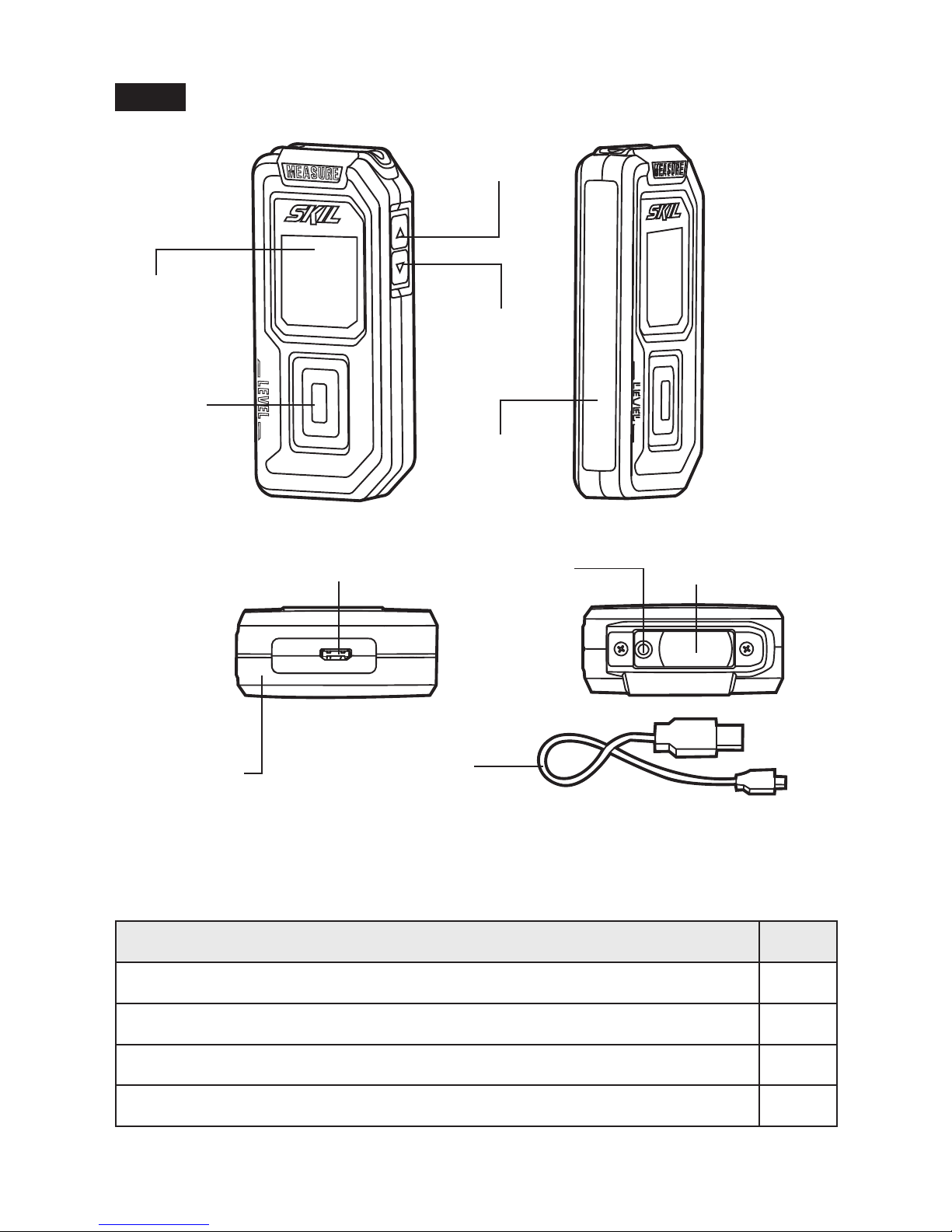
Fig. 1
LCD
Screen
Main
Button
Angle Base
Laser-Receiving
Lens
Micro USB Charging Port
Laser-Exit
Aperture
USB Charging
Cable
Distance
Reference
Base
UP Arrow
Button
Down Arrow
Button
PACKING LIST
PART NAME QTY
100ft Laser Distance Measurer & Level 1
USB Charging Cable 1
Soft Bag 1
Instruction Manual 1

12
SPECIFICATIONS
Battery voltage 500mAh 3.7 V Lithium
Laser
λ=635nm, Class II laser,Maximum laser
output < 1mw
Measuring range
(typically)*
Distances 1-100 feet (0.3-30 m)
Angles 0-90°
Measuring accuracy
(typically)*
Distances ±1/8 inch (±3 mm)
Angles ± 0.5°
Smallest unit displayed 1/16 inch (0.001 m)
Automatic switch off
Distances
Laser: 20 seconds
Measuring: 3 minutes
(calculating after the
laser turns off)
Angles Measuring: 6 minutes
Estimated battery life Up to 3000 single measurements
Optimum operating
temperature
+32°F to 104°F (0
o
C to 40oC)
Storage temperature -4°F to 170.6°F (-20
o
C to 77oC)
*Important: Under unfavorable conditions, such as in bright sunlight
or when measuring poorly reecting or very rough surfaces, the
tool’s measuring range and accuracy will be reduced.

13
OPERATING INSTRUCTIONS
WARNING
To reduce the risk of re, personal injury,
and product damage due to a short
circuit, never immerse your tool or charger in uid or allow
a uid to ow inside it.
Corrosive or conductive uids, such as
seawater, certain industrial chemicals, and bleach or bleach
containing products, etc., can cause a short circuit.
Charge The Tool
NOTE:
The tool is shipped partially charged; charge the battery
before rst use.
Optimum performance can be reached by recharging the tool
for approximately 2.5 hours after use. It is not recommended to
recharge the tool for more than 24 hours after each use.
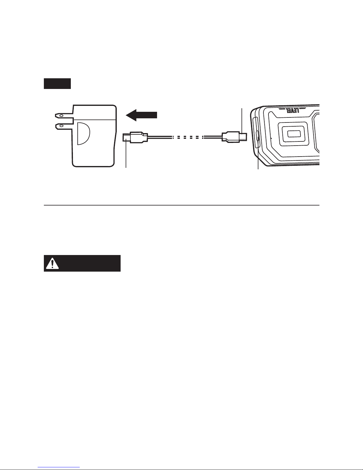
a. Insert the USB interface of the USB charging cable into the USB
port of the USB wall adapter (not included).
b. Insert the charging plug into charging port of the tool, making sure
that they are properly connected. (FIG. 2)
c. Connect the wall adapter (together with USB charging cable) to
the power outlet. The tool will turn on automatically. The battery
indicator will begin to icker on the LCD display to indicate that
the tool is charging.
14
When charging is complete, the full-battery indicator will appear
on the LCD screen. Remember to remove the USB charging cable
from tool. If the USB charging cable remains connected to the tool,
the tool will turn off approximately after half an hour.
Fig. 2
Charging Plug
Charging PortUSB Interface
Turn The Tool On And Off
Press the Main Button to turn on the tool. Press and hold the Main
Button for 1 second to turn off the tool.
WARNING
The laser will be automatically activated when
the tool is turned on. DO NOT place the
measuring tool in a position that may cause anyone to stare into the
laser intentionally or unintentionally. Serious eye injury could result.
NOTE:
When the tool is inactive for 3 minutes (after the laser has
turned off) in any mode except the digital leveling mode, it will
automatically turn off to save battery power. When in the digital
leveling mode, the tool will automatically turn off after 6 minutes
of inactivity, which is dened as the deviation (both positive and
negative) angle range not exceeding 1.5°.
15
Change The Measure Mode
Press the UP or Down Arrow Button to scroll through the following
modes:
•
Single-distance measurement
•
Area measurement
•
Real-time measurement
•
Indirect measurement
•
Digital leveling
Change the Unit of Measure (Single-Distance, Area,
Real Time, and Indirect Measurement)
Option 1
Main Button
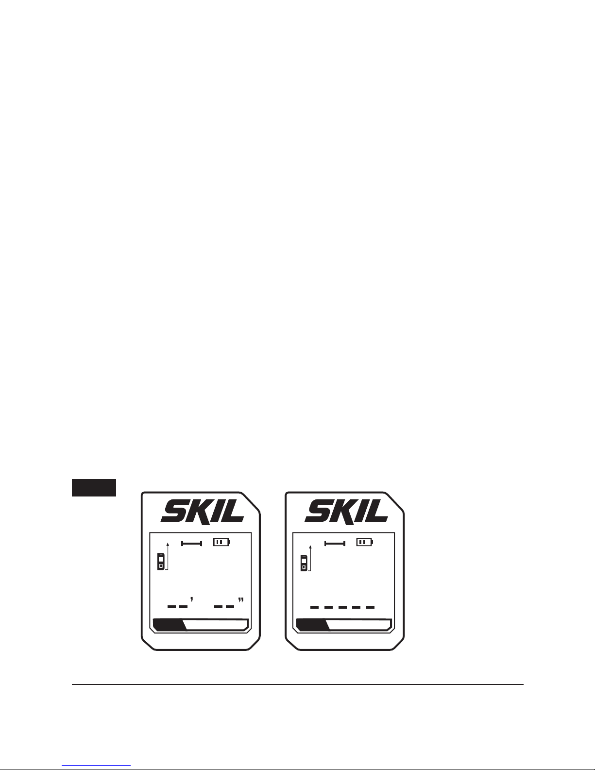
NOTE:
The tool defaults to feet and inches before the rst use.
Press and hold the Main Button to turn on the tool. Continue holding
for more than 2 seconds until the desired unit of measurement
(feet/inch or meters) is displayed on the screen (FIG. 3). When the
desired unit of measurement appears on the screen, release the
Main Button. After releasing the button, the tool turns itself on and
subsequent measurements will be displayed in the selected unit.
MODE
Distance
MODE
Distance
m
Fig. 3

16
Option 2
Press the Main Button to turn on the tool. Press and hold the UP
Arrow Button for 2 seconds until the desired unit of measurement
among the choices listed below is displayed on the screen.
Distance Area
Unit and
precision
0.000 m 0.000 m
2
0’ 00”
1/16
0.000 ft
2
0”
1/16
0.000 ft
2
0.000” 0.000 ft
2
NOTE:
Faulty measurements cannot be excluded when measuring
to different surfaces.
Among the problematic surfaces are:
•
Transparent surfaces (e.g., glass, water)
•
Reective surfaces (e.g., polished metal, glass)
•
Porous surface (e.g., insulation materials)
•
Structured surfaces (e.g., roughcast, natural stone)
If required, use a laser target plate (not included) on these surfaces.
Furthermore, faulty measurements are also possible when sighting
inclined target surfaces.
Air layers with varying temperatures or indirectly received reections
can affect the measured value.
NOTE:
When error messages occur in the LCD display, press any
button to go back to the initial measurement display.
NOTE:
When entering into the modes involve of distance
measuring, the distance measurement will be taken from the
Distance Reference Base of the tool.
17
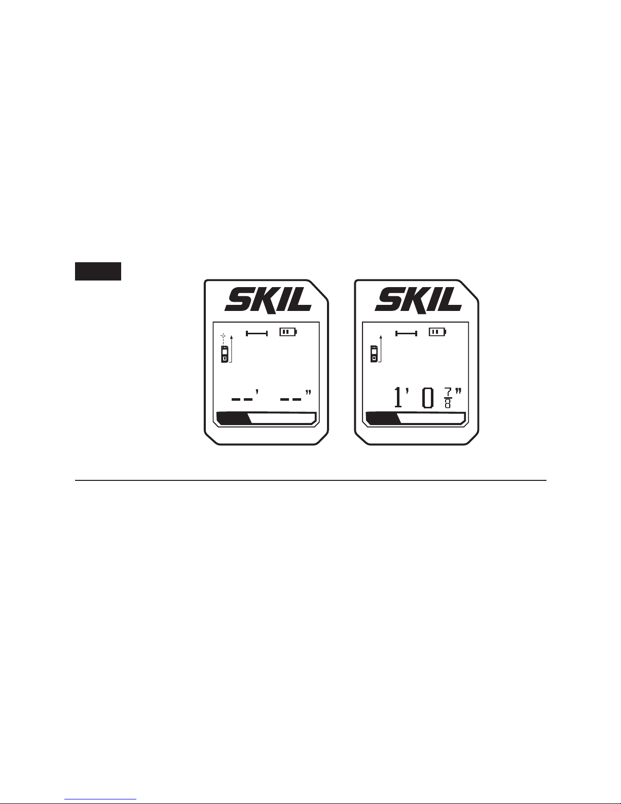
Single-Distance Measurement
a. Turn on the tool; the tool will default to the single-distance
measurement mode and the LCD will display “Distance” on the
lower right. The laser will turn on automatically and the laser
indicator will blink. (FIG. 4)
b. Aim the laser at the target to which you want to measure.
Press the Main Button to take a measurement. The resulting
measurement will be displayed on the LCD screen and the laser
will turn off automatically (FIG. 4).
MODE
Distance
MODE
Distance
Fig. 4
18
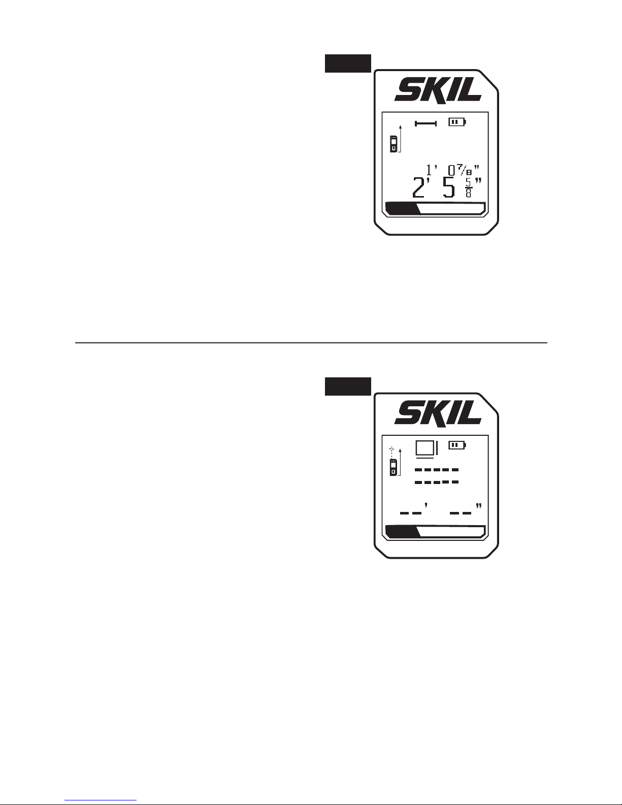
To take a second measurement:
a. Press the Main Button to turn
on the laser again; the rst
measurement will be displayed
in the upper row of the screen
(FIG. 5).
b. Press the Main Button again
to take a measurement. The
resulting second measurement
will be displayed in the lowest
row of the screen, and the laser will turn off automatically (FIG. 5).
NOTE:
When the laser is inactive for 20 seconds, it will
automatically turn off.
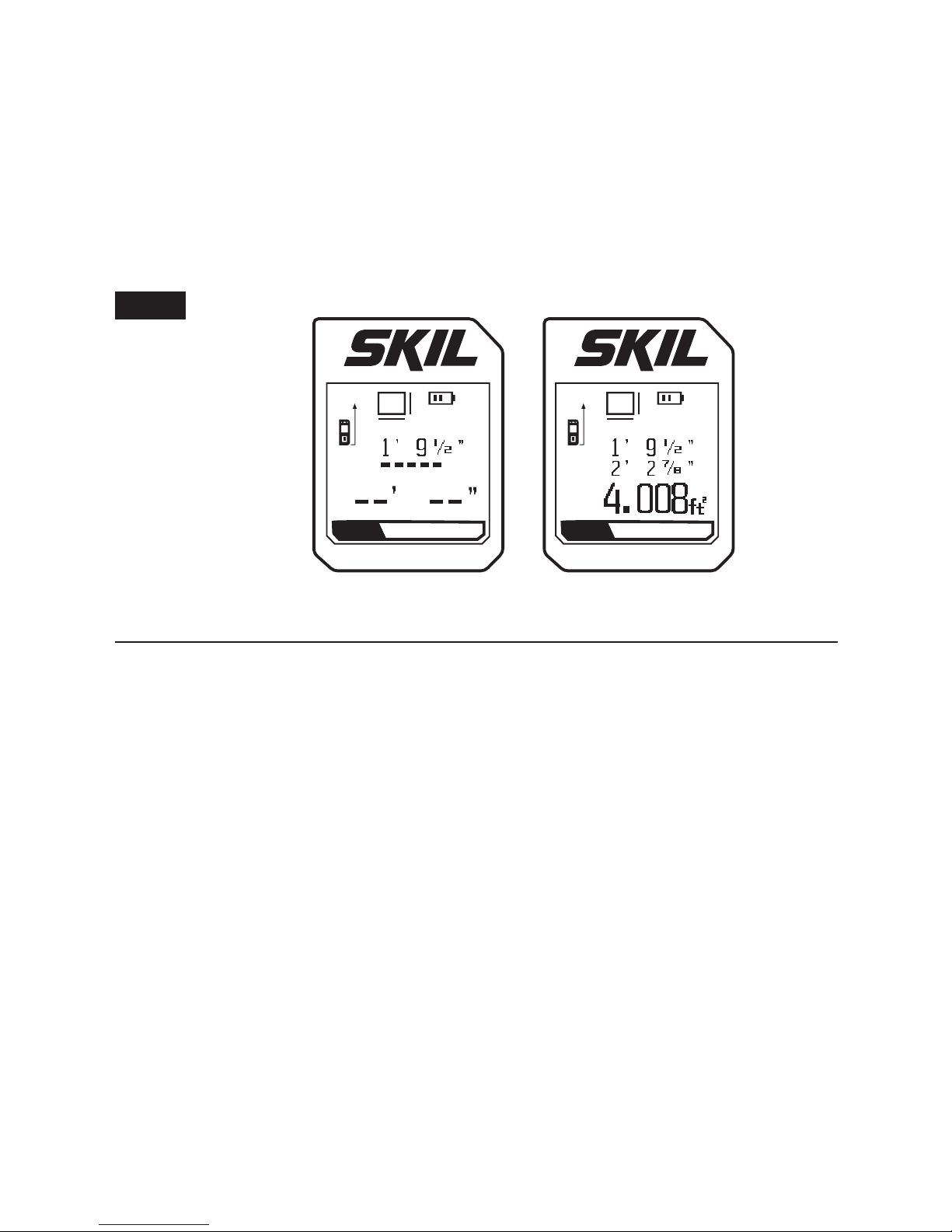
Area Measurement
a. Press UP Arrow Button or Down
Arrow Button to change the
mode to the area measurement.
The LCD will display “Area” on
the lower right (FIG. 6).
b. Press the Main Button to turn
on the laser if it is turned off; the
laser indicator will blink.
c. Position the tool to aim the laser
dot at the target representing the
rst dimension that you want to measure (e.g., length).
d. Press the Main Button to display the measured length in the rst
row of the screen.
e. Position the tool to aim the laser dot at the target representing the
second dimension that you want to measure (e.g., width).
MODE
Distance
Fig. 5
MODE
Area
Fig. 6
19
f. Press the Main Button again. The width will display in the second
row and the area computation will display in the lowest row of the
screen (FIG. 7). The laser will turn off automatically.
g. Press the Main Button again to make a new measurement.
NOTE:
When the laser is inactive for 20 seconds, it will
automatically turn off.
MODE
Area Area
MODE
Fig. 7
Real-Time Measurement
The real-time measurement function can be used for transferring
measurements, e.g., from construction plans. In the real-time
measure mode, the tool can be moved relative to the target and
will continuously update the displayed distance to the target as
the tool is moved. For example, the user can move from a wall to
a predetermined distance, during which time the actual, changing
measurement is displayed continuously.
a. Press UP Arrow Button or Down Arrow Button to change the
mode to the real-time measurement. The LCD will display “RealTime” on the lower right (FIG. 8).
b. Press the Main Button to turn on the laser if it is turned off; the
Laser Indicator will blink.
c. Press the Main Button to take the measurement; the beeper is
activated and the tool sounds.
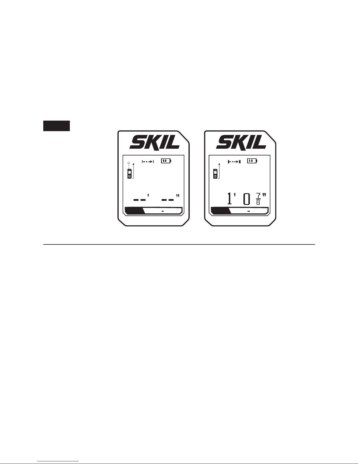
20
d. Move the tool until the required distance value is indicated at the
lower row on the LCD screen (FIG. 8).
NOTE:
Press the Main Button to stop the real-time measurement
during 3 minutes of operation.
Press the Main Button again to make a new measurement.
NOTE:
When the laser is inactive for 20 seconds, it will
automatically turn off
.
MODE MODE
Real Time Real Time
Fig. 8
21
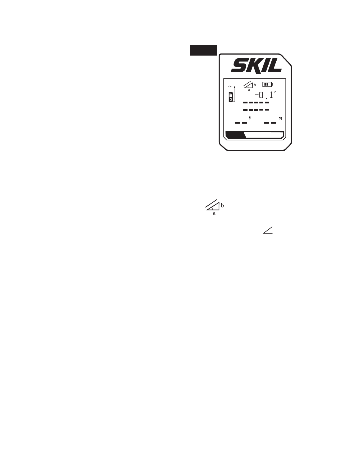
Indirect Measurement
In the Indirect Measurement mode,
the tool measures one angle and
one side of a right triangle and
used trigonometry to compute the
distance that cannot be measured
because of obstruction by an
obstacle or the unavailability of a
reecting target surface.
1. Press UP Arrow Button or Down
Arrow Button to change the
mode to the indirect measurement. The LCD will display “Indirect”
on the lower right.
2. Press the Main Button to turn on the laser if it is not turned on;
both the Laser Indicator and the icon
will blink. (FIG. 9)
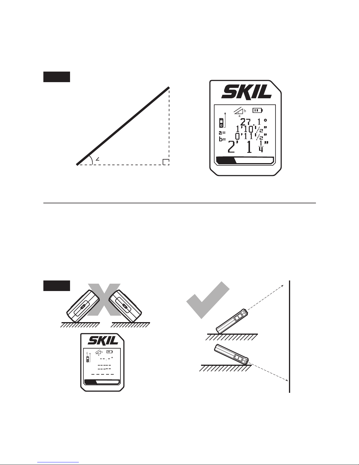
3. Position the tool with the Distance Reference Base on point A and
aim the laser at the target B. The real-time angle of
BAC will
automatically show in rst row of the display. (FIG. 10)
4. Without changing the measuring reference point of the tool in
position A, aim the laser at point B and press the Main Button.
Ensure that the tool is level and square when taking this
measurement.
The calculated length of AC will appear in the second row of the
screen with prex “a=”, The calculated length of BC will appear in
the third row of the screen with prex “b=”, and the measured length
of AB will appear in the lowest row of the screen (FIG. 10).
MODE
Indirect
Fig. 9
22
NOTE:
The calculated length AC(a) defaults to be absolutely level
and lengths AC(a) and BC(b) default to form a right angle of 90°.
(FIG. 10)
MODE
Indirect
BAC
A
B
C
a
b
Fig. 10
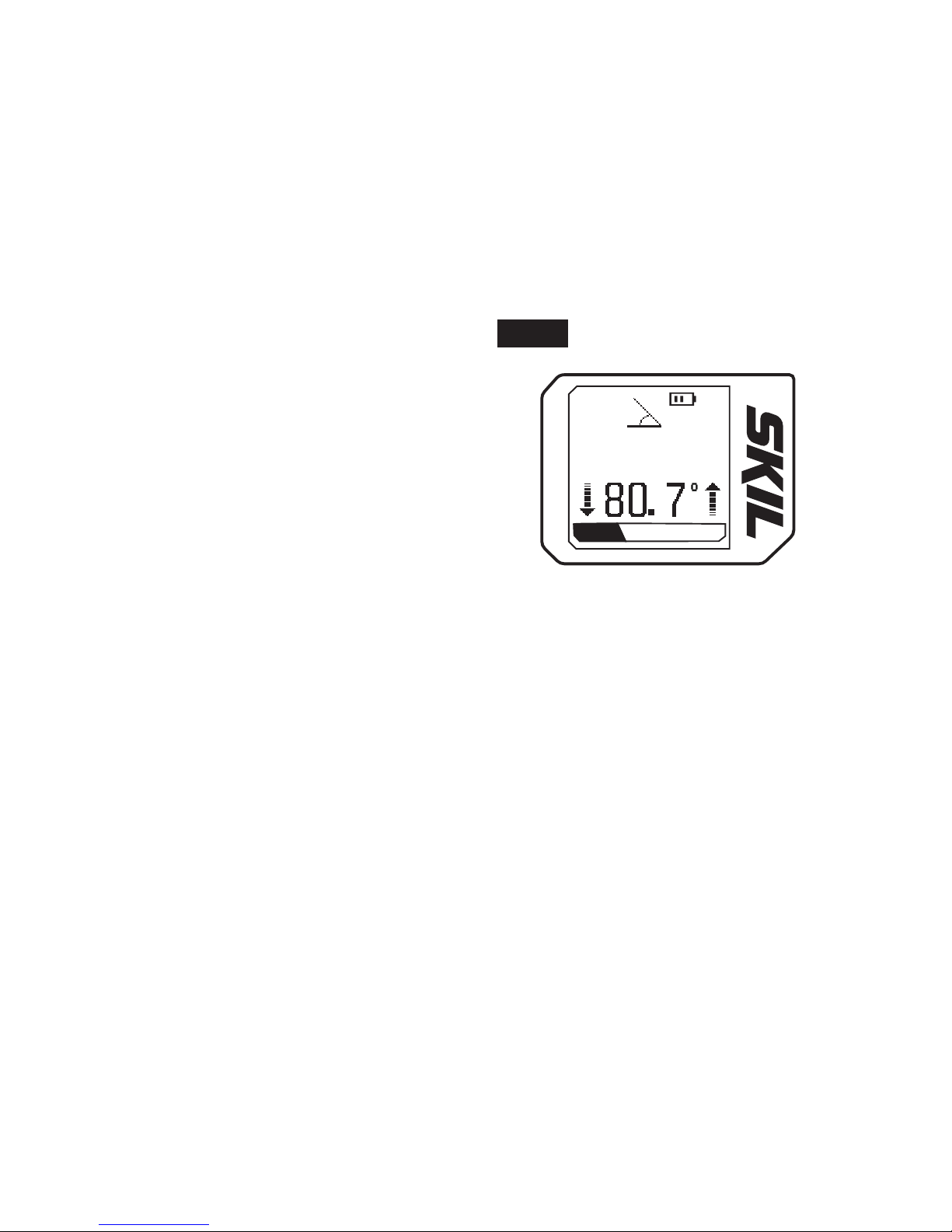
NOTE:
When the tool inclines to left or right in any position, the
LCD screen will show “--.-°” or an inaccurate angle measurement in
rst row of the display. Subsequent measurement will be showed or
calculated by error message or inaccurate value.
NOTE:
When the laser is inactive for 20 seconds, it will
automatically turn off.
X
MODE
Indirect
m
Fig. 11
23
Digital Leveling
NOTE:
Use the Angle Base as the standard testing base which will
be adhered on the working surface while measuring in this mode.
Only the measurements underneath this are considered to be
accurate.
Absolute Angle Measurement
Unlike common levels, this tool
makes 0-90° angle measurements with superior accuracy.
Press the UP Arrow Button or the
Down Arrow Button to change
the mode to digital leveling. The
LCD will display “Level” on the
lower right (FIG. 12).
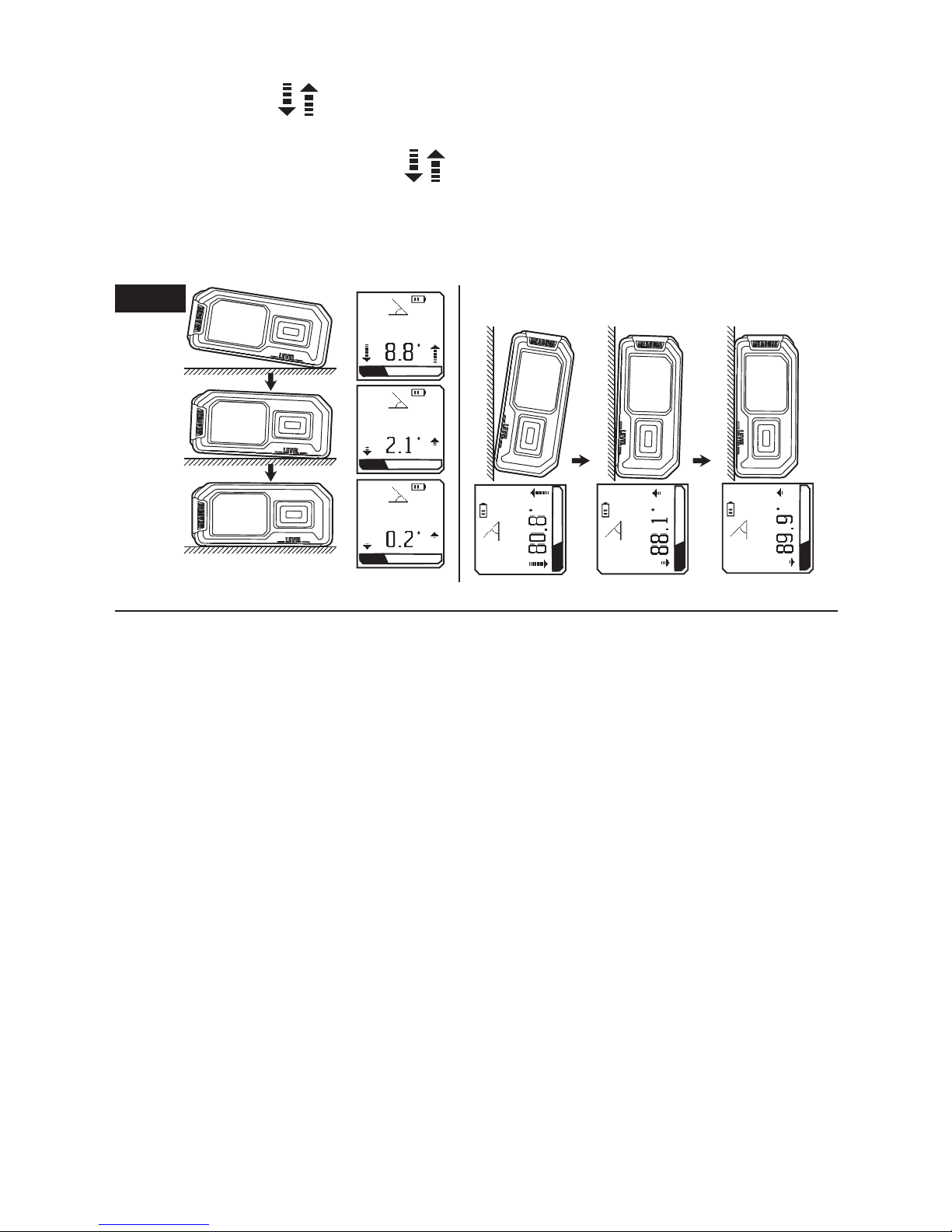
1. Place the tool’s Angle Base on
the surface to be measured. The
display indicates the difference,
in degrees, between that surface and absolute level.
2. To level the working surface, move the surface with the tool
on it until the readout is 0.0°, which indicates “level”.
3. To plumb the working surface, move the surface with the tool
on it until the readout is 90.0°.
NOTE:
The tool will only beep at 0°, 45° and 90°, with ±1°ac-
curacy. When deviation (positive or negative) is from 0.1 to 0.5
degree of one of the three angles, the tool will beep at a higher
frequently; from 0.6 to 1.0 degree of one of the three angles, the
tool will beep at a less frequently.
M O D E
Level
Fig. 12
24
NOTE:
Arrows
occur only when the deviation (positive or
negative) is between 0.1 to 10 degrees at 0° and 90°. The height
and direction of the arrows
on the LCD screen vary with the
angle relative to 0° or 90°, depending on the value and direction of
the deviations from them. Follow the arrow icons to ne tune the
position of the tool to level or plumb. (FIG. 13)
M O DE
Level
M O DE
Level
M O DE
Level
M O DE
Level
M O DE
Level
M O DE
Level
Fig. 13
Fine Turn to Level
Fine Turn to Plumb
Relative Angle Measurement
Use the relative-angle measurement to measure the angle
difference between two working surfaces.
1. Turn on the tool. Press the UP Arrow Button or Down Arrow
Button to change the mode to digital leveling. The LCD screen
indicates the absolute angle between true level and the working
surface.

25
2. Place the tool’s Angle Base
on the rst working surface.
Make sure that the tool remains
stationary and press the Down
Arrow Button for 1 second
to enter the relative angle
measurement mode. The current
angle will be set to 0.0°; the LCD
screen will display
(FIG. 14).
3. Place the tool’s Angle Base
on the second working surface. The relative angle between the
rst working surface and the second working surface will be
displayed.
4. Press the Down Arrow Button for 1 second again to release from
the mode; the icon
will disappear.
NOTE:
The tool will beep at the new reference value 0°, 45° and
90° in the same way as the absolute value 0°, 45° and 90° shown in
the Absolute Angle Measurement.
NOTE:
Arrows
will also display at the new reference value 0°
and 90° in the same way as the absolute value 0° and 90° shown in
the Absolute Angle Measurement.
NOTE:
When the tool inclines more than approximately 45° forward
or backward, the LCD screen will indicate “--.-°” (FIG. 15).
M O D E
Level
Fig. 15
Forward
Backward
M O DE
Level
Fig. 14
26
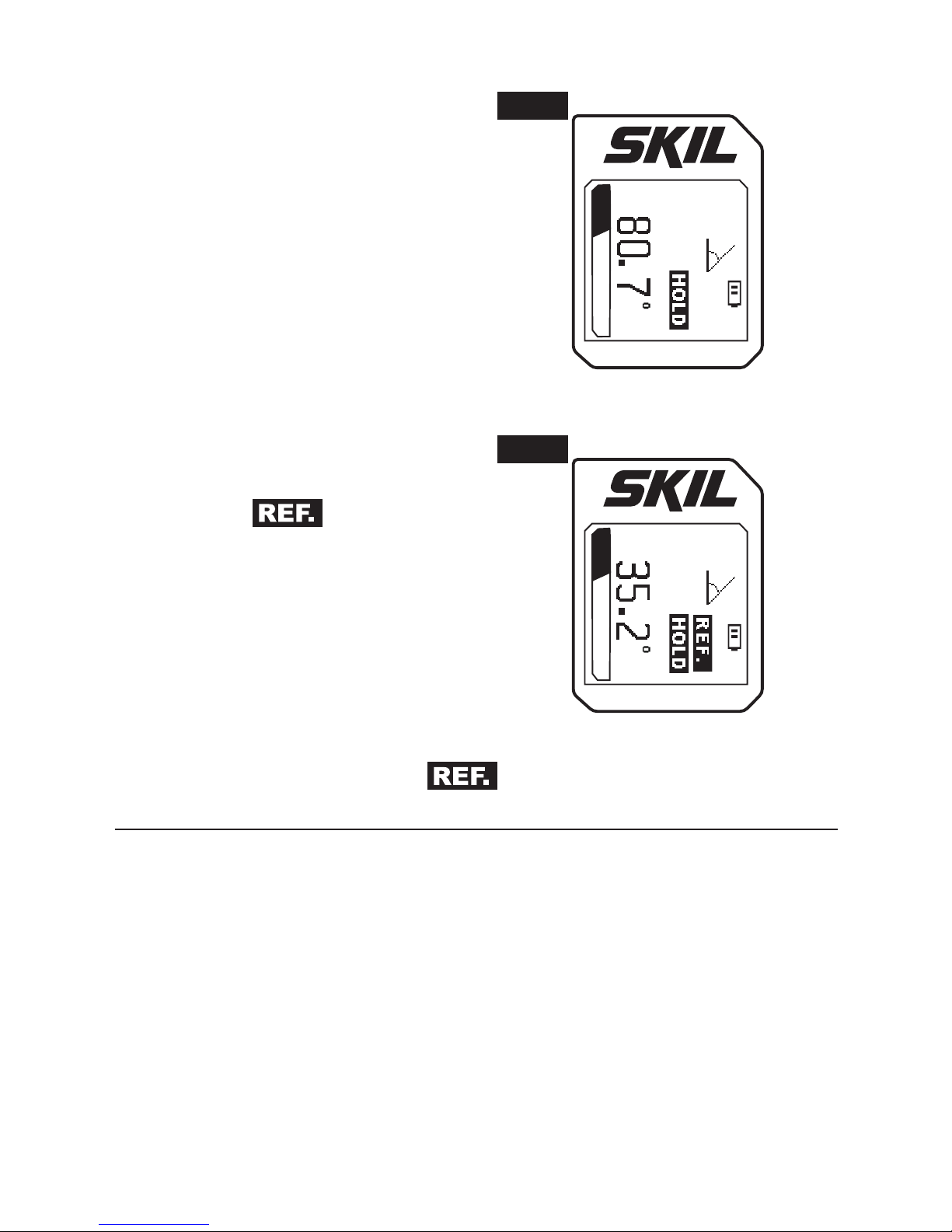
Hold
To hold and display the
measurement in the digital leveling
mode, press the Main Button
when the required measurement
is displayed: the LCD screen will
display “HOLD” (FIG. 16).
To release the hold, press the Main
Button again or press the Down
Arrow Button for 1 second.
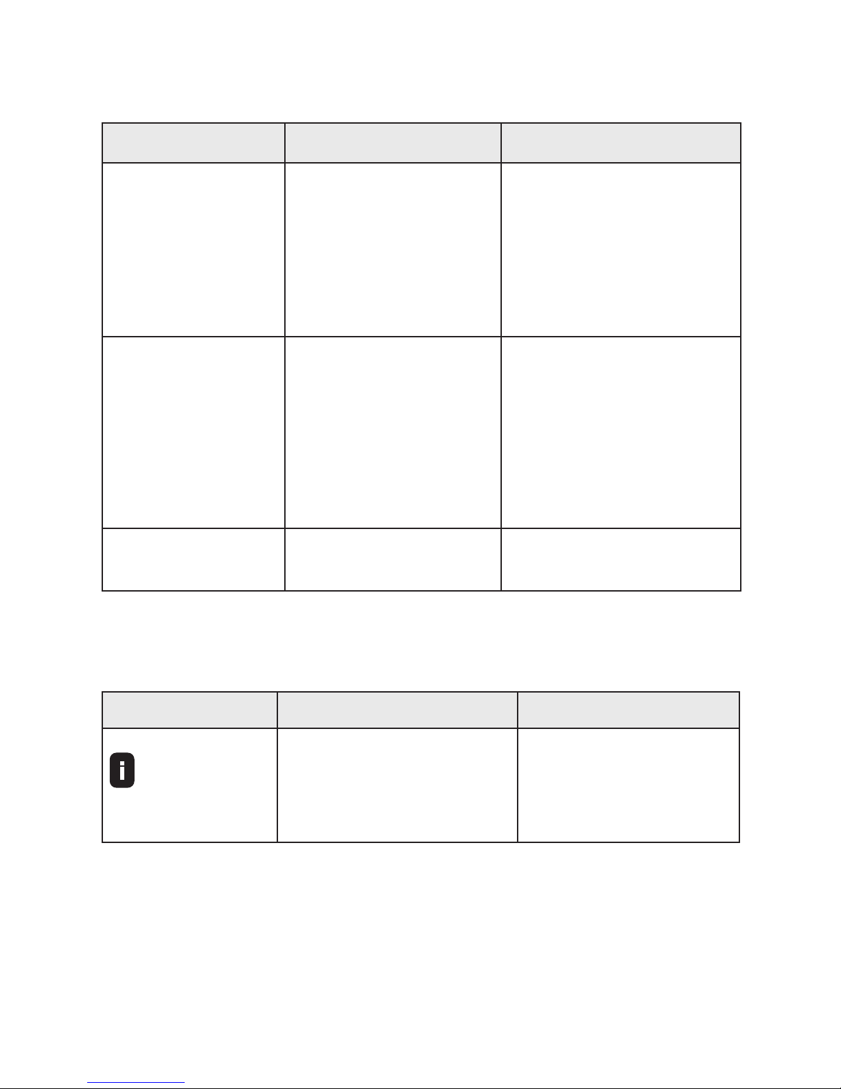
NOTE:
When entering into the
relative angle measurement mode
and the icon
is displayed,
you may press the Main Button
to hold the measurement in the
LCD display (FIG. 17). When both
the Hold and REF functions are
activated, press the Down Arrow
Button for more than 1 second;
the tool will go back to the initial
absolute angle measurement mode
without the hold and the icon
.
M O D E
Level
Fig. 16
M O D E
Level
Fig. 17

27
MAINTENANCE
This tool has been designed to be a low-maintenance tool. However,
in order to maintain its performance, you must always follow these
simple directions:
•
Avoid exposing the tool to shock, continuous vibration or extreme
hot or cold temperature.
•
Always store the tool indoors.
•
Always keep the tool free of dust and liquids. Use only a clean,
soft cloth for cleaning. Avoid using any solvents.
•
Do not disassemble the tool; this will expose the user to
hazardous radiation exposure.
•
Do not attempt to change any part of the laser lens.
•
Do not dispose of this product in re, batteries inside the product
may explode or leak.
28
TROUBLE SHOOTING
Problem Cause Remedy
Tool cannot be
switched on.
1. The battery charge
is too low.
2. The power button
did not contact
well.
1. Charge the battery.
2. Try to press the
power button
more rmly or call
customer service.
Tool can’t
measure.
The target surface
reects too intensely
(e.g. a mirror) or
insufciently (e.g.
black fabric), or the
ambient light is too
bright.
Work with a laser target
plate (not included).
Error code shows
on display.
Please refer to “Error
signals” below.
Please refer to “Error
signals” below.
The following error signals may appear on the LCD screen on your
tool:
CODE CAUSE SOLUTION
Target out of
range
Out of range.
The measuring range
for this tool is from 1 to
100 feet.
Take measurements
within the range (from
1 to 100 feet).

29
CODE CAUSE SOLUTION
Error Try
again
1. The reected laser
light is too intense.
2. The target provides
poor reection of the
laser.
3. Strong vibration.
4. The tool was moved
quickly when
measuring.
5. The tool inclines to
left or right in any
position in the indirect
measure mode.
1. Change the
measuring target.
2. Use the target plate
(not included), or
cover the target
with a piece of
white paper.
3. Always keep the
tool and target
steady.
4. Do not make
sudden movements
while measuring.
5. Always keep the
tool perpendicular
in the indirect
measure mode.
Temperature
too high
The temperature is too
high.
Wait until the
measuring tool has
reached the operating
temperature (+14 °F
to 122 °F).
Temperature
too low
The temperature is too
low.
Wait until the
measuring tool has
reached the operating
temperature (+14 °F
to 122 °F).
Low Battery
Low battery, a reminder
to charge the battery.
Charge the battery.

30
For Recycling
To preserve natural resources, please recycle or
dispose of batteries properly. This product contains
lithium-ion batteries. Local, state, or federal laws
may prohibit disposal of lithium-ion batteries in
ordinary trash. Consult your local waste authority
for information regarding available recycling and/
or disposal options.
 Loading...