

Page 1
Operating/Safety Instructions
Consignes de fonctionnement/sécurité
Instrucciones de funcionamiento
y seguridad
IMPORTANT: IMPORTANT : IMPORTANTE:
Read Before Using Lire avant usage Leer antes de usar
Consumer Information
Renseignement des consommateurs
Información para el consumidor
Toll Free Number: Appel gratuit : Número de teléfono gratuito:
1-877-SKIL999 (1-877-754-5999) http://www.skil.com
For English Parlez-vous français? ¿Habla español?
See page 2 Voir page 12 Ver página 22
1823
SM 2610995785 3/03 3/3/03 3:28 PM Page 1
Page 2

Work Area
Keep your work area clean and well lit.
Cluttered benches and dark areas invite
accidents.
Do not operate power tools in explosive
atmospheres, such as in the presence of
flammable liquids, gases, or dust. Power
tools create sparks which may ignite the dust
or fumes.
Keep by-standers, children, and visitors
away while operating a power tool.
Distractions can cause you to lose control.
Electrical Safety
Double Insulated tools are equipped with a
polarized plug (one blade is wider than the
other.) This plug will fit in a polarized outlet
only one way. If the plug does not fit fully in
the outlet, reverse the plug. If it still does
not fit, contact a qualified electrician to
install a polarized outlet. Do not change the
plug in any way. Double Insulation
eliminates the need for the three wire grounded
power cord and grounded power supply
system. Before plugging in the tool, be certain
the outlet voltage supplied is within the voltage
marked on the nameplate. Do not use “AC
only” rated tools with a DC power supply.
Avoid body contact with grounded surfaces
such as pipes, radiators, ranges and
refrigerators. There is an increased risk of
electric shock if your body is grounded. If
operating the power tool in damp locations is
unavoidable, a Ground Fault Circuit Interrupter
must be used to supply the power to your
tool. Electrician’s rubber gloves and footwear
will further enhance your personal safety.
Don't expose power tools to rain or wet
conditions. Water entering a power tool will
increase the risk of electric shock.
Do not abuse the cord. Never use the cord
to carry the tools or pull the plug from an
outlet. Keep cord away from heat, oil, sharp
edges or moving parts. Replace damaged
cords immediately. Damaged cords increase
the risk of electric shock.
When operating a power tool outside, use
an outdoor extension cord marked "W-A"
or "W." These cords are rated for outdoor use
and reduce the risk of electric shock. Refer to
“Recommended sizes of Extension Cords” in
the Accessory section of this manual.
Personal Safety
Stay alert, watch what you are doing and
use common sense when operating a
power tool. Do not use tool while tired or
under the influence of drugs, alcohol, or
medication. A moment of inattention while
operating power tools may result in serious
personal injury.
Dress properly. Do not wear loose clothing
or jewelry. Contain long hair. Keep your
hair, clothing, and gloves away from
moving parts. Loose clothes, jewelry, or long
hair can be caught in moving parts. Keep
handles dry, clean and free from oil and
grease.
Avoid accidental starting. Be sure switch is
“OFF” before plugging in. Carrying tools with
your finger on the switch or plugging in tools
that have the switch “ON” invites accidents.
Remove adjusting keys or wrenches before
turning the tool “ON”. A wrench or a key that
is left attached to a rotating part of the tool
may result in personal injury.
Do not overreach. Keep proper footing and
balance at all times. Proper footing and
balance enables better control of the tool in
unexpected situations.
Use safety equipment. Always wear eye
protection. Dust mask, non-skid safety
shoes, hard hat, or hearing protection must be
used for appropriate conditions.
Tool Use and Care
Use clamps or other practical way to
secure and support the workpiece to a
stable platform. Holding the work by hand or
against your body is unstable and may lead to
loss of control.
Read and understand all instructions. Failure to follow all instructions
listed below, may result in electric shock, fire and/or serious personal injury.
SAVE THESE INSTRUCTIONS
-2-
!
WARNING
Power Tool Safety Rules
SM 2610995785 3/03 3/3/03 3:28 PM Page 2
Page 3

-3-
Safety Rules for Routers
Do not force tool. Use the correct tool for
your application. The correct tool will do the
job better and safer at the rate for which it is
designed.
Do not use tool if switch does not turn it
“ON” or “OFF”. Any tool that cannot be
controlled with the switch is dangerous and
must be repaired.
Disconnect the plug from the power source
before making any adjustments, changing
accessories, or storing the tool. Such
preventive safety measures reduce the risk of
starting the tool accidentally.
Store idle tools out of reach of children and
other untrained persons. Tools are
dangerous in the hands of untrained users.
Maintain tools with care. Keep cutting tools
sharp and clean. Properly maintained tools,
with sharp cutting edges are less likely to bind
and are easier to control. Any alteration or
modification is a misuse and may result in a
dangerous condition.
Check for misalignment or binding of
moving parts, breakage of parts, and any
other condition that may affect the tools
operation. If damaged, have the tool
serviced before using. Many accidents are
caused by poorly maintained tools. Develop a
periodic maintenance schedule for your tool.
Use only accessories that are
recommended by the manufacturer for
your model. Accessories that may be suitable
for one tool, may become hazardous when
used on another tool.
Service
Tool service must be performed only by
qualified repair personnel. Service or
maintenance performed by unqualified
personnel could result in a risk of injury. For
example: internal wires may be misplaced or
pinched, safety guard return springs may be
improperly mounted.
When servicing a tool, use only identical
replacement parts. Follow instructions in
the Maintenance section of this manual.
Use of unauthorized parts or failure to follow
Maintenance Instructions may create a risk of
electric shock or injury. Certain cleaning
agents such as gasoline, carbon tetrachloride,
ammonia, etc. may damage plastic parts.
Hold tool by insulated gripping surfaces
when performing an operation where the
cutting tool may contact hidden wiring or
its own cord. Contact with a "live" wire will
make exposed metal parts of the tool "live"
and shock the operator. If cutting into
existing walls or other blind areas where
electrical wiring may exist is unavoidable,
disconnect all fuses or circuit breakers
feeding this worksite.
Always make sure the work surface is
free from nails and other foreign objects.
Cutting into a nail can cause the bit and the
tool to jump and damage the bit.
Never hold the workpiece in one hand
and the tool in the other hand when in
use. Never place hands near or below
cutting surface. Clamping the material and
guiding the tool with both hands is safer.
Never lay workpiece on top of hard
surfaces, like concrete, stone, etc...
Protruding cutting bit may cause tool to
jump.
Always wear safety goggles and dust
mask. Use only in well ventilated area.
Using personal safety devices and working
in safe environment reduces risk of injury.
After changing the bits or making any
adjustments, make sure the collet nut and
any other adjustment devices are
securely tightened. Loose adjustment
device can unexpectedly shift, causing loss
of control, loose rotating components will be
violently thrown.
Never start the tool when the bit is
engaged in the material. The bit cutting
edge may grab the material causing loss of
control of the cutter.
Always hold the tool with two hands
during start-up. The reaction torque of the
motor can cause the tool to twist.
When routing or cutting, the direction of
feed with the bit’s cutting edge into the
material is very important. Always feed
the bit into the material in the same
SM 2610995785 3/03 3/3/03 3:28 PM Page 3
Page 4

direction as the cutting edge is exiting
from the material (which is the same
direction as the chips are thrown). NOTE:
inside and outside cuts will
require different
feed direction, refer to section on feeding the
router. Feeding the tool in the wrong direction,
causes the cutting edge of the bit to climb out
of the work and pull the tool in the direction of
this feed.
Never use dull or damaged bits. Sharp
bits must be handled with care. Damaged
bits can snap during use. Dull bits require
more force to push the tool, possibly
causing the bit to break.
Never touch the bit during or immediately
after the use. After use the bit is too hot to
be touched by bare hands.
Never lay the tool down until the motor
has come to a complete standstill. The
spinning bit can grab the surface and pull
the tool out of your control.
Never use bits that have a cutting
diameter greater than the opening in the
base.
Some dust created by
power sanding, sawing,
grinding, drilling, and other construction
activities contains chemicals known to
cause cancer, birth defects or other
reproductive harm. Some examples of
these chemicals are:
• Lead from lead-based paints,
• Crystalline silica from bricks and cement
and other masonry products, and
• Arsenic and chromium from chemically-
treated lumber.
Your risk from these exposures varies,
depending on how often you do this type of
work. To reduce your exposure to these
chemicals: work in a well ventilated area,
and work with approved safety equipment,
such as those dust masks that are specially
designed to filter out microscopic particles.
-4-
!
WARNING
SM 2610995785 3/03 3/3/03 3:28 PM Page 4
Page 5
-5-
IMPORTANT: Some of the following symbols may be used on your tool. Please study them
and learn their meaning. Proper interpretation of these symbols will allow you to operate the
tool better and safer.
Symbol Name Designation/Explanation
V Volts Voltage (potential)
A Amperes Current
Hz Hertz Frequency (cycles per second)
W Watt Power
kg Kilograms Weight
min Minutes Time
s Seconds Time
Diameter Size of drill bits, grinding wheels, etc.
n
0
No load speed Rotational speed, at no load
.../min Revolutions or reciprocation per minute Revolutions, strokes, surface speed,
orbits etc. per minute
0 Off position Zero speed, zero torque...
1, 2, 3, ... Selector settings Speed, torque or position settings.
I, II, III, Higher number means greater speed
Infinitely variable selector with off Speed is increasing from 0 setting
Arrow Action in the direction of arrow
Alternating current Type or a characteristic of current
Direct current Type or a characteristic of current
Alternating or direct current Type or a characteristic of current
Class II construction Designates Double Insulated
Construction tools.
Earthing terminal Grounding terminal
Warning symbol Alerts user to warning messages
Ni-Cad RBRC seal Designates Ni-Cad battery recycling
program
Symbols
0
This symbol designates
that this tool is listed by
Underwriters Laboratories.
This symbol designates
that this tool is listed by
the Canadian Standards
Association.
This symbol designates
that this tool is listed to
Canadian Standards by
Underwriters Laboratories.
This symbol
designates
that
this tool
complies
to NOM
Mexican
Standards.
This symbol designates
that this tool is listed by
Underwriters Laboratories,
and listed to Canadian
Standards by Underwriters
Laboratories.
SM 2610995785 3/03 3/3/03 3:28 PM Page 5
Page 6
-6-
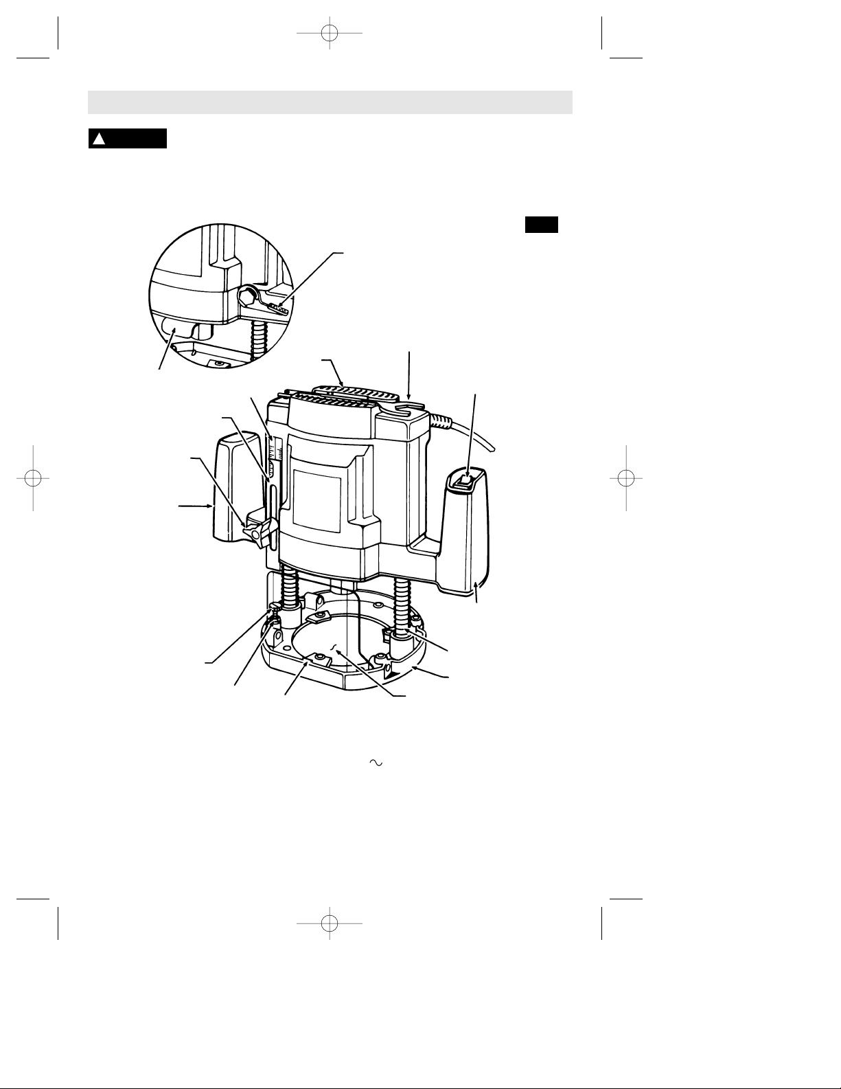
Functional Description and Specifications
Disconnect the plug from the power source before making any
assembly, adjustments or changing accessories. Such preventive safety
measures reduce the risk of starting the tool accidentally.
!
WARNING
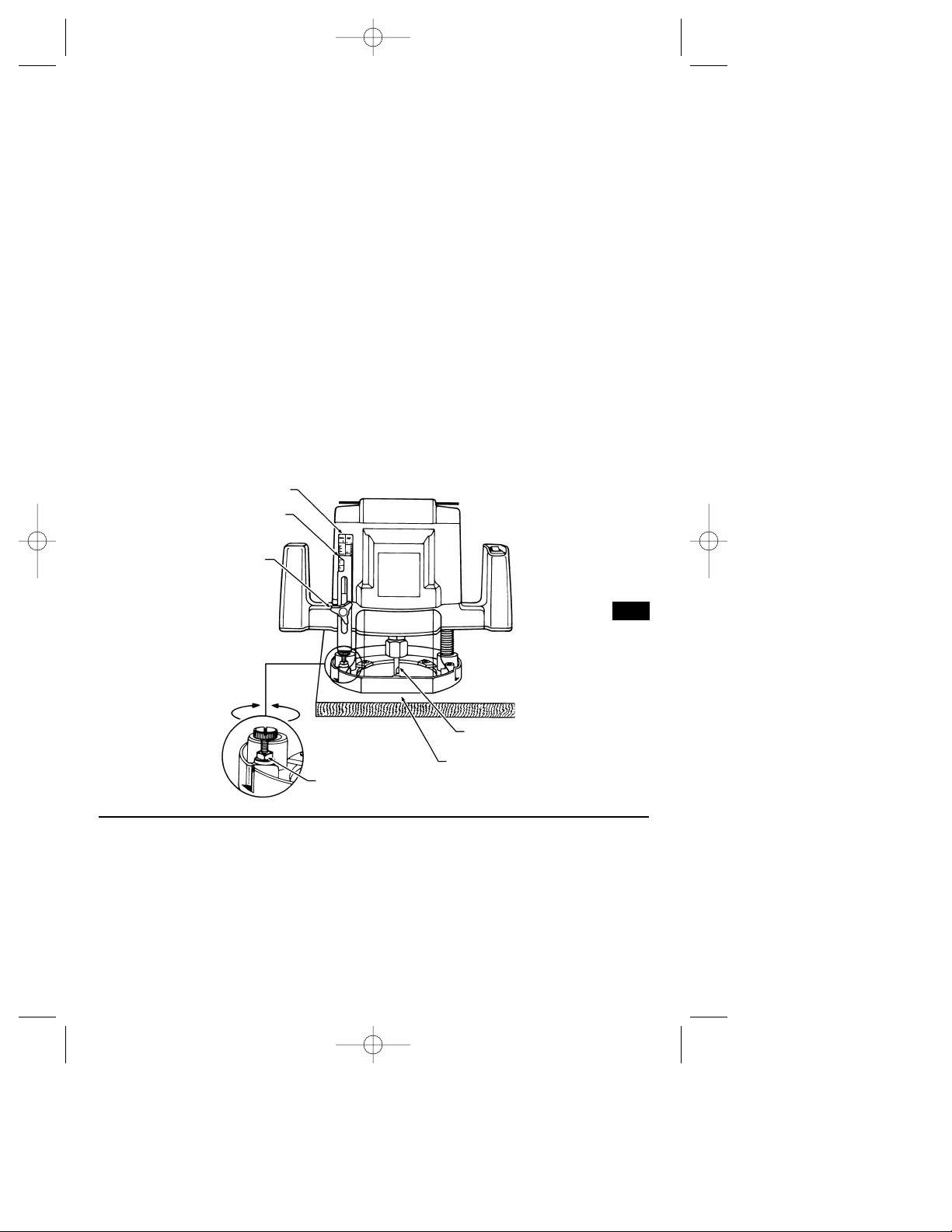
Routers
LOCK
LEVER
COLLET LOCK
WRENCH & STORAGE AREA
ON/OFF
SWITCH
BASE
CHIP DEFLECTOR
TAB
NUT
PLUNGER SPRINGS
FINE DEPTH
ADJUSTMENT
LEFT
HANDLE
RIGHT
HANDLE
KNOB
DEPTH
GAUGE
DEPTH
SCALE
FIG. 1
VENTS
Model number 1823
Voltage rating 120 V 50 - 60Hz
Amperage rating 8.5 A
No load speed n
0
25,000/min
Collet capacities 1/4"
VIEW OF OPPOSITE SIDE OF ROUTER
SM 2610995785 3/03 3/3/03 3:28 PM Page 6
Page 7
Operating Instructions
-7-
Assembly
SELECTING BITS
A wide assortment of router bits with different
profiles are available as accessories.
To prevent personal injury.
Always remove the plug from
power source before removing or installing
bits or accessories.
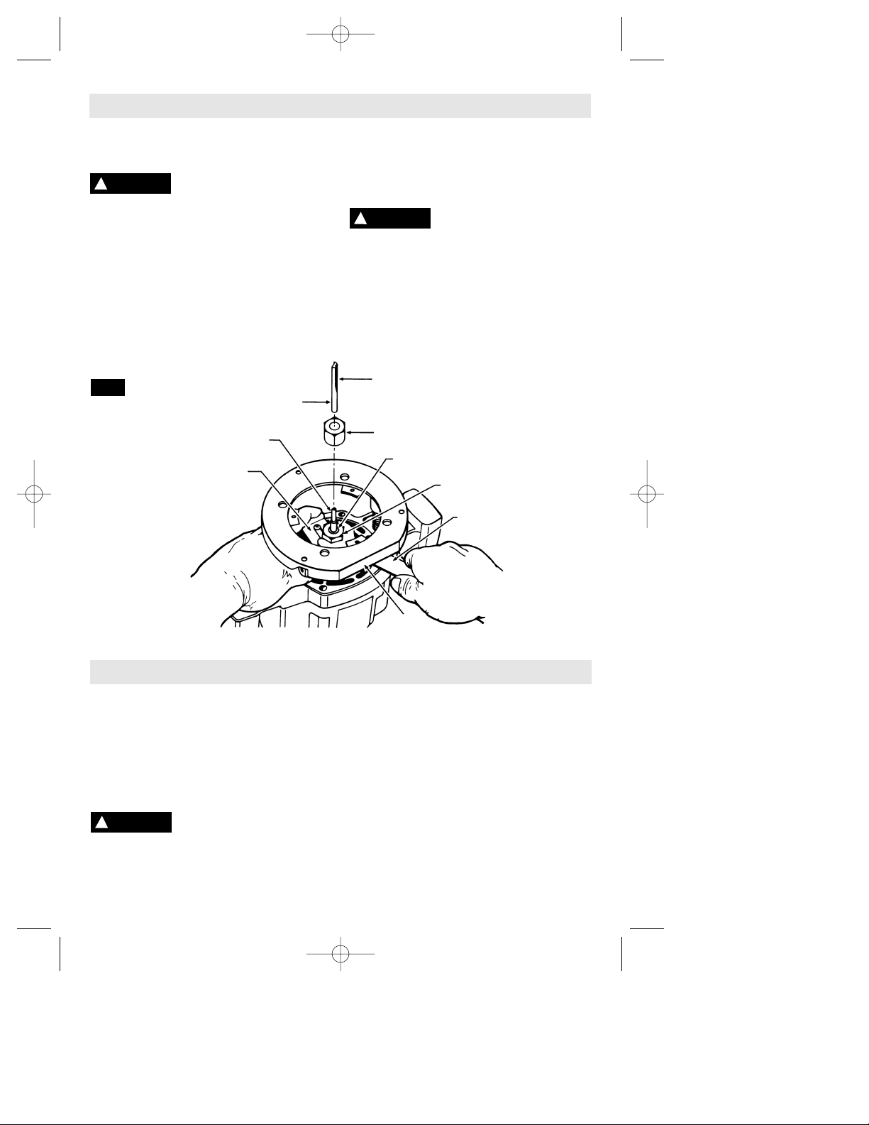
INSTALLING AND REMOVING BITS
1. Place router upside down as shown in (Fig.
2), or lay router on its side with the flat side of
base resting on the bench.
2. Press collet lock to stop rotation of collet
nut. NOTE: it may be necessary to rotate
collet nut to engage collet lock.
3. With the wrench provided, turn collet nut
counterclockwise to loosen.
4. Insert bit three fourths into the collet, and
securely tighten collet nut clockwise with the
wrench provided.
To prevent damage to tool,
do not tighten collet nut
without a bit.
REMOVING BITS
Repeat steps 1, 2 and 3 of above and remove
bit.
ATTENTION: Be sure that the diameter of the
bit shank is the same size as the inside
diameter of the collet — your router is
equipped with a 1/4" collet.
!
WARNING
CHIP DEFLECTOR
The chip deflector helps keep dust and chips
out of your face. To remove, press inward on
center of deflector until it releases from tab in
base and lift out. To attach, place deflector
into position as shown in (Fig. 1). Then flex
sides of deflector while pushing down until
tab on base snaps into slot on deflector.
Safety glasses must always
be worn.
Skil plunge routers are designed for speed,
accuracy and convenience in performing
cabinet work, routing, fluting, beading, covecutting, dove tails, etc. It will enable you to
accomplish inlay work, decorative edges and
many types of special carving.
PLUNGING ACTION
The plunge feature simplifies depth
adjustments and will allow the cutting bit to
easily and accurately enter the workpiece. To
lower, loosen lock lever (Fig. 1), and apply
downward pressure until depth gauge makes
contact with the fine depth adjustment screw,
and tighten lock lever. Loosen lever and
WRENCH
COLLET
COLLET NUT
BIT
SHANK
BIT
COLLET
LOCK
BASE
FIG. 2
!
CAUTION
!
WARNING
COLLET NUT
SM 2610995785 3/03 3/3/03 3:28 PM Page 7
Page 8
release pressure and the router will
automatically retract the bit from the
workpiece. It is advisable to retract the bit
whenever it is not engaged in workpiece.
WRENCH AND STORAGE AREA
Your router is equipped with a double-ended
wrench. The large end is for removing or
installing bits. The small end is for securing
the nut on the fine depth adjustment screw.
Your router also has a convenient storage
area located on top of your tool where your
wrench may be stored by simply sliding it into
place as shown in (Fig. 1).
DEPTH GAUGE
Your router is equipped with a depth gauge
and a depth scale calibrated in inches and
millimeters. It also features a fine depth
adjustment screw that allows the depth
gauge to stop the router at desired depths of
cut.
TO ADJUST DEPTH
1. Loosen knob so that the depth gauge
moves freely.
2. Loosen lock lever and push down on router
until the bit touches the work surface and the
depth gauge is resting on top of the fine
depth adjustment screw as shown in (Fig. 3),
and tighten lock lever.
3. Raise depth gauge desired amount on
scale and tighten knob. For example, if you
raise the depth gauge up 1/8" on scale you
will get a 1/8" depth of cut.
4. Loosen lock lever and lower router until
depth gauge stops on top of the fine depth
adjustment screw. Make a few practice cuts
on a piece of scrap wood to check if depth of
cut is correct. If depth of cut needs to be
changed slightly, loosen nut on fine depth
adjustment screw with the wrench provided
and rotate screw until you reach desired
depth. Half turn of the fine depth adjustment
screw equals 1/64 of an inch. Full turn equals
1/32".
5. After depth of cut is obtained securely
tighten nut on fine depth adjustment screw
with the wrench provided to maintain adjustment.
-8-
WORK SURFACE
BIT
FINE DEPTH
ADJUSTMENT HALF
TURN = 1/64"
NUT
Clockwise
To Lower
Counter-
clockwise
To Raise
SCALE
KNOB
DEPTH GAUGE
FIG. 3
ON/OFF SWITCH
Your router is equipped with an ON/OFF
switch located in the right handle. The switch
also has a red “ON” indicator that alerts user
that the router is on before plugging in tool.
To turn router on, press switch to ON. To turn
router off, press switch to OFF.
Always hold the router off the work when
turning the switch on or off. Contact the work
with the router after the router has reached full
speed, and remove it from the work before
turning the switch off. Operating in this manner
will prolong switch and motor life and will
greatly increase the quality of your work
(Fig. 1).
SM 2610995785 3/03 3/3/03 3:28 PM Page 8
Page 9
-9-
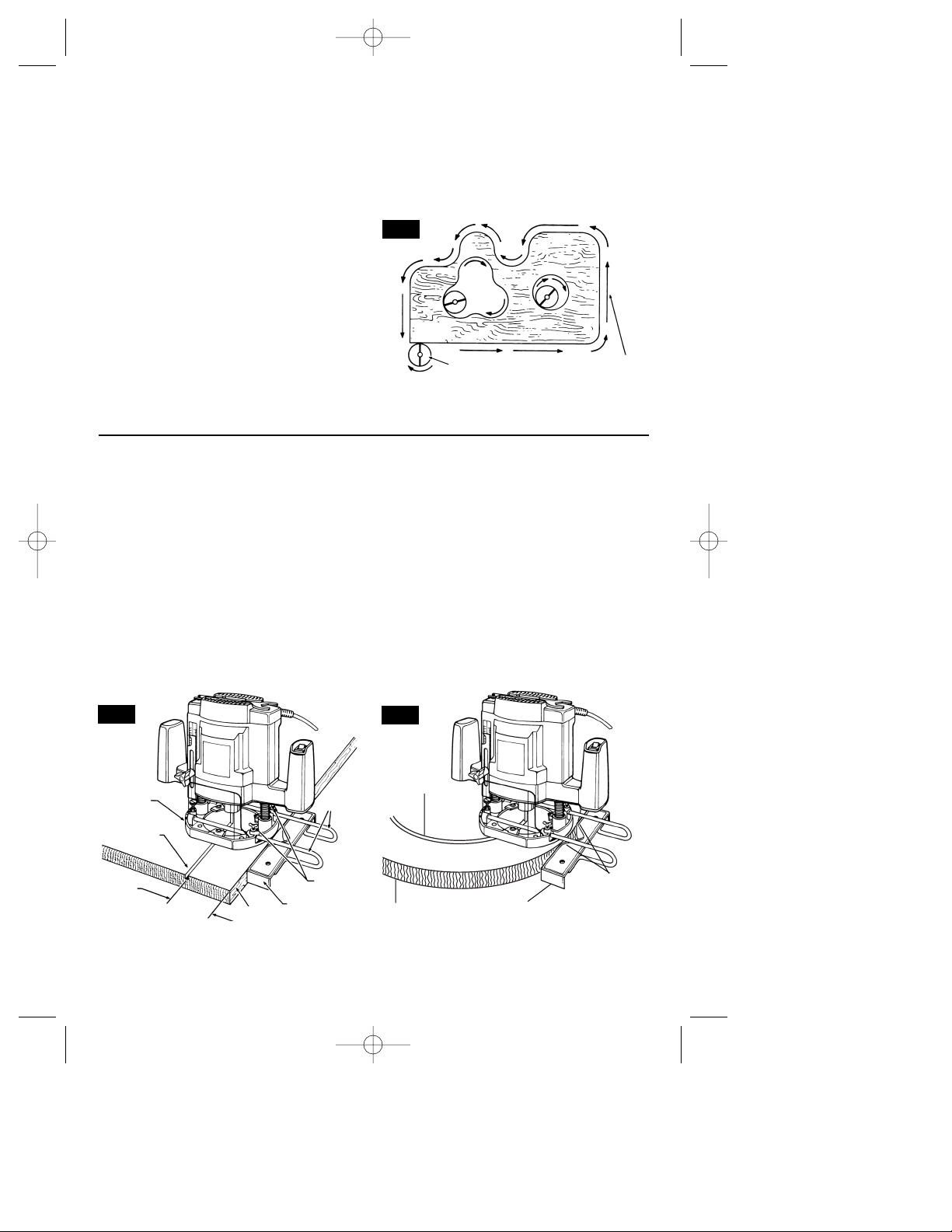
FEEDING THE ROUTER
As seen from the top of the router, the bit
turns clockwise and the cutting edges face
accordingly. Therefore, the most efficient cut
is made by feeding the router so that the bit
turns into the work, not away. Figure 4 shows
proper feed for various cuts. How fast you
feed depends on the hardness of the wood
and the size of the cut. For some materials,
several cuts of increasing depth are required.
As a general rule, it is best to pull the router
— not push. You get greater visibility, cleaner
cut, more control and less flying sawdust.
If the router is hard to control, heats up, runs
very slowly or leaves an imperfect cut,
consider these causes:
1. Wrong direction of feed — hard to control.
2. Feeding too fast — overloads motor.
3. Dull bit -— overloads motor.
4. Cut is too large for one pass — overloads
motor.
5. Feeding too slow — leaves friction burns
on work.
Feed smoothly and steadily (do not force).
You will soon learn how the router sounds
and feels when it is working best.
FIG. 4
CUTTER
WORK
DIRECTION
OF ROUTER
FEED
GUIDING ROUTER
The router can be guided through the work in
any of several ways. The method you use
depends, of course, on the demands of the
particular job and on convenience.
STRAIGHT AND CIRCULAR EDGE GUIDE
(Not included, available as accessory)
Use this handy accessory for ease and
accuracy in making curved and straight cuts.
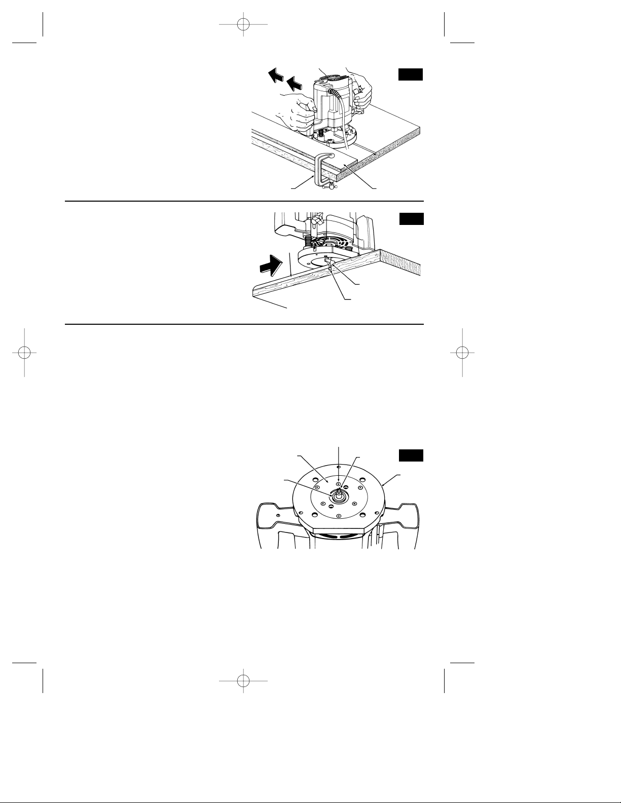
ATTACHING GUIDE
Insert edge guide rods through holes in base,
slide edge guide to desired width as shown in
(Fig. 5), and secure in place with the two wing
screws provided.
One method of locating the guide is to mark
the center of groove to be cut, set the router
flat on the work with the bit just touching and
aligned over the center of groove. Bring the
guide to the edge of the work, and securely
tighten screws. Whenever in doubt about
dimensions, make a trial cut on scrap
material. For guiding along a circular edge,
the notch in the center of the edge guide will
contact the material at the two points shown
(Fig. 6).
FIG. 5
FIG. 6
DESIRED
WIDTH
CUT
BASE
EDGE GUIDE
WORK
WING
SCREWS
EDGE
GUIDE
RODS
CUT
WORK
EDGE GUIDE
POINTS OF
CONTACT
SM 2610995785 3/03 3/3/03 3:28 PM Page 9
Page 10
-10-
TEMPLATES
Using a template lets you duplicate designs or
letters uniformly time after time. This technique
requires the use of an accessory adapter plate
and a guide bushing.
ADAPTER PLATE
(Not included, available as accessory)
Attach the accessory adapter guide to the
router base with the three screws provided as
shown in (Fig. 9), and you can use a variety of
Skil guide bushings available. The accessory
adapter plate also has auxiliary holes which will
allow you to attach other guide bushings made
by Craftsman, Milwaukee, Porter Cable,
Rockwell and Black & Decker.
GUIDE BUSHINGS
(Not included, available as accessory)
The guide bushing shown in (Fig. 9), is
essentially a plate with a collar which is
inserted through the hole in accessory adapter
plate from below and fastened with screws
from above. The guide rides along the edge of
the template while the router bit, protruding
below, cuts into the work.
Be sure the thickness of the template is the
same or larger than the guide surface of the
collar.
Do not use a bit that may touch the inside of
the collar. Select a bit that is about 1/16" less
in diameter.
After attaching any guide bushing, always turn
the router upside down and lower base to
check if the bit is protruding through the center
of the collar. If adjustment is necessary loosen
the three screws that secure the adapter plate
to the base and move adapter plate until bit is
in the center of collar (Fig. 9).
FREEHAND ROUTING
Many effects are gained by using the router
freehand with a small diameter bit. Usually the
craftsman pencils the outline or script he
desires onto the work and uses the pencil line
as a guide.
BOARD GUIDES
Clamp a straight or curved board onto the
work to form a guide as shown in (Fig. 7). This
is particularly handy for panels or any large
surface area.
FIG. 7
SECURELY CLAMP
BOARD GUIDE
BOARD
GUIDE
PILOT TIPPED AND BEARING GUIDE BITS
The lower portion of a pilot tipped bit, as
shown in (Fig. 8), is a shaft with no cutting
edges. Bearing guide bits have a ball bearing
to pilot the bit.
This pilot slides along the edge of the work as
the rotating blades make the cut, forming
molding or decorative edges. The edge on
which the pilot slides should be perfectly
smooth since any irregularities are transferred
to the shaped surface.
PILOT SLIDES ALONG
EDGE OF WORK
CUTTER PART OF
PILOT TIPPED BIT
CUT
FIG. 8
BASE
BIT
ADAPTER PLATEALIGNMENT SCREWS
ADAPTER
PLATE
GUIDE
BUSHING
FIG. 9
SM 2610995785 3/03 3/3/03 3:28 PM Page 10
Page 11

-11-
Accessories
Service
Preventive maintenance
performed by unauthorized
personnel may result in misplacing of
internal wires and components which
could cause serious hazard. We
recommend that all tool service be performed
by a Skil Factory Service Center or Authorized Skil Service Station.
TOOL LUBRICATION
Your Skil tool has been properly lubricated
and is ready to use. It is recommended that
tools with gears be regreased with a special
gear lubricant at every brush change.
CARBON BRUSHES
The brushes and commutator in your tool
have been engineered for many hours of
dependable service. To maintain peak
efficiency of the motor, we recommend every
two to six months the brushes be examined.
Only genuine Skil replacement brushes
specially designed for your tool should be
used.
BEARINGS
After about 300-400 hours of operation, or at
every second brush change, the bearings
should be replaced at Skil Factory Service
Center or Authorized Skil Service Station.
Bearings which become noisy (due to heavy
load or very abrasive material cutting) should
be replaced at once to avoid overheating or
motor failure.
Cleaning
To avoid accidents always
disconnect the tool from
the power supply before cleaning or
performing any maintenance. The tool may
be cleaned most effectively with compressed
dry air. Always wear safety goggles when
cleaning tools with compressed air.
Ventilation openings and switch levers must
be kept clean and free of foreign matter. Do
not attempt to clean by inserting pointed
objects through openings.
Certain cleaning agents
and solvents damage
plastic parts. Some of these are: gasoline,
carbon tetrachloride, chlorinated cleaning
solvents, ammonia and household detergents
that contain ammonia.
!
WARNING
!
WARNING
Maintenance
!
CAUTION
If an extension cord is
necessary, a cord with
adequate size conductors that is capable
of carrying the current necessary for your
tool must be used. This will prevent
excessive voltage drop, loss of power or
overheating. Grounded tools must use 3wire extension cords that have 3-prong
plugs and receptacles.
NOTE: The smaller the gauge number, the
heavier the cord.
RECOMMENDED SIZES OF EXTENSION CORDS
120 VOLT ALTERNATING CURRENT TOOLS
!
WARNING
Tool’s
Ampere
Rating
Cord Size in A.W.G.
Wire Sizes in mm
2
3-6
6-8
8-10
10-12
12-16
18 16 16 14 .75 .75 1.5 2.5
18 16 14 12 .75 1.0 2.5 4.0
18 16 14 12 .75 1.0 2.5 4.0
16 16 14 12 1.0 2.5 4.0 —
14 12 — — — — — —
25 50 100 150 15 30 60 120
Cord Length in Feet Cord Length in Meters
(*= standard equipment)
(**= optional accessories)
BITS
For fast smooth cutting, keep bits sharp. A dull
bit slows cutting speed, makes rougher cuts,
discolors or burns the work through excessive
heat and overloads the motor.
ROUTER DUST COLLECTION
(Not included, available as accessory)
If you have a shop vacuum system you may
want to purchase the Skil 91812 Dust
Collection Hood for improved accuracy and
utility, particularly in freehand routing.
SM 2610995785 3/03 3/3/03 3:28 PM Page 11
Page 12

-12-
Vous devez lire et comprendre toutes les instructions. Le non-respect, même partiel,
des instructions ci-après entraîne un risque de choc életrique, d'incendie et/ou de
blessures graves.
CONSERVEZ CES INSTRUCTIONS
AVERTISSEMENT
!
Aire de travail
Veillez à ce que l'aire de travail soit propre et bien
éclairée. Le désordre et le manque de lumière favorisent
les accidents.
N'utilisez pas d'outils électriques dans une
atmosphère explosive, par exemple enprésence de
liquides, de gaz ou de poussières inflammables. Les
outils électriques créent des étincelles qui pourraient
enflammer les poussières ou les vapeurs.
Tenez à distance les curieux, les enfants et les
visiteurs pendant que vous travaillezavec un outil
électrique. Ils pourraient vous distraire et vous faire
faire une fausse manoeuvre.
Sécurité électrique
Les outils à double isolation sont équipés d'une fiche
polarisée (une des lames est pluslarge que l'autre),
qui ne peut se brancher que d'une seule façon dans
une prise polarisée. Si la fiche n'entre pas
parfaitement dans la prise, inversez sa position ; si
elle n'entre toujours pasbien, demandez à un
électricien qualifié d'installer une prise de courant
polarisée. Ne modifiez pas la fiche de l'outil. La
double isolation élimine le besoin d'un cordon
d'alimentationà trois fils avec mise à la terre ainsi que
d'une prise de courant mise à la terre. Avant de brancher
l'outil, assurez-vous que la tension de la prise
correspond, à celle indiquée sur la plaque signalétique.
N'utilisez pas d'outils prévus pour courant alternatif
seulement avec une source de courant continu.
Évitez tout contact corporel avec des surfaces mises à
la terre (tuyauterie, radiateurs, cuisinières,
réfrigérateurs, etc.). Le risque de choc électrique est
plus grand si votre corps est encontact avec la terre.Si
l'utilisation de l'outil électrique dans un endroit humide
est inévitable, un disjoncteur de fuite à la terre doit être
utilisé pour alimenter votre outil. Des chaussures et des
gants en caoutchouc d'électricien contribueront à
accroître davantage votre sécurité personnelle.
N'exposez pas les outils électriques à la pluie ou à
l'eau. La présence d'eau dans un outil électrique
augmente le risque de choc électrique.
Ne maltraitez pas le cordon. Ne transportez pas l'outil
par son cordon et ne débranchez pas la fiche en tirant
sur le cordon. N'exposez pas le cordon à la chaleur, à
des huiles, à des arêtes vives ou à des pièces en
mouvement. Remplacez immédiatement un cordon
endommagé. Un cordon endommagé augmente le
risque de choc électrique.
Lorsque vous utilisez un outil électrique à l'extérieur,
employez un prolongateur pour l'extérieur marqué «
W-A » ou « W ». Ces cordons sont faits pour être utilisés
à l'extérieur et réduisent le risque de choc électrique.
Reportez-vous aux « Dimensions recommandées des
cordons de rallonge » dans la section Accessoires de ce
manuel.
Sécurité des personnes
Restez alerte, concentrez-vous sur votre travail et
faites preuve de jugement. N'utilisez pas un outil
électrique si vous êtes fatigué ou sous l'influence de
drogues, d'alcool ou de médicaments. Un instant
d'inattention suffit pour entraîner des blessures graves.
Habillez-vous convenablement. Ne portez ni
vêtements flottants ni bijoux. Confinez les cheveux
longs. N'approchez jamais les cheveux, les vêtements
ou les gants des pièces en mouvement. Des vêtements
flottants, des bijoux ou des cheveux longs risquent
d'être happés par des pièces en mouvement. Gardez les
poignées sèches, propres et exemptes d'huile et de
graisse.
Méfiez-vous d'un démarrage accidentel. Avant de
brancher l'outil, assurez-vous que son interrupteur est
sur ARRÈT. Le fait de transporter un outil avec le doigt
sur la détente ou de brancher un outil dont l'interrupteur
est en position MARCHE peut mener tout droit à un
accident.
Enlevez les clés de réglage ou de serrage avant de
démarrer l'outil. Une clé laissée dans une pièce
tournante de l'outil peut provoquer des blessures.
Ne vous penchez pas trop en avant. Maintenez un bon
appui et restez en équilibre entout temps. Un bonne
stabilité vous permet de mieux réagir à une situation
inattendue.
Utilisez des accessoires de sécurité. Portez toujours
des lunettes ou une visière. Selon les conditions, portez
aussi un masque antipoussière, des bottes de sécurité
antidérapantes, un casque protecteur et/ou un appareil
antibruit.
Utilisation et entretien des outils
Immobilisez le matériau sur une surface stable au
moyen de brides ou de toute autre façon adéquate. Le
fait de tenir la pièce avec la main ou contre votre corps
Règles de Sécurité Générales
SM 2610995785 3/03 3/3/03 3:28 PM Page 12
Page 13

-13-
offre une stabilité insuffisante et peut amener un
dérapage de l'outil.
Ne forcez pas l'outil. Utilisez l'outil approprié à la
tâche. L'outil correct fonctionne mieux et de façon plus
sécuritaire. Respectez aussi la vitesse de travail qui lui
est propre.
N'utilisez pas un outil si son interrupteur est bloqué.
Un outil que vous ne pouvez pas commander par son
interrupteur est dangereux et doit être réparé.
Débranchez la fiche de l'outil avant d'effectuer un
réglage, de changer d'accessoire oude ranger l'outil.
De telles mesures préventives de sécurité réduisent le
risque de démarrage accidentel de l'outil.
Rangez les outils hors de la portée des enfants et
d'autres personnes inexpérimentées. Les outils sont
dangereux dans les mains d'utilisateurs novices.
Prenez soin de bien entretenir les outils. Les outils de
coupe doivent être toujours bien affûtés et propres.
Des outils bien entretenus, dont les arêtes sont bien
tranchantes, sont moins susceptibles de coincer et plus
faciles à diriger.Toute altération ou modification
constitue un usage erroné et peut causer un danger.
Soyez attentif à tout désalignement ou coincement des
pièces en mouvement, à tout bris ou à toute autre
condition préjudiciable au bon fonctionnement de
l'outil. Si vous constatez qu'un outil est endommagé,
faites-le réparer avant de vous en servir. De nombreux
accidents sont causés par des outils en mauvais état.
Élaborez un calendrier d'entretien périodique de votre
outil.
N'utilisez que des accessoires que le fabricant
recommande pour votre modèle d'outil. Certains
accessoires peuvent convenir à un outil, mais être
dangereux avec un autre.
Réparation
La réparation des outils électriques doit être confiée à
un réparateur qualifié. L'entretien ou la réparation d'un
outil électrique par un amateur peut avoir des
conséquences graves. Ainsi, des fils internes peuvent
être mal placés ou pincés, des ressorts de rappel de
protecteur peuvent être montés erronément.
Pour la réparation d'un outil, n'employez que des
pièces de rechange d'origine. Suivez les directives
données à la section « Réparation » de ce manuel.
L'emploi de pièces non autorisées ou le non-respect des
instructions d'entretien peut créer un risque de choc
électrique ou de blessures. Certains agents nettoyants
tels qu'essence, tétrachlorure de carbone, ammoniac,
etc., peuvent abîmer les pièces en plastique.
Tenez l'outil par les surfaces isolées de prise en
exécutant une opération lorsque l'outil de coupe peut
venir en contact avec des fils cachés ou son propre
cordon. Le contact avec un fil sous tension rendra les
parties métalliques exposées de l'outil sous tension et
causera des secousses électriques à l'opérateur. Pour
couper dans des murs existants ou autres endroits
aveugles pouvant dissimuler des fils électriques,
débranchez tous les fusibles ou les disjoncteurs
alimentant ce lieu de travail.
Assurez-vous toujours que la surface de travail est
exempte de clous et autres objets étrangers. La coupe
dans un clou peut faire sauter la lame et l'outil, et ainsi
abîmer la lame.
Ne tenez jamais le matériau d'une main et l'outil de
l'autre lorsque vous en faites usage. Ne placez jamais
les mains sous la surface de coupe ou à proximité de
celle-ci. Il est plus sûr de cramponner le matériau et de
guider l'outil des deux mains.
Ne posez jamais le matériau sur des surfaces dures
telles que le béton, la pierre, etc. ... La lame de coupe
en saillie peut faire sauter l'outil.
Portez toujours des lunettes de sécurité et un masque
anti-poussières. N'utilisez l'outil qu'à un endroit bien
aéré. L'utilisation de dispositifs de sécurité personnelle
et le travail dans un environnement sûr réduisent les
risques de blessures.
Après avoir changé les lames ou effectué quelque
réglage que ce soit, assurez-vous que l'écrou de la
douille et tout autre dispositif de réglage sont bien
serrés. Un dispositif de réglage lâche peut bouger
soudainement et causer ainsi une perte de contrôle avec
projection violente des composants en rotation.
Ne mettez jamais l'outil en marche alors que la lame
est enfoncée dans le matériau. Le tranchant de la lame
peut se coincer dans le matériau et vous faire perdre le
contrôle du couteau. Tenez toujours le couteau des
deux mains durant la mise en marche. Le couple de
réaction du moteur peut faire tordre l'outil.
Quand on toupille ou on coupe, le sens de l’avance
par rapport au mouvement du tranchant de l’outil
dans le matériau est très important. Toujours
travailler en opposition, c’est à dire faire avancer
l’outil dans le matériau dans la direction du bord
Règles de sécurité concernant les toupies
SM 2610995785 3/03 3/3/03 3:28 PM Page 13
Page 14

tranchant lorsque celui-ci quitte le matériau (ce qui
est aussi le sens d’évacuation des copeaux).
REMARQUE : Les coupes intérieures et extérieures
nécessiteront des sens de déplacement différents référez-vous à la section consacrée au sens de
déplacement de la toupie. Si l'outil est introduit dans le
mauvais sens, le tranchant de la lame peut sortir du
matériau et tirer l'outil dans le sens de cette
introduction.
N'utilisez jamais de lames émoussées ou abîmées.
Les lames affilées doivent être maniées soigneusement.
Les mèches abîmées peuvent se rompre brusquement
durant l'usage. Les lames émoussées nécessitent plus
de force pour pousser l'outil, causant éventuellement un
bris de la lame.
Ne touchez jamais la lame durant ou immédiatement
après l'usage. Après usage, la lame est trop chaude
pour être touchée à main nue.
Ne posez jamais l'outil avant que le moteur ne se soit
arrêté complètement. La lame en rotation peut saisir la
surface et vous faire perdre le contrôle de l'outil.
N’utilisez jamais des fers dont le diamètre de coupe est
supérieur à celui de l’ouverture pratiquée dans la base.
Les travaux à la machine
tel que ponçage, sciage,
meulage, perçage et autres travaux du bâtiment
peuvent créer des poussières contenant des produits
chimiques qui sont des causes reconnues de cancer,
de malformation congénitale ou d’autres problèmes
reproductifs. Ces produits chimiques sont, par
exemple :
• Le plomb provenant des peintures à base de plomb,
• Les cristaux de silices provenant des briques et du
ciment et d’autres produits de maçonnerie, et
• L’arsenic et le chrome provenant des bois traités
chimiquement.
Le niveau de risque dû à cette exposition varie avec la
fréquence de ces types de travaux. Pour réduire
l’exposition à ces produits chimiques, il faut travailler
dans un lieu bien ventilé et porter un équipement de
sécurité approprié tel que certains masques à poussière
conçus spécialement pour filtrer les particules
microscopiques.
-14-
AVERTISSEMENT
!
SM 2610995785 3/03 3/3/03 3:28 PM Page 14
Page 15

-15-
Symboles
Important : Certains des symboles suivants peuvent être utilisés sur votre outil. Veuillez les étudier et apprendre
leur signification. Une interprétation appropriée de ces symboles vous permettra d'utiliser l'outil de façon plus
efficace et plus sûre.
Symbole Nom Désignation/Explication
V Volts Tension (potentielle)
A Ampères Courant
Hz Hertz Fréquence (cycles par seconde)
W Watt Puissance
kg Kilogrammes Poids
min Minutes Temps
s Secondes Temps
Diamètre Taille des mèches de perceuse, meules,
etc.
n
0
Vitesse à vide Vitesse de rotation, à vide
.../min Tours ou mouvement alternatif par Tours, coups, vitesse en surface, orbites,
minute etc., par minute,
0 Position d'arrêt Vitesse zéro, couple zéro ...
1, 2, 3, ... Réglages du sélecteur Réglages de vitesse, de couple ou de
l, ll, lll, ... position. Un nombre plus élevé signifie
une vitesse plus grande.
Sélecteur variable à l'infini avec arrêt La vitesse augmente depuis le réglage 0
Flèche Action dans la direction de la flèche
Courant alternatif Type ou caractéristique du courant
Courant continu Type ou caractéristique du courant
Courant alternatif Type ou caractéristique du courant
ou continu
Construction classe II Désigne des outils construits avec double
isolation
Borne de terre borne de mise à la terre
Symbole d'avertissement Alerte l'utilisateur aux messages
d'avertissement.
Sceau Ni-Cad RBRCmc Désigne le programme de recyclage des piles
Ni-Cad.
0
Ce symbole signifie que cet
outil est approuvé par
Underwriters Laboratories.
Ce symbole signifie que cet
outil est approuvé par
l'Association canadienne de
normalisation.
Ce symbole signifie que
cet outil est approuvé
conformément aux normes
canadiennes par Underwriters
Laboratories.
Ce symbole
signifie que
cet outil se
conforme aux
normes
mexicaines
NOM.
Ce symbole signifie que cet outil
est approuvé par Underwriters
Laboratories et qu’il a été
homologué selon les normes
canadiennes par Underwriters
Laboratories.
SM 2610995785 3/03 3/3/03 3:28 PM Page 15
Page 16

-16-
Description fonctionnelle et spécifications
Débranchez la fiche de la prise de courant avant d'effectuer quelque assemblage
ou réglage que ce soit ou de changer les accessoires. Ces mesures de sécurité
préventive réduisent le risque d'une mise en marche accidentelle de l'outil.
AVERTISSEMENT
!
Toupies
LEVIER DE VERROUILLAGE
VERROUILLAGE DE DOUILLE
CLÉ ET LOGEMENT
INTERRUPTEUR
MARCHE/ARRÊT
BASE
DÉFLECTEUR DE
COPEAUX
LANGUETTE
ÉCROU
RESSORTS DE PLONGEUR
RÉGLAGE PRÉCIS
DE PROFONDEUR
POIGNÉE
GAUCHE
POIGNÉE
DROITE
BOUTON
GUIDE DE
PROFONDEUR
ÉCHELLE
GRADUÉE
FIG. 1
PRISES
D’AIR
Numéro de modèle 1823
Tension nominale 120 V 50 à 60Hz
Intensité nominale 8,5 A
Vitesse à vide n0 25 000/min
Capacités de la douille 6 mm
SM 2610995785 3/03 3/3/03 3:28 PM Page 16
Page 17

-17-
Assemblage
CHOIX DE FERS
Un vaste assortiment de fers pour toutes sortes de profils
sont disponibles à titre d’accessoires.
Pour éviter le risque de
blessure, débranche toujours
le cordon de la source d’alimentation avant de substituer
les fers ou autres accessoires.
INSTALLATION ET RETRAIT DES FERS
1. Placez la toupie à l’envers comme illustré à la fig. 2, ou
placez la toupie sur son côté, le côté plat de la base
reposant sur l’établi. Le côté plat de la base peut
également être utilisé comme guide de bord ou pour la
coupe de près.
2. Appuyez sur le verrouillage de la douille pour faire
cesser la rotation de l’écrou de douille. REMARQUE : il
peut être nécessaire de tourner l’écrou de douille pour
verrouiller la douille.
3. À l’aide de la clé fournie, tournez l’écrou de douille en
sens inverse des aiguilles d’une montre pour desserrer.
4. Insérez le fer jusqu’aux trois quarts dans la douille et
serrez solidement l’écrou de douille dans le sens des
aiguilles d’une montre avec la clé fournie.
Pour éviter d’endommager
l’outil, ne serrez pas l’écrou
de douille en l’absence du fer.
RETRAIT DES FERS
Répétez les étapes 1, 2 et 3 ci-dessus et retirez le fer.
ATTENTION : Assurez-vous que le diamètre de la queue
du fer est le même que celui de l’intérieur de la douille.
Votre toupie est équipée d’une douille de 6mm.
AVERTISSEMENT
!
MISE EN GARDE
!
Consignes de fonctionnement
DÉFLECTEUR DE COPEAUX
Le déflecteur de copeaux permet d’éliminer la poussière
et les copeaux de la zone de travail. Pour le déposer,
appuyez au centre du déflecteur jusqu’à ce qu’il se
détache de la languette de retenue à la base de la toupie
et que vous puissiez l’enlever. Pour le reposer, placez le
déflecteur dans la position indiquée à la fig. 1. Comprimez
les côtés flexibles du déflecteur et enfoncez-le en place
jusqu’à ce que la languette de la base s’engage dans la
fente du déflecteur.
Portez toujours des lunettes
de sécurité.
Les toupies pour la coupe en plongée Skil ont été
conçues pour assurer vitesse et précision et faciliter les
travaux de menuiserie, de rainurage et de profilage, et
l’exécution de cannelures, baguettes, gorges, queues
d’arronde, etc. Elles permettent d’effectuer des travaux
d’assemblage, des moulures décoratives et toutes sortes
de découpes spéciales.
COUPE EN PLONGÉE
La fonction plongée simplifie les réglages en profondeur
et permet au fer de pénétrer facilement et avec précision
dans la pièce à tailler. Pour abaisser le fer, desserrez le
levier de verrouillage (fig. 1) et pesez jusqu’à ce que la
jauge de profondeur vienne en contact avec une des vis de
réglage de précision, puis resserrez le levier de
verrouillage. Desserrez le levier, relâchez la pression et la
toupie rétracte automatiquement le fer de la pièce. Il est
recommandé de rétracter le fer quand il ne sert pas.
FER
ÉCROU DE
DOUILLE
ÉCROU DE DOUILLE
DOUILLE
BASE
VERROUILLAGE
DE DOUILLE
QUEUE
FER
AVERTISSEMENT
!
CLÉ
FIG. 2
SM 2610995785 3/03 3/3/03 3:28 PM Page 17
Page 18

-18-
CLÉ ET RANGEMENT
La toupie est équipée d’une clé plate double. L’extrémité
la plus grande sert à monter et démonter les fers ; la plus
petite à serrer les écrous des vis de réglage de précision
en profondeur. Un logement aménagé à la partie
supérieure permet de ranger la clé en la glissant en place,
tel qu’il est indiqué à la fig. 1.
GUIDE DE PROFONDEUR
Votre toupie est équipée d’un guide de profondeur et
d’une échelle de profondeur graduée en pouces et en
millimètres. Elle est également dotée d’une vis de réglage
précis de la profondeur qui permet au guide d’arrêter la
toupie à plusieurs profondeurs de coupe désirées.
POUR RÉGLER LA PROFONDEUR
1. Desserrez le bouton de sorte que le guide de
profondeur se déplace librement.
2. Desserrez le levier de verrouillage et appuyez sur la
toupie jusqu’à ce que le fer touche à la surface du
matériau et que le guide de profondeur repose sur le
dessus de la vis de réglage précis de profondeur comme
illustré à la fig. 3, puis serrez le levier de verrouillage.
3. Remontez le guide de profondeur de la valeur désirée
sur l’échelle graduée et serrez le bouton. Par exemple, si
vous remontez le guide de 3 mm sur l’échelle, vous
obtiendrez une profondeur de coupe de 3 mm.
4. Desserrez le levier de verrouillage et abaissez la toupie
jusqu’à ce que le guide de profondeur s’arrête sur le
dessus de la vis de réglage précis de profondeur.
Effectuez quelques coupes d’essai dans une retaille pour
vous assurer que la profondeur est exacte. S’il y a lieu de
modifier légèrement la profondeur, desserrez l’écrou sur
la vis de réglage précis de profondeur à l’aide de la clé
fournie et tournez la vis jusqu’à ce que vous atteigniez la
profondeur désirée. Un demi-tour de la vis de réglage
précis de profondeur équivaut à 0,39 mm de pouce. Un
tour complet équivaut à 0,79".
5. Après avoir obtenu le réglage désiré, serrez
fermement l’écrou de la vis de réglage précis de
profondeur à l’aide de la clé fournie pour maintenir le
réglage.
SURFACE DE TRAVAIL
FER
RÉGLAGE PRÉCIS DE
PROFONDEUR UN
DEMI-TOUR = 0,39 mm
ÉCROU
sens des
aiguilles d’une
montre pour
baisser
sens contraire
aux aiguilles
d’une montre
pour releve
ÉCHELLE GRADUÉE
BOUTON
GUIDE DE PROFONDEUR
FIG. 3
INTERRUPTEUR MARCHE/ARRÊT
Votre toupie est équipée d’un interrupteur
MARCHE/ARRET situé dans la poignée droite.
L’interrupteur possède également un témoin de
MARCHE rouge qui avise l’utilisateur que la toupie est en
marche avant de brancher l’outil.
Pour mettre la toupie en marche, appuyez sur
l’interrupteur à la position de MARCHE. Pour arrêter la
toupie, appuyez sur l’interrupteur à la position d’ARRET.
Éloignez toujours la toupie du matériau avant de la
mettre en MARCHE ou de l’arrêter. Ne la posez sur le
matériau qu’après qu’elle a atteint sa vitesse maximale ;
de même, soulevez-la avant de relâcher la gâchette pour
l’arrêter. De cette façon vous prolongerez la durée de
l’interrupteur et du moteur et vous améliorerez
énormément les résultats (fig. 1).
SM 2610995785 3/03 3/3/03 3:28 PM Page 18
Page 19

-19-
DÉPLACEMENT DE LA TOUPIE
Regardant du dessus de la toupie, le fer tourne dans le
sens des aiguilles d’une montre et les tranchants sont
orientés en conséquence. En effet, pour effectuer une
coupe efficace, il faut déplacer la toupie de sorte que les
tranchants mordent dans la pièce en s’en approchant et
non pas dans le sens opposé. La figure 4 indique
différentes façons de procéder pour diverses
configurations de coupe. La vitesse de déplacement
dépend de la dureté du bois et de la dimension de la
coupe. Pour certains matériaux, il faut procéder en
plusieurs étapes progressives. D’une façon générale, il
est préférable de tirer la toupie et non de la pousser. Vous
bénéficierez ainsi d’une meilleure visibilité, d’une coupe
plus nette, d’une plus grande maîtrise et réduirez les
projections de copeaux.
Si la toupie est difficile à manœuvrer, surchauffe, tourne
très lentement ou produit une coupe imparfaite, vérifiez
les causes suivantes :
1. Déplacement dans le mauvais sens : manœuvre
difficile.
2. Déplacement trop rapide : surcharge du moteur.
3. Fer émoussé : surcharge du moteur.
4. Coupe exagérée pour une passe : surcharge du
moteur.
5. Déplacement trop lent : traces de brûlures sur la pièce.
Déplacez la toupie lentement et uniformément sans la
forcer. Vous réussirez rapidement à interpréter les sons
qu’émet la toupie et saurez juger quand elle fonctionne à
son régime normal.
FIG. 4
SENS DE
DÉPLACEMENT
DE LA TOUPIE
COUTEAU
PIÈCE
GUIDAGE DE LA TOUPIE
Il y a plusieurs manières de guider la toupie. La méthode
utilisée dépend des exigences pratiques de la pièce à
réaliser bien entendu.
GUIDE DE COUPE RECTILIGNE ET CIRCULAIRE
(Non fourni, disponible à titre d’accessoire)
Utilisez cet accessoire pratique pour faciliter l’exécution
de coupes courbées et rectilignes précises.
POSE DU GUIDE
Introduisez les tiges du guide dans la base, faites glisser
le guide à la largeur désirée (voir fig. 5) et immobilisez-le
en place avec les deux vis à oreilles fournies.
Un moyen de régler le guide est de faire une marque au
centre de la rainure à découper, puis de poser la toupie à
plat sur la pièce, le fer touchant à peine la surface et
s’alignant avec la marque au centre de la rainure. Glissez
le guide jusqu’au bord de la pièce et serrez fermement les
vis. En cas de doute sur les dimensions, effectuez une
coupe d’essai dans une retaille. Pour guidage le long
d'un bord circulaire, l'encoche au centre du guide de
bords viendra en contact avec le matériau aux deux
points indiqués (voir fig. 6).
FIG. 5
LARGEUR
DÉSIRÉE
COUPE
BASE
GUIDE DE
COUPE
PIÈCE
VIS À
OREILLES
TIGES
DU GUIDE
DE COUPE
FIG. 6
COUPE
PIÈCE
GUIDE DE
COUPE
POINTS DE
CONTACT
SM 2610995785 3/03 3/3/03 3:28 PM Page 19
Page 20

FERS À GUIDE ET À ROULEMENT
La partie inférieure d’un fer à guide (voir fig. 8) est
simplement un prolongement de la tige sans les
tranchants. Les fers avec guide à roulement sont pourvus
d’un roulement à billes.
Le guide se déplace le long du bord de la pièce pendant
que les tranchants effectuent la coupe pour former une
moulure ou une bordure décorative. La surface du bord
sur lequel glisse le guide se déplace doit alors être
parfaitement lisse, sinon les irrégularités se transmettent
automatiquement au profil de la coupe.
-20-
PLANCHES GUIDES
À l’aide de serres, fixez une planche rectiligne ou
curviligne à la pièce pour former un guide (voir fig. 7).
Cette méthode est surtout pratique pour les panneaux ou
pièces de grande dimension.
FIG. 7
PLANCHE GUIDE FERMEMENT ASSUJETTIE
PLANCHE
GUIDE
LE GUIDE SE DÉPLACE LE
LONG DU BORD DE LA PIÈCE
TRANCHANTS DU
FER À GUIDE
COUPE
FIG. 8
GABARITS
L’usage d’un gabarit vous permet de reproduire des
motifs ou lettres de façon uniforme aussi souvent que
vous le désirez. Cette technique nécessite l’utilisation
d’une plaque adaptatrice pour accessoires et d’une
plaquette-guide.
PLAQUE ADAPTATRICE POUR ACCESSOIRES
(Non fournies, disponibles à titre d’accessoires)
Fixez le guide adaptateur pour accessoires à la base de la
toupie à l’aide des trois vis fournies comme illustré à la
fig. 9. Cet adaptateur vous permettra d’utiliser
l’assortiment de plaquettes-guides de marque Skil
disponibles. L’adaptateur possède également des trous
auxiliaires qui vous permettront de fixer d’autres
plaquettes-guides de marques Craftsman, Milwaukee,
Porter Cable, Rockwell et Black & Decker.
PLAQUETTES-GUIDES
(Non fournies, disponibles à titre d’accessoires)
La plaquette-guide illustrée à la fig. 9 se compose
essentiellement d’une plaquette munie d’un collet à
introduire par dessous dans l’ouverture de la plaque
adaptatrice et à fixer avec des vis depuis le dessus. Le
guide se déplace le long du bord du gabarit alors que le
fer, qui dépasse au dessous, découpe la pièce.
Assurez-vous que l’épaisseur du gabarit est égale ou
supérieure à celle de la surface guide du collet.
N’utilisez pas de fers qui pourraient venir en contact avec
la paroi intérieure du collet. Choisissez un fer de
diamètre environ 1,6 mm plus petit.
Après le montage d’une plaquette-guide, tournez
toujours la toupie à l’envers et abaissez-en la base pour
vérifier si le fer est bien centré dans le collet. Sinon,
desserrez les trois vis de fixation de l’adaptateur pour
pouvoir le déplacer et centrer le fer dans le collet (fig. 9).
TOUPILLAGE À MAIN LEVÉE
On peut produire de nombreux effets spéciaux en
utilisant la toupie à main levée avec un fer de petit
diamètre. En général, l’artisan reproduit sur la pièce,
avec un crayon, le motif ou les lettres qu’il souhaite
découper, après quoi il suit le tracé ainsi préparé.
BASE
FER
VIS D’ALIGNEMENT DE PLAQUE ADAPTATRICE
ADAPTATEUR
PLAQUETTE
-GUIDE
FIG. 9
SM 2610995785 3/03 3/3/03 3:28 PM Page 20
Page 21

-21-
Accessoires
Entretien
L’entretien préventif
effectué par des employés
non autorisés peut entraîner un positionnement
erroné des composants et des fils internes, et ainsi
causer des dangers sévères. Il est recommandé que
l’entretien et la réparation de nos outils soient confiés
à un centre de service-usine Skil ou à un centre de
service après-vente Skil agréé.
GRAISSAGE DE L’OUTIL
Votre outil Skil a été convenablement graissé et est
prêt à utiliser. Il est recommandé que les outils à
engrenages soient regraissés avec une graisse
spéciale à l’occasion de tout remplacement de balais.
BALAIS DE CHARBON
Les balais et le collecteur de votre outil ont été conçus
pour donner plusieurs heures de fonctionnement sans
aléas. Pour maintenir le moteur en forme, nous
recommandons d’examiner les balais tous les deux à
six mois. Vous ne devriez utiliser que les balais de
rechange d’origine Skil qui conviennent spécialement
à votre outil.
ROULEMENTS
Après environ 300 à 400 heures d’utilisation, ou à tous
les deux remplacements des balais, il faudrait confier
le remplacement des roulements à un centre de
service-usine Skil ou à un centre de service aprèsvente Skil agréé. Les roulements qui sont devenus
bruyants (à cause de sciage de matériaux très abrasifs
ou de durs efforts) devraient être remplacés à l’instant
pour éviter la surchauffe et la défaillance du moteur.
Nettoyage
Pour éviter le risque
d’accidents, débranchez
toujours l’outil de la prise de courant avant de
procéder au nettoyage ou à l’entretien. Vous pouvez
très bien le nettoyer à l’air comprimé. Dans ce cas,
portez toujours des lunettes de sécurité.
Gardez les prises d’air et les interrupteurs propres et
libres de débris. N’essayez pas de les nettoyer en
introduisant des objets pointus dans leurs ouvertures.
Certains produits de
nettoyage et dissolvants
dont la gazoline, le tétrachlorure de carbone, les
nettoyeurs chlorés, l’ammoniaque et les détergents
ménagers contenant de l’ammoniaque peuvent
abîmer les pièces en plastique.
Maintenance
MISE EN GARDE
!
AVERTISSEMENT
!
AVERTISSEMENT
!
Si un cordon de rallonge
s'avère nécessaire, vous
devez utiliser un cordon avec conducteurs de
dimension adéquate pouvant porter le courant
nécessaire à votre outil. Ceci préviendra une chute
excessive de tension, une perte de courant ou une
surchauffe. Les outils mis à la terre doivent utiliser des
cordons de rallonge trifilaires pourvus de fiches à trois
broches ainsi que des prises à trois broches.
REMARQUE : Plus le calibre est petit, plus le fil est gros.
DIMENSIONS DE RALLONGES RECOMMANDÉES
OUTILS 120 VOLTS COURANT ALTERNATIF
AVERTISSEMENT
!
Intensité
nominale
de l’outil
Longueur en pieds
Longueur en mètres
3-6
6-8
8-10
10-12
12-16
18 16 16 14 .75 .75 1.5 2.5
18 16 14 12 .75 1.0 2.5 4.0
18 16 14 12 .75 1.0 2.5 4.0
16 16 14 12 1.0 2.5 4.0 —
14 12 — — — — — —
25 50 100 150 15 30 60 120
Calibre A.W.G.
Calibre en mm
2
(* = équipement standard)
(** = accessoire en option)
FERS
Pour la coupe en rapidité et en douceur, utilisez des fers
bien affûtés. Un fer émoussé ralentit la vitesse de coupe,
rend la coupe irrégulière, décolore ou brûle la pièce par
frottement excessif et surcharge le moteur.
RAMASSE-POUSSIÉRE POUR TOUPIE
(Non fournies, disponibles à titre d’accessoires)
Si votre atelier est équipé d’un système d’aspiration de la
poussière, vous auriez peut-être intérêt à vous procurer
la hotte aspirante Skil 91812, particulièrement pour le
toupillage à main levée.
SM 2610995785 3/03 3/3/03 3:28 PM Page 21
Page 22

-22-
Lea y entienda todas las instrucciones. El incumplimiento de todas las instrucciones
indicadas a continuación puede dar lugar a sacudidas eléctricas, incendios y/o lesiones
personales graves.
CONSERVE ESTAS INSTRUCCIONES
Area de trabajo
Mantenga el área de trabajo limpia y bien iluminada.
Las mesas desordenadas y las áreas oscuras invitan a
que se produzcan accidentes.
No utilice herramientas mecánicas en atmósferas
explosivas, tales como las existentes en presencia de
líquidos, gases o polvos inflamables. Las
herramientas mecánicas generan chispas y éstas
pueden dar lugar a la ignición del polvo o los vapores.
Mantenga a las personas que se encuentren
presentes, a los niños y a los visitantes alejados al
utilizar una herramienta mecánica. Las distracciones
pueden hacer que usted pierda el control.
Seguridad eléctrica
Las herramientas con aislamiento doble están
equipadas con un enchufe polarizado (un terminal es
más ancho que el otro). Este enchufe entrará en un
tomacorriente polarizado solamente de una manera.
Si el enchufe no entra por completo en el
tomacorriente, déle la vuelta. Si sigue sin entrar,
póngase en contacto con un electricista competente
para instalar un tomacorriente polarizado. No haga
ningún tipo de cambio en el enchufe. El aislamiento
doble elimina la necesidad del sistema de cordón de
energía de tres hilos conectado a tierra y la fuente de
energía conectada a tierra. Antes de enchufar la
herramienta, asegúrese de que la tensión del
tomacorriente suministrada se encuentre dentro del
margen de la tensión especificada en la placa del
fabricante. No utilice herramientas con capacidad
nominal "AC solamente" ("AC only") con una fuente de
energía DC.
Evite el contacto del cuerpo con las superficies
conectadas a tierra tales como tuberías, radiadores,
estufas de cocina y refrigeradores. Hay mayor riesgo
de que se produzcan sacudidas eléctricas si su cuerpo
está conectado a tierra. Si la utilización de la herramienta
mecánica en lugares húmedos es inevitable, se debe
usar un interruptor de circuito para fallos a tierra para
suministrar la energía a la herramienta. Los guantes de
goma para electricista y el calzado antideslizante
aumentarán más la seguridad personal.
No exponga las herramientas mecánicas a la lluvia ni
a situaciones húmedas. La entrada de agua en una
herramienta mecánica aumentará el riesgo de que se
produzcan sacudidas eléctricas.
No abuse del cordón. Nunca use el cordón para llevar las
herramientas ni para sacar el enchufe de un
tomacorriente. Mantenga el cordón alejado del calor, el
aceite, los bordes afilados o las piezas móviles. Cambie
los cordones dañados inmediatamente. Los cordones
dañados aumentan el riesgo de que se produzcan
sacudidas eléctricas.
Al utilizar una herramienta mecánica a la intemperie,
utilice un cordón de extensión para intemperie
marcado "W-A" o "W". Estos cordones tienen capacidad
nominal para uso a la intemperie y reducen el riesgo de
que se produzcan sacudidas eléctricas. Consulte
"Tamaños recomendados de los cordones de extensión"
en la sección Accesorios de este manual.
Seguridad personal
Manténgase alerta, fíjese en lo que está haciendo y
use el sentido común cuando utilice una herramienta
mecánica. No use la herramienta cuando esté
cansado o se encuentre bajo la influencia de drogas,
alcohol o medicamentos. Un momento de distracción
al utilizar herramientas mecánicas puede dar lugar a
lesiones personales graves.
Vístase adecuadamente. No se ponga ropa holgada ni
joyas. Sujétese el pelo. Mantenga el pelo, la ropa y
los guantes alejados de las piezas móviles. La ropa
holgada, las joyas o el pelo largo pueden quedar
atrapados en las piezas móviles. Mantenga los mangos
secos, limpios y libres de aceite y grasa.
Evite el arranque accidental. Asegúrese de que el
interruptor esté en la posición "OFF" (apagado) antes
de enchufar la herramienta. El llevar las herramientas
con el dedo en el interruptor o el enchufar herramientas
que tengan el interruptor en la posición "ON" (encendido)
invita a que se produzcan accidentes.
Quite las llaves de ajuste o de tuerca antes de
encender la herramienta. Una llave de ajuste o de
tuerca que se deje puesta en una pieza giratoria de la
herramienta puede ocasionar lesiones personales.
No intente alcanzar demasiado lejos. Mantenga un
apoyo de los pies y un equilibrio adecuados en todo
momento. El apoyo de los pies y el equilibrio adecuados
permiten un mejor control de la herramienta en
situaciones inesperadas.
Utilice equipo de seguridad. Use siempre protección
de los ojos. Se debe utilizar una máscara antipolvo,
zapatos de seguridad antideslizantes, casco o protección
de los oídos según lo requieran las condiciones.
Utilización y cuidado de las herramientas
Utilice abrazaderas u otro modo práctico de fijar y
soportar la pieza de trabajo a una plataforma estable.
ADVERTENCIA
!
Normas de seguridad para herramientas mecánicas
SM 2610995785 3/03 3/3/03 3:28 PM Page 22
Page 23

-23-
La sujeción de la pieza de trabajo con la mano o contra
el cuerpo resulta inestable y puede ocasionar pérdida de
control.
No fuerce la herramienta. Use la herramienta correcta
para la aplicación que desea. La herramienta correcta
hará el trabajo mejor y con más seguridad a la capacidad
nominal para la que está diseñada.
No utilice la herramienta si el interruptor no la
enciende o apaga. Toda herramienta que no se pueda
controlar con el interruptor es peligrosa y debe ser
reparada.
Desconecte el enchufe de la fuente de energía antes
de hacer cualquier ajuste, cambiar accesorios o
guardar la herramienta. Estas medidas de seguridad
preventivas reducen el riesgo de arrancar la herramienta
accidentalmente.
Guarde las herramientas que no esté usando fuera del
alcance de los niños y otras personas no capacitadas.
Las herramientas son peligrosas en las manos de los
usuarios no capacitados.
Mantenga las herramientas con cuidado. Conserve las
herramientas de corte afiladas y limpias. Las
herramientas mantenidas adecuadamente, con bordes
de corte afilados, tienen menos probabilidades de
atascarse y son más fáciles de controlar. Toda alteración
o modificación constituye un uso incorrecto y puede
tener como resultado una situación peligrosa.
Compruebe la desalineación o el atasco de las piezas
móviles, la ruptura de piezas y cualquier otra
situación que pueda afectar el funcionamiento de las
herramientas. Si la herramienta está dañada, haga
que realicen un servicio de ajustes y reparaciones a la
herramienta antes de usarla. Muchos accidentes son
causados por herramientas mantenidas
deficientemente. Establezca un programa de
mantenimiento periódico para la herramienta.
Utilice únicamente accesorios que estén
recomendados por el fabricante de su modelo. Los
accesorios que pueden ser adecuados para una
herramienta pueden volverse peligrosos cuando se
utilizan en otra herramienta.
Servicio
El servicio de ajustes y reparaciones de una
herramienta debe ser realizado únicamente por
personal de reparaciones competente. El servicio o
mantenimiento realizado por personal no competente
podría ocasionar un peligro de que se produzcan
lesiones. Por ejemplo: Los cables internos pueden
colocarse mal o pellizcarse, los resortes de retorno de
los protectores de seguridad pueden montarse
inadecuadamente.
Al realizar servicio de ajustes y reparaciones de una
herramienta, utilice únicamente piezas de repuesto
idénticas. Siga las instrucciones que aparecen en la
sección Mantenimiento de este manual. El uso de
piezas no autorizadas o el incumplimiento de las
instrucciones de Mantenimiento puede ocasionar un
peligro de que se produzcan sacudidas eléctricas o
lesiones. Ciertos agentes de limpieza, tales como
gasolina, tetracloruro de carbono, amoníaco, etc.,
pueden dañar las piezas de plástico.
Sujete siempre la herramienta por las superficies de
agarre aisladas al realizar una operación en la que la
herramienta de corte pueda entrar en contacto con
cables ocultos o con su propio cordón. El contacto con
un cable con corriente transmitirá corriente a las piezas
metálicas al descubierto y hará que el operador reciba
sacudidas eléctricas. Si el corte en paredes existentes u
otras áreas ciegas donde puedan existir cables
eléctricos es inevitable, desconecte todos los fusibles o
cortacircuitos que alimentan el lugar de trabajo.
Asegúrese siempre de que la superficie de trabajo no
tenga clavos ni otros objetos extraños. El corte de un
clavo puede hacer que la broca y la herramienta salten y
que la broca se dañe.
Nunca tenga la pieza de trabajo en una mano y la
herramienta en la otra al utilizarla. Nunca ponga las
manos cerca o debajo de la superficie de corte. Es
más seguro fijar con abrazaderas el material y guiar la
herramienta con ambas manos.
Nunca ponga la pieza de trabajo sobre superficies
duras, tales como hormigón, piedra, etc... la broca de
corte que sobresale podrá hacer que la herramienta
salte.
Use siempre gafas de seguridad y máscara antipolvo.
Use la herramienta únicamente en un área bien
ventilada. La utilización de dispositivos de seguridad
personal y el trabajar en un entorno seguro reducen el
riesgo de que se produzcan lesiones.
Después de cambiar las brocas o de hacer ajustes,
asegúrese de que la tuerca del portaherramienta y
otros dispositivos de ajuste estén apretados
firmemente. Un dispositivo de ajuste flojo puede
desplazarse inesperadamente, causando pérdida de
control, y los componentes giratorios flojos saldrán
despedidos violentamente.
Nunca arranque la herramienta cuando la broca esté
acoplada en el material. El borde de corte de la broca
puede engancharse en el material, causando pérdida de
Normas de seguridad para fresadoras
SM 2610995785 3/03 3/3/03 3:28 PM Page 23
Page 24

control de la cortadora. Sujete siempre la herramienta
con las dos manos durante el arranque. El par de
reacción del motor puede hacer que la herramienta se
tuerza.
Al fresar o cortar, el sentido de avance con el borde
de corte de la broca hacia el interior del material es
muy importante. Haga avanzar siempre la broca
hacia el interior del material en el mismo sentido en
que el borde de corte esté saliendo del material (que
es el mismo sentido en que se lanzan las virutas).
NOTA: Los cortes interiores y exteriores requerirán un
sentido de avance distinto; consulte la sección sobre
avance de la fresadora. El hacer avanzar la herramienta
en sentido incorrecto hace que el borde de corte de la
broca se salga de la pieza de trabajo y tire de la
herramienta en el sentido de este avance.
Nunca use brocas desafiladas o dañadas. Las brocas
afiladas se deben manejar con cuidado. Las brocas
dañadas pueden romperse bruscamente durante el uso.
Las brocas desafiladas requieren más fuerza para
empujar la herramienta, con lo que es posible que la
broca se rompa.
Nunca toque la broca durante ni inmediatamente
después de la utilización. Después del uso, la broca
está demasiado caliente como para tocarla con las
manos desnudas.
Nunca deje la herramienta hasta que el motor se haya
detenido por completo. La broca que gira puede
engancharse en la superficie y tirar de la herramienta
haciendo que usted pierda el control.
Nunca utilice brocas que tengan un diámetro de corte
mayor que la abertura de la base.
Cierto polvo generado por el
lijado, aserrado, amolado y
taladrado mecánicos, y por otras actividades de
construcción, contiene agentes químicos que se sabe
que causan cáncer, defectos de nacimiento u otros
daños sobre la reproducción. Algunos ejemplos de
estos agentes químicos son:
• Plomo de pinturas a base de plomo,
• Sílice cristalina de ladrillos y cemento y otros
productos de mampostería, y
• Arsénico y cromo de madera tratada químicamente.
Su riesgo por causa de estas exposiciones varía,
dependiendo de con cuánta frecuencia realice este tipo
de trabajo. Para reducir su exposición a estos agentes
químicos: trabaje en un área bien ventilada y trabaje con
equipo de seguridad aprobado, como por ejemplo
máscaras antipolvo que estén diseñadas especialmente
para impedir mediante filtración el paso de partículas
microscópicas.
-24-
ADVERTENCIA
!
SM 2610995785 3/03 3/3/03 3:28 PM Page 24
Page 25

-25-
Símbolos
Importante: Es posible que algunos de los símbolos siguientes se usen en su herramienta. Por favor,
estúdielos y aprenda su significado. La interpretación adecuada de estos símbolos le permitirá utilizar la
herramienta mejor y con más seguridad.
Símbolo Nombre Designación/explicación
V Volt Tensión (potencial)
A Ampere Corriente
Hz Hertz Frecuencia (ciclos por segundo)
W Watt Potencia
kg Kilogramo Peso
min Minuto Tiempo
s Segundo Tiempo
Diámetro Tamaño de las brocas taladradoras,
muelas, etc.,
n
0
Velocidad sin carga Velocidad rotacional sin carga
.../min Revoluciones o alternación por minuto Revoluciones, golpes, velocidad de
superficie, órbitas, etc., por minuto
0 Posición "off" (apagado) Velocidad cero, par motor cero...
1, 2, 3, ... Graduaciones del selector Graduaciones de velocidad, par motor o
I, II, III, posición. Un número más alto significa
mayor velocidadselector settings
Selector infinitamente variable con La velocidad aumenta desde la
apagado graduación de 0
Flecha Acción en la dirección de la flecha
Corriente alterna Tipo o una característica de corriente
Corriente continua Tipo o una característica de corriente
Corriente alterna o continua Tipo o una característica de corriente
Construcción de clase II Designa las herramientas de construcción
con aislamiento doble.
Terminal de toma de tierra Terminal de conexión a tierra
Símbolo de advertencia Alerta al usuario sobre mensajes de
advertencia
Sello RBRCTM de Ni-Cd Designa el programa de reciclaje de baterías
de Ni-Cd
0
Este símbolo indica que esta
herramienta está catalogada
por Underwriters
Laboratories.
Este símbolo indica que esta
herramienta está catalogada
por la Canadian Standards
Association.
Este símbolo indica que
Underwriters Laboratories ha
catalogado esta herramienta
indicando que cumple las
normas canadienses.
Este símbolo
indica que esta
herramienta
cumple con la
norma mexicana
oficial (NOM).
Este símbolo indica que esta
herramienta está catalogada por
Underwriters Laboratories y que
Underwriters Laboratories la ha
catalogado según las normas
canadienses.
SM 2610995785 3/03 3/3/03 3:28 PM Page 25
Page 26

Desconecte el enchufe de la fuente de energía antes de realizar cualquier ensamblaje
o ajuste, o cambiar accesorios. Estas medidas de seguridad preventivas reducen el
riesgo de arrancar la herramienta accidentalmente.
-26-
Descripción funcional y especificaciones
ADVERTENCIA
!
Fresadoras
Número de modelo 1823
Tensión nominal 120 V 50 - 60Hz
Amperaje nominal 8,5 A
Velocidad sin carga n0 25 000/min
Capacidad del portaherramienta 6 mm
PALANCA
DE FIJACION
CIERRE DEL
PORTAHERRAMIENTA
INTERRUPTOR
“ON/OFF”
LLAVE DE DOS BOCAS Y AREA
PARA GUARDARLA
ABERTURAS DE
VENTILACION
ESCALA
CALIBRE DE PROFUNDIDAD
POMO
MANGO
IZQUIERDO
AJUSTE DE
PROFUNDIDAD
FINO
TUERCA
LENGÜETA
DEFLECTOR
DE VIRUTAS
BASE
MUELLES
DEL DISPOSITIVO
DE DESCENSO VERTICAL
MANGO
DERECHO
VISTA DEL LADO OPUESTO DE LA FRESADORA
SM 2610995785 3/03 3/3/03 3:28 PM Page 26
Page 27

Instrucciones de funcionamiento
-27-
Ensamblaje
SELECCION DE BROCAS
Muchas brocas distintas de fresadora con diferentes
perfiles se encuentran disponibles como accesorios.
Para prevenir lesiones
personales, saque siempre el
enchufe de la fuente de energía antes de quitar o instalar
brocas o accesorios.
INSTALACION Y DESMONTAJE DE BROCAS
1. Coloque la fresadora en posición invertida tal como
se muestra en la (Fig. 2) o apoye la fresadora sobre su
lado de manera que el lado plano de la base descanse
sobre el banco.
2. Ejerza presión sobre el cierre del portaherramienta
para detener la rotación de la tuerca del
portaherramienta. NOTA: es posible que sea necesario
girar la tuerca del portaherramienta para acoplar el cierre
del portaherramienta.
3. Con la llave de dos bocas suministrada, gire la tuerca
del portaherramienta en sentido contrario al de las
agujas del reloj para aflojarla.
4. Introduzca la broca tres cuartos en el
portaherramienta y apriete firmemente la tuerca del
portaherramienta en el sentido de las agujas del reloj con
la llave de dos bocas suministrada.
Para evitar daños a la herramienta,
no apriete la tuerca del
portaherramienta sin una broca.
DESMONTAJE DE BROCAS
Repita los pasos 1, 2 y 3 anteriores y quite la broca.
ATENCION: Asegúrese de que el diámetro del
cuerpo de la broca es del mismo tamaño que el
diámetro interior del portaherramienta — la fresadora está equipada con un portaherramienta de 6
mm.
ADVERTENCIA
!
PRECAUCION
!
DEFLECTOR DE VIRUTAS
El deflector de virutas ayuda a impedir que el polvo y las
virutas caigan en la cara del usuario. Para quitarlo,
empuje hacia adentro sobre el centro del deflector hasta
que éste se suelte de la lengüeta de la base y levántelo
para quitarlo. Para colocarlo, ponga el deflector en su
sitio tal como se muestra en la (Fig. 1). Luego, doble los
lados del deflector a la vez que empuja hacia abajo hasta
que la lengüeta de la base se acopla en la ranura del
deflector.
Siempre se deben usar gafas de
seguridad.
Las fresadoras de descenso vertical Skil están diseñadas
para funcionar con rapidez y precisión y resultar prácticas
en la realización de trabajo de armarios, fresado, estriado,
ribeteado, corte de molduras cóncavas, colas de milano,
etc. Le permitirán a usted realizar trabajo de incrustación,
bordes decorativos y muchos tipos de tallado especial.
ACCION DE DESCENSO VERTICAL
El dispositivo de descenso vertical simplifica los ajustes
de profundidad y permitirá que la broca de corte entre en
la pieza de trabajo fácilmente y con precisión. Para bajar,
afloje la palanca de fijación (Fig. 1), ejerza presión hacia
abajo hasta que el calibre de profundidad haga contacto
con uno de los tornillos de ajuste de profundidad fino y
ADVERTENCIA
!
LLAVE DE
DOS BOCAS
TUERCA DEL
PORTAHERRAMIENTA
TUERCA DEL
PORTAHERRAMIENTA
BROCA
CUERPO
BROCA
BASE
FIG. 2
PORTAHERRAMIENTA
CIERRE DEL
PORTAHERRAMIENTA
SM 2610995785 3/03 3/3/03 3:28 PM Page 27
Page 28

-28-
luego apriete la palanca de fijación. Afloje la palanca y
reduzca la presión y la fresadora retraerá
automáticamente la broca de la pieza de trabajo. Es
aconsejable retraer la broca siempre que no está
encajada en la pieza de trabajo.
LLAVE DE DOS BOCAS Y AREA PARA GUARDARLA
La fresadora está equipada con una llave de dos bocas.
La boca grande es para quitar o instalar brocas. La boca
pequeña es para fijar la tuerca sobre el tornillo de ajuste
de profundidad fino. La fresadora también tiene una
práctica área para guardar ubicada en la parte superior de
la herramienta, donde se puede guardar la llave de dos
bocas simplemente deslizándola para que entre en su
sitio tal como se muestra en la (Fig. 1).
CALIBRE DE PROFUNDIDAD
La fresadora está equipada con un calibre de profundidad
y una escala de profundidad calibrada en pulgadas y
milímetros. También tiene un tornillo de ajuste de
profundidad fino que permite que el calibre de
profundidad detenga la fresadora a las profundidades de
corte deseadas.
PARA AJUSTAR LA PROFUNDIDAD
1. Afloje el pomo para que el calibre de profundidad se
mueva libremente.
2. Afloje la palanca de fijación y ejerza presión hacia
abajo sobre la fresadora hasta que la broca toque la
superficie de trabajo y el calibre de profundidad
descanse sobre la parte superior del tornillo de ajuste de
profundidad fino, tal como se muestra en la (Fig. 3), y
apriete la palanca de fijación.
3. Suba el calibre de profundidad la cantidad deseada en
la escala y apriete el pomo. Por ejemplo, si usted sube el
calibre de profundidad 3 mm en la escala, obtendrá una
profundidad de corte de 3 mm.
4. Afloje la palanca de fijación y baje la fresadora hasta
que el calibre de profundidad se detenga sobre el tornillo
de ajuste de profundidad fino. Haga unos cuantos cortes
de práctica en un pedazo de madera de desecho para
comprobar si la profundidad de corte es correcta. Si hay
que cambiar un poco la profundidad de corte, afloje la
tuerca que está en el tornillo de ajuste de profundidad
fino con la llave de dos bocas suministrada y gire el
tornillo hasta lograr la profundidad deseada. Media
vuelta del tornillo de ajuste de profundidad fino equivale
a 0,39 mm de pulgada. Una vuelta completa equivale a
0,79.
5. Después de que se obtenga la profundidad de corte,
apriete firmemente la tuerca del tornillo de ajuste de
profundidad fino con la llave de dos bocas suministrada
para mantener el ajuste.
SUPERFICIE DE TRABAJO
BROCA
AJUSTE DE
PROFUNDIDAD FINO
MEDIA VUELTA =
0,39 mm
TUERCA
En el
sentido de
las agujas
del reloj
para bajar
En sentido contrario
al de las agujas del
reloj para subir
ESCALA
POMO
CALIBRE DE
PROFUNDIDAD
FIG. 3
INTERRUPTOR “ON/OFF”
(DE ENCENDIDO Y APAGADO)
La fresadora está equipada con un interruptor “ON/OFF”
ubicado en el mango derecho. El interruptor también
tiene un indicador rojo de encendido que avisa al usuario
que la fresadora está encendida antes de enchufar la
herramienta.
Para encender la fresadora, oprima el interruptor hasta la
posición “ON”. Para apagar la fresadora, oprima el
interruptor hasta la posición “OFF”.
Sujete siempre la fresadora de manera que no toque la
pieza de trabajo al encender o apagar el interruptor.
Haga que la fresadora entre en contacto con la pieza de
trabajo después de que la fresadora haya alcanzado toda
su velocidad y retírela de la pieza de trabajo antes de
apagar el interruptor. La utilización de esta manera
prolongará la vida del interruptor y del motor y
aumentará enormemente la calidad de su trabajo
(Fig. 1).
SM 2610995785 3/03 3/3/03 3:28 PM Page 28
Page 29

AVANCE DE LA FRESADORA
Vista desde la parte de arriba de la fresadora, la broca
gira en el sentido de las agujas del reloj y los bordes de
corte están orientados correspondientemente. Por lo
tanto, el corte más eficaz se realiza haciendo avanzar la
fresadora de manera que la broca gire hacia la pieza de
trabajo; no en sentido contrario. La Figura 4 muestra el
avance adecuado para diferentes cortes. La velocidad
con la que se hace avanzar la fresadora depende de la
dureza de la madera y del tamaño del corte. Para
algunos materiales se requieren varios cortes cada vez
más profundos. Como regla general, es mejor tirar de la
fresadora — no empujarla. Se obtiene más visibilidad,
un corte más nítido, más control y se desprende menos
serrín.
Si es difícil controlar la fresadora, si ésta se calienta,
funciona muy lentamente o deja un corte imperfecto,
considere estas causas:
1. Dirección de avance incorrecta — difícil de controlar.
2. Avance demasiado rápido — sobrecarga el motor.
3. Hoja desafilada — sobrecarga el motor.
4. El corte es demasiado grande para una pasada —
sobrecarga el motor.
5. Avance demasiado lento — deja quemaduras de
fricción en la pieza de trabajo.
Haga avanzar la fresadora suave y firmemente (no
fuerce). Usted aprenderá pronto cómo suena la
fresadora y qué sensación transmite cuando funciona
mejor.
-29-
FIG. 4
COUTEAU
PIÈCE
SENS DE
DÉPLACEMENT
DE LA TOUPIE
GUIADO DE LA FRESADORA
La fresadora se puede guiar por la pieza de trabajo de
varias maneras. El método que usted utiliza depende, por
supuesto, de las exigencias del trabajo específico y del
aspecto práctico.
GUIA DE BORDES RECTOS Y CIRCULARES
(No incluida, disponible como accesorio)
Utilice este práctico accesorio para realizar cortes rectos
y circulares con facilidad y precisión.
COLOCACION DE LA GUIA
Introduzca las varillas de la guía de borde a través de los
agujeros de la base, deslice la guía de borde hasta el
ancho deseado tal como se muestra en la (Fig. 5) y fíjela
en su sitio con los dos tornillos de mariposa
suministrados.
Un método de ubicar la guía consiste en marcar el centro
de la ranura que se va a cortar, colocar la fresadora
horizontalmente sobre la pieza de trabajo con la broca
apenas tocando dicha pieza y alineada sobre el centro de
la ranura. Lleve la guía hasta el borde de la pieza de
trabajo y apriete los tornillos firmemente. Siempre que se
tengan dudas respecto a las dimensiones, realice un corte
de prueba en material de desecho. Para guiar a lo largo
de un borde circular, la muesca que está en el centro
de la guía de borde entrará en contacto con el material
en los dos puntos mostrados(Fig. 6).
FIG. 5
VARILLAS
DE LA
GUIA DE
BORDE
TORNILLOS
DE MARIPOSA
GUIA DE BORDE
PIEZA DE
TRABAJO
ANCHO
DESEADO
CORTE
BASE
FIG. 6
CORTE
PIEZA DE
TRABAJO
GUIA DE BORDE
PUNTOS DE
CONTACTO
SM 2610995785 3/03 3/3/03 3:29 PM Page 29
Page 30

BROCAS CON PUNTA PILOTO Y BROCAS
CON GUIA DE RODAMIENTO
La parte inferior de una broca con punta piloto, tal como
se muestra en la (Fig. 8), es una espiga sin bordes de
corte. Las brocas con guía de rodamiento tienen un
rodamiento de bola para guiar la broca.
El piloto se desliza a lo largo del borde de la pieza de
trabajo a medida que las hojas giratorias realizan el corte,
formando bordes de moldeo o bordes decorativos. El
borde sobre el que se desliza el piloto debe ser perfectamente liso, ya que todas las irregularidades se
transfieren a la superficie a la que se da forma.
-30-
TABLAS GUIA
Fije con abrazaderas una tabla recta o curva sobre la
pieza de trabajo para formar una guía tal como se
muestra en la (Fig. 7). Esto es especialmente práctico
para paneles o para cualquier área de superficie grande.
FIJE FIRMEMENTE CON
ABRAZADERAS LA TABLA GUIA
TABLA
GUIA
PARTE CORTADORA
DE LA BROCA CON
PUNTA PILOTO
CORTE
FIG. 8
FIG. 7
EL PILOTO SE DESLIZA A LO
LARGO DEL BORDE DE LA
PIEZA DE TRABAJO
PLANTILLAS
La utilización de una plantilla le permite a usted duplicar
diseños o letras de manera uniforme repetidas veces.
Esta técnica require la utilización de una placa
adaptadora de accesorios y de un casquillo de guía.
PLACA ADAPTADORA
(No incluidos, disponibles como accesorio)
Coloque la guía adaptadora de accesorios en la base de
la fresadora con los tres tornillos suministrados tal como
se muestra en la (Fig. 9) y usted podrá utilizar varios
casquillos de guía Skil disponibles. La placa adaptadora
de accesorios también tiene agujeros auxiliares que le
permitirán colocar otros casquillos de guía fabricados
por Craftsman, Milwaukee, Porter Cable, Rockwell y
Black & Decker.
CASQUILLOS DE GUIA
(No incluidos, disponibles como accesorio)
El casquillo de guía mostrado en la (Fig. 9) consiste
esencialmente en una placa con un collarín que se
introduce en el agujero de la placa adaptadora desde la
parte inferior y se fija con tornillos desde arriba. La guía
se desplaza a lo largo del borde de la plantilla mientras la
broca de fresadora, que sobresale por debajo, corta la
pieza de trabajo.
Asegúrese de que el grosor de la plantilla es el mismo o
mayor que la superficie de guía del collarín.
No utilice una broca que pueda tocar el interior del
collarín. Seleccione una broca cuyo diámetro sea
aproximadamente 1,6 mm más pequeño.
Después de colocar cualquier casquillo de guía, ponga
siempre la fresadora boca abajo y baje la base para
comprobar si la broca sobresale a través del centro del
collarín. Si hace falta realizar un ajuste, afloje los tres tornillos que fijan la placa adaptadora a la base y mueva la
placa adaptadora hasta que la broca esté en el centro del
collarín (Fig. 9).
FRESADO A PULSO
Muchos efectos especiales se logran utilizando la
fresadora a pulso con una broca de diámetro pequeño.
Normalmente, el artesano dibuja a lápiz el contorno o la
inscripción que desea en la pieza de trabajo y utiliza la
línea de lápiz como guía.
BASE
BROCA
TORNILLOS DE ALINEACION DE LA
PLACA ADAPTADORA
PLACA
ADAPTADORA
CASQUILLO
DE GUIA
FIG. 9
SM 2610995785 3/03 3/3/03 3:29 PM Page 30
Page 31

-31-
Servicio
El mantenimiento preventivo
realizado por personal no
autorizado pude dar lugar a la colocación incorrecta
de cables y componentes internos que podría
constituir un peligro serio. Recomendamos que todo
el servicio de las herramientas sea realizado por un
Centro de servicio de fábrica Skil o por una Estación
de servicio Skil autorizada.
LUBRICACION DE LAS HERRAMIENTAS
Su herramienta Skil ha sido lubricada adecuadamente
y está lista para la utilización. Se recomienda que las
herramientas con engranajes se vuelvan a engrasar
con un lubricante especial para engranajes en cada
cambio de escobillas.
ESCOBILLAS DE CARBON
Las escobillas y el conmutador de la herramienta han
sido diseñados para muchas horas de servicio fiable.
Para mantener un rendimiento óptimo del motor,
recomendamos que cada dos a seis meses se
examinen las escobillas. Sólo se deben usar escobillas
de repuesto Skil genuinas diseñadas específicamente
para su herramienta.
RODAMIENTOS
Después de 300-400 horas de funcionamiento, o
después de cada segundo cambio de escobillas, los
rodamientos deben cambiarse en un Centro de
servicio de fábrica Skil o en una Estación de servicio
Skil autorizada. Los rodamientos que se vuelven
ruidosos (debido a la pesada carga o al corte de
materiales muy abrasivos) deben ser sustituidos
inmediatamente para evitar el sobrecalentamiento o el
fallo del motor.
Limpieza
Para evitar accidentes
desconecte siempre la herramienta de la fuente de energía antes de la limpieza
o de la realización de cualquier mantenimiento. La
herramienta se puede limpiar más eficazmente con
aire comprimido seco. Use gafas de seguridad
siempre que limpie herramientas con aire
comprimido.
Las aberturas de ventilación y las palancas de
interruptor deben mantenerse limpias y libres de
materias extrañas. No intente limpiar introduciendo
objetos puntiagudos a través de las aberturas.
Ciertos agentes de limpieza y
disolventes dañan las piezas
de plástico. Algunos de estos son: gasolina,
tetracloruro de carbono, disolventes de limpieza
clorados, amoníaco y detergentes domésticos que
contienen amoníaco.
Mantenimiento
ADVERTENCIA
!
ADVERTENCIA
!
PRECAUCION
!
(* = equipo estándar)
(** = accesorios opcionales)
Accesorios
Si es necesario un cordón de
extensión, se debe usar un
cordón con conductores de tamaño adecuado que sea
capaz de transportar la corriente necesaria para la
herramienta. Esto evitará caídas de tensión excesivas,
pérdida de potencia o recalentamiento. Las herramientas
conectadas a tierra deben usar cordones de extensión
de 3 hilos que tengan enchufes de 3 terminales y
receptáculos para 3 terminales.
NOTA: Cuanto más pequeño es el número de calibre,
más grueso es el cordón.
TAMAÑOS RECOMENDADOS DE CORDONES DE EXTENSION
HERRAMIENTAS DE 120 V CORRIENTE ALTERNA
ADVERTENCIA
!
Capacidad
nominal en
amperes de la
herramienta
Tamaño del cordón en A.W.G.
Tamaños del cable en mm
2
3-6
6-8
8-10
10-12
12-16
18 16 16 14 0,75 0,75 1,5 2,5
18 16 14 12 0,75 1,0 2,5 4,0
18 16 14 12 0,75 1,0 2,5 4,0
16 16 14 12 1,0 2,5 4,0 —
14 12 — — — — — —
25 50 100 150 15 30 60 120
Longitud del cordón en pies Longitud del cordón en metros
BROCAS
Para un corte rápido y liso, mantenga las brocas
afiladas. Una broca desafilada reduce la velocidad de
corte, realiza un corte más basto, descolora o quema la
pieza de trabajo debido al calor excesivo y sobrecarga el
motor.
COLECTOR DE POLVO DE LA FRESADORA
(No incluidos, disponibles como accesorio)
Si usted tiene un sistema de aspiración de taller, puede
que quiera comprar la cubierta colectora de polvo Skil
91812 para obtener mejor precisión y utilidad,
especialmente en el fresado a pulso.
SM 2610995785 3/03 3/3/03 3:29 PM Page 31
Page 32

2610995785 3/03 Printed in U.S.A.
LIMITED WARRANTY OF SKIL CONSUMER PORTABLE POWER TOOLS FOR HOME USE
Robert Bosch Tool Corporation (“Seller”) warrants to the original purchaser only, that all SKIL consumer portable power tools will be free from defects in
material or workmanship for a period of two years from date of purchase. SELLER’S SOLE OBLIGATION AND YOUR EXCLUSIVE REMEDY under this
Limited Warranty and, to the extent permitted by law, any warranty or condition implied by law, shall be the repair or replacement of parts, without
charge, which are defective in material or workmanship and which have not been misused, carelessly handled, or misrepaired by persons other than
Seller or Authorized Service Station. To make a claim under this Limited Warranty, you must return the complete portable power tool product,
transportation prepaid, to any SKIL Factory Service Center or Authorized Service Station. For Authorized SKIL Power Tool Service Stations, please refer
to your phone directory.
THIS LIMITED WARRANTY DOES NOT APPLY TO ACCESSORY ITEMS SUCH AS CIRCULAR SAW BLADES, DRILL BITS, ROUTER BITS, JIGSAW
BLADES, SANDING BELTS, GRINDING WHEELS AND OTHER RELATED ITEMS.
ANY IMPLIED WARRANTIES SHALL BE LIMITED IN DURATION TO TWO YEARS FROM DATE OF PURCHASE. SOME STATES IN THE U.S., SOME
CANADIAN PROVINCES DO NOT ALLOW LIMITATIONS ON HOW LONG AN IMPLIED WARRANTY LASTS, SO THE ABOVE LIMITATION MAY NOT
APPLY TO YOU.
IN NO EVENT SHALL SELLER BE LIABLE FOR ANY INCIDENTAL OR CONSEQUENTIAL DAMAGES (INCLUDING BUT NOT LIMITED TO LIABILITY
FOR LOSS OF PROFITS) ARISING FROM THE SALE OR USE OF THIS PRODUCT. SOME STATES IN THE U.S. AND SOME CANADIAN PROVINCES
DO NOT ALLOW THE EXCLUSION OR LIMITATION OF INCIDENTAL OR CONSEQUENTIAL DAMAGES, SO THE ABOVE LIMITATION OR
EXCLUSION MAY NOT APPLY TO YOU.
THIS LIMITED WARRANTY GIVES YOU SPECIFIC LEGAL RIGHTS, AND YOU MAY ALSO HAVE OTHER RIGHTS WHICH VARY FROM STATE TO
STATE IN THE U.S., PROVINCE TO PROVINCE IN CANADA AND FROM COUNTRY TO COUNTRY.
THIS LIMITED WARRANTY APPLIES ONLY TO PORTABLE ELECTRIC TOOLS SOLD WITHIN THE UNITED STATES OF AMERICA, CANADA AND THE
COMMONWEALTH OF PUERTO RICO. FOR WARRANTY COVERAGE WITHIN OTHER COUNTRIES, CONTACT YOUR LOCAL SKIL DEALER OR
IMPORTER.
GARANTIE LIMITÉE DES OUTILS ÉLECTRIQUES PORTATIFS GRAND PUBLIC SKIL POUR USAGE DOMESTIQUE
Robert Bosch Tool Corporation (le « vendeur ») garantit à l'acheteur initial seulement que tous les outils électriques portatifs grand public SKIL seront
exempts de vices de matériaux ou d'exécution pendant une période de deux ans depuis la date d'achat. LA SEULE OBLIGATION DU VENDEUR ET LE
SEUL RECOURS DE L’ACHETEUR sous la présente garantie limitée, et en autant que la loi le permette sous toute garantie ou condition implicite qui en
découlerait, sera l’obligation de remplacer ou réparer gratuitement les pièces défectueuses matériellement ou comme fabrication, pourvu que lesdites
défectuosités ne soient pas attribuables à un usage abusif ou à quelque réparation bricolée par quelqu’un d’autre que le vendeur ou le personnel d’une
station-service agréée. En cas de réclamation sous la présente garantie limitée, l’acheteur est tenu de renvoyer l’outil électrique portatif complet en port
payé à un centre de service-usine SKIL ou une station-service agréée. Veuillez consulter votre annuaire téléphonique pour les adresses.
LA PRÉSENTE GARANTIE NE S’APPLIQUE PAS AUX ACCESSOIRES TELS QUE LAMES DE SCIES CIRCULAIRES, MÈCHES DE PERCEUSES, FERS
DE TOUPIES, LAMES DE SCIES SAUTEUSES, COURROIES DE PONÇAGE, MEULES ET AUTRES ARTICLES DU GENRE.
TOUTE GARANTIE IMPLICITE SERA LIMITÉE COMME DURÉE À DUEX ANS À COMPTER DE LA DATE D’ACHAT. CERTAINS ÉTATS AMÉRICAINS,
CERTAINES PROVINCES CANADIENNES N’ADMETTANT PAS LE PRINCIPE DE LA LIMITATION DE LA DURÉE DES GARANTIES IMPLICITES, IL
EST POSSIBLE QUE LES LIMITATIONS CI-DESSUS NE S’APPLIQUENT PAS À VOTRE CAS.
EN AUCUN CAS LE VENDEUR NE SAURAIT ÊTRE TENU POUR RESPONSABLE DES INCIDENTS OU DOMMAGES INDIRECTS (INCLUANT, MAIS NE
SE LIMITANT PAS AUX PERTES DE PROFITS) CONSÉCUTIFS À LA VENTE OU L’USAGE DE CE PRODUIT. CERTAINS ÉTATS AMÉRICAINS ET
CERTAINES PROVINCES CANADIENNES N’ADMETTANT PAS LE PRINCIPE DE LA LIMITATION NI L’EXCLUSION DES DOMMAGES INDIRECTS ET
CONSÉQUENTIELS, IL EST POSSIBLE QUE LES LIMITATIONS OU EXCLUSIONS CI-DESSUS NE S’APPLIQUENT PAS À VOTRE CAS.
CETTE GARANTIE LIMITÉE VOUS DONNE DES DROITS PRÉCIS, ET VOUS POUVEZ ÉGALEMENT AVOIR D'AUTRES DROITS QUI VARIENT D'UN
ÉTAT À L'AUTRE AUX ÉTATS-UNIS, D'UNE PROVINCE À L'AUTRE AU CANADA, ET D'UN PAYS À L'AUTRE.
CETTE GARANTIE S'APPLIQUE UNIQUEMENT AUX OUTILS ÉLECTRIQUES PORTATIFS VENDUS AUX ÉTATS-UNIS D'AMÉRIQUE, AU CANADA ET
DANS LE COMMONWEALTH DE PORTO RICO. POUR COUVERTURE DE GARANTIE DANS LES AUTRES PAYS, CONTACTEZ VOTRE
IMPORTATEUR OU REVENDEUR SKIL LOCAL.
GARANTIA LIMITADA PARA HERRAMIENTAS MECANICAS PORTATILES DE CONSUMO SKIL PARA USO DOMESTICO
Robert Bosch Tool Corporation ("el Vendedor") garantiza, únicamente al comprador original, que todas las herramientas mecánicas portátiles de consumo
SKIL estarán libres de defectos de material o de fabricación durante un período de dos años a partir de la fecha de compra. LA UNICA OBLIGACION DEL
VENDEDOR Y EL RECURSO EXCLUSIVO QUE USTED TIENE bajo esta Garantía Limitada y, hasta donde la ley lo permita, bajo cualquier garantía o
condición implícita por ley, consistirá en la reparación o sustitución sin costo de las piezas que presenten defectos de material o de fabricación y que no
hayan sido utilizadas incorrectamente, manejadas descuidadamente o reparadas incorrectamente por personas que no sean el Vendedor o una Estación de
servicio autorizada. Para efectuar una reclamación bajo esta Garantía Limitada, usted debe devolver el producto, que consiste en la herramienta mecánica
portátil completa, con el transporte pagado, a cualquier Centro de servicio de fábrica SKIL o Estación de servicio SKIL autorizada. Para Estaciones de
servicio autorizadas de herramientas mecánicas SKIL, por favor, consulte el directorio telefónico.
ESTA GARANTIA LIMITADA NO SE APLICA A ARTICULOS ACCESORIOS TALES COMO HOJAS PARA SIERRAS CIRCULARES, BROCAS PARA
TALADROS, BROCAS PARA FRESADORAS, HOJAS PARA SIERRAS DE VAIVEN, CORREAS PARA LIJAR, RUEDAS DE AMOLAR Y OTROS ARTICULOS
RELACIONADOS.
TODAS LAS GARANTIAS IMPLICITAS TENDRAN UNA DURACION LIMITADA A DOS AÑOS A PARTIR DE LA FECHA DE COMPRA. ALGUNOS ESTADOS
DE LOS EE.UU., ALGUNAS PROVINCIAS CANADIENSES NO PERMITEN LIMITACIONES EN CUANTO A LA DURACION DE UNA GARANTIA IMPLICITA,
POR LO QUE ES POSIBLE QUE LA LIMITACION ANTERIOR NO SEA APLICABLE EN EL CASO DE USTED.
EL VENDEDOR NO SERA RESPONSABLE EN NINGUN CASO DE NINGUN DAÑO INCIDENTAL O EMERGENTE (INCLUYENDO PERO NO LIMITADO A
RESPONSABILIDAD POR PERDIDA DE BENEFICIOS) QUE SE PRODUZCA COMO CONSECUENCIA DE LA VENTA O UTILIZACION DE ESTE PRODUCTO.
ALGUNOS ESTADOS DE LOS EE.UU. Y ALGUNAS PROVINCIAS CANADIENSES NO PERMITEN LA EXCLUSION O LIMITACION DE LOS DAÑOS
INCIDENTALES O EMERGENTES, POR LO QUE ES POSIBLE QUE LA LIMITACION O EXCLUSION ANTERIOR NO SEA APLICABLE EN EL CASO DE USTED.
ESTA GARANTIA LIMITADA LE CONFIERE A USTED DERECHOS LEGALES ESPECIFICOS Y ES POSIBLE QUE USTED TAMBIEN TENGA OTROS
DERECHOS QUE VARIAN DE ESTADO A ESTADO EN LOS EE.UU., DE PROVINCIA A PROVINCIA EN CANADA Y DE PAIS EN PAIS.
ESTA GARANTIA SE APLICA SOLO A LAS HERRAMIENTAS ELÉCTRICAS PORTATILES VENDIDAS EN LOS ESTADOS UNIDOS DE AMÉRICA, CANADA Y
EL ESTADO LIBRE ASOCIADO DE PUERTO RICO. PARA COBERTURA DE GARANTIA EN OTROS PAISES, PONGASE EN CONTACTO CON SU
DISTRIBUIDOR O IMPORTADOR LOCAL DE SKIL.
© Robert Bosch Tool Corporation 1800 W. Central Road Mt. Prospect, IL 60056 -2230
Exportado por: Robert Bosch Tool Corporation Mt. Prospect, IL 60056 -2230, E.U.A.
Importado en México por: Robert Bosch, S.A. de C.V., Calle Robert Bosch No. 405, Zona Industrial,
Toluca, Edo. de México, C.P. 50070, Tel. (722) 2792300
SM 2610995785 3/03 3/3/03 3:29 PM Page 32
 Loading...