

Read this manual before installing, operating
or maintaining this actuator. Failure to follow
safety precautions and instructions could
cause actuator failure and result in serious
injury, death or property damage.
Installation, operation
and maintenance manual

Magnetic Elektromotoren AG
Oristalstrasse 97
CH-4410 Liestal
Phone +41/ 61/ 925 41 11
Fax +41/ 61/ 921 37 04
e-mail sales@magnetic.ch
531e2920_0701
Technical instructions
KOM6
First Failure Safe Processor
Control Unit
Contents
1. General . . . . . . . . . . . . . . . . . . . . . . . . . . . . . . . . . . . . . . . . . . . . . . . . . .2
1.1 Using the Technical Instructions . . . . . . . . . . . . . . . . . . . . . . . . . . . . . . . . . . . .2
1.2 Explanation of symbols . . . . . . . . . . . . . . . . . . . . . . . . . . . . . . . . . . . . . . . . . .2
2 Function . . . . . . . . . . . . . . . . . . . . . . . . . . . . . . . . . . . . . . . . . . . . . . . .2
2.1 Correct usage . . . . . . . . . . . . . . . . . . . . . . . . . . . . . . . . . . . . . . . . . . . . . . . . . .3
2.2 Ambient conditions . . . . . . . . . . . . . . . . . . . . . . . . . . . . . . . . . . . . . . . . . . . . .3
3 Installation and startup . . . . . . . . . . . . . . . . . . . . . . . . . . . . . . . . . . . . . .4
3.1 Scope of delivery . . . . . . . . . . . . . . . . . . . . . . . . . . . . . . . . . . . . . . . . . . . . . . .4
3.2 Installation . . . . . . . . . . . . . . . . . . . . . . . . . . . . . . . . . . . . . . . . . . . . . . . . . . . .4
3.3 Startup . . . . . . . . . . . . . . . . . . . . . . . . . . . . . . . . . . . . . . . . . . . . . . . . . . . . . . .4
4Instructions for use . . . . . . . . . . . . . . . . . . . . . . . . . . . . . . . . . . . . . . . . .7
4.1 Operating the handswitch . . . . . . . . . . . . . . . . . . . . . . . . . . . . . . . . . . . . . . . .7
4.2 Operating the SPP6 locking device . . . . . . . . . . . . . . . . . . . . . . . . . . . . . . . . . .8
5 Maintenance and cleaning . . . . . . . . . . . . . . . . . . . . . . . . . . . . . . . . . . . .9
5.1 Maintenance . . . . . . . . . . . . . . . . . . . . . . . . . . . . . . . . . . . . . . . . . . . . . . . . . . .9
5.2 Cleaning . . . . . . . . . . . . . . . . . . . . . . . . . . . . . . . . . . . . . . . . . . . . . . . . . . . . . .9
5.3 Accumulators . . . . . . . . . . . . . . . . . . . . . . . . . . . . . . . . . . . . . . . . . . . . . . . . .10
5.4 Warranty . . . . . . . . . . . . . . . . . . . . . . . . . . . . . . . . . . . . . . . . . . . . . . . . . . . . .10
5.5 Disposal . . . . . . . . . . . . . . . . . . . . . . . . . . . . . . . . . . . . . . . . . . . . . . . . . . . . .10
5.6 Technical data . . . . . . . . . . . . . . . . . . . . . . . . . . . . . . . . . . . . . . . . . . . . . . . . .10
5.7 Liability . . . . . . . . . . . . . . . . . . . . . . . . . . . . . . . . . . . . . . . . . . . . . . . . . . . . . .11
5.8 Troubleshooting . . . . . . . . . . . . . . . . . . . . . . . . . . . . . . . . . . . . . . . . . . . . . . . .11
Reference Standards
DIN EN 60601-1
DIN EN 60601-1-4 Erstfehlersicherheit
DIN EN 60601-2-38
Certified of TÜV Rheinland
Technical instructions Control unit KOM6
531e2920_0701 Magnetic – The Linear Drives Company™ page 2/11
1 General
1.1 Using the Technical Instructions
The Technical Instructions are meant for designers using the KOM6 in their products
and for fitters working with the KOM6. The Technical Instructions contain all relevant
information on this Magnetic product. We reserve the right to make changes which
are in the interest of technical progress.
Please read the Technical Instructions carefully and, above all, pay careful attention to
the Safety Instructions.
The Technical Instructions can be used for drawing up the User Manual for the end
product.
1.2 Explanation of symbols
The following symbols are used in these Technical Instructions to highlight possible
dangers and important notes:
2Functions
The main processor of the KOM6 controls and regulates the motors to which it is connected. The functions incorporated in the control program are initiated via a
handswitch (EHE6), footswitch (STH), locking device (SPP6) or other options (see
3.1Installation and startup
The functions, connector assignments and options for a control unit are configured at
the factory in accordance with the system manufacturer's requirements and cannot
be changed subsequently.
The separate, customer-specific documentation must be enclosed with these Technical Instructions.
An integral current cut-off protects the motors against overload.
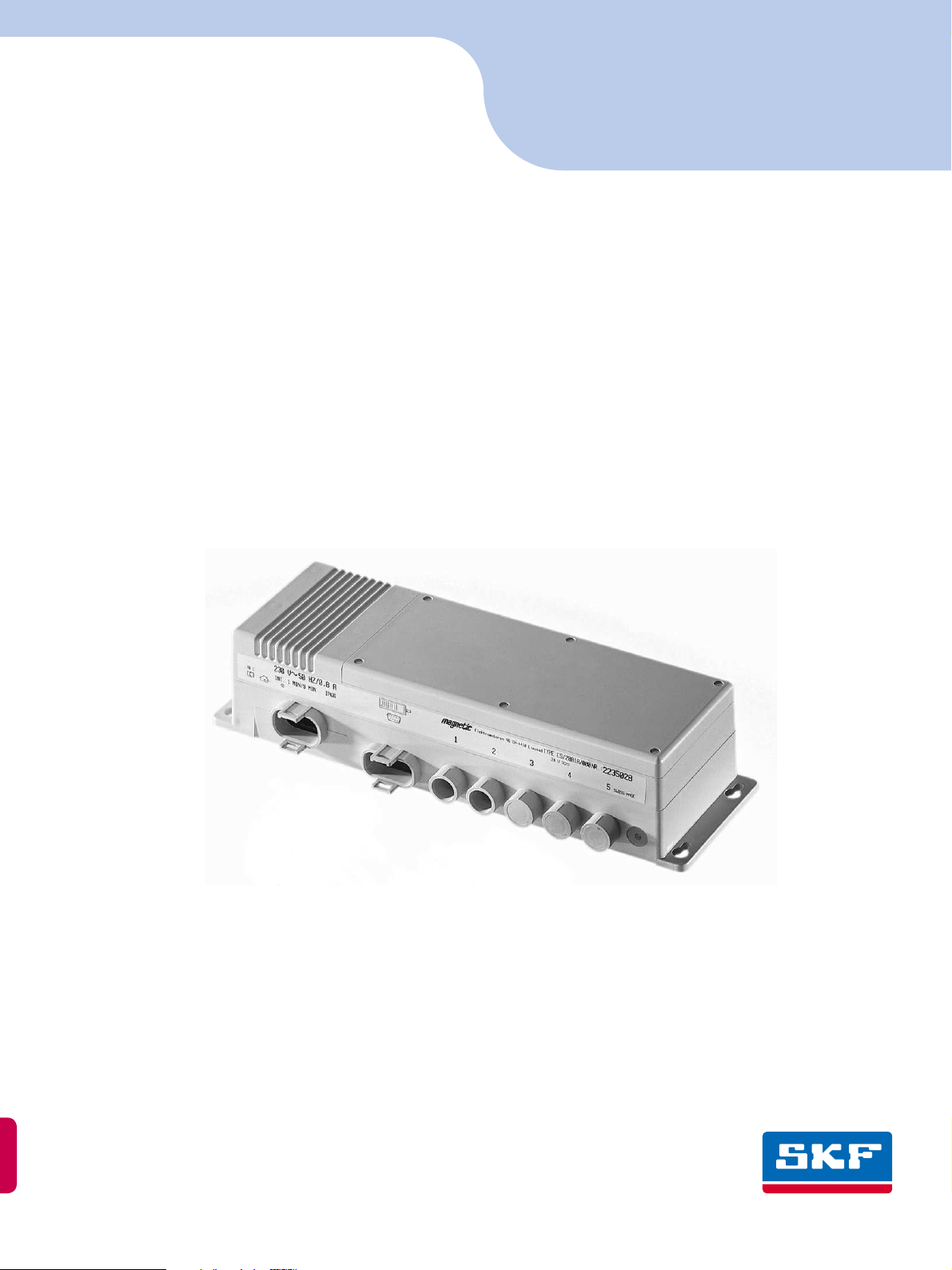
Control unit (Protection class I)
The mains voltage is converted to a 24 V low voltage by a thermally-protected main
transformer. The integral rectifier converts this voltage into direct current.
Economy circuit (standby)
When the actuators are idle, the auxiliary transformer only maintains the control voltage. The main transformer is automatically shut down, thus relieving it of any thermal
load.
First failure safety
To ensure first failure safety, the components which are critical to safety are equipped
with monitoring and supplementary elements. The KOM6 is therefore also equipped
with a microprocessor, motor relays, test circuits and confirmation facility when making inputs.
Toroidal mains transformer (enhanced power)
The toroidal mains transformer is required for enhanced power, e.g. if using more than
two actuators with memory functions.
The toroidal mains transformer must not be used with an internal or external accumulator.
Accumulator
The integrated accumulator is automatically recharged when the control unit is connected to the mains power supply.
This symbol is used to indicate operations and
states which could endanger life and limb or
property.
Follow the instructions precisely!!
This symbol provides the user with useful information.
Der Ringkerntrafo darf nicht mit interner
bzw. externer Akkueinheit betrieben werden.
The earth connection of the control unit is
provided solely as a functional earth for
checking the insulation resistance!
Technical instructions Control unit KOM6
531e2920_0701 Magnetic – The Linear Drives Company™ page 3/11
2.1 Correct usage
The KOM6 has been designed specifically for adjusting beds, chairs and couches in
medical and care applications.
Areas of application include
1. Memory and dependency control units for beds, chairs, couches etc. in which
mechanical collision cannot occur. Thus, the control unit is not required to monitor the system to detect prohibited positions. These applications are suitable for
persons who are not sick and who are not exposed to any hazard due to unsuitable positions.
2. Memory and dependency control units for beds, chairs, couches, etc. where an
external limit switch signals a possible mechanical collision and signals this to
the control unit via the fifth channel in order that the actuators can be switched
off.
If required, Magnetic AG, Liestal, can provide assistance for constructing your products using Magnetic components.
2.2 Ambient conditions
Operation:
Temperature 10°C to 40°C
Humidity max. 85%
Storage / transport:
Temperature -20°C to 40°C
Humidity max. 95%
Duty cycle
Duty cycle 10%; 1min ON / 9min OFF for exit current 5,5 A.
With enhanced power:
Duty cycle 10%; 1min ON / 9min OFF for exit current 9 A.
KB 3min for exit current 12 A.
These devices must not be operated in potentially explosive atmospheres.
The failure of the control unit due to a power
outage or electronic fault must not be allowed
to endanger patients, the operator or service
staff.
Avoid putting patients at risk by using the
memory function.The transducer (encoder) for
the actuators is not first failure safe. Pulses
may be lost.
The first failure safety of the entire system
(e.g. beds, chairs, couches, etc.) is not ensured
only by use of the KOM6. The
entire system must be safeguarded by means
of a separate first failure safe solution.
The entire construction must comply with
DIN 60601-1 and DIN 60602-38.

Technical instructions Control unit KOM6
531e2920_0701 Magnetic – The Linear Drives Company™ page 4/11
3Installation and startup
3.1 Scope of delivery
The KOM6 first failure safe processor control unit consists of the:
control unit
Up to 4 motor connections, 1 mains cable connection and 1 connection for control
devices are possible on the control unit.
The KOM6 is suitable for the following Magnetic actuators:
MAX1 / MAX3 / THG1 / TLG1 / TLT1 (only with toroidal mains transformer)
Options
EMERGENCY STOP function
4x 6V accumulators (internal)
External ACCUPAK accumulator unit
Limit switch connections
Toroidal mains transformer enhanced power (IP30)
Earth connection pin (for protection class II)
Accessories
Control devices
Locking device
Country specific mains cable
3.2 Installation
Fig 1 – Installation
The KOM6 control unit is installed using the four bores provided (Fig. 1). All installation positions are possible.
3.3 Startup
Connecting the mains cable
Fig. 2 – Connection mains cable
2
1
The power plug must be accessible at all
times in order to ensure that the system can
be disconnected from the power supply in the
event of malfunctions.
If Medical standard EN60601-2-38 and
EN1970 must be fulfilled, you have to use
power cable N° 140 422. If not you can use
power cable N° 140 306.
Do not remove the data shield from the
cotrol unit.

Technical instructions Control unit KOM6
531e2920_0701 Magnetic – The Linear Drives Company™ page 5/11
Fit the equipment plug on the mains cable c into the left-hand socket on the control
unit. If the control unit is connected to the mains voltage, the mains voltage indicator
d lights up green.
Connecting control devices
Fig. 3 – Connecting control devices
Fit the D-SUB connector of the control device into the socket provided in the control
unit (Fig. 3).
The control devices used depends on the needs of the system manufacturer. See separate customer-specific documentation. Fig. 3 shows, by way of example, the connection for a handswitch
c, distributor box d with two handswitches and a locking de-
vice SPP6
e.
Fig. 4 – Plug for control device
The cables are strain-relieved and sealed by means of the cast-on cams when plugged
into the socket. The cams engage in the retaining clips.
Connecting actuators
Fig. 5 – Connecting actuators
The actuators (type and number as defined by the system manufacturer) must be connected as follows:
1. Insert the plug (the packing ring washers must no longer be seen)
2. Use the special plug disassembling tool No. 140375 to turn it approx. 30° to the
right up against the stop in order to lock it in position(see Fig. 6).
Ensure that the plugs are fitted at the correct
angle, otherwise the equipment socket may be
damaged. Note the plug shape and arrows
(must point upwards) on the plug!

Technical instructions Control unit KOM6
531e2920_0701 Magnetic – The Linear Drives Company™ page 6/11
Fig. 6 – Connecting actuators
The number of motor connections depends on the customers' needs. Motor connections which are not required are sealed at the factory with waterproof blanking plugs.
These should not be removed.
Initialisation run
The initialisation run is absolutely essential!
Run the actuator(s) using buttons
× and Ø on the handswitch in counter-load direc-
tion as far as the terminal position (= reference point).
Connecting external options
Fig. 7 – Connections for external options
Connection see Fig. 6.
EMERGENCY OFF
The EMERGENCY OFF functions is connected with the jack plug into KOM6 channel 4
or 5 which has been specially prepared for this purpose (optional) (see Fig. 7).
External accumulator
The external accumulator is connected with the jack plug into KOM6 channel 4 or 5
which has been specially prepared for this purpose (optional) (see Fig. 7).
External limit switch
The external limit switch is connected with the jack plug into KOM6 channel 4 or 5
which has been specially prepared for this purpose (optional) (see Fig. 7).
When using a control unit with toroidal
mains transformer, the use of batteries is not
permitted.
All cables must be secured so that no forces
act on the control unit plugs. Plugs which are
poorly aligned may become untight and damage the control unit!
During the initialisation run, run the actuators
a single time to the terminal stop. Note that
the actuators must not be allowed to travel to
the terminal stop on a regular basis.Otherwise
the actuator may be damaged.
The EMERGENCY OFF function has to be tested
regula ry by the user.
The limit switch must not be used as a safety
function

Technical instructions Control unit KOM6
531e2920_0701 Magnetic – The Linear Drives Company™ page 7/11
4Instruction for use
4.1 Operating the handswitch
Fig. 8 – handswitch EHE6
Driving an actuator
Actuators can be driven directly using the buttons in handswitch Area A (Fig. 7).
Button ×:The actuator travels upwards
Button Ø:The actuator travels downwards
The number of buttons depends on the number of actuators and the system manufacturer's specifications.
Programming the memory positions
Buttons P1 to P3 on the handswitch (Fig. 7) can be used to move to positions which
have already been saved in the control unit. This is how to save required positions:
1. Use buttons
× and Ø to move all actuators to the positions that you want to
save under button P1.
(Keep the buttons depressed until you have reached the required position.)
2. Press button M, hold it depressed and also press button P1.
3. Release the two buttons at the same time. Saving will be confirmed by means of
an audible signal.
4. Repeat steps 1 to 3 for programming buttons P2 and P3 if required.
Retrieving memory positions
To retrieve a memory position, press the relevant button P1, P2 or P3 on the
handswitch (Fig. 7)
Hold the button depressed until the actuators have moved into position.
P2
P1
M
P3
A
B
If units are incorrectly operated, the user's
reacti on time mu st not put the pati ent at
risk.
If the memory positions become inaccurate
over the course of time, repeat the initialisation run.
If you let the buttons go, the actuators will
stop directly.

Technical instructions Control unit KOM6
531e2920_0701 Magnetic – The Linear Drives Company™ page 8/11
4.2 Operating the SPP6 locking device
Fig. 9 – locking device SPP6
The locking device can be used to lock or unlock either individual or all actuators.
Locked actuators cannot be operated with the handswitch or footswitch.
Locking an actuator
1. Press the "Lock closed" symbol button g and hold it depressed. The LED c is lit
yellow.
2. Press the motor button
d of the actuator that you want to lock.
3. Release the two buttons.
The operation will be confirmed by means of an audible signal. The actuator is now
locked.
Unlocking an actuator
1. Press the "Lock open" symbol button h and hold it depressed. The LED c is lit
green.
2. Press the motor button
d of the actuator that you want to unlock.
3. Release the two buttons.
The operation will be confirmed by means of an audible signal. The drive can now be
controlled again.
Information about state of locking
Press the button d of the actuator that you want to inform about
If the LED c is lit yellow, the actuator is locked.
If the LED c is lit green, the actuator is unlocked.
Driving an actuator by SPP6
Actuators can be driven directly using the buttons UP ƒ and DOWN „ of the actuator
that you want to drive.on the SPP6.
Button e:The actuator travels upwards
Button f:The actuator travels downwards
(See Technical Data Sheet No. 530D, 2940)
6
3
2
4
1
5
Actuators which are not locked may endanger
patients.
The SPP6 locking device must not be accessible to patients.

Technical instructions Control unit KOM6
531e2920_0701 Magnetic – The Linear Drives Company™ page 9/11
5 Maintenance and cleaning
5.1 Maintenance
The housing and connected cables must be checked periodically (twice yearly) for mechanical damage (e.g. cracks). If any damage is found, disconnect the control unit
from the mains and replace the faulty parts.
Before each connection is made, the sealing rings of the equipment and motor connectors must be checked for damage and, if necessary, they must be replaced.
Apply a thin coating of grease to the sealing rings.
Disconnecting the plugs from the control unit
Fig. 10 – Disconnecting the plugs
To detach the mains and equipment plugs from the control unit, the retaining clips
must be spread with the aid of the Magnetic special plug disassembling tool, Part No.
140375
c. This allows the plugs to be removed d.
To detach the actuators plugs from the control unit, you also have to use the Magnetic special plug disassembling tool, Part No. 140375. See Fig. 11.
Fig. 11 –Disconnecting actuators plugs
5.2 Cleaning
Protection from water, cleaning, disinfecting
The IP66 degree of protection is only guaranteed with plugs fitted.
The KOM6 control unit must only be cleaned with the motors and control switches
properly connected.
If the unit becomes dirty, the housing should best be cleaned immediately in order to
prevent the accretion of residues!
Use a damp cloth and water for manual cleaning. Add a little isopropyl alcohol if necessary.
Do not use any greases other than Klübersynth VR-252 (Magnetic Order No. R50014).
Otherwise, the sealing rings and plastic housing may be damaged.
Ensure you do not spread the retaining clips
too much and break them. Excessive force will
break the retaining clips, with consequent loss
of strain relief and sealing capacity.
It is essential to ensure that no fluid is allowed
to penetrate the connections!The control unit
would be damaged if fluid were allowed to
penetrate.
Washin g water wi th chemic al additi ves must
be pH neutral. Excessively acidic or alkaline
washing water can permanently damage the
metal and plastic components of the control
unit.
High-pressure steam cleansing equipment
must not be used. Magnetic Special Instructions ML 0111/87 must be observed.

Technical instructions Control unit KOM6
531e2920_0701 Magnetic – The Linear Drives Company™ page 10/11
5.3 Accumulators
The accumulator is not a safety-related component, i.e. Magnetic accepts no liability
for the condition of the accumulator. The user is responsible for maintaining accumulators. Magnetic cannot accept consequential damage claims regarding defective accumulators.
Service life
Storing the accumulators in very cold or very hot locations will reduce their capacity
and service life.
Charging internal accumulators
The internal accumulator is automatically recharged when the control unit is connected to the mains power supply.
Charging external accumulators
The control unit is equipped with an audible discharge warning.
The accumulator can be recharged using the KOM6 control unit.
Only battery chargers approved by the manufacturer should be used. The accumulators are protected against overcharging by the current cut-off in the KOM control
units or in the battery charger.
Changing accumulators
Insert the new accumulators into the unit (Fig. 12). Connect them with the connecting wire as shown in the scheme.
Fig. 12 –Akkus auswechseln
5.4 Warranty
Assuming that the operating conditions are complied with and units have no mechanical damage, a warranty of 12 months from the date of delivery will apply for all mechanical and electrical components.
Accumulators are not covered by the warranty.
5.5 Disposal
The control unit components and actuators may be returned to Magnetic AG, Liestal,
for disposal.
Damaged or worn accumulators and chargers should only be replaced by the Magnetic Service Department or trained personnel.
The accumulators should only be recharged in
well-ventilated areas, due to the potential
hazard from the release of explosive gases!
Regular recharging will prolong their service
life.
Accumulators must be recycled, properly disposed of or returned to Magnetic Liestal AG.
They should not be discarded with domestic
refuse .
Please notice the picture on the inner side of
the cover.
The integral accumulator must be recharged
after a maximum storage period of 2-3
months.

Technical instructions Control unit KOM6
531e2920_0701 Magnetic – The Linear Drives Company™ page 11/11
Any work on the units and connections may
only be undertaken when the mains plug has
been disconnected.
5.6 Technical data
Refer to Technical Data Sheet 530D, 2920/0.99.
5.7 Liability
In every case, the owner or operator of the unit shall be liable for its function if the
unit has been incorrectly maintained or repaired by persons who are not employed by
the Magnetic Service Department or if the unit has not been handled in accordance
with its specified application.
Magnetic Aktiengesellschaft shall not be liable for any damage resulting from failure
to observe these instructions. These instructions shall not be regarded as an extension
of the warranty and liability terms set out in the Conditions of Sale and Supply applied by Magnetic Aktiengesellschaft.
5.8 Troubleshooting
Observe the instructions in the relevant customer documentation.
If you are unable to eliminate a fault, contact Magnetic AG, Liestal.
Fault
Cause
Remedy
None of the actuators
are functioning.
No mains voltage supply
(green LED on the housing
does not light up)
Check mains voltage
Check customer's fuse pane
Accumulator control unit
Check charging status
Overheating (excessively
long duty cycle)
Disconnect the control unit
from the mains and let it
cool down for approx. 15
minutes
Error detection (possibly
audible buzzing tone, or red
LED on the handswitch
lights up)
Disconnect the control unit
from the mains for approx.
10 seconds (processor reset
Motors disabled
(yellow LED on the
handswitch lights up)
Enable motors with SPP6
One of the actuators is
not functioning.
Poor connector contact
Re-insert connector
Motor disabled
(yellow LED on the
handswitch lights up)
Enable motors with SPP6
Individual function
does not react
Poor connector contact
Re-insert connector
Loss of data
Move the actuators to the
basic position
 Loading...