

Page 1

USER’S GUIDE
SKC
ENVIRONMENTAL PARTICULATE
AIR MONITOR
MODEL SKC EPAM-5000
DOC# HD50706
SKC Inc.
863 Valley View Road
Eighty Four, PA 15330
Phone: (724) 941-9704
Fax: (724) 941-1369
Manufactured By: Environmental Devices Corporation
Page 2
Model
SKC EPAM-5000
User’s Guide
Page 3

Licenses, Copyrights and Trademarks
This documentation contains trade secrets and confidential information
proprietary to Environmental Devices Corporation (EDC). The software
supplied with the instrumentation, documentation and any information
contained therein may not be used, duplicated or disclosed to anyone, in
whole or in part, other than as authorized in a fully executed EDC End User
License or with the express written permission of EDC.
© 1999 Environmental Devices Corporation. All rights reserved throughout
the world.
Haz-Dust
™
is a registered trademark of Environmental Devices Corporation.
Other trademarks are the property of their respective holders.
ii
Page 4

Safety Notice
Repair of instrumentation supplied by Environmental Devices Corporation
(EDC) should only be attempted by properly trained service personnel, and
should only be conducted in accordance with the EDC system documentation.
Do not tamper with this hardware. High voltages may be present in all
instrument enclosures. Use established safety precautions when working with
this instrument.
The seller cannot foresee all possible modes of operation in which the user
may attempt to utilize this instrumentation. The user assumes all liability
associated with the use of this instrumentation. The seller further disclaims
any responsibility for consequential damages.
iii
Page 5

Warranty
Environmental Devices Corporation (EDC) warrants only non-expendable
products (expendable items include batteries disposable filters and cassettes
or other consumables), parts and labor, for a period of one year from date of
shipment to the original purchaser. The warranty covers only product parts
and labor that failed due to normal operation of the instrument and not due to
abuse or negligence. The product will be delivered in accordance to its
published specifications and free from defects in materials or workmanship.
If a product fails to conform to this one year limited warranty it may be
returned to the factory for repair or replacement of the defected part(s). EDC
must be notified of all returning warranty repair products, either in writing or
by telephone. Shipping and insurance cost will be prepaid by the purchaser.
EDC makes no other express warranty and disclaims any implied warranty of
fitness or merchantability.
iv
Page 6

Table of Contents
Licenses, Copyrights and Trademarks ...................................................................................................................ii
Safety Notice .........................................................................................................................................................iii
Warranty................................................................................................................................................................iv
Table of Contents ...................................................................................................................................................v
Chapter 1 - Introduction to the SKC EPAM-5000 .............................................................................................. 1-1
Introduction to the SKC EPAM-5000 ............................................................................................................... 1-2
Overview of the SKC EPAM-5000 ................................................................................................................... 1-4
Real-Time Dust Monitoring Principles .............................................................................................................. 1-6
Features .............................................................................................................................................................. 1-7
Specifications ..................................................................................................................................................... 1-8
Components........................................................................................................................................................ 1-9
Chapter 2 - Operating Parameters of the SKC EPAM-5000 ............................................................................. 2-1
Turning the SKC EPAM-5000 On and Off........................................................................................................ 2-2
Using the Menu .................................................................................................................................................. 2-3
Setting the Date and Time .................................................................................................................................. 2-4
Setting the Alarm................................................................................................................................................ 2-5
Clearing the Memory.......................................................................................................................................... 2-6
Chapter 3 - Operating the SKC EPAM-5000 ...................................................................................................... 3-1
Selecting the Particle Size..... ............................................................................................................................. 3-2
1.0um Dust Particulates...................................................................................................................................... 3-3
2.5um Dust Particulates..................................... .................................................................................................3-4
10um Dust Particulates………………………………………………………………………………………...3-5
Auto-Zero ......................................................... ..................................................................................................3-6
Manual-Zero....................................................................................................................................................... 3-7
Sampling............................................................................................................................................................. 3-9
Location Codes................................................................................................................................................. 3-12
Reviewing Stored Data..................................................................................................................................... 3-13
Chapter 4 - DustComm Pro V.1.2.......................................................................................................................... 4-1
Introduction to DustComm Pro V.1.2 ................................................................................................................ 4-2
Installing DustComm Pro................................................................................................................................... 4-3
Loading DustComm Pro..................................................................................................................................... 4-4
Menu Selections ................................................................................................................................................. 4-5
File Menu Command ......................................................................................................................................... 4-6
Downloading Data.............................................................................................................................................. 4-8
DustComm Pro Window .................................................................................................................................. 4-11
Translating Data into ASCII Text File. ............................................................................................................ 4-14
Generating a Plot.............................................................................................................................................. 4-15
Data Plot Menu Selections ............................................................................................................................... 4-16
Editing a Title................................................................................................................................................... 4-17
Applying a Correction Factor........................................................................................................................... 4-18
Inability to Download....................................................................................................................................... 4-19
Chapter 5 - Maintenance ........................................................................................................................................ 5-1
Checking the Calibration Span........................................................................................................................... 5-2
Checking the Flow Rate ..................................................................................................................................... 5-5
Adjusting the Flow Rate..................................................................................................................................... 5-7
Battery Maintenance........................................................................................................................................... 5-8
Cleaning the Sensor Optics .............................................................................................................................. 5-11
v
Page 7

Chapter 6 - Troubleshooting .................................................................................................................................. 6-1
If Instrument Does not Respond......................................................................................................................... 6-2
If Memory Full Appears on Display .................................................................................................................. 6-4
Flow Rate Not Achievable ................................................................................................................................. 6-5
Inability to Download Data to PC ...................................................................................................................... 6-6
Appendix A - Menu Screens ...................................................................................................................................A-1
Appendix B - NIOSH/OSHA Particulate Air Monitoring Reference .................................................................B-1
Appendix C - Glossary of Terms............................................................................................................................C-1
Appendix D - SKC EPAM-5000 Accessories ........................................................................................................D-1
vi
Page 8

Chapter 1 - Introduction to Model SKC EPAM-5000
Page 9

Introduction to Model SKC EPAM-5000
Chapter Overview
Introduction
In this chapter
This chapter gives a complete overview of Model SKC EPAM-5000.
This chapter:
• Introduces and describes EPAM-5000.
• Explains operating principles of the EPAM-5000.
• Identifies features, specifications and components of EPAM-5000.
This chapter contains the following topics.
Introduction to the EPAM-5000 1-2
Overview of the EPAM-5000 1-4
Real-Time Dust Monitoring Principles 1-6
Features 1-7
Specifications 1-8
Components 1-9
Chapter 1
Topic See Page
1 -
1
Page 10
Introduction to the SKC EPAM-5000
Introduction
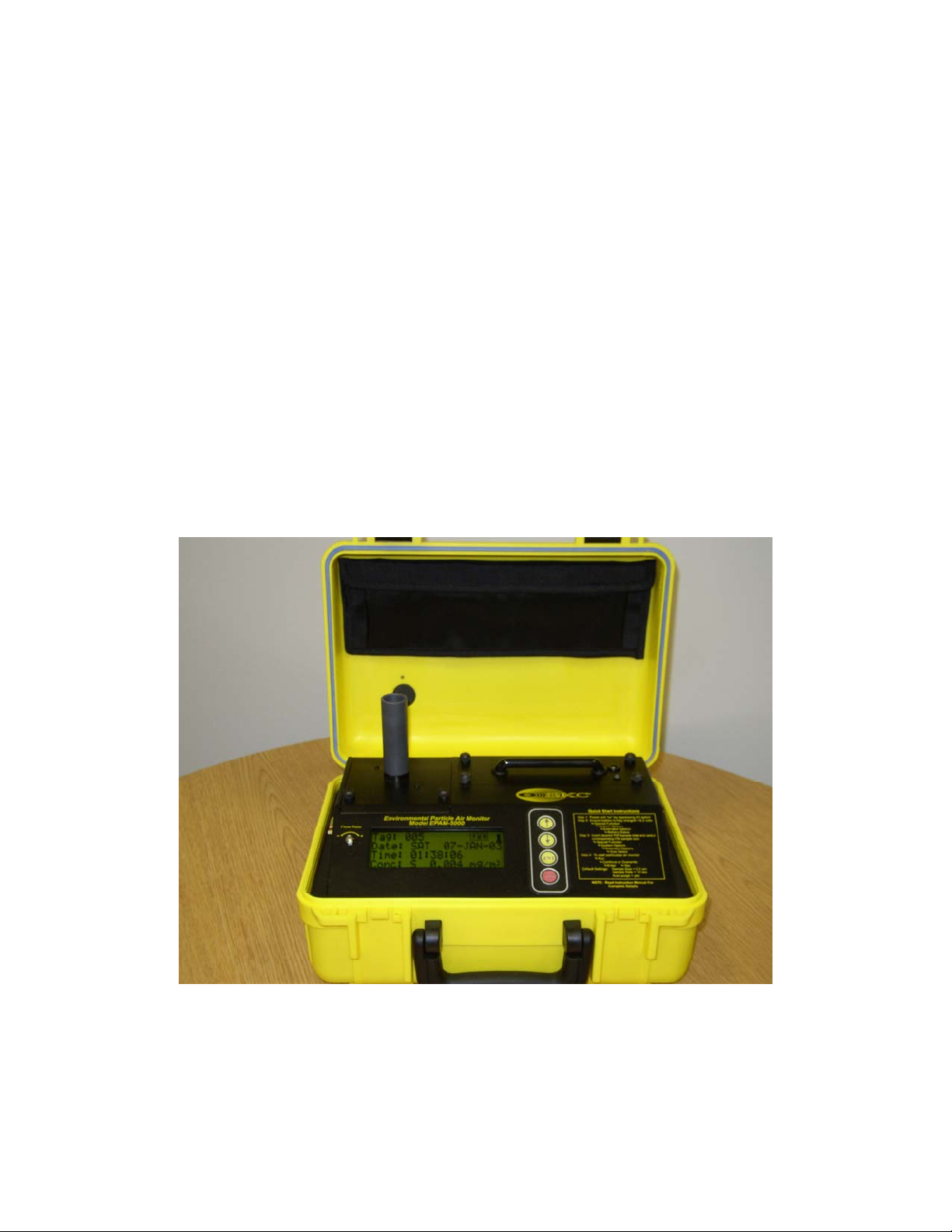
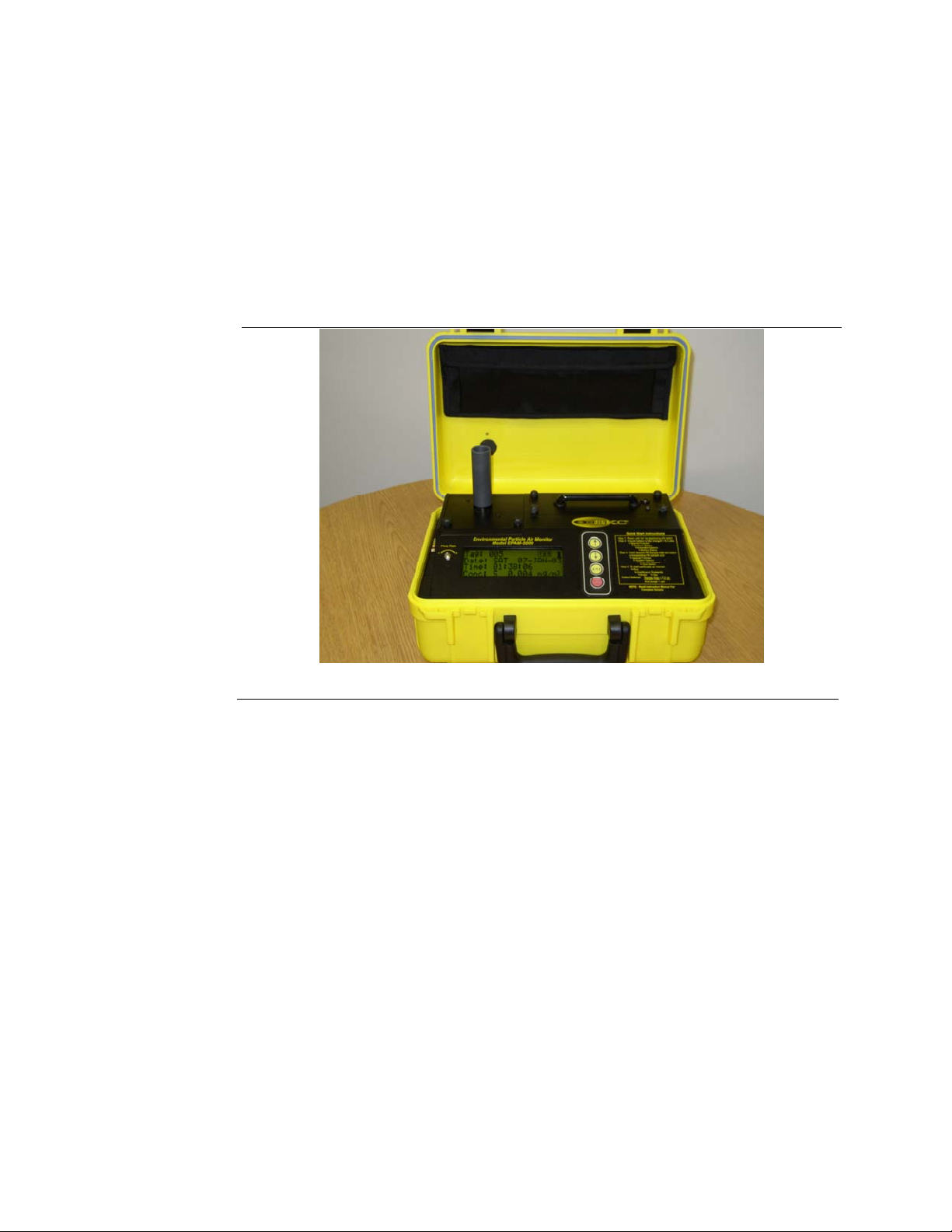
The SKC EPAM-5000 is a high sensitivity real-time particulate monitor
designed for ambient environmental and indoor air quality applications. This
unit combines traditional filter techniques with real-time monitoring methods.
These techniques combined overcome limitations of all other aerosol
monitoring products.
Figure 1.2. Picture of the Haz-Dust.
Continued on next page
1 -
3
Page 11

Introduction to the SKC EPAM-5000, Continued
Comparison of
methods
Description of
traditional
method
Advantages of
traditional
method
Description of
real-time
method
1
The traditional and real-time dust monitoring methods are described below.
Air is drawn by a vacuum pump through a 47mm diameter membrane filter
EPA FRM Style. The fibers and particles collected on the membrane filter
must be counted or weighed in a laboratory for further analysis.
• EPA or OSHA compliance reference method.
• High level of specificity and accuracy.
• Collection of dust particles, which are available for further chemical
analysis.
Dust particles are drawn into the sensor head and are detected once every
second. Dust concentrations are instantaneously calculated and displayed on
the SKC EPAM-5000’s LCD. All data points are stored in memory for later
analysis.
Advantages of
real-time
method
1
• Immediate estimations of the concentration of a contaminant, permitting
on-site evaluations.
• Provision of permanent 24-hour records of contaminant concentrations
using continuous monitors.
• Internal audible alarm to warn workers of approaching hazardous
situations.
• Reduction of number of manual filter tests.
• Reduction of number of laboratory analyses.
• Provision of more convincing evidence for presentation at hearings and
litigation proceedings.
• Reduced cost of obtaining individual results.
1
“The Industrial Environment - It’s Evaluation & Control”, U.S. Department of Health & Human Services, CDC,
NIOSH, 1973.
1 -
4
Page 12
Overview of the SKC EPAM-5000
Ease of use
General
Information
• The user controls all functionality and programming using menus displayed
on a high contrast LCD.
• A 24-hour rechargeable battery capacity.
• Automatic clean air purging of sensor for increased stability and accuracy.
• Internal temperature compensation for ambient use.
• The LCD displays real-time concentration in milligram per cubic meter
(mg/m
3
) in accordance with EPA or OSHA Reference Methods.
• Statistical information of TWA, STEL, Max and Min levels can be viewed
instantly.
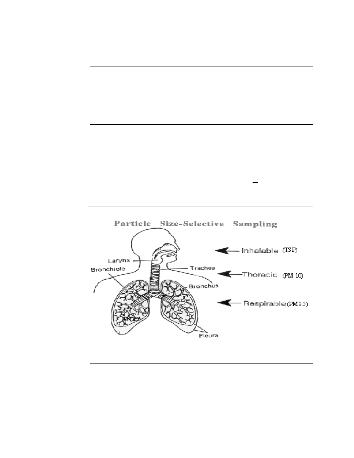
• The SKC EPAM-5000 is calibrated using Arizona Road Dust (ARD)
against NIOSH method 0600 for Respirable dust with a +
• The calibration of the SKC EPAM-5000 can be adjusted to compensate for
changes in particle composition and distribution.
10% accuracy.
Figure 1.4. Diagram showing breathing zones of Inhalable, Thoracic, and Respirable dust
particles.
Continued on next page
1 -
5
Page 13

Overview of the SKC EPAM-5000, Continued
DustComm Pro
Software
DustComm Pro supplied software is designed for more detailed analysis of
sampled data. Pull down menus provide for a user friendly environment
to store and analyze data and print management ready reports
Data can easily be exported in comma-delimited ASCII Text Files
importable into spreadsheet programs such as Microsoft Excel and Lotus
1-2-3.
DustComm Pro Software is used for downloading the information on
Windows XP, 2000, NT, and ME PCs.
The data plots provided with DustComm Pro enable:
· Detailed statistical analysis.
· Creation of graphics and charts.
· Mathematical correction of particle characteristics when aerosol
significantly differs from calibration dust.
1 -
6
Page 14
A
Real-Time Dust Monitoring Principles
Principles
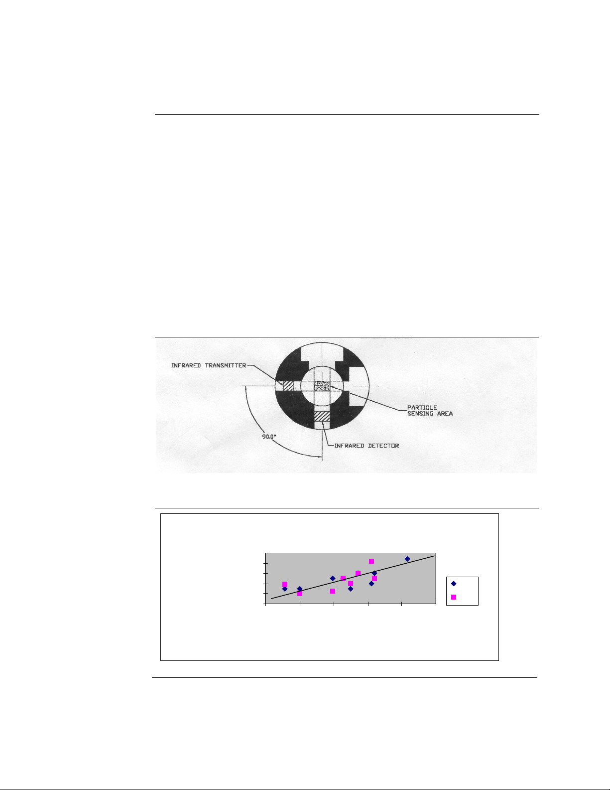
• The SKC EPAM-5000 uses the principle of near-forward light scattering of
an infrared radiation to immediately and continuously measure the
concentration in mg/m
3
of airborne dust particles.
• This principle utilizes an infrared light source positioned at a 90-degree
angle from a photo detector.
• As the airborne particles enter the infrared beam, they scatter the light. The
amount of light received by the photo detector is directly proportional to the
aerosol concentration.
• A unique signal processes internally and compensates for noise and drift.
This allows high resolution, low detection limits and excellent base line
stability.
Figure 1.5. Diagram showing the principle of near-forward light scattering used in the SKC
EPAM-5000.
Light Scattering vs. Gravimetric Filter
1
0.8
0.6
0.4
0.2
Response
0
Relative Optical
0 0.2 0.4 0.6 0.8 1
Gravimetr ic Filter Weight
RD = Arizona Road Dust
RTD = Real-Time Dust
ARD
ARD
0.1
Filter
Figure 1.6. Graph illustrating the principle of near-forward light scattering.
1 -
7
Page 15

Features
Introduction
Real-time
display of
Functional
features
The EPAM-5000 provides a unique combination of features to provide
superior data quality, ease of use, and flexibility to the user. Below is a
partial list of distinctive features.
• Particulate exposure levels.
• TWA, STEL, Min, and Max levels.
• PM 1.0, PM 2.5, PM 10, or TSP.
• Stored data by location code.
• Calibrated to NIOSH methods for lung damaging particles.
• In line concurrent filter samples for gravimetric analysis.
• High sensitivity of 0.001 to 20 mg/m
3
(1 µg/m3 – 2000 µg/m3).
• Interchangeable size-selective sampling inlets.
• Internal air sampling pump.
• Auto purging sensor.
• Easy user access to rechargeable battery and internal filter.
Operational
features
Data
management
• On-screen programming of sampling and data storage parameters.
• Real-time clock.
• User selectable audible alarm.
• In-field zero and span check of instrument calibration.
• Choice of 1 second, 1 minute, 10 second, or 30 minute averaging/storage
intervals.
• Up to 15 months of sample/record time.
• Memory storage of up to 21,600 data points, which can be, distributed into
a maximum of 999 location files.
• Data translation to ASCII text files, importable into Excel or Lotus 1-2-3.
• DustComm Pro software offers comparative graphical and statistical
analysis.
1 -
8
Page 16

Specifications
Introduction
Specifications
Display: Large alphanumeric LCD- 4 line, 20-character display
Operation: Four key splash proof membrane switch – menu driven
Calibration: NIOSH gravimetric method
Sensing range: .001-20.0 mg/m
Particle size range: 0.1-100 µm
Precision: +/- 0.003 mg/m
Accuracy: +/-10% to NIOSH #0600 using ARD
Sampling flow rate: 1.0 – 4.3 liters/minute
Filter cassette: 47mm disposable EPA FRM Style
Alarm output: 90db at 3ft.
Recording time: 1 sec. To 15 months
Sampling rate: 1 sec., 10 sec., 1 min., and 30 min.
Data storage: 21,600 data points
Security code: 4-digit combination
Memory & time storage: > 10yrs
Real-time clock & data display
Data display: concentration in mg/m
& TWA, MAX, MIN, STEL, DATE/TIME
Digital output: RS-232
Operating Temperature: -10
Storage Temperature: -20 to 60
DustComm Pro software: Windows
Power: Rechargeable battery
Operating time: >
Charging time: 22 hours
Humidity: 95% non-condensing
Dimensions (case): 14.0” x 6.0” x 10.0”
Weight: 12 lbs.
The EPAM-5000 meets the following specifications.
3
.01-200.0 mg/m3 (optional)
3
(3 µm/m3)
3
o
C to 50oC
o
C
™
driven for graphical and data translation
24 hours
1 -
9
Page 17
Components
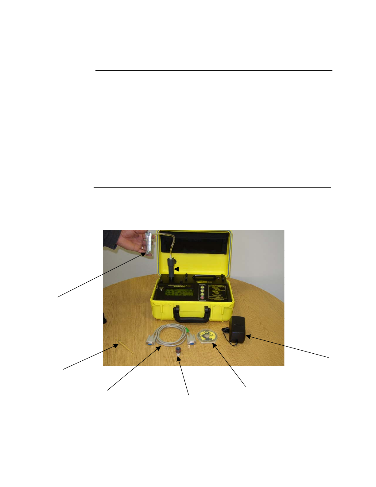
Components
The following components ship with the SKC EPAM-5000.
• SKC EPAM-5000 Monitor.
• Rechargeable battery pack.
• Battery charger.
• Trimming tool.
• EPAM Media CD-ROM Includes: DustComm Pro Software and Instruction
Manual.
• RS232 9-pin serial cable (female to male).
• TSP Sampling inlet (1.0 µm, 2.5 µm, or 10 µm sampling inlet optional.
• Flow Audit Measuring Device Adapter
• Flow Audit Measuring Device.
Figure 1-7 EPAM-5000
Flow Audit
Measuring
Device
Trimming tool
RS232 9-pin
serial cable
Sampling Inlet
Sampling
Inlet
Sleeve
Battery
Charger
DustComm Pro
Software
And Manual
1 -
10
Page 18

Chapter 2 - Operating Parameters of the SKC EPAM-5000
Page 19

Operating Parameters of the EPAM-5000
Chapter Overview
Introduction
In this chapter
This chapter describes the steps involved in starting the EPAM-5000 and
configuring its operating parameters.
Note: The EPAM-5000 is preprogrammed with default settings of 1
minute Sampling rate. If user desires not to change default settings then
the user only needs to turn unit on and press enter button to run monitor.
This allows for immediate sampling for emergency response.
This chapter contains the following topics.
Turning the EPAM-5000 on and off. 2-2
Using the Menu. 2-3
Setting the Date and Time. 2-4
Setting the Alarm. 2-5
Clearing the Memory. 2-6
Chapter 2
Topic See Page
2 -
1
Page 20
Turning the SKC EPAM-5000 On and Off
Introduction
Power-On
Power-Off
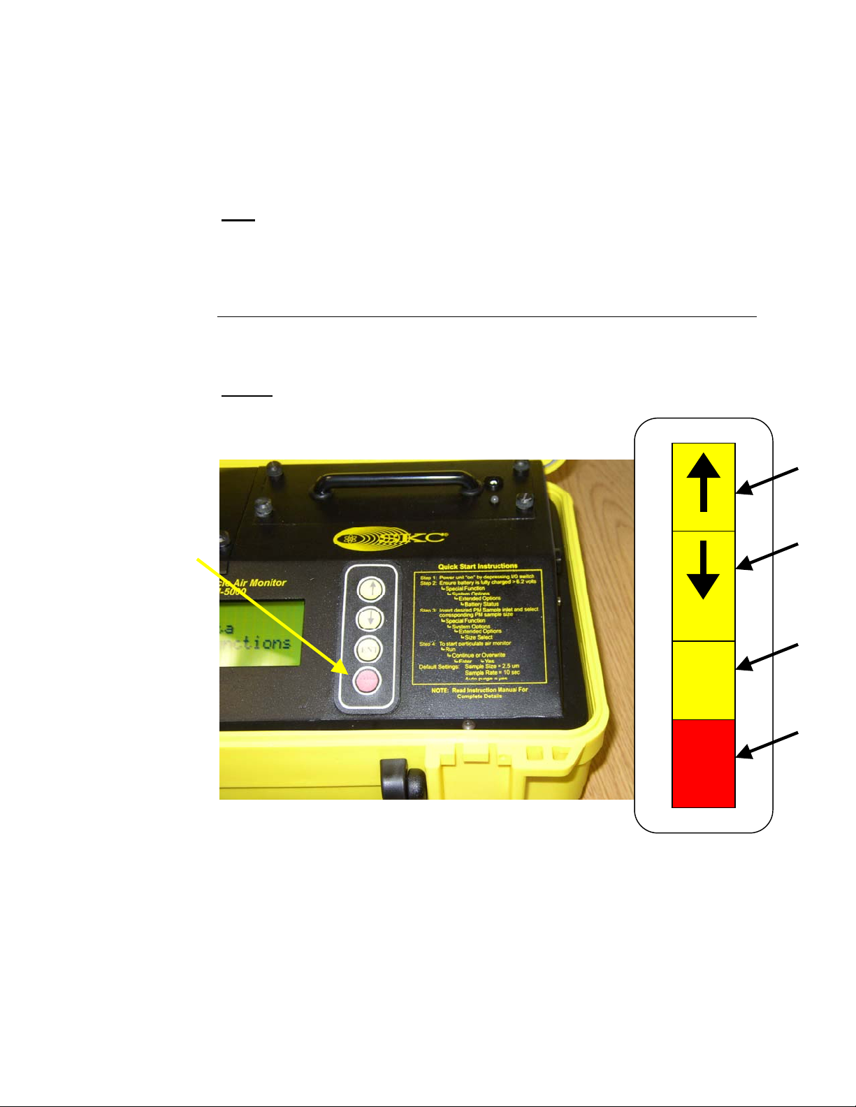
Keypad
Power can be supplied to the SKC EPAM-5000 either from its internal
battery or from the provided AC power transformer (Battery Charger).
Note
: THE BATTERY SHOULD BE FULLY CHARGED before each use. To
charge battery use the EDC supplied charger only. LED indicator on battery
holder will turn green when the battery is fully charged. Charge time is
approximately 22 hours and will run for approximately 24 hours. To check
battery status see Page 5-8.
Press the ON/OFF key to turn the EPAM-5000 monitor on.
Result:
The unit will turn on and the Title Screen will appear.
Press the ON/OFF key a second time to turn the SKC EPAM-5000 off.
Up
Arrow
Down
Arrow
ENT
I/O
Figure 2.1. Diagram of Key Pad on EPAM-5000.
Keypad
Legend
Enter
Button
On/Off
Button
2 -
2
Page 21

Using the Menu
Introduction
Accessing the
main menu
Using the menu
The EPAM-5000 menu appears on the 4x20-character liquid crystal display
(LCD).
Note:
Press ENTER from the Title Screen to access the Main Menu.
The EPAM-5000 is operated using the following menu selections.
<ON/OFF>
<ENTER>
< → >
< ↑ >
< ↓ >
See Appendix A for menu option flow charts.
Selection Function
Turns the EPAM-5000 on and off.
Activates the selected option.
Selection Arrow located on the LCD
display. Indicates the selected menu
option.
Scrolls the Selection Arrow up one
line in a menu list.
Scrolls the Selection Arrow down
one line in a menu list.
EPAM-5000
Particulate
Air Monitor
E.D.C. Ver 1.5 2/99
Figure 2.2. The Title Screen of the EPAM-5000.
→ Run
Review Data
Special Functions
Span Check
Figure 2.3. The Main Menu of the EPAM-5000.
2 -
3
Page 22

Setting the Date and Time
Introduction
Date and Time
settings
View settings
The date and time are pre-set by the factory to Eastern Standard Time and are
maintained by an internal clock. It may be necessary to change the date and
time due to local time zones or daylight savings time.
Note:
It is important that the system date and time are correct for accurate
record keeping.
Time is entered and displayed in military time format.
Date is entered and displayed in European format (i.e., MON 17-DEC-01).
Follow the steps in the table below to check the unit’s date and time.
Step Action
1
2
3
4
Select Special Functions from the Main Menu.
Select Date/Time.
Select View Date/Time.
Result:
Press ENTER to return to the View Date/Time Screen.
The unit’s current date and time will display.
Change settings
Follow the steps in the table below to change the unit’s date and time.
Step Action
1
2
3
4 Enter the correct date and time using the steps in the table below.
5
Select Special Functions from the Main Menu.
Select Date/Time.
Select Set Date/Time.
Increase the value of the selected digit.
Decrease the value of the selected digit.
Select the next digit or field.
Update the selected date and time.
Return to the Date/Time screen without
To... Press...
< ↑ >
< ↓ >
ENTER
Press ENTER when the correct information has been entered.
To... Select...
Set Date/Time
Cancel
saving changes.
2 -
4
Page 23

Setting the Alarm
Introduction
Alarm settings
Using the alarm
An audible alarm can be set to alert the worker of approaching threshold
limits.
The concentration level must be set to the defined agency standard for the
particulate type being sampled.
Note:
See Appendix B for a partial listing of the most common dust
particulates and their corresponding concentration levels.
Follow the steps in the table below to set the alarm level.
Step Action
1
2
3 Enter the appropriate concentration level using the table below.
Increase the value of the
Decrease the value of the
Select the next digit.
4
5 To run unit with alarm select Alm-Continue, or Alm-overwrite to
Select Special Functions from the Main Menu.
Select Set Alarm.
To... Press...
< ↑ >
selected digit.
< ↓ >
selected digit.
ENTER
Press ENTER after the last digit is entered.
activate alarm setting in run mode.
Result:
The alarm has been set and the Main Menu appears.
2 -
5
Page 24

Clearing the Memory
Introduction
Clearing
memory
The memory of the EPAM-5000 can be cleared at any time.
Note:
All data points in all locations will be deleted from memory.
Follow the steps in the table below to clear the memory of the EPAM-5000.
Step Action
1
2
3
4
Select Special Functions from the Main Menu.
Select System Options.
Select Erase Memory.
Select Yes to clear memory.
Note:
memory.
Selecting No will cancel the process without clearing
2 -
6
Page 25

Chapter 3 - Operating the SKC EPAM-5000
Page 26

Operating the SKC EPAM-5000
Chapter Overview
Introduction
In this chapter
This chapter describes and diagrams operation procedures of the EPAM-
5000.
This chapter contains the following topics.
Selecting the Particle Size: 3-2
1.0 micron Dust Particulates 3-3
2.5 micron Dust Particulates 3-4
10 micron Dust Particulates 3-5
Auto-Zero 3-6
Manual-Zero 3-7
Sampling 3-9
Location Codes 3-12
Reviewing Stored Data 3-13
Chapter 3
Topic See Page
3 -
1
Page 27
Selecting The Particle Size
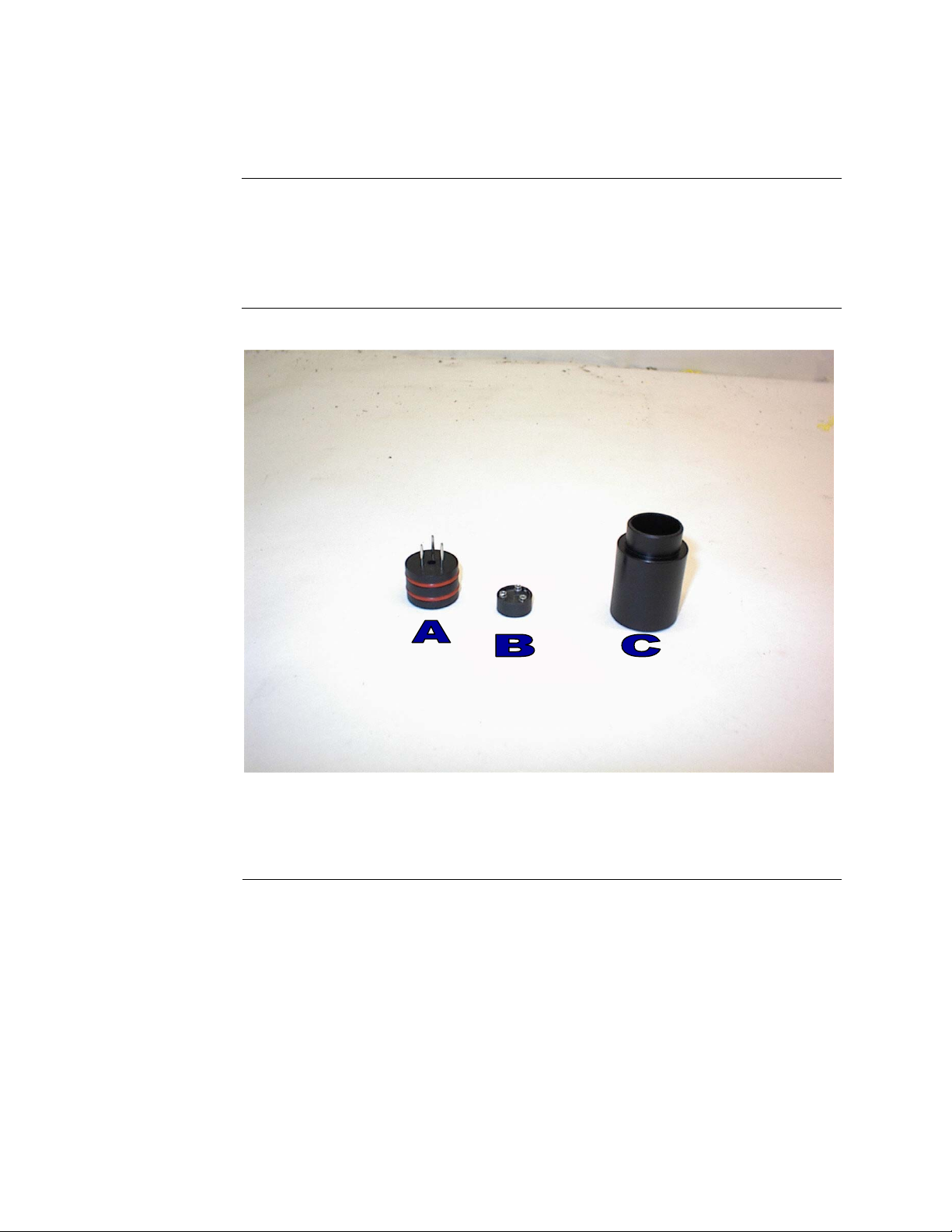
Introduction
The inlet system of the SKC EPAM-5000 can be configured to sample TSP,
PM 1.0, 2.5, 10.0 µm dust particulates. The following pages detail the
selection process for each of these particle types. Impactor Sleeve holds one
optional accessory.
Figure 3-1. Picture: A) Impactor Jet, B) Impaction cup, and C) Impactor
Sleeve. For TSP sampling use impactor sleeve without impactor.
One Size Selective Inlet is provided with EPAM-5000. Impactors are engraved
on bottom of jet.
3 -
2
Page 28

1.0um Dust Particulates
Follow the steps in the table below to select PM-1.0 dust particulates.
Step Action
1
2
3
4
5
6 Insert the sampling inlet into the sensor head of the
7 Attach the filter cassette to the sensor head of the EPAM-5000.
8 Turn to page 3-7 and follow the instructions to Manual-Zero the
Select Special Functions from the Main Menu.
Select System Options.
Select Extended Options.
Select Size Select.
Select 1.0 µm – E (The letter E will be displayed on LCD during
run mode to identify for the user that 1.0 µm has been selected.)
Result:
EPAM-5000.
Note:
samples place a clean gravimetric filter in the filter cassette. The
flow rate should be checked each time a new gravimetric filter is
used. See page 5-5 for information on checking the flow rate.
See diagram below.
EPAM-5000.
The Main Menu is displayed.
If also collecting concurrent 47mm EPA FRM Style filter
Install 47mm filter if
desired.
Remove filter holder
by unscrewing
bottom round cover.
Figure 3-2. Diagram of sensor lid. To unlock sensor lid unscrew pem screw
located on right side of sensor lid to expose the filter cassette. *NOTE: When
closing sensor cover be sure not to tighten pem screw too tightly the spring
inside the screw can break.
3 -
3
Page 29

2.5um Dust Particulates
Note: 2.5-µm size select is the default setting of the EPAM-5000.
Follow the steps in the table below to select PM2.5 dust particulates.
Step Action
1
2
3
4
5
6 Insert the inlet into the sensor head of the EPAM-5000.
7 Attach the filter cassette holder to the sensor of the EPAM-5000.
8 Turn to page 3-7 and follow the instructions to Manual-Zero the
Select Special Functions from the Main Menu.
Select System Options.
Select Extended Options.
Select Size Select.
Select 2.5.
Result:
Note:
samples place a clean gravimetric filter in the filter cassette. The
Flow Rate should be checked each time a new gravimetric filter is
used. See page 5-5 for information on checking the flow rate.
EPAM-5000.
The Main Menu is displayed.
If also collecting concurrent 47mm EPA FRM Style filter
3 -
4
Page 30

10um Dust Particulates
When using the SKC EPAM-5000 monitor for PM-10 sampling a suitable
entry must be used.
Selecting PM10
Follow the steps in the table below to select PM-10 dust particulates.
Step Action
1
2
3
4
5
6 Insert the inlet into the sensor head of the EPAM-5000.
7 Attach the filter cassette holder to the sensor of the EPAM-5000.
8 Turn to page 3-7 and follow the instructions to Manual-Zero the
Select Special Functions from the Main Menu.
Select System Options.
Select Extended Options.
Select Size Select.
Select PM10.
Result:
Note:
samples place a clean gravimetric filter in the filter cassette. The
Flow Rate should be checked each time a new gravimetric filter is
used. See page 5-5 for information on checking the flow rate.
See figure number 3-2 on page 3-3.
EPAM-5000.
The Main Menu is displayed.
If also collecting concurrent 47mm EPA FRM Style filter
Continued on next page
3 -
5
Page 31

Auto-Zero
Introduction
Auto-Zero
Auto-Zero purging feature automatically adjusts for baseline drift due to
severe ambient temperature change.
This feature is a default setting on the EPAM-5000.
The Auto-Zero feature purges the sensor optics with clean air and reestablishes the baseline every 30 minutes.
To deactivate or reactivate the Auto Zero purging feature follow the table
below.
Step Action
1 Select Special Functions from the Main Menu.
2 Select System Options.
3 Select Extended Options.
4 Select Calibration Options.
5 Select Auto Zero.
3 -
6
Page 32

Manual-Zero
Introduction
Manual-Zero
Manual-Zero sets the measurement baseline of the EPAM-5000 to zero
mg/m
set of measurements.
Note:
zeroes baseline every 30 minutes.
Follow the steps in the table below to Manual-Zero the EPAM-5000.
Note:
in Chapter 5 Section 8.
3
. The Manual-Zero check should take place prior to beginning a new
If using the Auto-Zero setting (default) the EPAM-5000 automatically
The battery should be fully charged. Check battery status as described
Step Action
1 Be sure the appropriate sampling inlet is attached to the sensor
inlet of the EPAM-5000 using the table below.
If sampling… Then insert the…
PM1.0 Particulates 1.0 impactor jet
PM2.5 Particulates 2.5 impactor
PM10 Particulates 10 impactor jet
TSP Particulates Impactor sleeve only
Continued on next page
3 -
7
Page 33

Manual-Zero,
Continued
3
4
5
6
7
Select Special Functions from the Main Menu.
Select System Options.
Select Extended Options.
Select Calibration.
Result:
Select Manual-Zero.
Select Manual-Zero again.
Note:
executes the steps necessary to reestablish the baseline.
Result:
process is complete.
Notes:
The EPAM-5000 has an auto zero purging feature that
automatically purges the sensor and performs an auto zero to
reestablish the baseline approximately every 30 minutes. An X
inside a box appears in right hand corner of the display when the
instrument is auto zeroing.
Screen appears with manual zero at the top.
Wait approximately 99 seconds. The unit automatically
The Main Menu is displayed when the manual-zero
3 -
8
Page 34

Sampling
Introduction
Conditions
Once you have selected a Particle Size and completed the Manual-Zero
process the EPAM-5000 is ready to begin sampling.
The following conditions should be met before starting the sampling process.
Condition... For further Information
See Page...
The correct particle size must be selected. 3-2
The correct sampling inlet must be attached. 3-2 –3-5
The date and time must be checked and/or set. 2-4
The Manual-Zero process must be complete. 3-7
The alarm level must be set if sampling with
2-5
the alarm feature.
Sampling
Follow the steps in the table below to begin the particle sampling.
Step Action
1 Turn unit on and press enter.
2 Select Run, and Choose Continue or Overwrite data.
3 Choose the memory storage type using the table below.
Erase all previously recorded
To... Select...
Overwrite, then
data points in all locations.
Select Yes to confirm,
Note:
Selecting No will
cancel sampling process
without effecting memory.
Add data points to the next
Continuation.
consecutive location.
Note:
See page 3-13 for explanation of location codes.
Continued on next page
3 -
9
Page 35

Sampling, Continued
4 Sample and record the data using the table below.
Without the alarm feature
With the alarm feature
A
To Sample... Select...
Run
Alm-Continue
Results:
• The internal pump is activated and the sampling process begins.
• The Run Screen is displayed.
Note:
Maximum sampling time is based on the sampling interval
selected in step number two.
D
B
Figure 3.10. The Run Screen. The table below describes the diagram details.
C
3 -
10
Page 36

Sampling, Continued
Detail Explanation
A Indicates Location Code of data being sampled. A record
B Particulate type being sampled.
C Concentration. A constant negative number may indicate the
D Battery Status Bar is displayed in the upper right hand corner
Ending the
Sampling
process
Press ENTER to stop data collection and return to the Main Menu.
Note:
The EPAM-5000 default settings are for a size select of 2.5 µm, 1 min.
sample rate with auto zero purge on.
should be kept of the site that corresponds to each location
code.
Note:
See page 3-11 for explanation of location codes.
1.0 µm = E
2.5 µm = S
10 µm = M
TSP = L
baseline of the unit is not set to zero and the Manual-Zero
process should be performed or Auto Zero function should be
turned on see Chapter 3 page 3-6.
when the unit is in the run mode. This status is a relative
indicator of battery voltage versus time.
Selecting the
Sample Rate.
Follow the steps in the table below to select the sample rate.
Step Action
1
2
3
Select Special Functions from the Main Menu.
Select System Options.
Select Sample Rate.
Select... For maximum sampling time of...
1 Second 6 Hours
10 Seconds 60 Hours
1 Minute 15 Days
30 Minutes 15 Months
Note: A sample is taken each second and averaged by the sample
interval time selected.
3 -
11
Page 37

Location Codes
Introduction
Maximum
location codes
Assigning
location codes
The EPAM-5000 assigns a location code called tag number to each sampling
sequence. The active location is indicated in the Data Record Screen (See
figure 3.10).
The EPAM-5000 can store a total of 21,600 data points, which can be
distributed into a maximum of 999 locations.
The location code assigned to the site is determined by the memory storage
type selected in step number three of the sampling process (page 3-9).
Use the table below to identify the location code being used.
Data storage type selected... The SKC EPAM-5000 Assigns...
Continuation
Overwrite
The Next Consecutive Value as the
Location Code.
Example:
If data was previously stored
in Tag #001 and #002 the data being
collected will be stored in Tag #003.
001 as the Tag Number and all previously
stored data points in all locations are
erased.
3 -
12
Page 38

Reviewing Stored Data
Introduction
LCD display
Viewing data
on the LCD
The EPAM-5000 provides extensive capabilities for reviewing internally
stored data and statistics on the LCD or downloading to a PC using
DustComm Pro Software (Chapter 4).
The following information can be displayed on the LCD.
Display Description Tag #
Date Date of sampling.
Start Time sampling began.
Stop Time sampling was terminated.
Time Time of occurrence of reported statistic.
MAXIMUM Sample Highest concentration of dust particles.
MINIMUM Sample Lowest concentration of dust particles.
T.W.A. Time weighted average concentration of dust
particles.
Elapsed Elapsed time of the time weighted average.
S.T.E.L. Short-term exposure limit.
Follow the steps in the table below to review stored information and statistics.
Step Action
1
2
Select Review Data.
Select Statistics.
3 Determine your next step using the table below.
Memory holds data points in
Memory has been cleared of
If... Then the...
The Scanning Memory
other locations.
Screen displays. Go to step 7.
No Data Recorded.
all data points.
4 Select the Location using the table below.
A different Location
To review... Select...
New Tag XXX and go to step
7.
Continued on next page
3 -
13
Page 39

Reviewing Stored Data, Continued
5 Enter the desired Location in the Location Select Screen using the
table below.
Increase the value of the selected digit.
Decrease the value of the selected digit.
Select the next digit or field.
6
7 The first of five statistics screen appears when data is computed.
To... Press...
Press ENTER when the desired location code has been entered.
Result:
being reviewed for the first time scrolling dots will appear
indicating the microprocessor is computing data.
Scroll through the statistics screens using the table below.
The location is shown on the display. If the location is
Press... To Scroll...
< ↓ >
< ↑ >
Forward through the statistic screens.
Backward through the statistic screens.
< ↑ >
< ↓ >
ENTER
To download data to a PC using the provided DustComm Pro Software select download from
review data menu and proceed to Chapter 4.
3 -
14
Page 40

Chapter 4 – DustComm Pro V.1.2
Page 41

Introduction to the DustComm Software
Introduction
Spreadsheet
applications
Data plots
DustComm is a powerful and flexible Windows application software package
designed for use with the SKC EPAM-5000 Monitor.
DustComm is both communications software that enables stored project data
to be downloaded to a PC, and a data manipulation tool, enabling detailed
analysis and reporting of sampled data.
DustComm easily translates data into spreadsheet ASCII text files. These
files can be open into spreadsheet programs such as Microsoft Excel
The data plots provided with DustComm enable:
• Detailed statistical analysis.
• The creation of graphics and charts.
• The mathematical correction of particle characteristics when aerosol
significantly differs from calibration dust.
4-
2
Page 42

Installing DustComm
Introduction
Minimum
system
requirements
Software
installation
DustComm installation is easy and quick, the entire process should take less
than 5 minutes.
Windows ME or Higher.
4 MB available disk space.
8 MB RAM.
Follow the steps in the table below to install DustComm.
Note:
It is assumed that the CD-Rom Drive is the “D” Drive. Substitute D
with the appropriate drive letter if necessary.
Step Action
1 Start Windows.
2 Close all open applications.
3 Insert Installation Disk into the D drive.
4 Open My Computer
5 Select the folder named “DustComm V1.2” and double click to
enter.
6 Select the icon named “Setup” and double click. See Figure1.
7 Follow the installation wizard steps.
Figure 1: DustComm Software Folder with “Setup” Selected in Windows XP.
4-
3
Page 43

Loading the DustComm Software
Windows ME
Windows NT,
2000 & XP
Follow the steps in the table below to load the DustComm software if using
Windows ME.
Step Action
1 Select the Start Menu.
2 Select Programs.
3 Select the folder EDC DustComm Pro 1.2
4 Select DustComm Pro 1.2
Follow the steps in the table below to load the DustComm Software if using
Windows NT, 2000 & XP.
Step Action
1 Double Click on the icon on your desktop.
NOTE: If shortcut icon does not appear on desktop follow the
steps for Windows ME.
Figure 2. DustComm Screen immediately after loading software.
4-
4
Page 44

d
Menu Selections
Introduction
Figures 3 through 5 show each of the DustComm menu options.
Note:
If a menu option is displayed in light type it is not available during the
current task.
Opens Saved Files
Saves Current Open Files if changed
Saves Current Open Files, that have not yet been saved
Closes Open Files
Saves Current Open Files as a text file, so that you can
open the data up in a spreadsheet
Exits the entire Program
Figure 3. File Menu Options.
Downloads Instrument
Figure 4. Unit Menu Options.
Selects Instrument and Com Port that you want to
downloa
Write Notes about the Open File
Print Current Open Location
Figure 5. Location Menu Options.
Figure 6. Plot Menu Options.
Figure 7. Help Menu Options.
Review the data in a statistical graph that was previously
saved
Register the DustComm Software and Instrument
Information about DustComm Pro 1.2
4-
5
Page 45

File Menu Commands
Introduction
Opening an
existing project
folder
Saving a
project folder
Use the File Menu option to open, save, print, close and export sampled data.
You can also use the File Menu to Exit the DustComm Pro Software
Notes:
• Data is sorted by time collected.
• Data points are reported in mg/m
Follow the steps in the table below to retrieve stored project data.
NOTE: A sample .dcm file is preloaded for review of software options.
Step Action
1
2
Select File.
Select Open.
3 Double click on the desired Project Folder.
Note:
DustComm will save all files in My Documents, or user
selected folder.
Follow the steps in the table below to store project data.
Step Action
1
2
Select File.
If... Then Select...
• Saving the data in the project
folder for the first time, or,
• Saving an existing folder to a
new name or location.
Saving an updated version of an
existing project folder to the same
file name and location.
Result:
file name is displayed in the title bar. Only with Save As with the
data have a new file name and location if selected.
3
.
1. Save As, then,
2. Type a file name for
the project file.
3. Select OK.
Save
The data is saved in the new project folder and the new
Continued on next page
4-
6
Page 46

File Menu Commands, Continued
Exit software
Exit DustComm Pro Software in one of two ways.
Option
number
1
Or
2 Single click on the “X” in the upper right hand corner of the
1. Select File.
2. Select Exit.
screen.
Action
4-
7
Page 47

Downloading Data
Introduction
Downloading
data
Connect the
cable
Preparing the
PC
Internally stored data can be downloaded to DustComm for detailed analysis.
The three major steps used to download data from the dust-monitoring unit to
a PC are listed below and detailed in the next few pages.
1. Connect the cable.
2. Prepare the PC for data transmission.
3. Prepare the dust-monitoring unit for data transmission.
Follow the steps in the table below to connect the cable for data transmission.
Step Action
1 Connect one end of the supplied RS232 cable to the dust-
monitoring unit.
Note:
serial to USB adapter.
2 Connect the other end of the RS232 cable to the appropriate
COMM port on the PC.
Note:
connection can disrupt data transmission.
Follow the steps in the table below to prepare the PC for data transmission.
Note:
Multiple locations will be separated by tabs at the bottom of the
program.
Step Action
1 Open DustComm.
2
3
Select Unit and Select Properties.
Under the Properties selection choose your unit and the Com Port
that you want to connect. Press Ok when you are finished
4
Select Unit and Select Download.
5 When the items above are finished you should see the download
box appear.
If USB compatibility needed you will need to purchase a
Check that both connections are secure. An intermittent
Continued on next page
4-
8
Page 48

Downloading Data, Continued
Preparing the
unit.
Follow the steps in the table below to prepare the unit for data transmission.
Step Action
1
Select Playback or Review Data (depending on your instrument)
from the Main Menu on the unit.
2
3
4
Select Download.
Select To Dust Data Collector.
Press ENTER.
Result:
The Transmitting window appears.
Note:
Bars on the PC screen should increase as the unit
downloads.
5 When the transmission is complete...
• The To Dust Data Collector selection screen is displayed on
the units monitor. The unit may be shut off at this time.
• The downloaded data is displayed in the Project Folder on the
PC. (Figure 8).
Figure 8. Project File after data has been transmitted.
4-
9
Page 49

DustComm Pro Window
Introduction
Each section of the DustComm Pro Window will explain a different part of
the statistics.
Location
Information
Dataset
Information
The Location information will give you general details about the
downloading statistics. Such as date, time, start/stop time, data rate, duration,
how many samples where downloaded and the unit. There is also box so that
you can name the location and a shortcut to type in any notes you would like
to add.
Figure 9. Location Information section of the DustComm Pro Window.
The Dataset Information will tell you more specific information about the
downloaded statistics. Such as type of data, the average, the Max/Min
Sample and the Max STEL.
Figure 10. Dataset Information section of the DustComm Pro Window.
Continuted on the next page
4-
10
Page 50

DustComm Pro Window, Continued
Dataset Scale
Factor
Quick Plot
The dataset scale factor section of the DustComm Pro Window, is so that you
can adjust the scale to be equal to your specific type of dust. You can read
more about adjusting the scale factor on page15.
Figure 11. Dataset scale factor section of the DustComm Pro Window.
The Quick Plot graph shows you a miniature version of the Full Plot. The
Full Plot button is located directly below Quick Plot can you can read more
about Full Plot on pages11-14.
Figure 12. Quick Plot & Full Plot Button on the DustComm Pro Window.
4-
11
Page 51

DustComm Pro Window, Continued
Location Data
The location data section shows you the milligrams per cubic meter you
sampled for and the times that they were sampled at.
Figure 13. Location Data on the DustComm Pro Window.
4-
12
Page 52

Translating Data to an ASCII Text File
Introduction
Translating
data
Project Data must be translated into ASCII text format before it can be read
by a spreadsheet application.
Follow the steps in the table below to Translate Project Data into ASCII Text
format.
Note:
A Project Folder must be open to access the translate feature.
Step Action
1
2 Select Export.
3 An “Export Locations” Window will appear. Select either All for
4 An “Export To…” Window will appear. Type in the name that
6 When you are ready to open the data in a spreadsheet application.
Select File from the Main Menu.
all locations or select the range of locations you would like to
export. Click OK when you have selected your locations.
you would like to call your exported data and click Save.
Open the spreadsheet program go to the Open menu, select all
files under type of file name and double click on the file you want
to review. This will result in your saved data opening in your
spreadsheet program.
Figure 14. Exported Excel information.
4-
13
Page 53

Generating a Plot
Introduction
Generating a
graph
A graph can be plotted with full plot located at the bottom of the DustComm
Pro Window.
Follow the steps in the table below to generate a graph using the DustComm
Plot menu selections.
Step Action
1
2
3 The result is graph will be plotted to the screen (see figure 15
Select Plot.
Select Review. This option is for graphs that have already been
saved.
Note: For new statistics click on the “Full Plot” Icon on the
DustComm Pro Window.
below).
Continued on next page
4-
14
Page 54

Data Plot Menu Selections
Introduction
At the top of the data plot will be a button bar. Below is an explanation of
what each button does.
Number Function
1 Saves plotted information as a DustComm Pro Chart (*.dcc).
2 Copies plot to a bitmap file.
3 Edits the title of the plot.
4 Page Setup Properties.
5 Prints the current plot.
6 Zooms into plot. By Highlighting from point to point that you want
zoomed in on.
7 Returns to full screen of plot.
8 Adds or removes vertical lines.
9 Adds or removes horizontal lines.
10 Select the specific type of graph, i.e. bar or line graphs.
11 Changes color of the graph.
111098 7 6 5 4 3 2 1
4-
15
Page 55

Data Plot Menu Selections, Continued
Number Function
1 Pointer tool.
2 Insert Squares.
3 Insert Ovals.
4 Insert arrows.
5 Insert arched lines.
6 Insert a picture. Choose the size of your picture and then right
click on the box and select properties. Select the picture tab and
select picture. The picture you chose will appear in the box.
7 Insert a text box.
8 Insert a callouts with text.
9 Change the color of your squares, ovals, text boxes and callouts.
10 Change the color of the text in your text boxes and callouts.
11 Copy squares, ovals, text boxes and callouts.
12 Paste squares, ovals, text boxes and callouts.
13 Bring squares, ovals, text boxes and callouts to front.
14 Send squares, ovals, text boxes and callouts to the back.
15 Group squares, ovals, text boxes and callouts.
16 Ungroup squares, ovals, text boxes and callouts.
17
18 Flip over up and down squares, ovals, text boxes and callouts.
19 Rotate squares, ovals, text boxes and callouts clockwise.
20 Rotate squares, ovals, text boxes and callouts counterclockwise.
21 Properties of selected squares, ovals, text boxes and callouts.
Flip over left to right squares, ovals, text boxes and callouts.
15 16 17 18 2120 19141312111098 7 6 5 4 3 2 1
4-
16
Page 56

Editing Title
Introduction
Editing the title
A customized title can be added to a graph before printing.
Follow the steps in the table below to add a title to the graph.
Step Action
1 Have location plotted already.
2
Select the Edit Title button on the menu bar.
3 A Window will appear where you can edit the title for what you
would like its name to be.
4
Select OK when the correct title is in the box.
Result:
The graph will be created with the new caption.
Figure 16. Edit Title Window.
4-
17
Page 57

Applying a Correction Factor
Introduction
Calculating a
correction
factor
Applying a
correction
factor
A correction factor can be applied to the data collected with the unit to
account for variances in gravimetric readings.
The correction factor is calculated by dividing the Gravimetric reading by the
unit reading.
Follow the steps in the table below to apply a correction factor to all data
points in the current project folder.
Step Action
1
Select the 2nd Scale= with a box where you can type in your scale
factor.
2 Type in the Scale factor.
3 After the scale factor is entered press enter.
Result:
All data points in the project folder have been multiplied
by the correction factor.
Removing the
correction
factor
Follow the steps in the table below to remove the correction factor from the
data points in the project folder.
Step Action
1
Select the 1st Scale= under the Dataset Scale Factor.
Result:
Data points should return to original state.
4-
18
Page 58

Inability to Download Data to PC
Introduction
If DustComm Software installs properly but downloading instrument to
computer is unsuccessful try the following:
• Ensure that the RS232 cable connectors from the PC are tightly
screwed into place.
• Ensure that the communications settings are set appropriately in the
Download Properties screen of the DustComm program. Select Unit,
Properties to access this dialog box. The communications port must be
set to the appropriate Com Port used on the PC.
• If you are experiencing problems downloading your unit’s results to
your PC, and the RS232 cable connectors are secured tightly, your
cable may be connected to the wrong 9-pin port on your PC. If your
PC has more than one 9-pin connection port, attach the cable to
another 9-pin port and try to download the dust monitor’s results at
that port. You may need to try all of your PC’s 9-pin ports before
finding the correct connection.
• If the previous steps check out, try using the Windows supplied
HyperTerminal or other appropriately configured communications
software to receive data when downloading from the SKC EPAM-5000
Monitor.
• If using a USB port make sure you are using the proper USB to serial
adapter.
For service or Technical Questions please call 800-234-2589 or e-mail
techsupport@hazdust.com
Page 59

Chapter 5 - Maintenance
Page 60

Chapter Overview
Introduction
In this chapter
This chapter covers the routine maintenance procedures for the SKC EPAM-
5000.
This chapter contains the following topics.
Checking the Calibration Span. (Optional Accessory). 5-2
Checking the Flow Rate. 5-5
Adjusting the Flow Rate. 5-7
Battery Maintenance. 5-8
Cleaning the Impactors 5-11
Cleaning the Sensor Optics. 5-12
Chapter 5
Maintenance
Topic See Page
5 -
1
Page 61

Checking the Calibration Span
Introduction
When to check
the calibration
span
Conditions
The Span Reference Insert Part Number CS-105 is a light scattering device
that provides a constant value (termed a “k” factor).
The Span Reference should be used as a reference to check factory calibration
of the EPAM-5000 Monitor.
The calibration span should be checked under the following conditions:
• Once a month with normal usage. (Normal use is twice a week).
• If the EPAM-5000 is dropped or otherwise damaged.
• The first time you use the unit to double check the factory calibration.
Note
: The EPAM-5000 can be sent to SKC. Annually recalibration
recommended in accordance with ISO and NIST procedures.
The following conditions must be met before checking the calibration span.
Condition... For further information
The Sensor Optics must be clean. 5-11
The Environment must be clean. --The Battery must be fully charged. 5-7
see page...
Figure 5-1. Inserting CS-105 into SKC EPAM-5000 Sensor.
Continued on next page
5 -
2
Page 62

Checking the Calibration Span, Continued
Checking
Calibration
Span
Follow the steps in the table below to check the Span of the EPAM-5000
Monitor.
Note:
Failure to follow this procedure in its entirety may cause an incorrect
“k” value reading.
Step Action
1 Turn monitor on.
2 Run monitor on a 1 (one) second sample rate for (5) minutes. See
Chapter 3 Page 3-9 Sampling.
3 With unit running select down arrow from keypad to activate Auto
Purge. An “X” will appear in the upper right hand corner to
indicate sensor is purging. See Chapter 3 Page 3-6 Auto Zero
Purge if more detailed information is needed.
4 After Auto Purge is complete (x is no longer present on screen)
select enter to stop monitor from running.
5 Performing the Span Check.
5-1
5-2
Step Action
Select Span Check from Main Menu.
Select Yes to proceed with span check (all data will
be lost) or select no if you want to download stored
data.
5-3 After selecting yes calibrate sensor will appear.
Scale factor must reset to 1000. If not press up or
down arrow as needed.
6 Remove Auto Zero filter and impactor sleeve.
7 Insert the span reference into the sensor head (see diagram 5.1 on
page 5-2). Allow 2-3 minutes for reading to stabilize.
Note:
Be sure the locating pin on the calibration reference slides
into the locating hole on the sensor head. Also Push down on the
calibration reference to be sure it is aligned properly. Slightly twist
CS-105 clockwise when positioned in alignment hole. This will
ensure the CS-105 is in the exact position and ensure
reproducibility when “K” value is displayed on the EPAM-5000
monitor.
8 Observe the printed “k” value on the calibration reference.
Note:
The printed “k” value should match the concentration value
shown on the EPAM-5000 LCD to within + 10%.
Continued on next page
5 -
3
Page 63

Checking the Calibration Span, Continued
IF THEN
The numbers agree
within + 10%
The two numbers
do not agree within
+
10%.
9 Remove Span Reference and place in its protective sleeve.
Note:
Optical windows on CS-105 can not have fingerprints or
contamination, please clean using KK-101 Cleaning Kit.
Note: If the CS-105 is purchased from as an after market accessory, the end
user must assign “k” value. To assign “k” value repeat steps 1-7 and step 9
three times. Take an average of the three numbers you recorded to get your
“k” value.
The EPAM-5000 has passed the span
check test.
1. Repeat the process to rule out error,
2. Call or e-mail EDC technical
then
support or return the EPAM-5000
for recalibration.
5 -
4
Page 64

Checking the Flow Rate
Introduction
Checking the
flow rate
It is good technique to check the flow rate every time a new gravimetric filter
is used for sampling.
Use the steps in the table below to check the flow rate.
Notes:
• When using an impactor, be sure the proper sampling inlet is attached to
the sensor head.
Step Action
1 Attach your airflow calibrator to the EPAM-5000 using the table
below.
2 Activate the internal sampling pump using the steps below.
If sampling... Then...
PM-10, PM-
2.5, PM-1.0 or
TSP
Step Action
1. Attach one end of the calibration airflow
tubing to flow adapter.
2. Connect the other end of the calibration
airflow tubing to your airflow calibrator.
1
2
3
4
3 Observe the flow rate on your air flow calibrator.
If... Then...
The flow rate
is 4.0 LPM.
The flow rate
is not 4.0
LPM.
No flow is
present.
Select Special Functions from the Main
Menu
Select System Options.
Select Extended Options.
Select Battery Status.
Note:
Battery Status should indicate greater
than 6.1 volts for fully charged battery.
The flow rate is properly calibrated.
Detach the airflow calibrator tubing and
continue with the “Selecting the Particle
Size” process.
The flow rate must be adjusted. See
page 5-7 for instructions.
See Troubleshooting section on Chapter
6.
5 -
7
Page 65

N
Adjusting the Flow Rate
Introduction
Adjusting the
flow rate
The flow rate must be adjusted when it does not equal 4.0 LPM.
Follow the steps in the table below to adjust the flow rate.
1 Locate the adjustment screw on the front of the EPAM-5000.
2 Use the flow adjustment screw to adjust the flow rate.
Decrease the flow rate Counterclockwise
Increase the flow rate Clockwise
3 Record the Flow Rate.
4 Detach the airflow calibrator and calibration airflow tubing.
5 Select enter to terminate battery status sensor and return to main
To... Turn the adjustment screw...
menu.
OTE: Flow
meter must be
vertical when
reading
measurement.
Figure 5-2. Flow Adjustment Meter attached to EPAM-5000.
5 -
7
Page 66

Battery Maintenance
Introduction
Checking the
Battery
Note: A battery status bar is displayed in the upper right hand corner when unit is in the run
mode. See Figure 3.10 in Chapter 3. This is only a relative indicator of battery status. Actual
voltage is displayed under battery status menu.
The battery pack is a 6.0-volt lead acid rechargeable battery that can hold a
charge for up to 24 hours. It is important to check the battery periodically
and recharge when necessary.
The battery status can be checked using the menu options on the EPAM-
5000. Use the following menu options to check the battery.
Step Action
1
2
3
4
Select Special Functions from the Main Menu.
Select Systems Options.
Select Extended Options.
Select Battery Status.
Result:
The Battery Level Screen displays the charging level of
the unit’s battery in VDC.
5
If the charge level is... Then...
6.1 VDC or higher The battery is fully charged.
Lower than 6.1 VDC The battery must be recharged.
See instructions on page 5-9.
Continued on next page
5 -
8
Page 67

Battery Maintenance, Continued
Recharging the
battery
Follow the steps in the table below to recharge the battery using the supplied
charger.
Note:
If the battery is low the sampling process will terminate and the low
battery screen will display.
Step Action
1 Plug the battery charger into an electrical outlet.
2 Plug the battery charger into the battery charge jack on the top
panel of EPAM-5000 Battery.
Results:
• The battery charge begins. LED indicator should be Red.
• Unit must be off or the battery must be removed from
• When LED is green battery is fully charged.
Note:
instrument is not operating, and approximately 24 hours while the
monitor is sampling.
instrument for LED to be Red and charge battery.
Recharging time is approximately 22 hours when the
CAUTION: Do not charge in a hazardous environment. Use only
the EDC approved charger designed for the EPAM-5000.
Continued on next page
5 -
9
Page 68

Battery Maintenance,
Removing and
replacing the
battery pack
Removing the
battery
The battery pack can be removed and replaced whenever necessary.
Note:
The battery of the EPAM-5000 can be recharged outside of the
instrument.
Follow the steps in the table below to remove the battery pack.
Step Action
1 Loosen the four retaining pem screws from the top plate of the
EPAM-5000.
NOTE:
spring to tighten push the screw down and turn to loosen turn the
screw and it will pop on the spring DO NOT pull the screw
because you will break the spring and be unable to secure your
battery pack.
2 Slide the battery plate out of the unit.
3 To re-install reverse above proceeding
Continued
These are special inserts and the screws are attached by a
Figure 5-3. Diagram of battery being removed from EPAM-5000.
Continued on next page
5 -
10
Page 69

Cleaning the Impactors
Introduction
Impactors should be disassembled and cleaned and greased at regular
intervals.
Example:
You should clean impactors every thirtieth sample or once a month
to start, but heavy loadings are observed on the target disk, as often as
appropriate.
Cleaning the
Impactors
Follow the Steps in the table below to clean the impactors.
Step Action
1 Pushing with a pen from bottom remove the impactor through
2 Rinse the impactor from top to bottom with a solvent
top of impactor sleeve into the palm of your free hand.
(hexane, white gas, lantern gas) using a squeeze bottle,
paying particular attention to the impaction target disks. An
acceptable alternative method of cleaning involves the use of
an ultrasonic bath with mild soapy water solution.
Note:
The impaction cup should be removed prior to regreasing. This is accomplished by pulling the impaction cup
apart from the impactor jet gently.
3 Let all parts of the impactor air-dry.
4 Prepare a mixture of solvent and impactor grease (Apiezon ®
M, Glisseal
® Ht) or similar grease in a dropper bottle until
thoroughly mixed and of a fluid consistency. Use a 1-inch
length of grease to 30ml of solvent. Vigorously shake the
mixture until an opaque, uniform suspension, free from
grease globs, is obtained.
5 Put two or three drops of the solution on the impaction cup.
The drops should saturate the disk, flowing freely to the edge.
6 Let the impaction cup “dry” by allowing the solvent to
volatilize, leaving a thin film of grease on the impaction cup.
7 Replace the impaction cup onto the impactor jet. Re-insert
the impactor into the impactor sleeve.
5 -
11
Page 70

Cleaning the Sensor Optics
Introduction
Cleaning the
Sensor Optics
Although the EPAM-5000 has an internal sensor purge it is important to keep
the sensor optics of the EPAM-5000 clean to ensure the integrity of the
optical sensor.
The sensor optics need to be checked every 2 months or on a weekly basis,
when used in a 2 to 3 mg/m
Follow the steps in the table below to clean the sensor optics.
3
T.W.A. environment.
Figure 5-4. Picture of the cleaning kit.
Continued on next page
5 -
12
Page 71

Cleaning the Sensor Optics, Continued
Step Action
1 Remove the thumbscrews located on sensor cover. See Diagram
5-3.
2 Inspect internal sensor. Inspect cavities for residual dust. Use one
of the following methods to clean the surface. Blow the dust away
with low-pressure air or wipe with foam tipped cotton swab. See
figures 5-6, and 5-7.
3 Inspect the glass lens covers for dust.
Note:
Use one of the following methods to clean the glass lens.
• Blow the dust away with low pressure air, or,
• Use a small amount of isopropyl alcohol and wipe with cotton
swabs.
CAUTION: Do not spill any alcohol into the internal cavity of
the EPAM-5000.
4 Replace the sensor cover.
5 Tighten the thumbscrews snugly into place.
NOTE:
If thumbscrews are not tighten enough the flow of the
EPAM-5000 could be off.
Continued on next page
5 -
13
Page 72

Cleaning the Sensor Optics, Continued
Figure 5-5. Removing the sensor covers.
One cover located in front as shown in
picture, the other cover is located on the
right side of sensor not shown.
Figure 5-6. Dust being removed with low
pressure air.
Figure 5-7. Isopropyl alcohol being applied
to cotton swab.
Figure 5-8. Sensor head being cleaned with
cotton swab.
5 -
14
Page 73

Chapter 6 - Troubleshooting
Page 74

Chapter Overview
Introduction
In this chapter
This chapter provides basic troubleshooting procedures for potential
operating issues.
This chapter contains the following topics.
If Instrument Does not Respond 6-2
If Memory Full Appears on Display. 6-4
Flow Rate Not Achievable 6-5
Inability to Download Data to PC. 6-6
Chapter 6
Troubleshooting
Topic See Page
6 - 1
Page 75

If Instrument Does Not Respond
Introduction Check the following items if the EPAM-5000 Monitor’s LCD display is
incomplete, or the display and keypad are “locked up”.
Step Action
1 If the LCD display turns on, check the battery’s voltage. (Chapter 5
Section 5-8) A depleted battery will show a charge level of 5.95
VDC or lower. Replace the depleted battery with a fully charged
battery (Chapter 5 Section 10) or attach the appropriate power
transformer (Chapter 5 Section 9) to the EPAM-5000 Monitor.
2 If the LCD display does not appear, remove the battery (Chapter 5
Section 10) and check the voltage across positive pin and case
ground using a digital voltmeter. The battery should be recharged
(either inside or outside of the monitor) if it shows a charge level of
5.95 VDC or lower. Led battery indicator light should turn from red
to green when battery is fully charged or after approximately 15
hours of charging. If the battery voltage is higher than 5.95 VDC,
check the continuity of the 2-amp fuse in the battery pack at location
F1. If the fuse is blown, replace it with a new 2-amp replacement
fuse. If you do not purchase your replacement fuse from EDC, be
sure to replace this fuse with an identically rated component to avoid
damaging the monitor.
3 If the unit is “locked up” and the buttons on the keypad are non-
functional remove the battery (Chapter 5 Section 10). Other
symptoms of instrument lock up includes: Letters scrolling across the
bottom of the display or non-sensible lettering, display “locked up”
on preparing compensation or two lines across display. First remove
the battery and charge as stated in step 2. Then replace the battery
and check battery status, if it does not appear, it may be necessary to
reset the instrument. A reset switch is located inside the instrument
(NOTE: only use press the reset button as a last resort, all logged
data can be lost). Lift the sensor cover, inside of the instrument is a
push switch located on the PCB (see figure 6-2). Press reset switch
for one second and release. If unit resets it self check battery status
and date and time. If not, then press the switch and hold down as the
pump and solenoid purges. (This should take 30 seconds to 1
minute). Once purge is complete the switch can be released, remove
battery. Replace battery and check battery status (see chapter 5
section 8). If battery status does not appear repeat procedure. After
battery status appears it is necessary to reset date and time (see
Chapter 2 section 4) for the instrument to work. Note: Always
choose over write when beginning a sampling session.
6 - 2
Page 76

p
If Instrument Does Not Respond, continued
Lift the sensor to reach the reset switch.
Reset Switch
ush in to reset.
Figure 6-2: Reset switch
6 - 3
Page 77

If Memory Full Appears on Display
Step Action
1
• Clear the memory as described in Chapter 2 page 2-6.
• Lithium battery may have to be replaced. Please consult EDC
certified technicians.
• Batteries are covered 90 days under warranty.
6 - 4
Page 78

Flow Rate Not Achievable
Perform the following checks if the flow rate of 4 LPM is not attainable.
• Air flow meter must be vertical to ensure accurate measurements.
• Air intake tubing is attached to filter cassette.
• Air may be leaking from the sensor covers on the front and right side of
optical sensor of the monitor. This can be tested quickly by operating the
unit (Chapter 3 page 3 -9) and placing your palm or thumb over the inlet
where the sample stream enters the unit. If this does not result in a
noticeable strain on the pump, it is likely that leaks exist around the sensor
covers or cassette holder. Remove the sensor covers and ensure the proper
cover placement front cover must be placed on front of sensor this cover
can be identified by the circular pattern on the gasket material of the cover
itself and reinstall them tightly. Cassette holder must have the white filter
holder ring installed and holder must be screwed on tightly to avoid air
leaks.
6 - 5
Page 79

Inability to Download Data to PC
If instrument
will not
download to
PC.
If DustComm Pro Software installs properly but downloading instrument to
computer is unsuccessful try the following:
• Ensure that the RS232 cable connectors from the monitor and PC are
securely in place.
• Ensure that the communications settings are set appropriately in the
Communications Setup screen of the DustComm Pro program. The
communications port must be set to the appropriate COM port connector
used on the PC.
• If you are experiencing problems downloading your monitor’s results to
your PC, and the RS232 cable connectors are secured tightly, your cable
may be connected to the wrong 9-pin port on your PC. If your PC has
more than one 9-pin connection port, attach the cable to another 9-pin port
and try to download the monitor’s results at that port. Some PCs can have
up to eight 9-pin ports. You may need to try all of your PC’s 9-pin ports
before finding the correct connection.
• If the previous steps check out, try using the Windows -supplied
HyperTerminal or other appropriately configured communications software
to receive data when downloading from the EPAM-5000 Monitor.
If software does not install properly:
• Ensure DustComm Pro Software is being installed on the C: Drive
EPAM5000 Subdirectory.
For service or Technical Questions please call 603-378-2112 or e-mail
techsupport@hazdust.com
6 - 6
Page 80

Appendix
Page 81

Introduction
Appendix A
Menu Screens
This Appendix contains a complete overview of the Menu Screens for the
EPAM-5000.
The following pages show diagrams of the Main Menu Screens, the Run
Screens, the Review Data Screens, and the Special Functions Screens.
Note:
Selecting CANCEL from any Menu Screen will back out of the
current function.
Page 82

Run - continue
Run - overwrite
ALM - continue
ALM - overwrite
Run
Appendix A
Main Screens
EPAM-5000
Particulate
Air Monitor
E.D.C. Ver 1.5 2/00
Title Sceen
Run
Review Data
Special Functions
Span Check
Main Menu
Statistics
Download
Cancel
Playback
System Options
Date/Time
Set Alarm
Cancel
Special Functions
Page 83

Appendix A
Sample/Record Screens
EPAM-5000
Particulate
Air Monitor
E.D.C. Ver 1.5 2/00
Title Screen
Run
Review Data
Special Functions
Span Check
Main Menu
Run - continue
Run - overwrite
Alm - continue
Alm - overwrite
Run Screen
Tag: 001 run
Date: TUE 12-JAN-97
Time: 07:23:38
Conc: S 2.75 mg/m³
Run Screen
No
Yes
* Confirm overwrite
of data
Confirmation Screen
Page 84

Appendix A
Playback Screens
EPAM-5000
Particulate
Air Monitor
E.D.C. Ver 1.5 2/00
Title Screen
Run
Review Data
Special Functions
Span Check
Main Menu
Statistics
Download
Cancel
Review Data Screen
*****************************
Scanning
memory
******************************
Scanning Memory Screen
Tag: 002 *STATS*
Date: Tues 26-JAN-97
Start: 08:55:21
Stop: 09:31:55
Stats Screen 1
** MAXIMUM **
Date: TUE 26-JAN-97
Time: 08:55:21
Conc: s 0.17 mg/m³
Stats Screen 2
**MINIMUM**
Date: TUE 26-JAN-97
Time: 08:55:21
Conc: s 0.0 mg/m³
Stats Screen 3
Date: TUE 26-JAN-97
T.W.A.: 0.08mg/m³
Elapsed:0:00:32
Stats Screen 4
Date: TUE 26-JAN-97
STEL: 0.432 mg/m³
Time: 14:23:28
Stats Screen 5
** T.W.A.**
** S.T.E.L.**
Page 85

EPAM-5000
Particulate
Air Monitor
E.D.C. Ver 1.5 2/00
Title Screen
Run
Review Data
Special Functions
Span Check
Main Menu
System Options
Date/Time
Set Alarm
Cancel
Special Functions
Extended Options
Sample Rate
Erase Memory
Cancel
System Options
Size Select
Calibration
Battery Status
Cancel
Extended Options
1.0 um - E
2.5 um - S
10 um - M
T.S.P. - L
Size Select
Appendix A
Special Functions Screens
View Date/Time
Set Date/Time
Cancel
Date/Time
Date: TUES 19-JAN-97
Time: 21:12:55
View Date/Time
Time: 0 : :
Conc: 000.00 mg/m³
Set Alarm
Status: 7.44 Volts
Battery Status
No
Yes
Erase Memory?
Erase Memory
** Set ALARM **
** Battery Level **
* DATA WILL BE LOST
*
Date: - -
Day:
Set Date/Time
Manual Zero
Sensor Calibrate
Auto Zero
Cancel
Manual Zero
Cancel
Calibrate
***************************
Manual-Zeroing
Please Wait
** Current **
***************************
*
Page 86

Appendix B
NIOSH/OSHA Particulate Air Monitoring Reference
Dust/Hazard Agency Reference TWA STEL
alpha-Alumina (Respirable fraction) OSHA CIM 5 mg/m3
alpha-Alumina (Total dust) OSHA CIM 15 mg/m3
Aluminum, Pyro powders OSHA CIM *
Aluminum (Respirable fraction) 5 mg/m3
Ammonium nitrate OSHA CIM *
Ammonium sulfamate (Respirable dust) OSHA CIM 5 mg/m3
Ammonium sulfamate (Total dust) OSHA CIM 15 mg/m3
Ammonium sulfamate (Total dust) OSHA ID 188 15 mg/m3
Bismuth telluride, Se-Doped OSHA ID 121 5 mg/m3
Bismuth telluride, Undoped (Respirable dust) OSHA ID 121 5 mg/m3
Bismuth telluride, Undoped (Total dust) OSHA CIM 15 mg/m3
Boron oxide (Total dust) OSHA ID 125G 15 mg/m3
Boron oxide (Total dust) (Particulates, Total) NIOSH 0500 10 mg/m3
Carbon black NIOSH 5000 3.5 mg/m3
Carbon black OSHA ID 196 3.5 mg/m3
Chromium, Metal & Insol cpds OSHA ID 121 1 mg/m3
Chromium, Metal & Insol cpds OSHA ID 125 1 mg/m3
Chrysene OSHA 58 0.2 mg/m3
Coal dust (<than 5% SiO2) OSHA CIM 2.4 mg/m3
Coal dust (>than 5% SiO2) OSHA ID 142 10 mg/m3
Coal tar pitch volatiles OSHA 58 0.2 mg/m3
Copper dust NIOSH 7029 1 mg/m3
Copper, Dusts & Mists OSHA ID 125G 1 mg/m3
Copper, Dusts & Mists OSHA ID 121 1 mg/m3
Copper (Elements) NIOSH 7300 1 mg/m3
Copper fume NIOSH 7029 0.1 mg/m3
Copper fume OSHA ID 121 0.1 mg/m3
Copper fume OSHA ID 125G 0.1 mg/m3
Cotton dust (Raw) OSHA CIM 1 mg/m3
* Refer to Agency Method
Continued on next page
B -
1
Page 87

NIOSH/OSHA Particulate Air Monitoring Reference, Continued
Dust/Hazard Agency Reference TWA STEL
Crag herbicide (Respirable dust) OSHA CIM 5 mg/m3
Crag herbicide (Total dust) NIOSH 5(S356) 10 mg/m3
Crag herbicide (Total dust) OSHA CIM 15 mg/m3
Cresol, All isomers NIOSH 2546 10 mg/m3
Cresol, All isomers OSHA 32 15 mg/m3
Cyanide (as Cn) OSHA ID 120 5 mg/m3
Fluorides (Aerosol & Gas) NIOSH 7902 2.5 mg/m3 5.0 (HF)
Glass, Fibrous dust OSHA CIM *
Glycerin mist (Particulates) NIOSH 0600 *
Glycerin mist (Respirable) OSHA CIM 5 mg/m3
Glycerin mist (Total dust) OSHA CIM 15 mg/m3
Grain dust (Oats, Wheat & Barely) OSHA CIM 10 mg/m3
Graphite, Synthetic (Respirable dust) OSHA CIM 5 mg/m3
Graphite, Synthetic (Total dust) OSHA CIM 15 mg/m3
Iodine (Particulates) OSHA ID 212 * 0.1
Kaolin (Respirable dust) OSHA CIM 5 mg/m3
Kaolin (Total dust) OSHA CIM 15 mg/m3
Lead NIOSH 7082 <0.1 mg/m3
Lead NIOSH 7105 <0.1 mg/m3
Lead NIOSH 7700 <0.1 mg/m3
Lead (Elements) NIOSH 7300 <0.1 mg/m3
Lead, Inorganic fumes & dusts (as Pb) OSHA ID 121 0.05 mg/m3
Lithium (Elements) NIOSH 7300 *
Lithium hydride OSHA CIM 25 µg/m3
Magnesium oxide fume (Total dust) OSHA ID 121 15 mg/m3
Manganese (Elements) NIOSH 7300 1 mg/m3 3 mg/m3
Manganese fume (as Mn) OSHA ID 121 * 5 mg/m3
Methoxychlor (Total Dust) OSHA CIM 15 mg/m3
Oil mist (Mineral) OSHA ID 128 5 mg/m3
Oil mist (Mineral) OSHA ID 178SG 5 mg/m3
Oil mist (Vegetable) (see Dust, Total and
Respirable nuisance)
Pentaerythritol (Total dust) OSHA CIM 15 mg/m3
Pentaerytritol (Respirable dust) OSHA CIM 5 mg/m3
Continued on next page
B -
2
Page 88

NIOSH/OSHA Particulate Air Monitoring Reference, Continued
Dust/Hazard Agency Reference TWA STEL
Picloram (Tordon), Respirable dust OSHA CIM 5 mg/m3
Picloram (Tordon), Total dust OSHA CIM 15 mg/m3
Plaster of Paris (see Dust, Respirable
nuisance)
Portland cement (Respirable dust) OSHA ID 142 5 mg/m3
Portland cement (Total dust) OSHA ID 142 15 mg/m3
Respirable nuisance OSHA CIM 5.0 mg/m3
Respirable nuisance (Particulates) NIOSH 0600 *
Total nuisance OSHA CIM 15 mg/m3
Total nuisance (Particulates) NIOSH 0500 10 mg/m3
Rouge (Respirable dust) OSHA CIM 5 mg/m3
Rouge (Total dust) OSHA CIM 15 mg/m3
Silica, Amorphous OSHA CIM 20 mppcf
Silica, Crystalline tripoli, Respirable dust OSHA ID 142 0.05 mg/m3
Silicon carbide (Respirable dust) OSHA CIM 5 mg/m3
Silicon carbide (Total dust) OSHA CIM 15 mg/m3
Silicon (Respirable dust) OSHA CIM 5 mg/m3
Silicon (Total dust) OSHA CIM 15 mg/m3
Soapstone (Respirable dust) OSHA CIM 20 mppcf
Soapstone (Total dust) OSHA CIM 6 mg/m3
Wood dust (except Western red cedar) OSHA CIM *
Wood dust (Western red cedar) OSHA CIM 2.5 mg/m3
Zinc bromide (see Dust, Total and Nuisance) *
Zinc oxide dust (see Dust, Total &
Respirable)
Zinc oxide fume OSHA ID 121 5 mg/m3
Zinc oxide fume OSHA ID 125 5 mg/m3
Zinc oxide fume OSHA ID 143 5 mg/m3
Zinc stearate (Respirable dust) OSHA CIM 5 mg/m3
Zinc stearate (Total dust) OSHA ID 121 15 mg/m3
Zinc stearate (Total dust) OSHA ID 125 15 mg/m3
Zirconium cpds (as Zr) OSHA ID 121 5 mg/m3
OSHA CIM
OSHA CIM
B -
3
Page 89

Appendix C
Glossary of Terms
Term Definition/Standard
µm Micron, 1/1000 of a meter.
ARD Arizona Road Dust
Inhalable Dust
Particulates
LPM Liters per minute.
mg/m3 Milligrams per cubic meter.
NIOSH National Institute of Occupational Safety & Health
OSHA Occupational Safety & Health Administration.
Respirable Dust
Particulates
STEL Short-term exposure level. Maximum dust
Thoracic Particulates Particulates having a 50% cut point at 10µm.
TWA Time Weighted Average. Average particulate
Particulates having a 50% cut point at 100µm.
Particulates having a 50% cut point at 3.5µm.
concentration over a 15-minute period.
concentration over a period of time.
C -
1
Page 90

Overview
Introduction
Accessory and
part number
Accessories may be purchased separately for the EPAM-5000.
Use the part number from the table below to order EPAM-5000 accessories.
110 V BC-105-110
220 V BC-105-220
47mm EPA FRM Sty b Cassette FH-105
Battery Pack BP-105
Span Reference CS-105
Cleaning Kit KK-101
Computer Interface Cable CC-102
Flow Meter FM-102
EPAM-5000 Media CD-Rom Includes: Computer
Software and Instruction Manual
1.0µm Particle Size Cut Point Impactor EPAM-1.0
2.5µm Particle Size Cut Point Impactor EPAM-2.5
10.0µm Particle Size Cut Point Impactor EPAM-10.0
Shoulder Strap SS-101
Impactor Sleeve IMS-105
Strobe Light SL-105
Solar Panel SP-105
Subzero Heating Element HA-105
Remote Hand-held Sampling Probe RSP-105
Appendix D
EPAM-5000 Accessories
Accessory Part Number
CD-105
D -
1
 Loading...