

Page 1
USER MANUAL
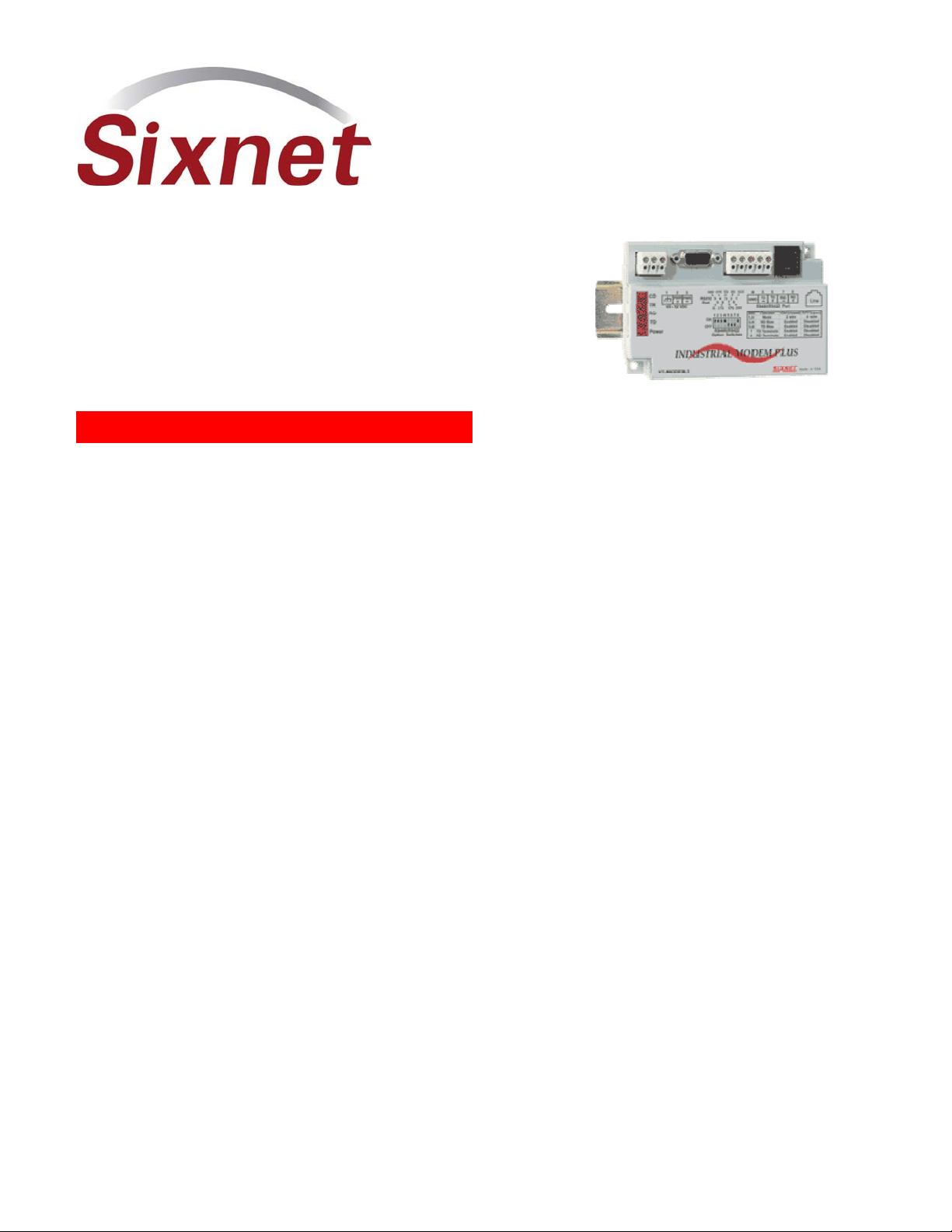
VT-MODEM
Industrial Modems
Installation & Maintenance
Contents at a Glance:
Section 1
Section 2
Section 3
Section 4
Section 5
Section 6
Section 7
Section 8
Section 9
Overview
Performance Specifications
VT-MODEM Mounting
Electrical Connections
Modem Configuration
AT Command Summary
S-Register Summary
Maintenance Information
Product Support & Other Documents
2
5
6
7
14
18
21
23
24
This manual applies to the following products:
General purpose industrial modem (VT-MODEM-1##)
Self-dialing industrial modem (VT-MODEM-2##)
RS485 industrial modem (VT-MODEM-3##)
VT-MODEM User Manual Page 1 of 30 Last Revised: 17-Aug-09
Sixnet Technology Park 331 Ushers Road Clifton Park, NY 12065 USA +1 (518) 877-5173 [email protected]
Page 2
Section 1 Overview
The Sixnet VT-MODEMs are rugged industrial telephone modems that have been designed for operation in
electrical enclosures installed in harsh environments. Each VT-MODEM supports all standard Hayes AT
commands, Fax Class 1 and Class 2 commands and S-registers and therefore can be set-up as an external
modem on any PC. The VT-MODEMs are compatible with any telecommunications or dial-up networking
software.
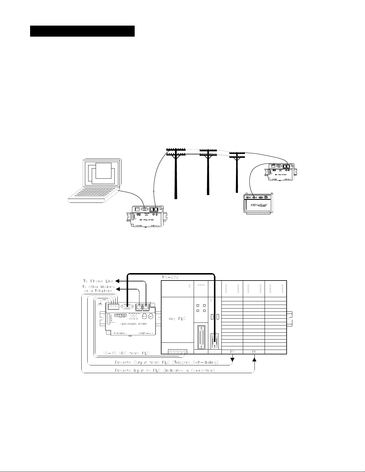
A VT-MODEM allows easy access to PLCs, Sixnet I/O and other devices via dial-in telephone connections.
The modem may be DIN rail or panel mounted for convenient and easy installation adjacent to other DIN
rail components inside of new or existing enclosures. Most Windows software can communicate through a
VT-MODEM to remote devices to perform file transfers, diagnostics, program debugging and many other
operations.
All Sixnet Industrial Modems allow communication to remote sites for data retrieval or diagnostics.
Note: All VT-MODEM models communicate over analog phone lines only.
The Sixnet PLC Self-Dialing Modem (VT-MODEM-2) has all the features of the Sixnet Industrial Modem
(VT-MODEM-1), plus the ability to dial out based on an alarm contact or PLC discrete output.
VT-MODEM User Manual Page 2 of 30 Last Revised: 17-Aug-09
Sixnet Technology Park 331 Ushers Road Clifton Park, NY 12065 USA +1 (518) 877-5173 [email protected]
Page 3
Identifying the modem you have
This section will show how to identify what revision of modem you have.
1. The Sixnet VT-MODEM Wizard will detect the version of the modem you have. Open the wizard
and detect the modem you are connected to by selecting the COM port your modem is connected to
and clicking the red Detect Modem button on most configuration screens. The firmware version of
your modem is indicated as Rev 1, Rev 2 or Rev 3, otherwise the difference is seamless to the typical
Wizard user.
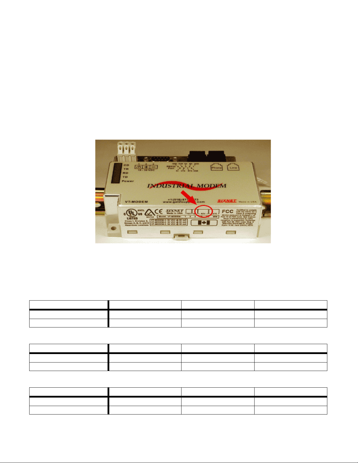
2. On the back of the modem there is a white sticker called the back label that indicates among other
things the revision number (Rev) and modem models. Please see the tables below to see how to
interpret this number.
3. You can also detect the modem type using HyperTerminal. To query the firmware version enter
ati3<enter>. Please see the tables below for information on how to interpret this firmware rev
number.
VT-MODEM-1
VT-MODEM Wizard Rev 1 Rev 2 Rev 3
Back Label 1.00-1.08, 1.10-2.02 1.09 3.00 and above
HyperTerminal (ati3) V2.100-V34_2M_DLS P2109-V90 CX81802-V34
VT-MODEM-2
VT-MODEM Wizard Rev 1 Rev 2 Rev 3
Back Label 1.00-1.04, 1.06-1.08 1.04/1.05 2.00
HyperTerminal (ati3) V2.100-V34_2M_DLS P2109-V90 CX81802-V34
VT-MODEM-3
VT-MODEM Wizard Rev 1 Rev 2 Rev 3
Back Label 1.00-1.02, 1.04-1.06 1.02/1.03 2.00
HyperTerminal (ati3) V2.100-V34_2M_DLS P2109-V90 CX81802-V34
VT-MODEM User Manual Page 3 of 30 Last Revised: 17-Aug-09
Sixnet Technology Park 331 Ushers Road Clifton Park, NY 12065 USA +1 (518) 877-5173 [email protected]
Page 4

VT-MODEM-2 Self-Dialing Feature
The Self-Dialing Modem is triggered by a switch closure or PLC output signal. It dials a pre-stored phone
number and optionally identifies itself by way of a pre-stored ASCII message. Flexible features allow this
modem to perform retries or even connect to alternate number until it has verified that a connection has been
established. The call will terminate when either:
The computer completes its polling and hangs up
The modem discrete input is turned off
A telephone line problem disrupts the call.
The VT-MODEM-2 enables field installed equipment to establish a telephone link based upon a simple
switch closure. This self-dialing modem adds “dial upon alarm” intelligence to any remote site. This
enhanced modem is ideal for:
DIALING UPON ALARM FROM ANY PLC
This m
odem establishes a connection based upon a coil output from any PLC. Once a connection has
been established, the PLC’s system (programming) port is connected to the computer at the other end
of the phone link and may be polled by that computer as if the computer had initiated the call. When
the modem connects to the central computer, it identifies itself so the computer can run the
appropriate I/O driver and interrogate the PLC.
SENDING A MESSAGE BASED UPON A SWITCH CONTACT Locations that do not have PLCs (or other intelligence) can originate calls to alert you to low tank
levels, over tem
perature conditions, or other alarms. Simply connect the appropriate alarm contact to
the modem’s input. The modem will dial the pre-stored phone number and deliver the ID message to
the computer at the receiving end.
VT-MODEM-3 RS485 Port
The VT-MODEM-3 Industrial Modem Plus has an RS422 / RS485 port that can function in place of its
RS232 port. The RS422 / RS485 port supports RS422 and RS485 full duplex and two wire RS485 half
duplex communication to compatible devices. The VT-MODEM-3 is user-configurable to communicate
through either the RS232 port (VT-MODEM-1 mode) or through the RS422 / RS485 port. Only one port can
be used at a time.
VT-MODEM SETUP WIZARD
odem setup utility is provided on the Sixnet CD to help you quickly configure any Sixnet Industrial
A m
Modem. In most applications, no knowledge of modem AT commands or S register contents is necessary.
Pre-configured profiles, for common situations are provided for your convenience. An extensive online help
file is provided with this utility.
VT-MODEM User Manual Page 4 of 30 Last Revised: 17-Aug-09
Sixnet Technology Park 331 Ushers Road Clifton Park, NY 12065 USA +1 (518) 877-5173 [email protected]
Page 5
Section 2 Performance Specifications
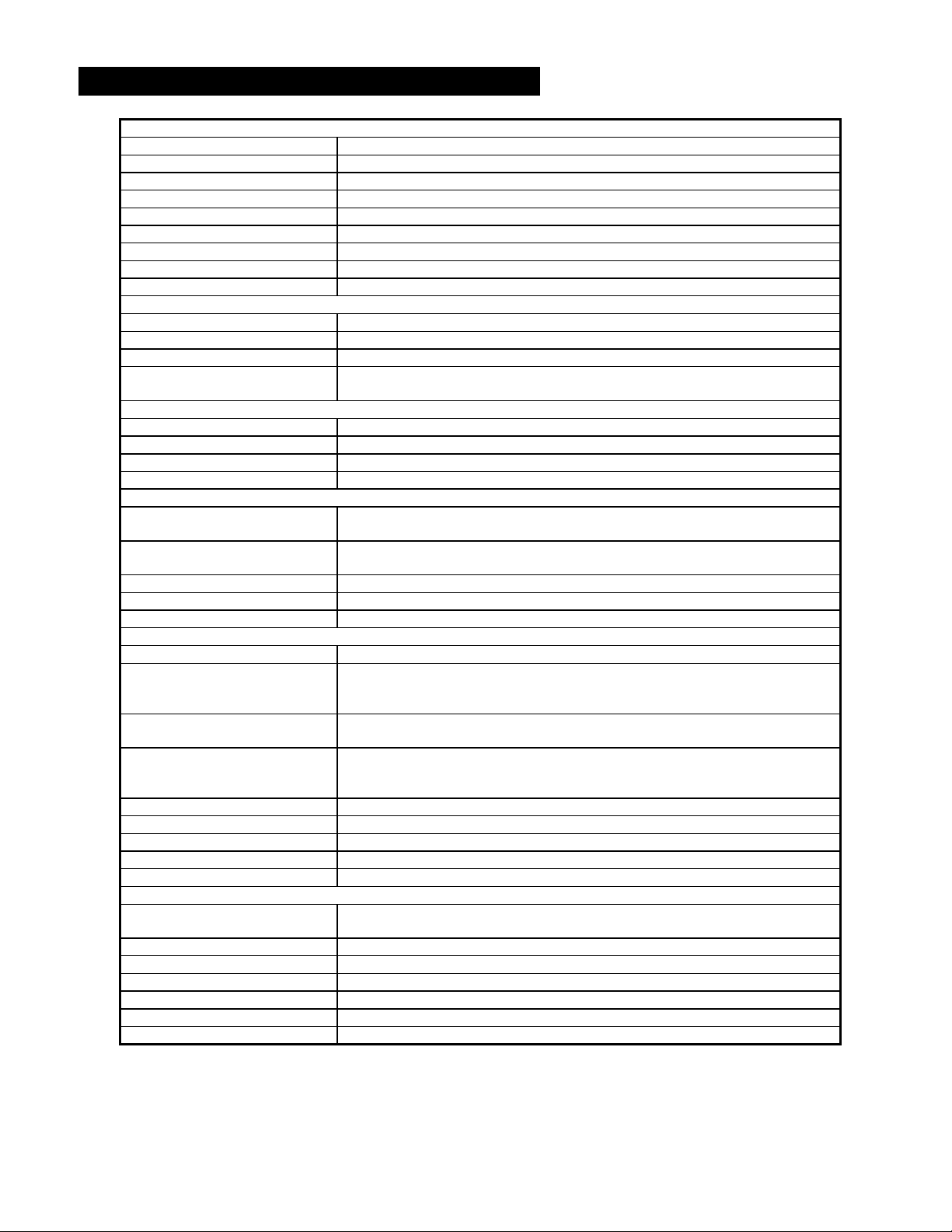
Telephone Line (All models)
Max. Data Rate 33.6 kbps (V.34)
Compatibility V.34, V.32bis, V.32, V.22bis, V.22A/B, V.23, V.21, Bell212A & 103
Data Compression V.44/V.42bis/MNP 5
Error Correction V.42/MNP 2-4
Max Fax Modem Rate 14.4 kbps (V.33)
Fax Modem Compatibility Group 3 (V.33, V.17, V.29, V.27ter, V.21 ch. 2)
Ringer Equivalent 0.3
Line Jack RJ11
Phone Jack RJ11 (VT-MODEM-1 and –2)
RS232 Port (All models)
Max. RS232 Rate 115.2 kbps (Kilobaud)
RS232 Signal Support TXD, RXD, CTS, RTS, DCD, DTR, DSR, RI, GND
RS232 Connector DB9 female, RS232
Command Set All standard AT and S register commands including Class 1, Class 2 Fax commands
and Voice commands
RS422 / RS485 Port (VT-MODEM-3 only)
RS422 mode 4 wire full duplex
RS485 modes 2 or 4 wire party-line operation (half duplex)
Signal rate Standard rates up to 115.2 kbps (Kilobaud)
RS422 / RS485 distance Up to 0.5 miles
Status LEDs (All models)
CD (Carrier detect) The modem has detected a carrier on the phone line (a remote modem has been
detected).
TR (Data Terminal Ready) The PC (or Gateway/VersaTRAK) has established a connection to the modem and is
ready.
RD (Receive Data) Flashes as data is received from the phone line.
TD (Transmit Data) Flashes as data is sent out the phone line.
Power On when power is present.
General Characteristics (All models)
Input Power 10 - 30 VDC (VT-MODEM-1, –2), 10 – 52 VDC (VT-MODEM-3)
Input Current (Rev 1 and Rev2, see
section 1)
Input Current (Rev 3) 50mA @ 24VDC and 30mA in Low Power mode for -1 and -2 (typical)
Certification FCC Part 15 and FCC Part 68; UL 508; CSA C22.2/14;
Operating Temperature -30 ° to 70 ° C
Storage Temperature -40 ° to 85 ° C
Humidity 5 to 95% RH (non-condensing)
Mounting DIN rail or panel mount
Dimensions W x 4.75L x 1.35H inches (8.2 W x 12.1 L x 3.4H cm)
PLC Discrete I/O Interface (VT-MODEM-2 only)
Trigger Input (From PLC) Connects to PLC output. Starts auto-dialing upon transition from OFF to ON. Modem
Voltage Range 9 to 30 VDC
Input Current 6.5 mA at 24 VDC
Max. OFF Voltage 5 VDC
On-line Output (To PLC) Output is ON as long as a connection exists (carrier detect).
Output Characteristics Sourcing – switches supply power
Max. Output Current 100 mA
65mA @ 24VDC and 26mA in Low Power mode of –1 (typical)
97mA @ 24VDC and 64mA in Low Power mode of –2 (typical)
68mA @ 24VDC and 28mA in Low Power mode of –3 (typical)
55mA @ 24VDC and 35mA in Low Power mode for -3 (typical)
ACA TS 001- 1997; ACA TS 002-1997; AS/NZS3260-1993;
AS/NZS3548-1995; CTR21 (98/482/EC); EN55022; IEC 950:1991.
will stay connected while input is ON.
VT-MODEM User Manual Page 5 of 30 Last Revised: 17-Aug-09
Sixnet Technology Park 331 Ushers Road Clifton Park, NY 12065 USA +1 (518) 877-5173 [email protected]
Page 6
Section 3 VT-MODEM Mounting
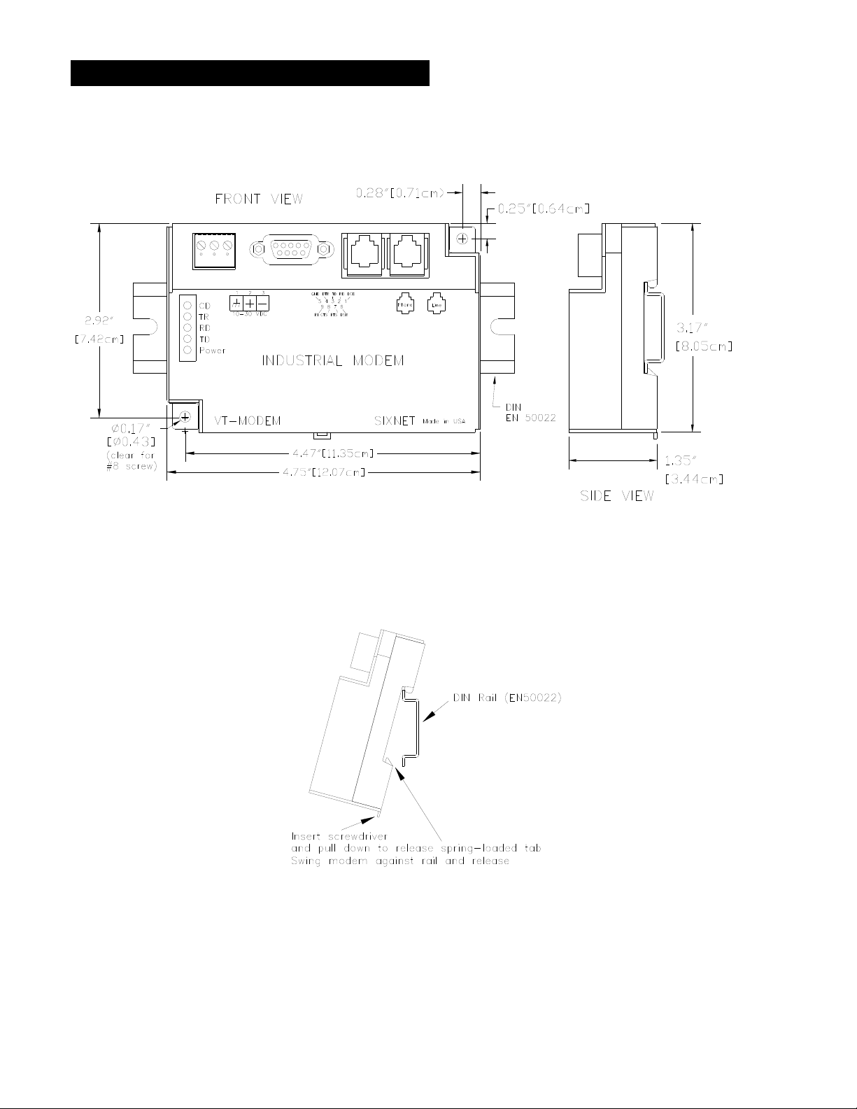
The VT-MODEM snaps onto standard DIN rail (DIN EN 50022) or is mounted to a flat panel using #6 or #8
screws. See Figure 3-1. The modem can be installed in any orientation, directly adjacent to other DIN rail
components or in any convenient location within the enclosure. The modem should be installed within 6 feet
of the device it will be connected to.
Figure 3-1: VT-MODEM DIMENSIONS, ALL MODELS
For DIN rail mounting, hook the top, rear of the modem onto the top edge of the DIN rail. Using a small flat
head screwdriver, pull down on the spring-loaded tab on the bottom of the modem and push the modem back
against the rail. Reverse these steps to remove the modem. See Figure 3-2 below.
Figure 3-2: DIN RAIL MOUNTING
VT-MODEM User Manual Page 6 of 30 Last Revised: 17-Aug-09
Sixnet Technology Park 331 Ushers Road Clifton Park, NY 12065 USA +1 (518) 877-5173 [email protected]
Page 7
Section 4 Electrical Connections
RS232 Connections (All VT-MODEM Models):
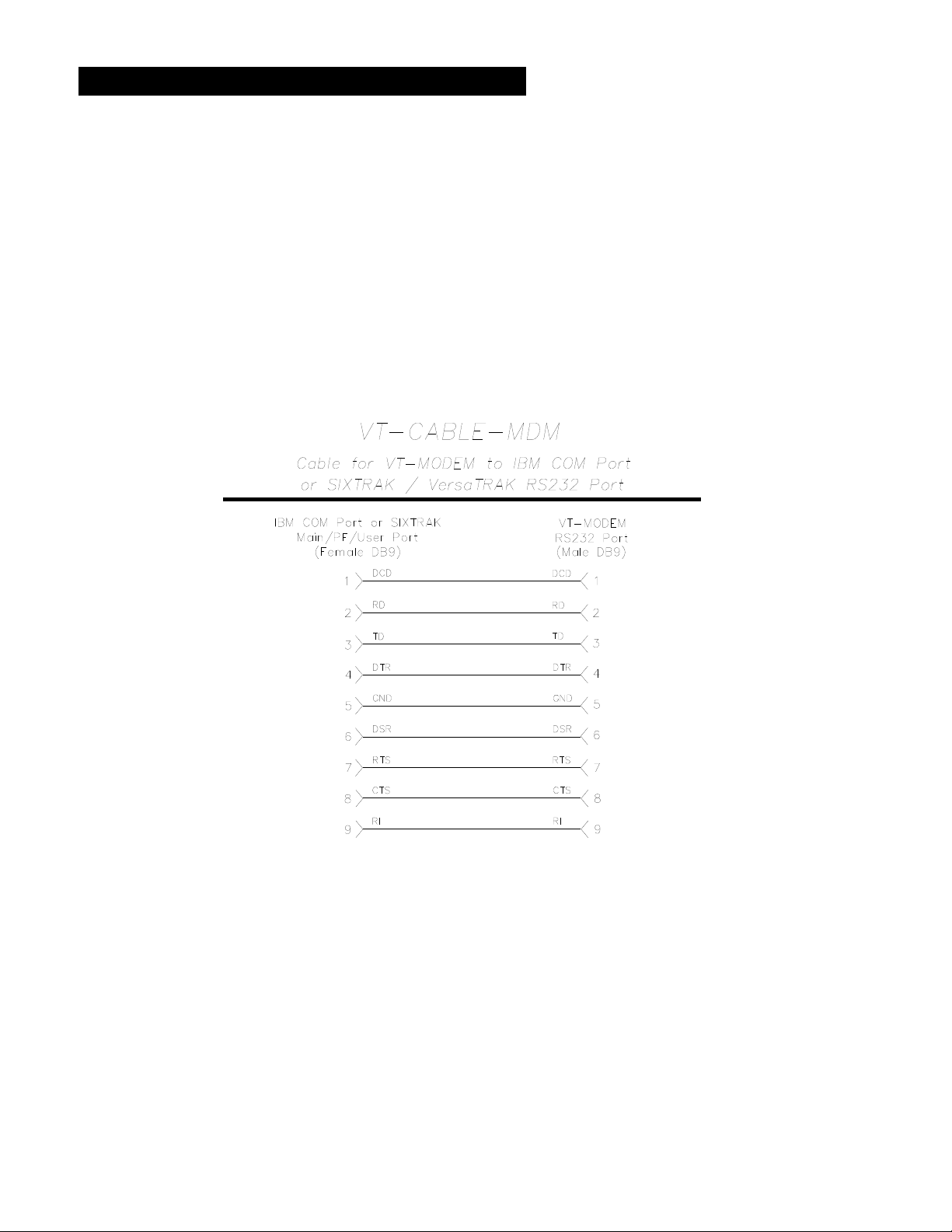
Use the Sixnet RS232 cable (VT-CABLE-MDM, which is 6 feet in length) or an equivalent cable to connect
the modem's RS232 port (DB9 Male cable end) to the RS232 port on a SIXTRAK Gateway, VersaTRAK
RTU or PC (DB9 Female cable end). As shown in Figure 4-1, the VT-CABLE-MDM is a straight through
serial communications cable suitable for connecting a DTE device (PC, Gateway or VersaTRAK) to a DCE
device (VT-MODEM). For IPm and ST-GT-1210 stations, use a straight-through Ethernet cable (not
supplied) and the RJ45 to DB9 male adapter that came with the station.
Cable requirements for PLCs and other devices may be different. Refer to the PLC or other device’s
documentation for cable pinouts. Some PLC cables are documented in the Technical notes provided on the
Sixnet CD that came with your modem.
Figure 4-1: VT-CABLE-MDM Wiring
VT-MODEM User Manual Page 7 of 30 Last Revised: 17-Aug-09
Sixnet Technology Park 331 Ushers Road Clifton Park, NY 12065 USA +1 (518) 877-5173 [email protected]
Page 8
VT-MODEM-1 Power, Phone Line Connections:
DC Power Wiring
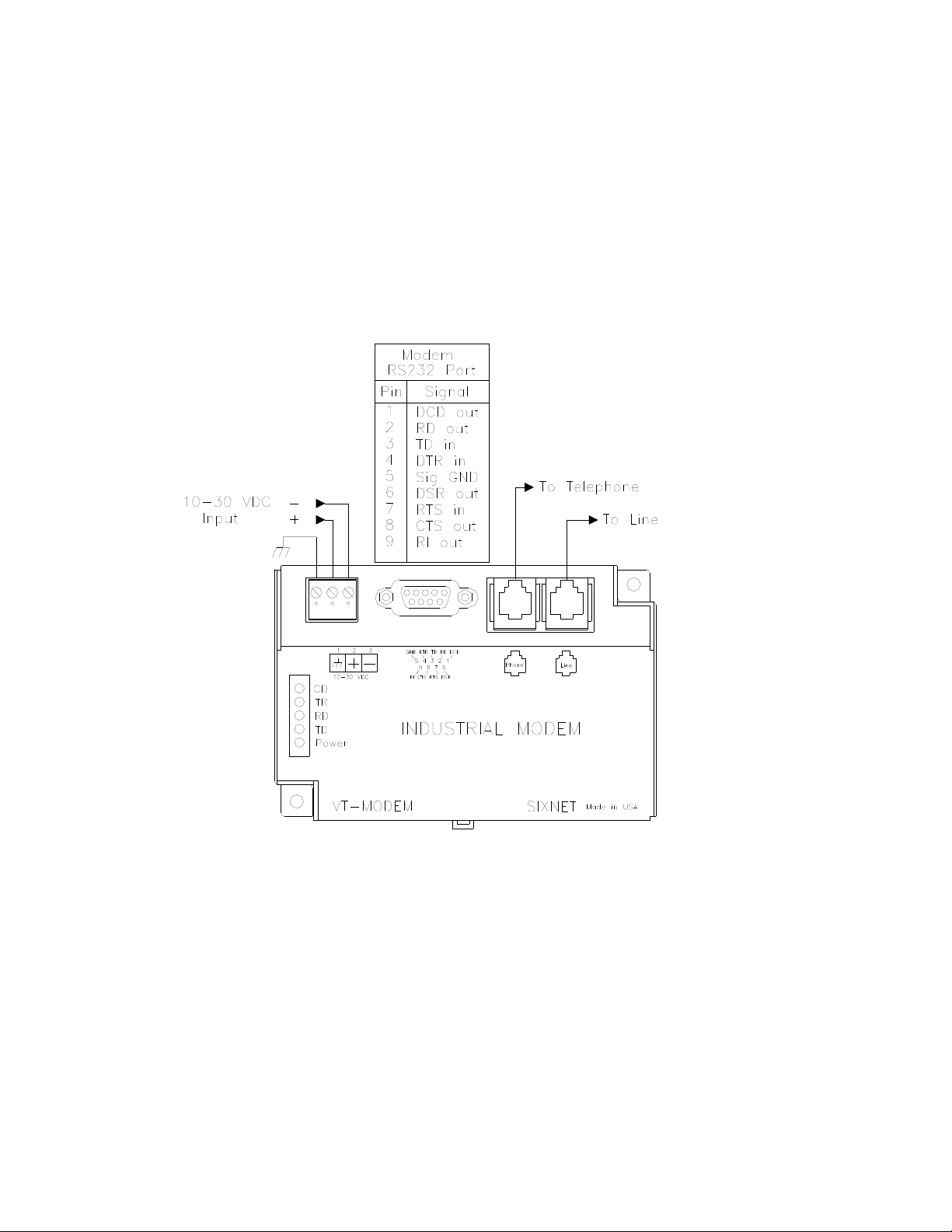
Connect 10 - 30 VDC to the VT-MODEM-1 as shown in Figure 4-2. The modem can usually be powered
from the same DC source as other devices in the enclosure. All the screw terminals should be tightened to a
maximum of 3.48 in-lbs.
Telephone Cable
Connect analog phone lines to the RJ-11 jacks as appropriate. One RJ-11 jack is provided to connect directly
to a telephone (optional) and the second RJ-11 jack functions as the connection to the telephone network.
Figure 4-2: VT-MODEM-1 WIRING
VT-MODEM User Manual Page 8 of 30 Last Revised: 17-Aug-09
Sixnet Technology Park 331 Ushers Road Clifton Park, NY 12065 USA +1 (518) 877-5173 [email protected]
Page 9
VT-MODEM-2 Power, Phone Line, Self-Dial Connections:
DC Power Wiring
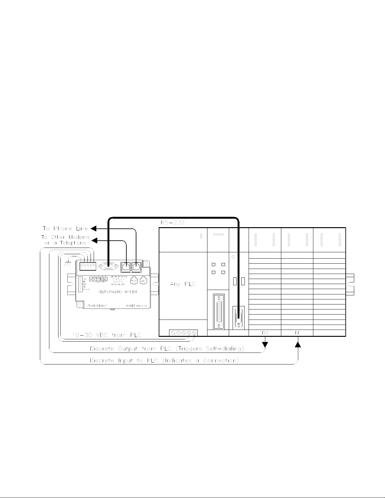
Connect 10 - 30 VDC to the VT-MODEM-2 as shown in Figure 4-3. The modem can usually be powered
from the same source as other devices in the enclosure. All the screw terminals should be tightened to a
maximum of 3.48 in-lbs.
Telephone Cable
Connect analog phone lines to the RJ11 jacks as appropriate. One RJ-11 jack is provided to connect directly
to a telephone (optional) and the second RJ-11 jack functions as the connection to the telephone network.
PLC Self-Dial I/O Connections
Connect a 10-30VDC signal to the ‘From PLC’ (trigger input) terminal. An OFF to ON transition of this
signal starts the auto-dialing sequence. The modem will call and remain connected while the signal is ON.
When the signal goes false, the modem will terminate the connection or the call in progress.
The ‘To PLC’ (on-line output) terminal will go ON (ON = user supplied VDC input) when a modem to
modem connection has been established and the proper ‘Acknowledge Message’ has been received.
Figure 4-3: VT-MODEM-2 WIRING
VT-MODEM User Manual Page 9 of 30 Last Revised: 17-Aug-09
Sixnet Technology Park 331 Ushers Road Clifton Park, NY 12065 USA +1 (518) 877-5173 [email protected]
Page 10
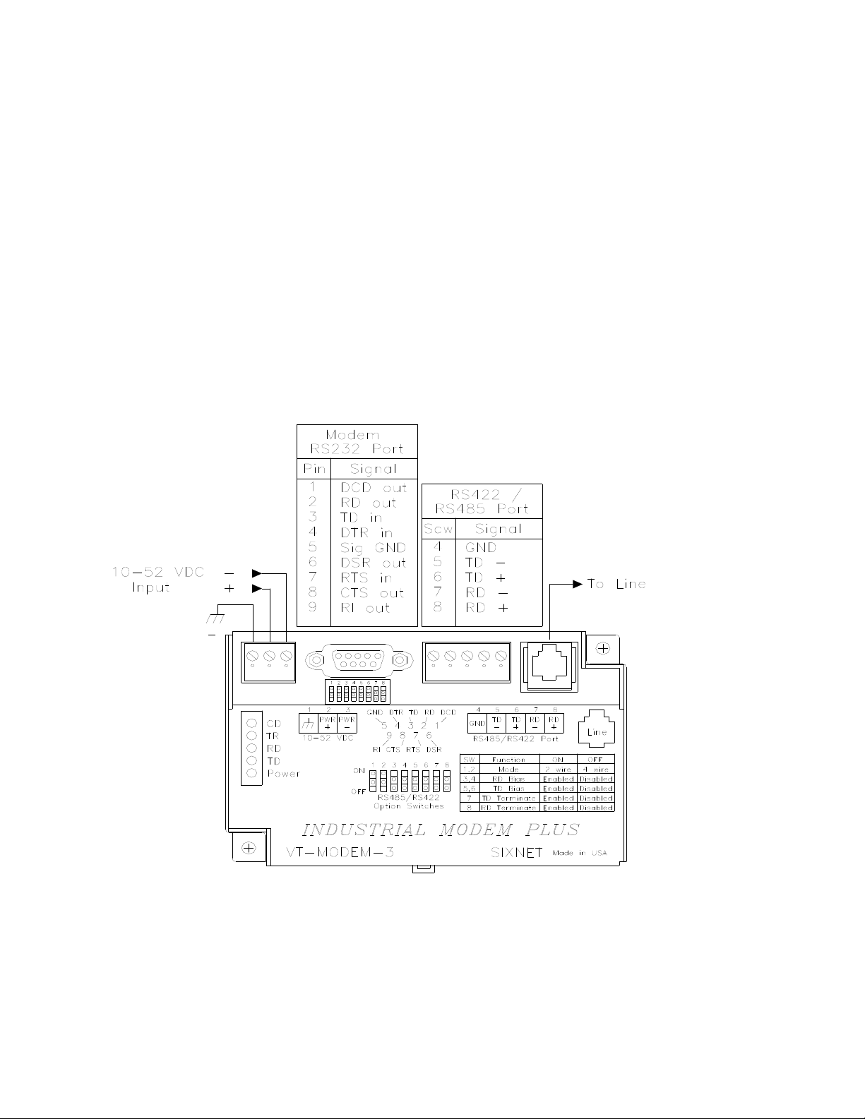
VT-MODEM-3 Power, Phone Line, RS422 / RS485 Connections:
DC Power Wiring
Connect 10 - 52 VDC to the VT-MODEM-3 as shown in Figure 4-4. The modem can usually be powered
from the same source as other devices in the enclosure. All the screw terminals should be tightened to a
maximum of 3.48 in-lbs.
Telephone Cable
Connect an analog phone line to the RJ-11 jack as appropriate.
RS422 / RS485 Cabling and DIP Switch Settings
Refer to Figure 4-4 for typical wiring configurations. Fabricate a cable to connect the modem's RS422 /
RS485 port to the field device(s).
The VT-MODEM-3 has DIP switches. These switches establish the mode of operation for the RS422/RS485
port. Set these switches to match the type of wiring connected to the RS422/RS485 port. Refer to Figure 4-5
on the next page. It is not necessary to cycle power to the modem if DIP switch changes are made.
Figure 4-4: Typical RS422 / RS485 Wiring
VT-MODEM User Manual Page 10 of 30 Last Revised: 17-Aug-09
Sixnet Technology Park 331 Ushers Road Clifton Park, NY 12065 USA +1 (518) 877-5173 [email protected]
Page 11
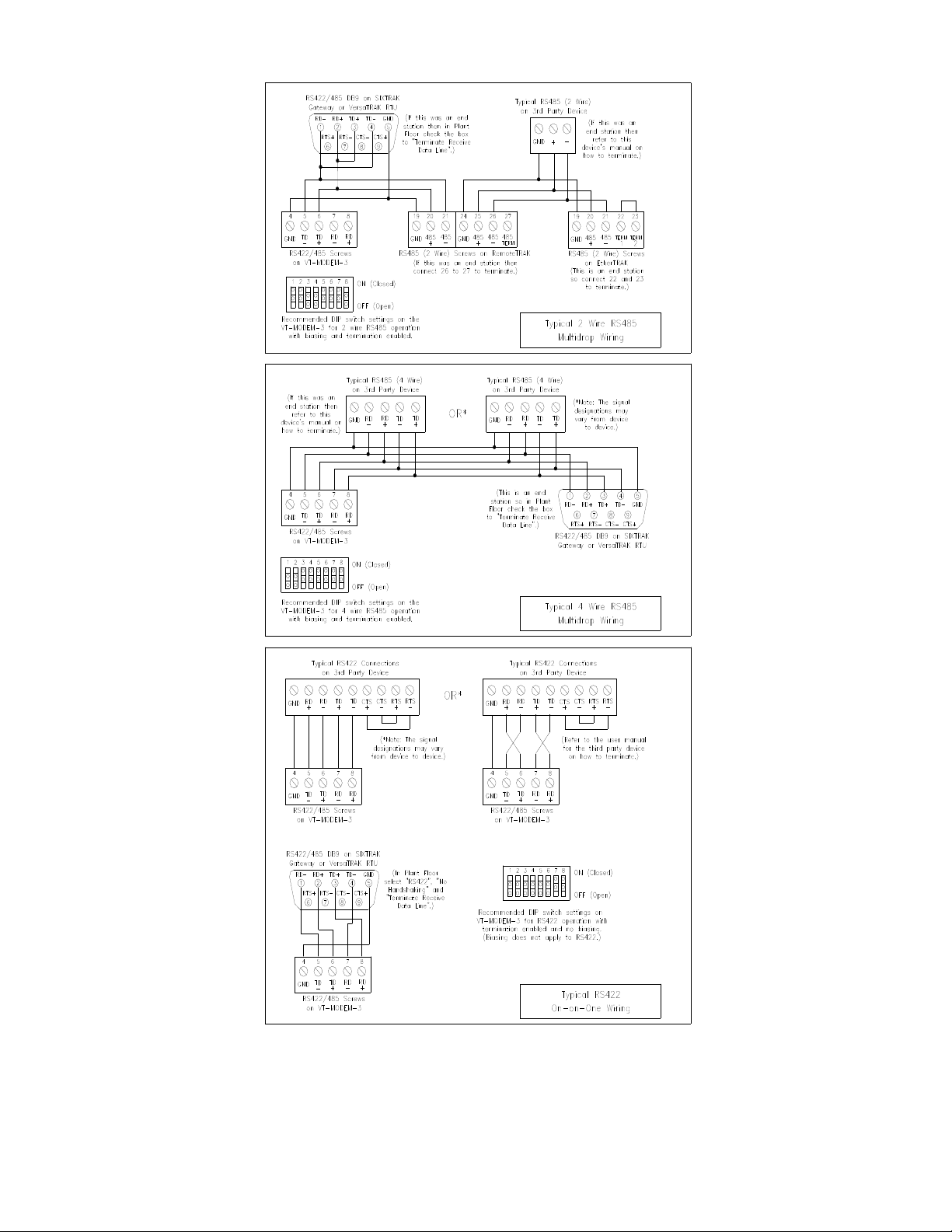
Figure 4-5: Detailed RS422 / RS485 Wiring and DIP Switch Settings
VT-MODEM User Manual Page 11 of 30 Last Revised: 17-Aug-09
Sixnet Technology Park 331 Ushers Road Clifton Park, NY 12065 USA +1 (518) 877-5173 [email protected]
Page 12

VT-MODEM-3 DIP Switch Summary
2 wire RS485 Cabling
Receive Bias Enabled (RS485 4 wire Cabling)
Transmit Bias Enabled (RS485 2 and 4 wire Cabling)
7 ON, 8 OFF = 2 wire Termination Enabled
7 ON, 8 ON = 4 wire Termination Enabled
7 ON, 8 OFF = 2 wire Termination Enabled
2 and 4 wire Termination Disabled
Transmit Bias Disabled (RS485 2 and 4 wire Cabling)
Receive Bias Disabled (RS485 4 wire Cabling)
RS422 or 4 wire RS485 Cabling
RS422 / RS485 Network Termination
The VT-MODEM-3 has built-in termination components for the Receive Data and Transmit Data signals.
Termination of these signals is enabled by setting DIP switches on the VT-MODEM-3. Termination
components are often built into other RS422 / RS485 devices, and are typically enabled by setting a jumper
or DIP switch on the appropriate device.
Here are some guidelines for the use of termination:
Terminations should be enabled at both ends of an RS422 communication cable.
Terminations should be enabled at both end stations on an RS485 network. No more than two stations
should be terminated on an RS485 network.
Bias Resistors (RS485 networks only)
On an RS485 two wire network there should be one pair of bias resistors acting upon the transmit/receive
wires. On an RS485 four wire network there should be two pairs of bias resistors; one pair on the receive
wires and one pair on the transmit wires. Bias resistors force the receive or transmit/receive wires to a known
(non-floating) state when none of the RS485 devices are transmitting data. If bias resistors are not present,
some RS485 devices may experience communication errors due to noise on the floating wires. Bias resistors
do not apply to RS422 wiring because the wires are always driven by the two RS422 devices. The wires are
not permitted to float.
The location of the bias resistors is not critical. Typically they are installed at the master RS485 device. Bias
resistors are provided in the VT-MODEM-3 and are enabled through DIP switch settings. There should be
only one pair of these resistors connected to an RS485 two wire network, and only two pairs of these
resistors connected to an RS485 four wire network. Refer to Figure 4-5 for recommended VT-MODEM-3
DIP switch settings. Do not enable the VT-MODEM-3 bias resistors if there are bias resistors enabled on one
of the other RS485 devices.
VT-MODEM User Manual Page 12 of 30 Last Revised: 17-Aug-09
Sixnet Technology Park 331 Ushers Road Clifton Park, NY 12065 USA +1 (518) 877-5173 [email protected]
Page 13
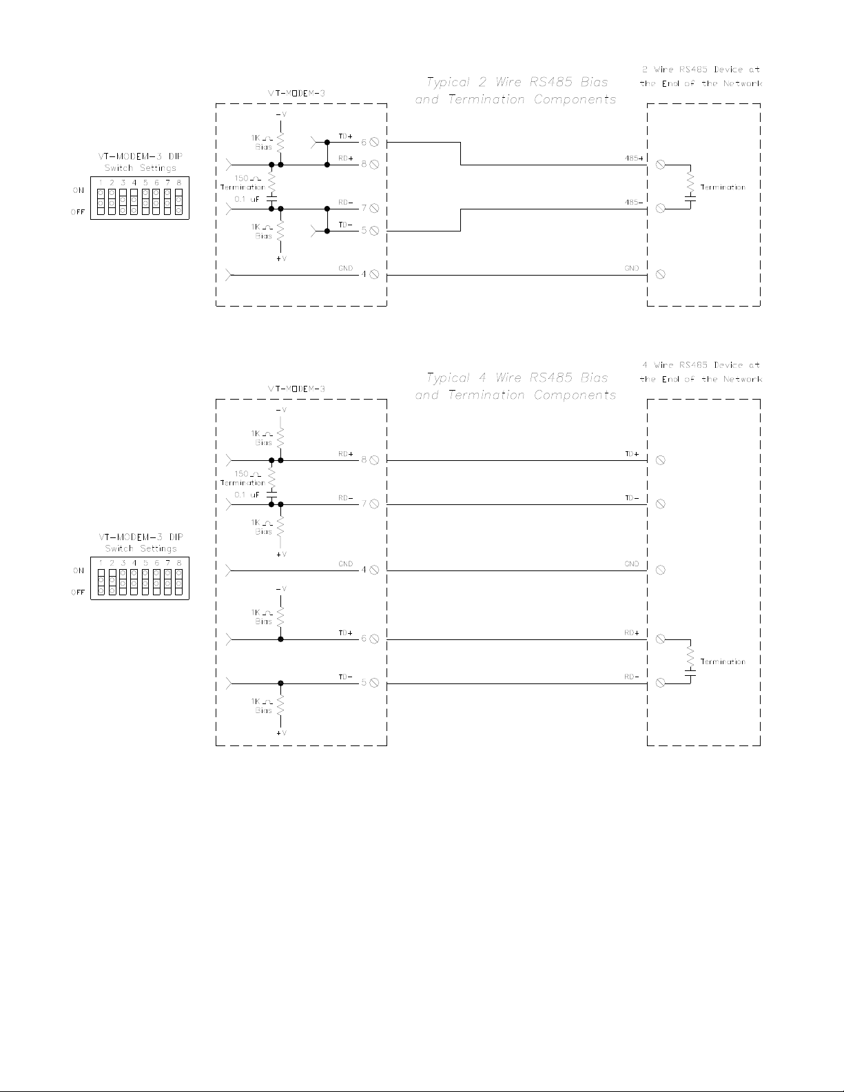
Typical RS485 Network Bias and Termination
Configuring a PC Modem to Communicate with a VT-MODEM-3 in RS422 or RS485 Mode:
It may be necessary to change your PC’s modem settings when communicating with a VT-MODEM-3
running in RS422 or RS485 mode. The PC modem, VT-MODEM-3 and the modem-to-modem speed should
all be set to the same rate.
VT-MODEM User Manual Page 13 of 30 Last Revised: 17-Aug-09
Sixnet Technology Park 331 Ushers Road Clifton Park, NY 12065 USA +1 (518) 877-5173 [email protected]
Page 14

Section 5 Modem Configuration
Configuring a VT-MODEM for use with Sixnet I/O:
All VT-MODEM models are factory configured to use the default communication settings for SIXTRAK
Gateways and VersaTRAK RTUs. If a VT-MODEM is connected to a PLC, PC or other non-Sixnet device,
then it may be necessary to reconfigure the modem. See the upcoming sections for further details.
AT Command String at Powerup
Upon powerup, a SIXTRAK gateway or VersaTRAK RTU can send a command string to a VT-MODEM.
This capability can be used to assure that the modem is set to a particular mode of operation, such as auto
answer mode. Refer to the “Set Modem String” topic in the Plant Floor program’s online help for
information on this capability. Any standard AT command can be sent by the gateway or RTU.
Configuring a VT-MODEM as an External Modem on a PC:
The VT-MODEM can be connected directly to a PC. The modem will need to be “installed” in Windows
prior to use. Here are instructions to install the modem in both Windows 95, 98 and Windows NT.
Modem Installation in Windows 95/98
Plug and Play method (recommended):
1) With the PC off, connect DC power and the telephone line to the VT-MODEM. Connect a
communications cable (VT-CABLE-MDM or equivalent) between the VT-MODEM and the PC. Turn
on the PC. During the boot-up process, Windows should detect the modem and display the New
Hardware Found dialog box.
2) Make the selection “Select from a list of alternative drivers”.
3) The Select Device dialog will be displayed. In the column labeled Manufacturers, select “Standard
Modem Types”. In the column labeled Models, select “Standard 28800 bps Modem”. Click OK.
Windows will then complete the boot-up process. (The standard Windows driver is used for the VTModem. Although the VT-Modem supports baud rates to 33,600 bps, the selections in Windows are
limited to 28800 bps.)
4) To verify that the modem has been installed, select Start Settings Control Panel, and then double
click the Modems icon. The modem should be listed as “Standard 28800 bps Modem”.
Here is an alternate modem installation procedure (use if the PC is already powered up):
1) Connect the DC power, communications cable (VT-CABLE-MDM or equivalent) and telephone line as
described above.
2) Select Start Settings Control Panel, and then double click the Modems icon.
3) The Install New Modem dialog box will appear. Do not select the “Don’t detect my modem, I will select
it from a list”. Instead, click Next and allow Windows to search the com ports and detect the modem.
4) Windows should find a modem called Standard Modem. Click Next and Windows will complete
installation of the Standard Modem. (Alternately, click Change and select “Standard Modem Types”
from the Manufacturers list, and “Standard 28800 bps Modem” from the Models list.)
VT-MODEM User Manual Page 14 of 30 Last Revised: 17-Aug-09
Sixnet Technology Park 331 Ushers Road Clifton Park, NY 12065 USA +1 (518) 877-5173 [email protected]
Page 15

5) To verify that the modem has been installed, select Start Settings Control Panel, and then double
click the Modems icon. The modem should be listed as either a “Standard Modem” or a “Standard
28800 bps Modem” depending on the steps followed above.
6) Upon re-booting the machine, Windows may still find the VT-MODEM as new hardware. If this
happens, select “Do not install a driver (Windows will not prompt again)”.
Modem Installation in Windows NT
1) Select Start Settings Control Panel, and then double click the Modems icon.
2) The Install New Modem dialog box will appear. Do not select the “Don’t detect my modem, I will select
it from a list”. Instead, click Next and allow Windows to search the com ports and detect the modem.
3) Windows should find a modem called Standard Modem. Click Next and Windows will complete
installation of the Standard Modem. (Alternately, click Change and select “Standard Modem Types”
from the Manufacturers list, and “Standard 28800 bps Modem” from the Models list.)
4) To verify that the modem has been installed, select Start Settings Control Panel, and then double
click the Modems icon. The modem should be listed as either a “Standard Modem” or a “Standard
28800 bps Modem” depending on the steps followed above.
Modem Installation in Windows XP
1) Select Start Settings Control Panel, and then double-click the Phone and Modems Options icon.
2) Go to the Modems tab and click the Add button to install a new modem. The Install New Modem wizard
will appear. Select the “Don’t detect my modem, I will select it from a list”.
3) Highlight the manufacturers list “Standard Modem Types”. From the models list select “Standard 28800
bps Modem”, then click Next.
4) Select the COM Port on your computer the modem will be connected to.
5) To verify that the modem has been installed, select Start Settings Control Panel, and then double
click the Phone and Modem Options icon. Go to the Modems tab. The modem should be listed as a
“Standard 28800 bps Modem” connected to COM port you selected.
Once the VT-MODEM modem has been added to your Windows 95, 98, NT or XP system, it is ready for
use.
If you are using Sixnet I/O, you can use the Sixnet Sixdial software to dial out and establish a connection
with your Sixnet I/O. The Sixdial utility allows other Sixnet programs to perform operations such as data
transfers, hardware configuration and diagnostics, and ISaGRAF programming. (Refer to the on-line help in
the Sixdial utility for more information on these software tools).
If you are using a PLC or other device, refer to the documentation for that device as necessary.
To Remove a Modem
If it ever becomes necessary to re-install the modem for any reason, select Start Settings Control Panel,
and then double click the System icon. Next, click the Device Manager tab. The list should display a
Modems icon. Double click the Modems icon. Highlight the modem to be removed and then click the
Remove button. To reinstall the modem, follow the installation steps as previously described.
VT-MODEM User Manual Page 15 of 30 Last Revised: 17-Aug-09
Sixnet Technology Park 331 Ushers Road Clifton Park, NY 12065 USA +1 (518) 877-5173 [email protected]
Page 16
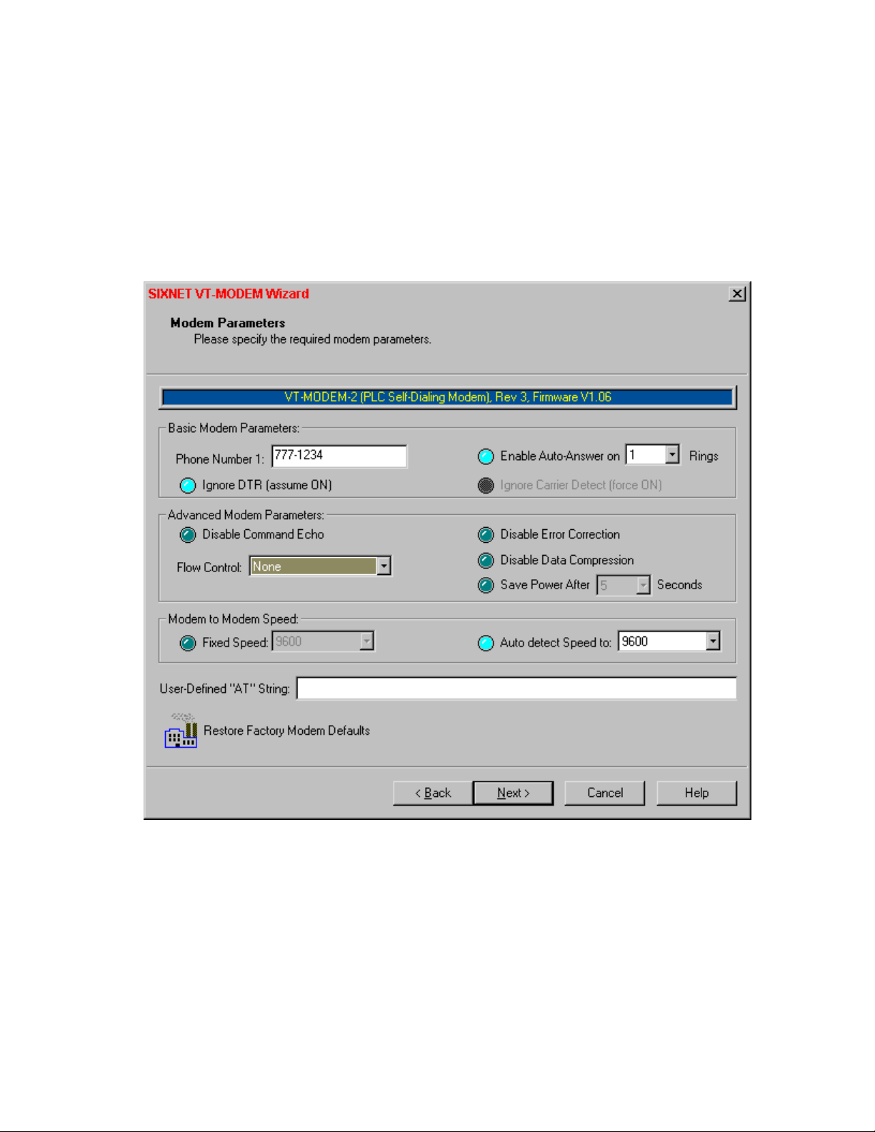
Configuring a VT-MODEM Using the VT-MODEM Setup Wizard:
It is highly recommended that the Sixnet VT-MODEM Setup Wizard be used for VT-MODEM
configuration. Simply check the appropriate boxes, choose the appropriate communication settings from the
dropdown lists, and load the configuration into the VT-MODEM. This utility does not require user
knowledge of AT commands and S-registers.
Refer to the online help system in the VT-MODEM Setup Wizard for instructions and application notes.
Note: The VT-MODEM Setup Wizard must be used to configure the self dial parameters of the VTMODEM-2 and the RS422 / RS485 port parameters of the VT-MODEM-3.
Setting the Modem's Baud Rate for the PLC
The VT-MODEM has an automatic baud rate detection feature that lets the modem recognize commands through its
serial port at any supported baud rate. However, if the modem is connected to a device that does not send commands or
data unless spoken to (such as most PLCs), then the modem will pass information from the phone line to its serial port
at the last auto-detected baud rate. This is typically the baud rate used by the VT-MODEM setup Wizard when
configuring the modem.
The VT-MODEM is defaulted at the factory for 9600-baud. To change this setting, connect the modem to a PC. Start
the VT-MODEM setup Wizard and choose the baud rate that matches the PLC’s baud rate. Then choose the
appropriate settings and write the configuration to the modem. Exit the VT-MODEM setup Wizard and reconnect the
modem to the PLC. (Be sure to cycle power to the modem.) Call the modem and verify that the PLC is responding to
commands.
VT-MODEM User Manual Page 16 of 30 Last Revised: 17-Aug-09
Sixnet Technology Park 331 Ushers Road Clifton Park, NY 12065 USA +1 (518) 877-5173 [email protected]
Page 17

Limiting the Phone Line Connection Speed for Reliability
Typically, when a modem-to-modem connection is established, the two modems negotiate and connect at the fastest
possible phone line speed that is within the capability of both modems. The quality of the phone line connection
(during the negotiation) will be taken into account. If both modems are of a modern design (such as the VT-MODEM),
the phone line speed can be 33.6K bits per second (or higher, using data compression). Note that this phone line speed
is independent of the DTE (serial port) speed, though some older modems require that the phone line speed and DTE
speed be the same.
In practice the quality of any phone line changes continually, and frequent data errors may occur. The probability of
errors usually increases as the phone line speed increases. Therefore, it is often desirable to restrict the phone line
speed to a rate that will provide good performance and yield reliable data. It is also commonplace to restrict the phone
line speed to maintain compatibility when replacing an older modem with the VT-MODEM.
By default, the VT-MODEM will permit any phone line speed up to 115.2 kbps when data compression is enabled. If
you experience intermittent or unreliable communication, try setting the modem-to-modem speed (in the VT-MODEM
Setup Wizard) to a lower value, to restrict the phone line speed. (Remember to load the new configuration to the
modem.)
VT-MODEM Profile Summary
Here is a summary of the active configuration, user profile 0, user profile 1 and the factory defaults when the
modem is shipped. Each time the modem is powered up, first the factory default settings (as listed in Section
6) are loaded into the active configuration. Next, the designated user stored profile is loaded into the active
configuration. User profile 0 is loaded by default (see the &Y command in Section 6) and it contains all
factory defaults with the exception that it is set to auto answer (register S0=1), and ignore DTR (&D0).
The User profile 1 contains all normal factory defaults (as listed in Section 6).
ACTIVE PROFILE:
B1 E1 L1 M1 N0 Q0 T V1 W0 X4 Y0 &C1 &D0 &G0 &J0 &K3 &Q5 &R1 &S0 &T5 &X0 &Y0
S00:001 S01:000 S02:043 S03:013 S04:010 S05:008 S06:002 S07:050 S08:002 S09:006
S10:014 S11:085 S12:050 S18:000 S25:005 S26:001 S36:007 S38:020 S46:138 S48:007
S95:000
STORED PROFILE 0:
B1 E1 L1 M1 N0 Q0 T V1 W0 X4 Y0 &C1 &D0 &G0 &J0 &K3 &Q5 &R1 &S0 &T5 &X0
S00:001 S02:043 S06:002 S07:050 S08:002 S09:006 S10:014 S11:085 S12:050 S18:000
S36:007 S40:104 S41:195 S46:138 S95:000
STORED PROFILE 1:
B1 E1 L1 M1 N0 Q0 T V1 W0 X4 Y0 &C1 &D2 &G0 &J0 &K3 &Q5 &R1 &S0 &T5 &X0
S00:000 S02:043 S06:002 S07:050 S08:002 S09:006 S10:014 S11:085 S12:050 S18:000
FACTORY DEFAULTS:
B1 E1 L1 M1 N0 Q0 T V1 W0 X4 Y0 &C1 &D2 &G0 &J0 &K3 &Q5 &R1 &S0 &T5 &X0 &Y0
S00:000 S01:000 S02:043 S03:013 S04:010 S05:008 S06:002 S07:050 S08:002 S09:006
S10:014 S11:085 S12:050 S18:000 S25:005 S26:001 S36:007 S38:020 S46:138 S48:007
S95:000
VT-MODEM User Manual Page 17 of 30 Last Revised: 17-Aug-09
Sixnet Technology Park 331 Ushers Road Clifton Park, NY 12065 USA +1 (518) 877-5173 [email protected]
Page 18

Section 6 AT Command Summary
All VT-MODEM models support the AT commands, Fax Class 1 and Class 2 commands listed in this
Section. The VT-MODEM contains a set of factory default settings, which can always be restored by the
user. (See the &F command.) The modem also provides two user profiles (profile 0 and profile 1) which
hold settings as set and saved by the user. (See the &W command.) The settings currently in use by the
modem are generally referred to as the active configuration.
Notes:
VT-MODEM-2 self-dial parameters and VT-MODEM-3 RS422 / RS485 port parameters can only be set using the VTMODEM SETUP Wizard, which is provided on the Sixnet Programmable I/O for Windows CD. Refer to the on-line
help in the VT-MODEM Setup Wizard for more information.
The following tables only list the AT commands supported by the current modem firmware. For a complete
list of AT commands, all valid parameters, and default settings for each AT command please see the Sixnet
online help system of the VT-MODEM Setup Wizard.
Commands marked with an asterisk (*) have different characteristics, depending on the revision of VTMODEM being used. Refer to the online help system of the VT-MODEM Setup Wizard for the details of
these differences.
Command Function
A/ Re-execute Last Command; do not precede with AT command and do not follow with a carriage
return.
A Go off hook and Answer A Call
AT=x Write value x to last selected register.
AT? Report the value of last selected register.
Bn Set data standard to CCITT(Europe et. al.) or Bell Mode(U.S., Canada) for connections at 300 or
1200 bps.
Cn Carrier Control (parameter = 1 only)
Dn Dial (originate a call); typical usage: ATDT5551212 to tone dial number. ATDS=n to dial nth
stored number.
E Echo command to monitor when typed
Fn Not available.
Hn Disconnect (Hang up)
In Identification; reports product code, name, ROM and firmware data, etc.
Ln Speaker Volume (not available)
Mn Speaker Control (not available)
* Nn
On Return To On-line Data Mode
P Set Pulse Dial Default.
Qn Quiet Results Codes Control; when enabled, result codes are reported to the monitor.
Sn Establishes S Register n as the last register accessed
Sn-x Write value x to S Register n.
Sn? Reports the value of S Register n.
T Set Ton e Dial Default
Vn Set Result Code Format to terse or verbose.
Wn Connect Message Control sets the format of the connect messages.
Xn Extended results code
Yn Long space disconnect
Zn Perform Soft Reset and Restore stored user configuration profile 0 or 1.
&Cn RLSD (DCD) Option; set DCD signal to indicate presence of carrier or forces DCD signal on at
&Dn DTR Option; set how modem interprets the DTR signal.
Automode Enable; enabled allows connection at highest possible modem speed, disabled fixes
speed according to register S37.
all times.
VT-MODEM User Manual Page 18 of 30 Last Revised: 17-Aug-09
Sixnet Technology Park 331 Ushers Road Clifton Park, NY 12065 USA +1 (518) 877-5173 [email protected]
Page 19

&Fn Restore factory configuration profile 0 or 1.
&Gn Select guard tone
&Jn Telephone jack control
&Kn Set Flow Control
* &Mn
Asynchronous/synchronous mode selection
&Pn Select pulse dial make/break ratio
* &Qn
Asynchronous/synchronous mode selection
&Rn RTS/CTS option sets how the modem controls the CTS signal
&Sn DSR Override sets how the modem controls the DSR signal
&Tn Test & diagnostic settings
&V Display current configuration, stored user profiles and stored telephone numbers
&V1 Display last connection statistics
&Wn Store current active configuration in one of the two user profiles
&Xn Select synchronous clock source
&Yn Designate a default-reset profile. This profile will be active after a hard reset
* &Zn=x
Store phone number; n = 0 to 3 and x = dial string
%E Enable/disable line quality monitor and autoretrain or fallback/fail forward
%L Report line signal level
%Q Report line signal quality
%7 Plug and Play Serial Number
%8 Plug & Play Vendor ID, Prod. No.
\Kn Break Control sets how the modem responds to a break signal
\Nn Sets the Operating Mode of the modem: direct, normal, reliable or auto reliable
\Vn Single Line Connect Message Enable
\An Select Max MNP Block Size
\Bn Transmit Break to Remote sets the length of break signal sent to remote modem(in non error
correction mode)
* +MS
* +VDR
* +GCI
* +A8E
Select Modulation allows control of the modulation the modem uses to negotiate a connection
Enable/disable distinctive ring
Country Select
V.8 and V.8bis Operation Controls
%Cn Enable/Disable Data Compression (MNP5, V42bis or both)
)Mn Enable Cellular Po wer Level Adjust (only included for compatibility and performs no function)
@Mn Initial Cellular Power Level Setting (only included for compatibility and performs no function)
:E Compromise Equalizer Enable (only inclu ded for compatibility and performs no function)
*B Display Blacklisted Numbers
*D Display Delayed Numbers
-Kn MNP Extended Services
#UD Last Call Status Report
Voice Commands:
A
D
H
Z
* #BDR
Answering in Voice/Audio Mode.
Dial command in Voice/Audio Mode.
Hang up in Voice/Audio Mode.
Reset from Voice/Audio Mode.
Select baud rate (turn off autobaud). Enable/Disable RPI and DTE Speed
#CID Enable Caller ID detection and select reporting format.
#CLS Select data, fax, or voice/audio.
#MDL? Identify model.
#MFR? Identify manufacturer.
#REV? Identify revision level.
#TL Audio output transmit level.
#VBQ? Query buffer size.
#VBS Bits per sample (ADPCM or PCM).
#VBT Beep tone timer.
#VCI? Identify compression method (ADPCM).
#VLS Voice line select (ADPCM or PCM).
VT-MODEM User Manual Page 19 of 30 Last Revised: 17-Aug-09
Sixnet Technology Park 331 Ushers Road Clifton Park, NY 12065 USA +1 (518) 877-5173 [email protected]
Page 20

#VRA Ringback goes away timer (originate).
#VRN Ringback never came timer (originate).
#VRX Voice Receive Mode (ADPCM or PCM).
#VSD Enable silence deletion (voice receive, ADPCM).
#VSK Buffer skid setting.
#VSP Silence detection period (voice receive, ADPCM).
#VSR Sampling rate selection (ADPCM or PCM).
#VSS Silence detection tuner (voice receive, ADPCM).
#VTD DTMF tone reporting capability.
#VTM Enable timing mark placement.
#VTS Generate tone signals.
#VTX Voice transmit mode (ADPCM or PCM).
* Caller ID:
+VCID Enabling and configuring parameters of Caller ID detection.
Synchronous Access
Mode:
* +ES
+ESA Configures the Operation of the Synchronous Access Submode
+ITF Selects Transmit Flow Control Thresholds
Fax Commands:
*+FCLASS
*+FAA
*+FAE
*+FTS
*+FRS
*+FTM
*+FRM
*+FTH
*+FRH
*+FAR
*+FCL
*+FDD
*+FIT
*+FPR
*+FMI?
*+FMM?
*+FMR?
*+FLO
Enable/Disable Synchronous Access Mode in the client or central site modem
Select Active Service Class
Auto answer enable
Auto answer enable
Stop transmission and pause
Wait for silence
Transmit data with <mod> carrier
Receive data with <mod> carrier
Transmit HDLC data with <mod> carrier
Receive HDLC data with <mod> carrier
Adaptive reception control
Carrier loss timeout
Double escape character replacement control
DTE inactivity timeout
Fixed DTE Rate
Report manufacturer ID
Report model ID
Report revision ID
Flow Control
VT-MODEM User Manual Page 20 of 30 Last Revised: 17-Aug-09
Sixnet Technology Park 331 Ushers Road Clifton Park, NY 12065 USA +1 (518) 877-5173 [email protected]
Page 21
Section 7 S Register Summary
Note:
The following tables only summarize the supported S-registers. A description for each S-register may be
found in the online help system of the VT-MODEM Setup Wizard.
Register Function Range Units Default
S0 Number of rings required before modem auto answers 0-255 rings 0
S1 Ring counter increments each time a ring is detected 0-255 rings 0
S2 Escape character 0-255 ASCII 43
S3 Carriage return character 0-127 ASCII 13
S4 Line feed character 0-127 ASCII 10
S5 Backspace character 0-255 ASCII 8
S6 Maximum time to wait after going off-hook to dial when blind
dialing
S7 Maximum time to wait for carrier after dialing before hanging
up
S8 Pause time for dial delay modifier 0-255 sec 2
S9 Carrier detect response time; duration that carrier must be
present for modem to consider it a valid connection
S10 Carrier loss disconnect time; carrier must be absent for this time
for modem to consider it a lost connection
S11 DTMF tone duration 50-255 0.001s 95
S12 Escape prompt delay; this delay must be present after receipt of
the last character of the escape sequence( before receipt of any
other character) for the escape sequence to be recognized
S13 Reserved - - S14 General bit mapped options indicates the status of the following
options: echo, quiet mode, results codes, tone/pulse and
originate/answer
S15 Reserved - - S16 Test mode bit mapped options (&T) - - 0
S17 Reserved - - S20 AutoSync HDLC Addr or BSC Sync Char 0-255 - 0
S21 V24/general bit mapped options indicates the status of the
following options: CTS(&Rn), DTR(&Dn), DCD(&Cn),
DSR(&Sn), long space disconnect(Yn)
S22 Speaker/results bit mapped options indicates the status of the
following options: speaker control(Ln), volume(Mn), results
codes(Xn)
* S23
S24 Sleep inactivity timer sets the length of time that the modem will
S25 Delay to DTR (CT108) off sets time modem ignores DTR signal
S26 RTS-to-CTS (CT105 to CT106) delay if &R0 is set 0-255 0.01s 1
S27 General Bit Mapped Options for sync/async
S28 General Bit Mapped Options indicates options for pulse
S29 Flash Modifier Time sets the length of time the modem will go
S30 Inactivity timer sets the length of time the modem will remain 0-255 10s 0
General Bit Mapped Options - - 58(3Ah)
operate in normal mode without activity on the phone or RS232
port before entering sleep mode
before taking action specified by &Dn
control(&Mn/&Qn), leased line control(&Ln), clock
select(&Xn), Bell/CCITT mode(Bn)
dialing(&Pn), MNP Link negotiation speed(*Hn)
on hook if the flash dial modifier(!) is encountered in the dial
string
2-255 sec 2
1-255 sec 50
1-255 0.1s 6
1-255 0.1s 14
0-255 0.02s 50
- - 138(8Ah)
- - 52(34h)
- - 117(75h)
0-255 s 0
0-255 s/0.01s 5
- - 73(49h)
- - 0
0-255 10 ms 70
VT-MODEM User Manual Page 21 of 30 Last Revised: 17-Aug-09
Sixnet Technology Park 331 Ushers Road Clifton Park, NY 12065 USA +1 (518) 877-5173 [email protected]
Page 22

on line if no data is sent or received
S31 General Bit Mapped Options - - 194(C2h)
S34-S35 Reserved - - -
S36 LAPM Failure Control used when register S48=128 - - 7
S38 Delay before forced hang-up (time delay between the receipt of
H command to disconnect and the actual disconnect operation
S39 Flow control bit mapped options - - 3
S40 General bit mapped options - - 104(68h)
S41 General bit mapped options - - 195(C3h)
S42-S45 Reserved - - -
S46 Enable/Disable Data Compression - - 138
S48 V.42 Negotiation Control - - 7
S82 LAPM Break Control - - 128(40h)
S86 Call Failure Reason Code; when the No Carrier result code is
issued, the reason for the failure is written to this register
S91 PSTN transmit attenuation level 0-15 dBm 10
S92 Fax transmit attenuation level 0-15 dBm 10
S95 Result code messages control - - 0
S210 V.34 Symbol Rate 0-255 13 (0Dh)
0-255 s 20
0-255 - -
VT-MODEM User Manual Page 22 of 30 Last Revised: 17-Aug-09
Sixnet Technology Park 331 Ushers Road Clifton Park, NY 12065 USA +1 (518) 877-5173 [email protected]
Page 23

Section 8 Maintenance Information
Troubleshooting Tips
VT-MODEM Default LED Indications
All VT-MODEM models have the following LEDs.
LED Default Indication
Carrier Detect This LED will come ON once a phone line connection has been established, and
will remain on for as long as the connection is maintained.
Data Terminal Ready This LED should be ON at all times.
Receive Data This LED will come ON whenever characters are received through the phone line.
Transmit Data This LED will come ON whenever the modem sends characters out the phone
line.
Power LED
Normal Indication (All models): This LED will be ON when power is applied to
the modem.
Additional States (VT-MODEM-2 only): A “Slow” blink indicates an invalid
configuration or that the “Block COM Port Until Connected” feature is enabled.
A “Fast” blink indicates that a self-dial is in process or that the modem is in
“Configure Self-dialing Parameters’ mode.
Note: The RD and TD LEDs indicate the flow of characters in and out of the phone line interface of the VT-MODEM, and are
not directly connected to the RS232 port (all models) or RS422 / RS485 port (VT-MODEM-3).
Reconnecting Serial Cables
It is important to cycle (remove and then reapply) DC power to a VT-MODEM each time the RS232 or RS422 /
RS485 cable is disconnected and then reconnected. The serial port of the modem may not function properly if power is
not cycled.
Resetting the VT-MODEM (all models)
If it ever becomes necessary to completely reset the modem including both user profiles to the basic factory default
settings , the following command can be issued:
AT&F&W&W1 [CR]
This command string will load the factory defaults into the active configuration (&F) and then save those settings into
both user profile 0 (&W) and user profile 1 (&W1).
Note that after the modem is reset completely to the factory defaults, it will no longer be set to auto-answer, which is
often necessary for the modem to work when connected to a remote device. Use the VT-MODEM Setup Wizard to
adjust these settings appropriately.
VT-MODEM User Manual Page 23 of 30 Last Revised: 17-Aug-09
Sixnet Technology Park 331 Ushers Road Clifton Park, NY 12065 USA +1 (518) 877-5173 [email protected]
Page 24

Section 9 Product Support and Additional Documents
To obtain support for Sixnet products, call Sixnet and ask for applications engineering.
Our phone numbers are:
+1 (518) 877-5173 Office
+1 (518) 877-8346 Fax
e-mail: [email protected]
Our mailing address:
Sixnet
Northway Ten Professional Park
P.O. Box 767
Ushers Rd.
Clifton Park, NY 12065
Visit our web page at: http://www.sixnet.com
BUYER PROTECTION PLAN
Sixnet protects your investment in Sixnet industrial modems with this unique Buyer Protection Plan.
Sixnet provides a liberal 18 month from time of purchase limited warranty (see below) on Sixnet industrial
modems. We also offer an extended 36-month warranty option for users with long-term requirements.
Sixnet promises to continue to maintain each model of industrial modem we offer for sale for a minimum of
five years, so you can design your system only once and be assured of continued supply and high-quality
after-sale service. We further promise to plan each product improvement and new feature to be upward
compatible with existing designs and installations using the latest modem wizard to configure the modem.
Our goal is to make each new product release better than the one it replaces by providing new features,
increased reliability and performance, and continued support for existing features.
Sixnet protects your investment even further with a liberal five-year trade-in policy. You may exchange
standard Sixnet products for upgraded versions of the same or upward compatible products to take advantage
of new features and performance improvements at any time for five years. A liberal prorated exchange
allowance will be given for your existing equipment. You may contact Sixnet directly to trade-up on any
industrial modem product.
IXNET INDUSTRIAL MODEM EXCHANGE ALLOWANCE
S
Time Since the
Original Purchase
0 to 1 Year 50%
1 to 2 Years 40%
2 to 3 Years 30%
3 to 4 Years 20%
Over 4 Years 10%
Trade-In Allowance
VT-MODEM User Manual Page 24 of 30 Last Revised: 17-Aug-09
Sixnet Technology Park 331 Ushers Road Clifton Park, NY 12065 USA +1 (518) 877-5173 [email protected]
Page 25

Sixnet Statement of Limited Warranty
Sixnet LLC, manufacturer of Sixnet Industrial Modems, warrants to Buyer that products, except software,
manufactured by Sixnet will be free from defects in material and workmanship. Sixnet' obligation under this
warranty will be limited to repairing or replacing, at Sixnet' option, the defective parts within one year of the
date of installation, or within 18 months of the date of shipment from the point of manufacture, whichever is
sooner. Products may be returned by Buyer only after permission has been obtained from Sixnet. Buyer will
prepay all freight charges to return any products to the repair facility designated by Sixnet.
Sixnet further warrants that any software supplied as part of a product sale, except obsolete products, will be
free from non-conformances with Sixnet published specifications for a period of 90 days from the time of
delivery. While Sixnet endeavors to improve the features and performance of software associated with its
products, no effort on the part of Sixnet to investigate, improve or modify Sixnet software at the request of a
customer will obligate Sixnet in any way.
This limited warranty does not cover losses or damages which occur in shipment to or from Buyer or due to
improper installation, maintenance, misuse, neglect or any cause other than ordinary commercial or
industrial applications. In particular, Sixnet makes no warranties whatsoever with respect to implied
warranties of merchantability or fitness for any particular purpose. All such warranties are hereby expressly
disclaimed. No oral or written information or advice given by Sixnet or Sixnet’s representative shall create a
warranty or in any way increase the scope of this warranty. This limited warranty is in lieu of all other
warranties whether oral or written, expressed or implied. Sixnet's liability shall not exceed the price of the
individual units, which are the basis of the claim. In no event shall Sixnet be liable for any loss of profits,
loss of use of facilities or equipment, or other indirect, incidental or consequential damages.
These products must not be used to replace proper safety interlocking. No software based device (or other
solid state device) should ever be designed to be responsible for the maintenance of consequential equipment
or personnel safety. In particular, Sixnet disclaims any responsibility for damages, either direct or
consequential, that result from the use of this equipment in any application.
VT-MODEM User Manual Page 25 of 30 Last Revised: 17-Aug-09
Sixnet Technology Park 331 Ushers Road Clifton Park, NY 12065 USA +1 (518) 877-5173 [email protected]
Page 26

Service Information
We sincerely hope that you never experience a problem with any Sixnet product. If you do need service, call
Sixnet at (518) 877-5173 and ask for Applications Engineering. A trained specialist will help you to quickly
determine the source of the problem. Many problems are easily resolved with a single phone call. If it is
necessary to return a unit to us, an RMA (Return Material Authorization) number will be given to you.
Sixnet tracks the flow of returned material with our RMA system to ensure speedy service. You must
include this RMA number on the outside of the box so that your return can be processed immediately.
The applications engineer you are speaking with will fill out an RMA request for you. If the unit has a serial
number, we will not need detailed financial information. Otherwise, be sure to have your original purchase
order number and date purchased available.
We suggest that you give us a repair purchase order number in case the repair is not covered under our
warranty. You will not be billed if the repair is covered under warranty.
Please supply us with as many details about the problem as you can. The information you supply will be
written on the RMA form and supplied to the repair department before your unit arrives. This helps us to
provide you with the best service, in the fastest manner. Normally, repairs are completed in two days.
Sometimes difficult problems take a little longer to solve.
If you need a quicker turnaround, ship the unit to us by airfreight. We give priority service to equipment that
arrives by overnight delivery. Many repairs received by mid-morning (typical overnight delivery) can be
finished the same day and returned immediately.
Sixnet pays the return freight for material repaired under warranty. The method of outgoing shipment will be
equivalent to the way you shipped the unit to us. If you send the unit by air, we will return it by air.
We apologize for any inconvenience that the need for repair may cause you. We hope that our rapid service
meets your needs. If you have any suggestions to help us improve our service, please give us a call. We
appreciate your ideas and will respond to them.
For Your Convenience:
Please fill in the following and keep this manual with your Sixnet system for future reference:
P.O. #: __________________ Date Purchased: ___________________
Purchased From:______________________________________________
VT-MODEM User Manual Page 26 of 30 Last Revised: 17-Aug-09
Sixnet Technology Park 331 Ushers Road Clifton Park, NY 12065 USA +1 (518) 877-5173 [email protected]
Page 27

Additional Documents
The Sixnet Programmable I/O for Windows CD has the following documents, which provide additional
information pertaining to the VT-MODEM and its usage:
VT-MODEM Help File This online help system is accessed on the CD by selecting Manuals and
Documents User Manuals Modem Help File
The following Technical Notes, in addition to others, are accessible on the CD by selecting Manuals and
Documents Technical Notes. The VT-MODEM Wizard configurations (*.6ms), mentioned in these
Technical notes, are provided in the \sixtrak directory of the CD.
TN 606 VT-MODEM Replaces an Existing 1200, 2400, or 9600-Baud Modem
This document describes the settings necessary to configure the VT-MODEM to functionally
replace an existing 1200, 2400 or 9600-baud modem.
TN 620 Allen-Bradley SLC 5/03
This technical note provides instructional tips for interfacing the Sixnet Industrial
Telephone Modem with the Rockwell Software RSLinks 2.0 and RSLogics 500 and
Allen-Bradley SLC500 Processors.
TN 623 Allen-Bradley MicroLogix 1000 and 1500 PLC
The information in this document explains the procedure for interfacing a Sixnet Industrial
Telephone Modem with an AB MicroLogix 1500 controller and a computer running the
Rockwell RSLogix 500 programming software and the RSLINX communication software.
This setup will allow a remote computer to go on-line with a MicroLogix via a telephone
modem connection.
TN 641 GE Versamax Micro PLC
This document explains the procedure of dialing and establishing a communications between
a local PC running VersaPRO software and a remotely located GE Fanuc VersaMAX Micro
Controller via a pair of Sixnet Industrial Modems.
TN 642 GE Fanuc 90-30 PLC
This document explains the procedure of dialing and establishing a communications between
a local PC running VersaPRO software and a remotely located GE Fanuc 90-30
Programmable Controller via a pair of Sixnet Industrial Modems.
TN 640 PLCDirect DL250 PLC
This Technical Note defines the procedure for dialing and establishing communications
between a PC running Directsoft32 software and a DL250 PLC via Sixnet Industrial modems.
TN 647 VT-MODEM Rev.3 changes some AT commands
This technical note describes differences between the AT commands supported in current
and previous revisions of the VT-MODEM-1, -2 and –3 and SiteTRAK -1T. This
Technical Note is intended to aid existing customers in identifying and dealing with
potential issues in converting to the newer revision products.
FCC Requirements for Consumer Products
VT-MODEM User Manual Page 27 of 30 Last Revised: 17-Aug-09
Sixnet Technology Park 331 Ushers Road Clifton Park, NY 12065 USA +1 (518) 877-5173 [email protected]
Page 28

The Federal Communications Commission (FCC) has established rules which permit this device to be
directly connected to the telephone network. Standardized jacks are used for these connections. This
equipment should not be used on party lines or coin lines.
If this device is malfunctioning, it may also be causing harm to the telephone network; this device should be
disconnected until the source of the problem can be determined and until repair has been made. If this is not
done, the telephone company may temporarily disconnect service.
The telephone company may make changes in its technical operations and procedures; if such changes affect
the compatibility or use of this device, the telephone company is required to give adequate notice of the
changes.
If the telephone company requests information on what equipment is connected to their lines, inform them
of:
A) The telephone number that it is connected to,
B) The Ringer Equivalence Number 0.3
C) The USOC jack required RJ11, and
D) The FCC Registration Number 34579-MD-E
Items (b) and (d) are indicated on the label. The ringer equivalence number (REN) is used to determine how
many devices can be connected to your telephone line, In most areas, the sum of the RENs of all devices on
any one line should not exceed five (5.0). If too many devices are attached, they may not ring properly.
In the event of equipment malfunction, all repairs should be performed by our Company or authorized agent.
It is the responsibility of users requiring service to report the need for service to our company or one of our
authorized agents.
Sixnet
Northway Ten Professional Park
PO Box 767
Ushers Road
Clifton Park, NY 12065
518-877-5173
VT-MODEM User Manual Page 28 of 30 Last Revised: 17-Aug-09
Sixnet Technology Park 331 Ushers Road Clifton Park, NY 12065 USA +1 (518) 877-5173 [email protected]
Page 29

Industry Canada Requirements
The VT-MODEM meets the procedural and specification requirements for certification under the Terminal
Attachment Program.
CERTIFICATION NO.: 2991 8926 A
ISSUED TO: Sixnet
TYPE OF EQUIPMENT: MULTI-MEDIA DEVICE
TRADE NAME AND MODEL: VT-MODEM-1, VT-MODEM-2, VT-MODEM-3
METHOD OF CONNECTION: CA11A
RINGER EQUIVALENCE NO.: 0.3
CERTIFIED TO: SPECIFICATION CS03 ISSUE 8
NETWORK INTERFACE: LS
VT-MODEM User Manual Page 29 of 30 Last Revised: 17-Aug-09
Sixnet Technology Park 331 Ushers Road Clifton Park, NY 12065 USA +1 (518) 877-5173 [email protected]
Page 30

Regulatory Notices
Any European Country:
The VT-MODEM-1 (–2 and -3) EC are in conformity with relevant regulatory standards following the provisions of European
Council Directives: 73/23/EEC (Low Voltage Directive) and 89/336/EEC amended by 92/31/EEC (EMC Directive).
The VT-MODEM-1- (-2 and –3) EC have been approved in accordance with Council Decision 98/482/EC for pan-European
single terminal connection to the public switched telephone network (PSTN). However, due to differences between the individual
PSTNs provided in different countries, the approval does not, of itself, give an unconditional assurance of successful operation on
every PSTN network termination point. In the event of problems, you should contact Sixnet in the first instance.
Australia:
The VT-MODEM-1 (-2 and –3) EC shall be connected to the Telecommunication Network through a line
cord, which meets the requirements of Australian Communications Authority (ACA) Technical Standard
TS008. An Australian Approved Power Supply or AC Adapter shall be utilized with the product.
AS/NZS3548:1995-
ARNING: This is a Class A product. In a domestic environment, this product may cause radio interference, in which case the
W
user may be required to take adequate action.
Germany:
Diese VT-MODEM-1(-2 and –3) EC als Endeinrichtung vorgesehen und muss an ein TAE mit F-Kodierung angeschlossen
werden.
(This VT-MODEM-1(-2 and –3) EC is a terminal equipment, which must be connected to the PSTN using an F-coded
connector/plug.)
IEC950:1991-
The Industrial Modem shall be connected to Telecommunications Network through a line cord approved by the necessary
authorities of the country. The Industrial Modem shall be utilized with a power supply approved by the necessary authorities of
the country.
United Kingdom:
The VT-MODEM is intended for direct connection to the analogue Public Switched Telecommunications Network and is
approved for use within the United Kingdom with following features:
-Modem facility
-Autocalling facility
-Autoanswering facility
-DTMF signaling
CAUTION: The analogue telecommunications interface of the VT-MODEM is intended to be connected to Telecommunication
Network Voltage (TNV) circuits, which may carry dangerous voltages. If it is subsequently desired to open the host equipment
for any reason, the telephone cord must be disconnected prior to effecting access to any internal parts, which may carry
telecommunication network voltages.
Service can be facilitated through our office at:
Sixnet
Northway Ten Professional Park
PO Box 767
Ushers Road
Clifton Park, NY 12065 USA
518-877-5173
VT-MODEM User Manual Page 30 of 30 Last Revised: 17-Aug-09
Sixnet Technology Park 331 Ushers Road Clifton Park, NY 12065 USA +1 (518) 877-5173 [email protected]
 Loading...