

Page 1

Vector PRO / Lite
Reference Manual
Part Number 875-0076-001-R
Date: April 6, 2005
Page 2

Copyright Notice
© Copyright 2004 CSI Wireless Inc. All rights reserved. No part of this
manual may be stored in a retrieval system, transmitted, or reproduced
by any means, including, but not limited to photocopy, photograph,
digitizing, or otherwise, without the prior written permission from CSI
Wireless Inc.
Trademarks
The CSI Wireless logo and COAST™ are trademarks of CSI Wireless
Inc. All other trademarks are the property of their respective owners.
FCC Notice
This device complies with Part 15 of the FCC Rules. Operation is
subject to the following two conditions.
(1) this device may not ca use harmful interference, and
(2) this device must accept any interference received, including
interference that may cause undesired operation.
CSI Wireless Inc.
4110 9th Street SE
Calgary, Alberta, Canada T2G 3C4
Telephone number: +1-403-259-3311
Fax numb er: +1-403-259-8866
E-mail address: info@csi-wireless.com
Web Site: www.csi-wireless.com
Vector PRO Reference Manual ii
Page 3

CSI Wireless Limited Warranty
CSI Wireless Inc. (“CSI”) hereby warrants solely to the end purchaser of
the Products, subject to the exclusions and procedures set forth herein
below, that the Products sold to such end purchaser shall be free,
under normal use and maintenance, from defects in material and
workmanship for a period of 12 months from delivery to such end
purchaser. Repairs and replacement components are warranted,
subject to the exclusions and procedures set forth below, to be free,
under normal use and maintenance, from defects in material and
workmanship for 90 days from performance or delivery, or for the
balance of the original warranty period, whichever is greater.
Purchaser’s Exclusive Remedy
The end purchaser’s exclusive remedy under this warranty shall be
limited to the repair or replacement, at the option of CSI Wireless, of any
defective Products or components thereof. The end user shall notify
CSI Wireless or a CSI Wireless approved service center immediately of
any claimed defect. Repairs shall be made through a CSI Wireless
approved service center only.
Exclusions
CSI Wireless does not warrant damage occurring in transit or due to
misuse, abuse, improper installation, neglect, lightning (or other
electrical discharge) or fresh/salt water immersion of Products. Repair,
modification or service of CSI Wireless products by any party other than
a CSI Wireless approved service center shall render this warranty null
and void. CSI Wireless does not warrant claims asserted after the end
of the warranty period. CSI Wireless does not warrant or guarantee the
precision or accuracy of positions obtained when using Products.
Products are not intended for primary navigation or for use in safety of
life applications. The potential accuracy of Products as stated in CSI
Vector PRO Reference Manual iii
Page 4

Wireless literature and/or Product specifications serves to provide only
an estimate of achievable accuracy based on:
• Specifications provided by the US Department of Defense for GPS Positioning,
• GPS OEM Receiver specifications of the appropriate manufacturer (if applicable), and
• DGPS service provider performance specifications.
CSI Wireless reserves the right to modify Products without any
obligation to notify, supply or install any improvements or alterations to
existing Products.
No Other Warranties
THE FOREGOING WARRANTY IS EXCLUSIVE OF ALL OTHER
WARRANTIES, WHETHER WRITTEN, ORAL, IMPLIED OR ARISING
BY STATUTE, COURSE OF DEALING OR TRADE USAGE, IN
CONNECTION WITH THE DESIGN, SALE, INSTALLATION, SERVICE
OR USE OF ANY PRODUCTS OR ANY COMPONENTS THEREOF,
INCLUDING, BUT NOT LIMITED TO, ANY WARRANTY OF
MERCHANTABILITY OR FITNESS FOR A PARTICULAR PURPOSE.
Limitation of Liability
THE EXTENT OF CSI WIRELESS’S LIABILITY FOR DAMAGES OF
ANY NATURE TO THE END PURCHASER OR ANY OTHER PERSON
OR ENTITY WHETHER IN CONTRACT OR TORT AND WHETHER
TO PERSONS OR PROPERTY SHALL IN NO CASE EXCEED, IN
THE AGGREGATE, THE COST OF CORRECTING THE DEFECT IN
THE PRODUCT OR, AT CSI WIRELESS’S OPTION, THE COST OF
REPLACING THE DEFECTIVE ITEM. IN NO EVENT WILL CSI
WIRELESS BE LIABLE FOR ANY LOSS OF PRODUCTION, LOSS
OF PROFITS, LOSS OF USE OR FOR ANY SPECIAL, INDIRECT,
INCIDENTAL, CONSEQUENTIAL OR CONTINGENT DAMAGES, EVEN
IF CSI WIRELESS HAS BEEN ADVISED OF THE POSSIBILITY OF
SUCH DAMAGES. WITHOUT LIMITING THE FOREGOING, CSI
Vector PRO Reference Manual iv
Page 5

WIRELESS SHALL NOT BE LIABLE FOR ANY DAMAGES OF ANY
KIND RESULTING FROM INSTALLATION, USE, QUALITY,
PERFORMANCE OR ACCURACY OF ANY PRODUCTS.
Governing Legislation
To the greatest extent possible, this warranty shall be governed by the
laws of the State of Arizona. In the event that any provision hereof is
held to be invalid by a court of competent jurisdiction, such provision
shall be severed from this warranty and the remaining provisions shall
remain in full force and effect.
Obtaining Warranty Service
In order to obtain warranty service, the end purchaser must bring the
Product to a CSI Wireless approved dealer, along with the end
purchaser’s proof of purchase. For any questions regarding warranty
service or to obtain information regarding the location of any of CSI
Wireless’s dealers, contact CSI Wireless at the following address.
CSI Wireless Inc.
4110 9th Street SE
Calgary AB, T2G 3C4
Canada
Telephone number: +1-403-259-3311
Fax number: +1-403-259-8866
E-mail address: techsupport@csi-wireless.com
Vector PRO Reference Manual v
Page 6

Table of Contents
List of Figures ..........................................................................................xiv
List of Tables........................................................................................... xvi
Preface................................................................................................. xviii
Organization.................................................................................... xix
Customer Service............................................................................ xxi
World Wide Web Site......................................................................xxii
Document Conventions .....................................................................xxii
Notes, Cautions, and Warnings .........................................................xxii
1. Quick Start ...................................................................................23
1.1 Receiving Your Shipment........................................................... 24
1.2 Unpacking Your Vector PRO System ......................................... 24
1.3 Vector PRO Interface ................................................................ 25
1.4 Understanding the Vector PRO .................................................. 25
1.4.1 Moving Base Station RTK................................................. 26
1.4.2 Supplemental Sensors - Reduced Search Time.................. 27
1.4.3 Supplemental Sensors - Heading System Backup.............. 27
1.5 Installation Overview.................................................................. 28
1.6 Mounting Configurations and Offset Settings................................ 29
1.7 Gyro Initialization Process......................................................... 30
1.8 NMEA 0183 Message Interface.................................................. 31
1.8.1 Tilt Aiding ....................................................................... 31
1.8.2 Tilt Sensor Calibration...................................................... 31
1.8.3 Magnetic Aiding .............................................................. 32
1.8.4 Magnetometer Calibration.................................................33
Vector PRO Reference Manual vi
Page 7

1.8.5 Gyro Aiding .................................................................... 34
1.8.6 Time Constants............................................................... 35
1.8.7 Level Operation............................................................... 40
1.8.8 Heading Compensation.................................................... 40
1.8.9 Configuring for Pitch or Roll.............................................. 41
1.8.10 Configuring Negative Pitch or Roll ..................................... 42
1.8.11 Pitch / Roll Compensation................................................ 42
1.8.12 Forcing a New RTK Search .............................................. 43
1.8.13 Summary Command........................................................ 43
1.8.14 HELP command.............................................................. 43
1.8.15 $HEHDT Message........................................................... 44
1.8.16 $HEROT Message .......................................................... 45
1.8.17 Proprietary $PSAT,INTLT Message ................................... 45
1.8.18 Proprietary $PSAT,HPR Message .................................... 45
2. Installation.................................................................................... 47
2.1 System Parts List..................................................................... 47
2.2 Installation Overview.................................................................. 47
2.2.1 Fixed Base Installation .................................................... 47
2.2.2 Pole-mounting Base Installation........................................ 48
2.3 Vector PRO Interface................................................................ 49
2.4 Choosing a Mounting Location................................................... 49
2.4.1 GPS Reception............................................................... 49
2.4.2 Beacon Reception........................................................... 50
2.5 Environmental Considerations .................................................... 51
2.6 Power Considerations ............................................................... 51
2.7 Electrical Isolation .................................................................... 51
2.8 Vector PRO Mounting............................................................... 52
Vector PRO Reference Manual vii
Page 8

2.8.1 Fixed Base Mounting....................................................... 54
2.8.2 Pole and Rail Mounting.................................................... 60
2.8.3 Vector PRO Alignment..................................................... 68
2.9 Routing and Securing the Power / Data Cable..............................70
2.10 Interfacing the Vector PRO ........................................................70
2.10.1 Power / Data Cable Pin-Out..............................................71
2.10.2 Connecting to a power source...........................................72
2.10.3 Overview of Serial Port Interface ........................................72
2.10.4 Overview of Serial Port Configuration..................................73
2.10.5 Interfacing to a PC Computer............................................74
2.10.6 Interfacing to Other Devices..............................................76
2.11 Default Parameters ...................................................................77
3. Vector PRO Overview.....................................................................80
3.1 GPS........................................................................................ 80
3.1.1 Satellite Tracking.............................................................81
3.1.2 Positioning Accuracy....................................................... 81
3.1.3 Update Rates.................................................................. 82
3.2 SBAS...................................................................................... 82
3.2.1 Automatic Tracking..........................................................82
3.2.2 SBAS Performance......................................................... 83
3.3 Beacon Operation..................................................................... 84
3.3.1 Tune Modes.................................................................... 84
3.3.2 Receiver Performance...................................................... 86
3.4 COAST™ Technology ............................................................... 86
3.5 Vector PRO Architecture........................................................... 87
3.5.1 GPS Hardware................................................................ 87
3.5.2 GPS Firmware ................................................................ 87
Vector PRO Reference Manual viii
Page 9

3.5.3 GPS Applications............................................................ 88
3.5.4 Beacon Firmware............................................................ 88
4. Operation ..................................................................................... 89
4.1 Powering the Vector PRO.......................................................... 89
4.2 Communicating with the Vector PRO.......................................... 89
4.2.1 NMEA 0183 Interface....................................................... 90
4.2.2 Binary Interface............................................................... 91
4.2.3 RTCM SC-104 Protocol.................................................... 91
4.3 Configuring the Vector PRO....................................................... 93
4.4 Configuring the Data Message Output......................................... 93
4.4.1 This Port and the Other Port............................................. 94
5. PocketMAX Utility......................................................................... 95
6. NMEA 0183 Messages.................................................................. 96
6.1 NMEA Message Elements ........................................................ 96
6.2 PocketMAX.............................................................................. 97
6.3 General Commands .................................................................. 98
6.3.1 $JASC,D1 .....................................................................100
6.3.2 $JAIR............................................................................100
6.3.3 $JASC,VIRTUAL............................................................101
6.3.4 $JALT...........................................................................102
6.3.5 $JLIMIT .........................................................................103
6.3.6 $JAPP ..........................................................................103
6.3.7 $JBAUD........................................................................104
6.3.8 $JCONN........................................................................105
6.3.9 $JDIFF..........................................................................106
6.3.10 $JK...............................................................................106
6.3.11 $JPOS..........................................................................107
Vector PRO Reference Manual ix
Page 10

6.3.12 $JQUERY,GUIDE.......................................................... 107
6.3.13 $JRESET...................................................................... 108
6.3.14 $JSAVE ....................................................................... 108
6.3.15 $JSHOW ...................................................................... 109
6.3.16 $JT............................................................................... 111
6.3.17 $JI................................................................................ 112
6.3.18 $JBIN........................................................................... 112
6.4 GPS Commands..................................................................... 113
6.4.1 $JASC.......................................................................... 114
6.4.2 $JAGE ......................................................................... 115
6.4.3 $JOFF.......................................................................... 116
6.4.4 $JMASK....................................................................... 116
6.4.5 $J4STRING................................................................... 117
6.4.6 $JSMOOTH .................................................................. 117
6.5 SBAS Commands................................................................... 118
6.5.1 $JWAASPRN................................................................ 119
6.5.2 $JGEO......................................................................... 120
6.5.3 $JASC,D1..................................................................... 122
6.5.4 $JASC,RTCM................................................................ 122
6.6 Data Messages ...................................................................... 123
6.6.1 GGA Data Message ...................................................... 124
6.6.2 GLL Data Message........................................................ 125
6.6.3 GSA Data Message....................................................... 126
6.6.4 GST Data Message....................................................... 127
6.6.5 GSV Data Message....................................................... 128
6.6.6 RMC Data Message ...................................................... 129
6.6.7 RRE Data Message....................................................... 130
Vector PRO Reference Manual x
Page 11

6.6.8 VTG Data Message........................................................131
6.6.9 ZDA Data Message........................................................132
6.6.10 RD1 Data Message........................................................133
6.6.11 $PCSI,1 Beacon Status Message....................................135
6.6.12 HDT Data Message........................................................136
6.6.13 ROT Data Message ........................................................136
6.6.14 HPR Data Message........................................................136
6.7 Beacon Receiver Commands ....................................................137
6.7.1 $GPMSK Beacon Tune Command...................................137
6.7.2 $PCSI,1 Beacon Status Command..................................139
6.8 GPS Heading Commands.........................................................139
6.8.1 $JATT,TILTAID...............................................................140
6.8.2 $JATT,TILTCAL..............................................................141
6.8.3 $JATT,MAGAID..............................................................141
6.8.4 $JATT,MAGCAL.............................................................142
6.8.5 $JATT,MAGCLR.............................................................143
6.8.6 $JATT,GYROAID............................................................144
6.8.7 $JATT,LEVEL................................................................145
6.8.8 $JATT,CSEP .................................................................146
6.8.9 $JATT,MSEP.................................................................146
6.8.10 $JATT,HTAU..................................................................147
6.8.11 $JATT,PTAU..................................................................148
6.8.12 $JATT,HRTAU ................................................................149
6.8.13 $JATT,COGTAU.............................................................150
6.8.14 $JATT,SPDTAU.............................................................151
6.8.15 $JATT,HBIAS.................................................................152
6.8.16 $JATT,PBIAS.................................................................152
Vector PRO Reference Manual xi
Page 12

6.8.17 $JATT,NEGTILT .............................................................153
6.8.18 $JATT,ROLL ................................................................. 153
6.8.19 $JATT,SEARCH............................................................ 154
6.8.20 $JATT,SUMMARY......................................................... 154
6.8.21 $JATT,HELP ................................................................. 156
7. Binary Data................................................................................. 158
7.1 Binary Message Structure ....................................................... 158
7.1.1 Bin 1............................................................................ 160
7.1.2 Bin 2............................................................................ 161
7.1.3 Bin 80 .......................................................................... 162
7.1.4 Bin 93 .......................................................................... 163
7.1.5 Bin 94 .......................................................................... 164
7.1.6 Bin 95 .......................................................................... 165
7.1.7 Bin 96 .......................................................................... 166
7.1.8 Bin 97 .......................................................................... 167
7.1.9 Bin 98 .......................................................................... 168
7.1.10 Bin 99 .......................................................................... 170
8. Frequently Asked Questions ........................................................ 173
8.1 Heading ................................................................................. 173
8.2 General.................................................................................. 173
8.3 Support and Repairs................................................................ 174
8.4 Troubleshooting ...................................................................... 175
8.5 Power, Communication, and Configuration................................. 176
8.6 GPS Reception and Performance............................................. 178
8.7 SBAS Reception and Performance........................................... 178
8.8 Beacon Reception and Performance......................................... 180
8.9 External Corrections................................................................ 181
Vector PRO Reference Manual xii
Page 13

8.10 Installation ..............................................................................181
9. Troubleshooting............................................................................183
9.1.1 Radiobeacon DGPS .......................................................208
9.2 DGPS Service Comparison.......................................................210
Appendix A - Specifications.....................................................................185
Appendix B - Interface.............................................................................186
Appendix B – Introduction to GPS, SBAS, and Beacon..............................187
Appendix C – Resources.........................................................................212
Index ..................................................................................................214
Vector PRO Reference Manual xiii
Page 14

List of Figures
Figure 1-1 Vector PRO.............................................................................23
Figure 1-2 Cable Interface .........................................................................25
Figure 2-1 Vector PRO Interface................................................................49
Figure 2-2 Vector PRO with Fixed Mount Base...........................................53
Figure 2-3 Vector PRO with Pole Mount Base............................................53
Figure 2-4 Fixed Mount Base ....................................................................55
Figure 2-5 Bottom View of Fixed Mount Base .............................................55
Figure 2-6 Running Cable Through Fixed Base Mount ..................................56
Figure 2-7 Running Cable Through Fixed Base............................................57
Figure 2-8 Power / Data Cable Key and Keyway .........................................57
Figure 2-9 Connecting the Power / Data Cable to the Vector PRO................58
Figure 2-10 Fastening the Fixed Base to the Vector PRO ............................59
Figure 2-11 Fastening the Fixed Base to the Vector PRO ............................59
Figure 2-12 Threading on the Lock Nut and Washer ....................................61
Figure 2-13 Running the Cable Through the Pole Base................................62
Figure 2-14 Running the Cable Through the Pole Base................................62
Figure 2-15 Running the Cable Through the Pole Mount...............................63
Figure 2-15 Completed Cable Run .............................................................63
Figure 2-16 Threading the Pole Base onto the Mount ...................................64
Figure 2-17 Pole Base Threaded onto Mount ..............................................64
Figure 2-18 Power / Data Cable Key and Keyway .......................................65
Figure 2-19 Connected Power / Data Cable ................................................66
Figure 2-20 Fastening the Pole Base to the Vector PRO .............................67
Figure 2-21 Threading the Lock Nut Against the Pole Base..........................67
Vector PRO Reference Manual xiv
Page 15

Figure 2-22 Locking the Vector PRO once Aligned..................................... 68
Figure 2-23 Lining up the Alignment Sight .................................................. 69
Figure 2-24 Correctly Lined-up Alignment Sight .......................................... 69
Figure 2-25 DB9 Socket Numbering........................................................... 76
Figure 6-1 PocketMAX Screen Capture ...................................................... 98
Figure C-1 WAAS Coverage.....................................................................203
Figure C-2 EGNOS Coverage ...................................................................204
Figure C-3 Broadcast WAAS Inonspheric Correction Map...........................206
Figure C-4 Extrapolated WAAS Inonspheric Correction Map.......................206
Figure C-5 Broadcast EGNOS Inonspheric Correction Map .........................207
Figure C-6 Extrapolated EGNOS Inonspheric Correction Map .....................207
Figure C-7 World DGPS Radiobeacon Coverage........................................210
Vector PRO Reference Manual xv
Page 16

List of Tables
Table 2-1 Power Requirements ..................................................................51
Table 2-1 Wire Color Interface...................................................................71
Table 2-2 Primary GPS Port A DB9 RS -232 Interface..................................75
Table 2-3 Secondary GPS Port A DB9 RS -232 Interface..............................75
Table 3-2 Firmware Applications................................................................77
Table 3-3 Default Port Settings..................................................................77
Table 3-4 Available Baud Rates .................................................................77
Table 3-5 Default GPS NMEA Message Output ..........................................78
Table 3-6 Correction Age and Elevation Mask Defaults ................................78
Table 3-7 Default Differential Mode .............................................................78
Table 3-8 Beacon Operating Parameters ....................................................78
Table 3-1 Beacon Receiver Performance - SNR Reading.............................. 86
Table 6-1 NMEA Message Elements .........................................................97
Table 6-2 General Commands ...................................................................99
Table 6-3 GPS Commands ..................................................................... 113
Table 6-4 SBAS Commands ................................................................... 119
Table 6-5 Data Messages ....................................................................... 123
Table 6-6 GGA Data Message Defined ..................................................... 124
Table 6-7 GLL Data Message Defined...................................................... 125
Table 6-8 GSA Data Message Defined..................................................... 126
Table 6-9 GST Data Message Defined...................................................... 127
Table 6-10 GSV Data Message Defined ................................................... 128
Table 6-11 RMC Data Message Defined................................................... 129
Table 6-12 RRE Data Message Defined.................................................... 130
Vector PRO Reference Manual xvi
Page 17

Table 6-13 VTG Data Message Defined.....................................................131
Table 6-14 ZDA Data Message Defined .....................................................132
Table 6-15 RD1 Data Message Defined .....................................................133
Table 6-16 SBX Beacon Commands .........................................................137
Table 6-17 GPS Heading Commands ........................................................140
Table 7-1 Binary Message Structure .........................................................159
Table 7-2 Bin 1 Message .........................................................................160
Table 7-3 Bin 2 Message .........................................................................161
Table 7-4 Bin 80 Message.......................................................................162
Table 7-5 Bin 93 Message.......................................................................163
Table 7-6 Bin 94 Message.......................................................................164
Table 7-7 Bin 95 Message.......................................................................165
Table 7-8 Bin 96 Message.......................................................................166
Table 7-9 Bin 97 Message.......................................................................167
Table 7-10 Bin 98 Message .....................................................................168
Table 7-11 Bin 99 Message .....................................................................170
Table 9-1 Troubleshooting ........................................................................183
Table A-1 Specifications..........................................................................185
Vector PRO Reference Manual xvii
Page 18

Preface
Welcome to the Vector PRO Reference Manual and congratulations on
purchasing this high-performance GPS compass. This product is
based upon the succe ssful heritage of our SLX engine-based GPS
products that are renowned for performance and reliability.
The Vector PRO is a complete GPS compass and positioning system
in a single enclosure that requires only one power / data cable
connection. The Vector PRO has been designed primarily for the
Marine market, however it is also suitable for other markets, such as
Machine Control and Agricultural Guidance. This reference manual has
been written to address the primary use of the Vector PRO in the
Marine industry, however the information provided should be sufficiently
broad to also satisfy the needs of Vector PRO use in other markets.
The Vector PRO is an integrated system that houses two tightly
coupled high-performance GPS receivers, dual GPS antennas, a DGPS
beacon module, H -field beacon antenna, power supply, a single-axis
gyro, a magnetic compass, and a tilt sensor. The gyro, magnetic
compass, and tilt sensor are present to improve system performance
and to provide backup heading information in the event that a GPS
heading is not available due to signal blockages.
Note - The Vector Lite model is identical to the Vector PRO with
the exception that it does contain a DGPS beacon module. If you
have purchased the Vector Lite, please ignore the sections of
this manual that discuss the beacon signal, receiver operation,
and implications to installation relating to the beacon signal.
The GPS antennas inside the Vector PRO are separated by
approximately 0.5 m between antenna phase centers, resulting in a 0.5?
rms heading performance. The Vector PRO provides industry standard
$HEHDT and $HEROT NMEA heading messages at rates of up to 10
Hz and delivers sub-meter positioning (95%) using corrections from
Vector PRO Reference Manual xviii
Page 19

Space Based Augmentation Systems (SBAS) or its internal SBX
beacon demodulator at position update rates of up to 5 Hz.
An additional feature offered by the Vector PRO is our unique COAST™
technology that allows the internal GPS to use old correction data for up
to 30 to 40 minutes without dramatically affecting the quality of your
positioning. Using COAST, the Vector PRO is less vulnerable to
differential signal outages, weak differential signal conditions, differential
signal blockage or interference.
The purpose of this manual is to familiarize you with the proper
installation, configuration, and operation of your new GPS compass.
This document is a comprehensive resource rather than a simple
user’s guide in order to place a generous amount of information in one
place. We hope this saves you time by providing co mplete information
in a single document and also increases your knowledgebase beyond
the basic operation of the Vector PRO. At the same time, we’ve written
Chapter 1 such that it condenses much of the heading aspect of the
product in one convenient place.
SI-TEX has designed this GPS product to function in a wide array of
applications and environments for many years of reliable operation.
Organization
This manual contains the following chapters.
Chapter 1: Introduction - provides an introduction to GPS and DGPS
technology, and the Vector PRO system.
Chapter 2: Installation - describes how to install the Vector PRO and
provides a foundation for interfacing it with an external navigation
system or similar device.
Vector PRO Reference Manual xix
Page 20

Chapter 3: Overview - provides details on the fundamental operating
modes of the Vector PRO system and its associated default
parameters.
Chapter 4: Operation - describes how to configure and operate the
Vector PRO receiver.
Chapter 5: PocketMAX Utility - describes the general usage of the CSI
Wireless PocketMAX utility with the Vector PRO.
Chapter 6: NMEA 0183 - describes the subset of NMEA 0183
commands and queries used to communicate with the Vector PRO.
Chapter 7: Frequently Asked Questions - This chapter provides
answers to frequently asked questions about the Vector PRO.
Chapter 8: Troubleshooting - provides you with diagnostic information
to aid in determining a source of difficulty for a particular installation.
Appendix A - Specifications: - details the technical ch aracteristics of
the Vector PRO system.
Appendix B – Introduction to GPS, SBAS, and Beacon: provides
details on GPS, SBAS, and beacon services, and the implications to the
Vector PRO
Appendix C - Resources: This appendix lists a number of different
resources that may be useful for the advanced user.
The Index provides a listing of the locations of various subjects within
this manual.
Vector PRO Reference Manual xx
Page 21

Customer Service
If you encounter problems during the installation or operation of this
product, or cannot find the information you need, please contact your
dealer, or CSI Wireless Customer Service. The contact numbers and
e-mail address for CSI Wireless Customer Service are:
Telephone number: +1-403-259-3311
Fax number: +1-403-259-8866
E-mail address: techsupport@csi-wireless.com
Technical Support is available from 8:00 AM to 5:00 PM Mountain Time,
Monday to Friday.
To expedite the support process, please have the product model and
serial number available when contacting CSI Wireless Customer
Service.
In the event that your equipment requires service, we recommend that
you contact your dealer directly. However, if this is not possible, you
must contact CSI Wireless Customer Service to obtain a Return
Merchandise Authorization (RMA) number before returning any product
to CSI Wireless. If you are returning a product for repair, you must also
provide a fault description before CSI Wireless will issue an RMA
number.
When providing the RMA number, CSI Wireless will provide you with
shipping instructions to assist you in returning the equipment.
Vector PRO Reference Manual xxi
Page 22

World Wide Web Site
CSI Wireless maintains a World Wide Web home page at the following
address.
www.csi-wireless.com
A co rporate profile, product information, application news, GPS and
DGPS literature, beacon coverage information, and software are
available at this site.
Document Conventions
Bold is used to emphasize certain points.
Notes, Cautions, and Warnings
Notes, Cautions, and Warnings stress important information regarding
the installation, configuration, and operation of the Vector PRO system.
Note - Notes outline important information of a general nature.
Cautions - Cautions inform of possible sources of difficulty or
situations that may cause damage to the product.
Warning - Warnings inform of situations that may cause harm to
yourself.
Vector PRO Reference Manual xxii
Page 23
1. Quick Start
The purpose of this chapter is to help you get your Vector PRO running
as quickly and painlessly as possible. This chapter is not intended to
replace the balance of this reference manual and it assumes that you
have a reasonable amount of knowledge with installation and operation
of GPS navigation systems.
The Vector PRO is a highly functional system, and as such, it will take
care to successfully install and configure. Although this chapter is titled
Quick Start, the volume of information presented may be initially
overwhelming, however, the default configuration of the Vector PRO
provides a functional heading and positioning data output that satisfies
many requirements little additional configuration.
Note - The Vector Lite model is identical to the Vector PRO with
the exception that it does contain a DGPS beacon module. If you
have purchased the Vector Lite, please ignore the sections of
this manual that discuss the beacon signal, receiver operation,
and implications to installation relating to the beacon signal.
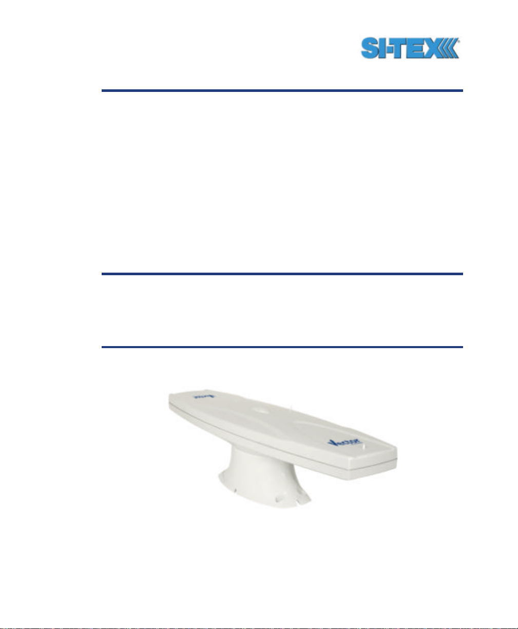
Figure 1-1 shows the V ector PRO mounted on the fixed base.
Figure 0-1 Vector PRO
Vector PRO Reference Manual 23
Page 24

The Vector PRO is composed of three main pieces; the Vector PRO,
the mounts, and the power / data cable. The remaining parts are the
manual, screws, and screwdriver bits.
If you are new to GPS and SBAS, we recommend that you consult
Appendix B for further information on these services and technology
before proceeding.
1.1 Receiving Your Shipment
If you find that any of these items are damaged due to shipment, please
contact the freight carrier immediately for assistance.
1.2 Unpacking Your Vector PRO System
When you unpack your Vector PRO system, please ensure that it is
complete by comparing the parts received against the packing slip.
Unless your system has intentionally been equipped differently than a
standard Vector PRO, you should find the following parts in your
system.
• One Vector PRO receiver (P/N 804-0020-01A or greater) or
• One Vector Lite (P/N 804-0021-03A or greater)
• One pole mount (P/N 603-1002-000)
• One fixed mount (P/N603-1001-000)
• One power / data cable - 15 m (P/N 051-0063-003)
• One Vector PRO Manual (P/N 875-0076-000)
• One set of base mounting screws (8 pieces) (P/N 675-1078-000)
• Two T-20 Torx screwdriver bit for base mount ing (P/N 675-0037-000)
• One 1-14-UNS stainless steel jam nut (P/N 676-1003-000)
• One stainless steel washer (P/N 678-1039-000)
Vector PRO Reference Manual 24
Page 25
Note - If, for some reason, you find a discrepancy between your
packing slip and the contents of your shipment, please contact
the sales person with which you placed your order.
1.3 Vector PRO Interface
The Vector PRO features a single power / data connection located on
the bottom of the enclosure. This connector, when mated with the
cable-mounted connector is weatherproof. Additionally, when the
mounting base is fitted, this will provide addition protection from the
elements. The following figure shows the Vector PRO’s power / data
connection.
Figure 0-2 Cable Interface
1.4 Understanding the Vector PRO
The purpose of the Vector PRO system is to provide accurate, reliable
heading and position information at high update rates. To accomplish
this task, the Vector PRO uses two internal high performance GPS
engines and two multipath-resistant antennas for GPS signal
processing. One pair of receiver and antenna is designated the primary
GPS and the second pair is designated as the secondary GPS.
Vector PRO Reference Manual 25
Page 26

Positions computed by the Vector PRO are referenced to the phase
center of the primary GPS antenna. Heading data references the vector
formed from the primary GPS antenna phase center to the secondary
GPS antenna phase center.
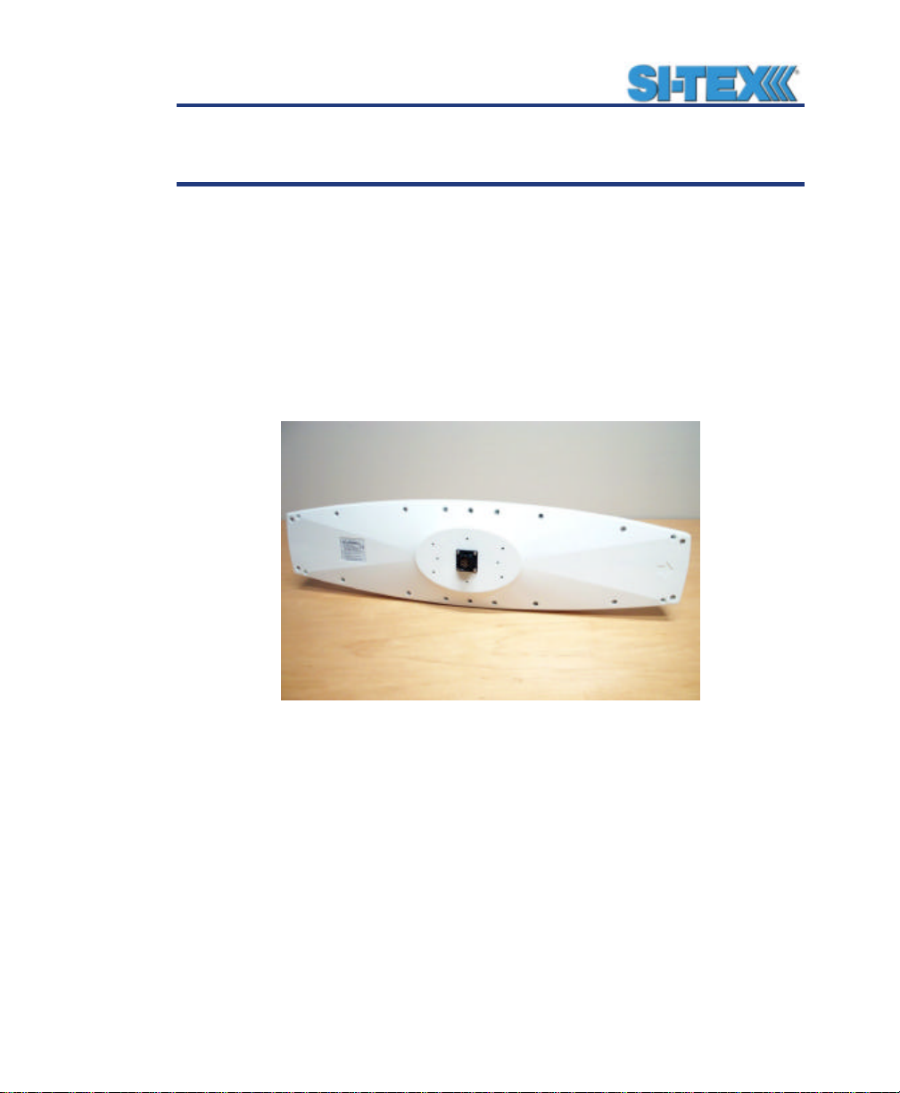
The following figure shows the location of a heading arrow on the
bottom of the Vector PRO enclosure, which defines system orientation.
The arrow points in the direction that the heading measurement is
computed (when the antenna is installed parallel to the fore-aft line of
the vessel). The antenna inside the enclosure directly above the arrow
is the secondary antenna.
1.4.1 Moving Base Station RTK
The Vector PRO’s internal GPS engines use both the L1 GPS C/A code
and carrier phase data to compute the location of the secondary GPS
antenna in relation to the primary GPS antenna with a very high subcentimeter level of precision. The technique of computing the location
of the secondary GPS antenna with respect to the primary antenna,
when the primary antenna is moving, is often referred to as moving
base station Real-Time Kinematic (or moving base station RTK).
RTK technology generally is very sophisticated and requires a
significant number of possible solutions to be analyzed where various
combinations of integer numbers of L1 wavelengths to each satellite
intersect within a certain search volume. The integer number of
wavelengths is often referred to as the Ambiguity as they are initially
ambiguous at the start of the RTK solution.
The Vector PRO places a constraint on the RTK solution with the prior
knowledge of the fact that the secondary GPS antenna has a fixed
separation of 0.50 m from the primary GPS antenna on the bracket of
the Antenna Array. This reduces the search volume considerably (and
hence startup times) since the location of the secondary antenna can
theoretically fall only on the surface of a sphere with radius 0.50 m
centered on the location of the primary antenna (versus a normal
search volume that’s greater than a cubic meter).
Vector PRO Reference Manual 26
Page 27

1.4.2 Supplemental Sensors - Reduced Search Time
In addition to incorporating two internal GPS engines, integrated inside
the Vector PRO are a gyro, magnetometer, and a tilt sensor. When
used, the combination of the tilt sensor and the magnetometer aid the
rate at which a heading solution is computed on startup and also during
reacquisition if the GPS heading is lost due to obstructions. Each
supplemental sensor may be turned on or off individually, however, the
full functionality of the Vector PRO system is realized only when all are
used. Each supplemental sensor is inside the Vector PRO enclosure,
mounted on the internal printed circuit board.
The tilt sensor reduces the search volume further beyond the volume
associated with just a fixed antenna separation, since the Vector PRO
knows the approximate inclination of the secondary antenna with
respect to the primary. The magnetic sensor is able to provide a
general indication of the true heading, reducing the search volume
further. The gyro has a similar benefit as the magnetic sensor, however
only on reacquisition since it initially requires a GPS heading to selfcalibrate. The gyro is more accurate for the short term than the
magnetic heading sensor and it further reduces the search volume.
Reducing the RTK search volume also has the benefit of improving the
reliability and accuracy of selecting the correct heading solution by
eliminating other possible, erroneous solutions.
Note - By default, the tilt aiding is turned on, however, the gyro
and the magnetic sensors are turned off for shipping. The gyro
sensor may be turned on at any time by sending a configuration
command to the Vector PRO. The magnetic sensor should be
turned on when Vector is mounted in its final location.
1.4.3 Supplemental Sensors - Heading System
Backup
The magnetic sensor and the gyro are able to operate as secondary
sources of heading during periods of GPS outage due to obstruction.
We require that you turn on the magnetic aiding once the installation is
complete. You may configure the Vector PRO to use the gyro aiding if
Vector PRO Reference Manual 27
Page 28

you choose. Since the gyro is more accurate than the magnetic sensor
for short periods of outage, if both sensors are used, the Vector PRO
will use the gyro for heading initially during an outage. If the outage lasts
longer than 60 seconds, the gyro will be deemed to have drifted too far
and the Vector PRO will begin outputting a heading based upon the
magnetic sensor. There is no user control over the time -out period of
the gyro.
If the gyro is turned off and the magnetic sensor is the only secondary
heading source, it will provide a heading indefinitely until a GPS heading
has been reacquired.
1.5 Installation Overview
The following list summarizes the primary installation steps and points
for consideration to successfully install and configure the Vector PRO
system.
• Choose a mounting location with no structures above its horizon - failure to
do so can reduce heading accuracy, startup times, signal reacquisition times,
positioning accuracy, and availability of satellite signals from both GPS and
SBAS. Make sure the Antenna Array is mounted away from other electronics
and antennas (especially active TV antennas) by at least a few feet, preferably
more. Keep in mind that the position computed by the Vector PRO is
referenced to the phase center of the primary GPS antenna, which is
approximately 5.7 cm (2.25”) from the aft-end of the Vector PRO enclosure,
residing on its centerline.
• You may want to install the Vector PRO on the vessel’s axis so the resulting
position from the primary GPS receiver agrees with the centerline of the vessel.
The Vector PRO does not support a command to translate its position to the
vessel centerline if the enclosure is mounted offset from the centerline.
• The location that you choose to mount the Vector PRO should be a quiet
location from a radio frequency perspective. This should location should have an
omni directional view of the horizon and be mounted reasonably high (keeping in
mind serviceability). This will ensure that you minimize outside interference with
beacon reception.
• Determine how you wish to install the Antenna Array (either along the boat’s
fore-aft line or athwartship (perpendicular to it) - this depends on whether or not
Vector PRO Reference Manual 28
Page 29

you would like to use the second dimension of attitude that the Vector PRO
provides - either pitch or roll)
• Choose either the fixed or pole mount for the installation, based on what will
most easily meet your needs. If you choose to use the pole mount, ensure that
once the Vector PRO is mounted, its orientation will not change over time as
this will affect the heading result.
• Connect the power / dat a cable to the Vector PRO before you fasten on the
fixed mount or pole mount.
• Power the Vector PRO only with an input voltage between 8 and 40 VDC.
• Install the Vector PRO so that it is horizontal (as best as can be accomplished
- this will provide a foundation for performance success when the internal tilt
sensor is used to supplement Vector PRO operation).
• Compensate for any heading offset of the Vector PRO, its configuration (the
default is no compensation)
• Configure the NMEA data message output from the Vector (by default, Port A
and B output GGA, VTG, GSV, ZDA, HDT, and ROT at 1 Hz)
• Configure the baud rates if necessary (default is 19,200 for Port A and B)
• Configure the supplementary sensors if necessary (the tilt sensor operates by
default and the magnetic sensor and gyro are disabled, but, the magnetic sensor
is required to be on after installation is complete)
• Configure for your desired mode of differential operation (either SBAS, beacon,
or external corrections – SBAS corrections are default)
• If you are using the second dimension of attitude provided by the Vector PRO
(either roll or pitch, depending on the Antenna Array orientation), configure the
Vector PRO appropriately (the default is pitch)
• Compensate for pitch / roll error due to installation, within the Vector PRO
configuration (the default is no compensation)
• If your application does not involve pitching or rolling of more than 10? from
horizontal, configuring the Vector PRO for level operation will reduce startup and
reacquisition times significantly
1.6 Mounting Configurations and Offset
Settings
There are two primary mounting orientations possible with the Vector
PRO system. The first and most common method is to mount the
Vector PRO enclosure pointing in a direction parallel to the axis of the
boat, facing the bow. This mounting configuration will provide the ability
Vector PRO Reference Manual 29
Page 30

for the Vector PRO system to output both heading and the pitch of the
vessel.
If a gyrocompass is present onboard, this could be used as truth to
calibrate the physical heading of the Vector PRO and its corresponding
heading measurements to true heading of the boat by entering a
heading bias into the Vector PRO configuration. For example, if a
gyrocompass heading provides 183.2? while the Vector PRO provides a
heading reading of 184.0?, a bias of -0.8? (the bias is added) should be
programmed into the Vector PRO to calibrate its heading. Obviously,
the Vector PRO could be adjusted physically to correct for this
deviation.
The second method of mounting the Vector PRO system to mount the
Vector PRO perpendicular to the boat’s symmetrical axis. This
orientation will provide the heading and roll of the vessel. The Vector
PRO is then configured with a heading bias of +90? or -90? (depending
if the Vector PRO points to port or starboard) to correct the heading.
A feature is present in the Vector PRO to change the sign of the roll /
pitch measurement to be positive or negative, depending on the
required convention for positive / negative roll, if needed. Co nsult
Chapter 6 for further information.
1.7 Gyro Initialization Process
When the gyro is first initializing itself, it is important that the dynamics
that the gyro experiences during this warm-up period are similar to the
regular operating dynamics. For examp le, if you will be using the Vector
on a high speed, maneuverable craft, it is essential that when gyro
aiding in the Vector is first turned on that it be used for the first 5 to 10
minutes in an environment that has high dynamics as well, instead of
just sitting stationary.
Vector PRO Reference Manual 30
Page 31

1.8 NMEA 0183 Message Interface
The Vector PRO uses the common NMEA 0183 interface, which allows
you to easily make configuration changes by sending text-type
commands to the receiver.
Each of the following sections provide the appropriate commands for
making the configuration change discussed. The NMEA interface of the
Vector PRO is described in more detail in Chapter 6.
1.8.1 Tilt Aiding
The Vector PRO’s internal tilt sensor (accelerometer) is enabled by
default, is factory calibrated, and constrains the RTK heading solution to
reduce startup and reacquisition times.
To turn the tilt-aiding feature off, use the following command.
$JATT,TILTAID,NO<CR><LF>
You may turn this feature back on with the following command.
$JATT,TILTAID,YES,<CR><LF>
To query the Vector PRO for the current status of this feature, issue the
following command.
$JATT,TILTAID<CR><LF>
1.8.2 Tilt Sensor Calibration
The tilt sensor within the Vector PRO is pre-calibrated during the
manufacturing process so it’s not necessary that it be recalibrated in
the field. If, for some reason, recalibration is necessary, Chapter 6
describes the command and methodology required to recalibrate this
sensor.
Vector PRO Reference Manual 31
Page 32

1.8.3 Magnetic Aiding
For shipping purposes, magnetic aiding is disabled, but, it is required to
be turned on and calibrated when the final installation is complete. The
Vector’s internal magnetometer reduces the time required to compute a
heading solution on startup and during GPS reacquisition by
constraining the moving base station RTK solution. Further, it reduces
the likelihood of computing the wrong GPS solution. With an
approximate heading from the magnetometer, the search volume for the
RTK solution is reduced, since the Vector has a general indication of
the direction of the secondary GPS antenna.
The magnetic sensor also can provide a secondary source of heading
output in the event that a GPS outage occurs due to signal obstruction.
Use of the magnetic aiding feature is now required, but, for shipping
purposes, this feature is disabled. In addition to reducing the time
required to compute a heading solution, it can also provide a secondary
source of heading when a GPS heading is not available. When you are
ready to turn the magnetic aiding feature on, there are two different
ways of calibrating. The magnetic sensor must be calibrated after the
completion of the installation process.
To turn the magnetic-aiding feature on, use the following command.
$JATT,MAGAID,YES<CR><LF>
You may turn this feature back off with the following command.
$JATT,MAGAID,NO<CR><LF>
To query the Vector for the current status of this feature, issue the
following command.
$JATT,MAGAID<CR><LF>
Vector PRO Reference Manual 32
Page 33

1.8.4 Magnetometer Calibration
Metallic structures on the vessel affect a compass’ reading, so this
effect must be ‘removed’ through the calibration process. Once the
Vector is installed in its final location, to use this feature, magnetic
aiding must first be turned on, followed by its calibration. A valid GPS
heading is mandatory for the calibration process. There are two
different ways to calibrate the magnetometer.
The first way is to send a command to clear the current magnetic
information to begin the initialization process.
$JATT,MAGCLR<CR><LF>
Then, if you leave the unit powered continuously, it will automatically
save the magnetic calibration tables when the system has sufficiently
sampled the magnetic field with numerous rotations. Depending on this
dynamics of your vessel, this may several days. For instance, if this
system is being used on a large cargo vessel that may only see
significant rotation during harbor approaches or maneuvers within a port
or channel, this process may take many days. Thereafter, there is no
further calibration required. If you wish to check if the magnetic
information has been saved, you can issue the following command.
$JATT,MAGCAL<CR><LF>
The second method requires more work up front, but ensures your
magnetic calibration information is up to date and complete within a
short period of time. A command to clear the current magnetic
information mu st first be sent to begin the initialization process, followed
by slowly rotating the vessel a full 360? approximately 3 to 10 times.
Calibration should be performed in a clear environment without any
potential satellite blockages to minimize any possible errors during the
process. The command to initialize the magnetic calibration process
follows.
$JATT,MAGCLR<CR><LF>
Vector PRO Reference Manual 33
Page 34

Once the command has been issued, the vessel needs to rotate 360?
three to four times. The following command can be sent during the
calibration procedure to ‘ask’ the Vector if the calibration is complete
and if so, to automatically save it to memory for subsequent power
cycles.
$JATT,MAGCAL<CR><LF>
If the Vector enclosure is reinstalled in a different location, even on the
same vessel, you will need to clear the calibration table with the
$JATT,MAGCLR command and complete the new calibration. Similarly,
if any objects containing metal are moved near or away from the
sensor, this command will need to be sent to the receiver and a new
calibration performed.
Note - It is very important to perform the calibration only after the
installation of the Vector has been confirmed to be complete. If
the Vector’s location is changed, you will need to clear the
calibration and recalibrate. A valid GPS heading is required
during the calibration process.
1.8.5 Gyro Aiding
The Vector PRO’s internal gyro is not used by default, however it can
offer two benefits. It will shorten reacquisition times when a GPS
heading is lost, due to obstruction of satellite signals, by reducing the
search volume required for solution of the RTK. It will also provide an
accurate substitute heading for a short period (depending on the roll and
pitch of the vessel) ideally seeing the system through to reacquisition.
Should you wish to use gyro-aiding, you will need to turn it on using the
following command.
$JATT,GYROAID,YES<CR><LF>
If you wish to turn this feature off, the use the following command.
$JATT,GYROAID,NO<CR><LF>
Vector PRO Reference Manual 34
Page 35

If you wish to request the status of this message, send the following
command.
$JATT,GYROAID<CR><LF>
1.8.6 Time Constants
The Vector PRO incorporates user-configurable time constants that
can provide a degree of smoothing to the heading, course over ground,
and speed measurements. The following sections describe how to
configure their values.
1.8.6.1 Heading Time Constant
The heading time constant allows you to adjust the level of
responsiveness of the true heading measurement provided in the
$HEHDT message. The default value of this constant is 2.0 seconds of
smoothing when the gyro is enabled. The gyro by default is enabled, but
can be turned off. By turning the gyro off, the equivalent default value of
the heading time constant would be 0.5 seconds of smoothing. This is
not done automatically, and therefore must be entered manually by the
user. Increasing the time constant will increase the level of heading
smoothing.
The following command is used to adjust the heading time constant.
$JATT,HTAU,htau<CR><LF>
Where ‘htau’ is the new time constant that falls within the range of 0.0 to
3600.0 seconds.
Depending on the expected dynamics of the vessel, you may wish to
adjust this parameter. For instance, if the vessel is very large and is not
able to turn quickly, increasing this time is reasonable. The resulting
heading would have reduced ‘noise’, resulting in consistent values with
time. However, artificially increasing this value such that it does not
agree with a more dynamic vessel could create a lag in the heading
measurement with higher rates of turn. A convenient formula for
determining what the level of smoothing follows for when the gyro is in
Vector PRO Reference Manual 35
Page 36

use. If you are unsure on how to set this value, it’s best to be
conservative and leave it at the default setting.
htau (in seconds) = 40 / maximum rate of turn (in ?/s) – gyro ON
htau (in seconds) = 10 / maximum rate of turn (in ?/s) – gyro OFF
You may query the Vector for the current heading time constant by
issuing the same command without an argument.
$JATT,HTAU<CR><LF>
Note - If you are unsure of the best value for this setting, it’s best
to be conservative and leave it at the default setting of 2.0
seconds when the gyro is on and at 0.5 seconds when the gyro is
off.
1.8.6.2 Pitch Time Constant
The pitch time constant allows you to adjust the level of responsiveness
of the pitch measurement provided in the $PSAT,HPR message. The
default value of this constant is 0.5 seconds of smoothing. Increasing
the time constant will increase the level of pitch smoothing.
The following command is used to adjust the pitch time constant.
$JATT,PTAU,ptau<CR><LF>
Where ‘ptau’ is the new time constant that falls within the range of 0.0 to
3600.0 seconds.
Depending on the expected dynamics of the vessel, you may wish to
adjust this parameter. For instance, if the vessel is very large and is not
able to pitch quickly, increasing this time is reasonable. The resulting
pitch would have reduced ‘noise’, resulting in consistent values with
time. However, artificially increasing this value such that it does not
agree with a more dynamic vessel could create a lag in the pitch
measurement. A convenient formula for determining what the level of
Vector PRO Reference Manual 36
Page 37

smoothing follows. If you are unsure on how to set this value, it’s best
to be conservative and leave it at the default setting.
ptau (in seconds) = 10 / maximum rate of pitch (in ?/s)
You may query the Vector PRO for the current pitch time constant by
issuing the same command without an argument.
$JATT,PTAU<CR><LF>
Note - If you are unsure of the best value for this setting, it’s best
to be conservative and leave it at the default setting of 0.5
seconds.
1.8.6.3 Heading Rate Time Constant
The heading rate time constant allows you to adjust the level of
responsiveness of the rate of heading change measurement provided in
the $HEROT message. The default value of this constant is 2.0
seconds of smoothing. Increasing the time constant will increase the
level of heading smoothing.
The following command is used to adjust the heading time constant.
$JATT,HRTAU,hrtau<CR><LF>
Where ‘hrtau’ is the new time constant that falls within the range of 0.0
to 3600.0 seconds.
Depending on the expected dynamics of the vessel, you may wish to
adjust this parameter. For instance, if the vessel is very large and is not
able to turn quickly, increasing this time is reasonable. The resulting
heading would have reduced ‘noise’, resulting in consistent values with
time. However, artificially increasing this value such that it does not
agree with a more dynamic vessel could create a lag in the rate of
heading change measurement with higher rates of turn. A convenient
formula for determining what the level of smoothing follows. If you are
Vector PRO Reference Manual 37
Page 38

unsure on how to set this value, it’s best to be conservative and leave it
at the default setting.
hrtau (in seconds) = 10 / maximum rate of the rate of turn (in ?/s2)
You may query the Vector PRO for the current heading rate time
constant by issuing the same command without an argument.
$JATT,HRTAU<CR><LF>
Note - If you are unsure of the best value for this setting, it’s best
to be conservative and leave it at the default setting of 2.0
seconds.
1.8.6.4 Course over Ground Time Constant
The course over ground (COG) time constant allows you to adjust the
level of responsiveness of the COG measurement provided in the
$GPVTG message. The default value of this constant is 0.0 seconds of
smoothing. Increasing the time constant will increase the level of COG
smoothing.
The following command is used to adjust the COG time constant.
$JATT,COGTAU,cogtau<CR><LF>
Where ‘cogtau’ is the new time constant that falls within the range of 0.0
to 3600.0 seconds.
COG is computed using the primary GPS engine only, and its accuracy
is dependant upon the speed of the vessel (noise is proportional to
1/speed) and when stationary, this value is invalid.
As with the heading time constant, the setting of this value depends
upon the expected dynamics of the vessel. If a boat is highly dynamic,
this value should be set to a lower value since the filtering window
needs be shorter in time, resulting in a more responsive measurement.
However, if a vessel is very large and has much more resistance to
change in its motion, this value can be increased to reduce
Vector PRO Reference Manual 38
Page 39

measurement noise. The following formula provides some guidance on
how to set this value. If you are unsure what is the best value for this
setting, it’s best to be conservative and leave it at the default setting.
cogtau (in seconds) = 10 / maximum rate of change of course (in ?/s)
You may query the Vector PRO for the current heading time constant by
issuing the same command without an argument.
$JATT,COGTAU<CR><LF>
Note - If you are unsure of the best value for this setting, it’s best
to be conservative and leave it at the default setting of 0.0
seconds.
1.8.6.5 Speed Time Constant
The speed time constant allows you to adjust the level of
responsiveness of the speed measurement provided in the $GPVTG
message. The default value of this parameter is 0.0 seconds of
smoothing. Increasing the time constant will increase the level of speed
measurement smoothing.
The following command is used to adjust the speed time constant.
$JATT,SPDTAU,spdtau<CR><LF>
Where ‘spdtau’ is the new time constant that falls within the range of 0.0
to 3600.0 seconds.
Speed is computed using the primary GPS engine only. As with the
heading time constant, the setting of this value depends upon the
expected dynamics of the vessel. If a boat is highly dynamic, this value
should be set to a lower value since the filtering window would be
shorter, resulting in a more responsive measurement. However, if a
vessel is very large and has much more resistance to change in its
motion, this value can be increased to reduce measurement noise. The
following formula provides some guidance on how to set this value
initially, however, we recommend that you test how the revised value
Vector PRO Reference Manual 39
Page 40

works in practice. If you are unsure what is the best value for this
setting, it’s best to be conservative and leave it at the default setting.
spdtau (in seconds) = 10 / maximum acceleration (in m/s2)
You may query the Vector PRO for the current heading time constant by
issuing the same command without an argument.
$JATT,SPDTAU<CR><LF>
Note - If you are unsure of the best value for this setting, it’s best
to be conservative and leave it at the default setting of 0.0
seconds.
1.8.7 Level Operation
If the Vector PRO system will operate in a level plane (within ? 10? from
horizontal), an additional constraint can be placed upon the RTK
heading solution in order to reduce the RTK search time and increase
solution robustness. This feature, referred to as ‘level operation’ is
disabled by default but can be invoked using the following command.
$JATT,LEVEL,YES<CR><LF>
To turn this feature off, issue the following command.
$JATT,LEVEL,NO<CR><LF>
To determine the current status of this message, issue the following
command.
$JA TT,LEVEL<CR><LF>
1.8.8 Heading Compensation
You may adjust the heading output from the Vector PRO in order to
correct for any physical offset of the enclosure from the true heading of
the vessel.
Vector PRO Reference Manual 40
Page 41

$JATT,HBIAS,x<CR><LF>
Where x is a bias that will be added to the Vector PRO’s heading, in
degrees. The acceptable range for the heading bias is -180.0? to
180.0?. The default value of this feature is 0.0?.
To determine what the current heading compensation angle is, send the
following message to the Vector PRO.
$JATT,HBIAS<CR><LF>
1.8.9 Configuring for Pitch or Roll
The mounting orientation of the Vector PRO determines if the second
dimension of vessel orientation will be roll or pitch. As mentioned, if you
install the Vector PRO parallel to the axis of the boat, it will provide pitch
in addition to heading. If the Array were mounted athwartship
(perpendicular to the vessel axis), the second dimension of orientation
would be roll.
If you install the Vector PRO in a parallel direction as the boat’s axis,
you do not need to make any configuration changes to receive the pitch
measurement - you need to only turn the appropriate message on (the
$PSAT,HPR message).
If you wish to get the roll measurement, you will need to install the
Vector PRO perpendicular to the vessel’s axis, and send the following
command to the unit.
$JATT,ROLL,YES<CR><LF>
If you wish to return the Vector PRO to its default mode of outputting the
pitch measurement, issue the following command.
$JATT,ROLL,NO<CR><LF>
You may query the Vector PRO for the cu rrent roll / pitch status with the
following command.
Vector PRO Reference Manual 41
Page 42

$JATT,ROLL<CR><LF>
1.8.10 Configuring Negative Pitch or Roll
When the secondary GPS antenna is below the primary GPS antenna,
the angle from the horizon at the primary GPS antenna to the secondary
GPS antenna is considered negative by default.
Depending on your convention for positive and negative pitch / roll, you
may wish to change the sign (either positive or negative) of the pitch /
roll. To do this, issue the following command.
$JATT,NEGTILT,YES<CR><LF>
This will cause the pitch measure to be positive when the secondary
GPS antenna is below the primary GPS antenna.
To return the sign of the pitch / roll measurement to its original value,
issue the following command.
$JATT,NEGTILT,NO<CR><LF>
To query the Vector PRO for the current state of this feature, issue the
following command.
$JATT,NEGTILT<CR><LF>
1.8.11 Pitch / Roll Compensation
If you have installed the Vector PRO and you have it correctly aligned,
but there is a bias in the amount of tilt that it has, or it’s not fully
horizontal, you may adjust the pitch / roll output from the Vector PRO in
order to calibrate the measurement. The following NMEA message
allows to you to calibrate the pitch / roll reading from the Vector PRO.
$JATT,PBIAS,x<CR><LF>
Vector PRO Reference Manual 42
Page 43

Where x is a bias that will be added to the Vector PRO’s pitch / roll
measure, in degrees. The acceptable range for the heading bias is -
15.0? to 15.0?. The default value of this feature is 0.0?.
To determine what the current pitch compensation angle is, send the
following message to the Vector PRO.
$JATT,PBIAS<CR><LF>
Note - The pitch / roll bias is added after the negation of the pitch
/ roll measurement (if so invoked with the $JATT,NEGTILT
command).
1.8.12 Forcing a New RTK Search
You may force the Vector PRO to reject the current RTK heading
solution, and have it begin a new search with the following command.
$JATT,SEARCH<CR><LF>
1.8.13 Summary Command
This command is used to receive a summary of the current Vector
PRO settings. This command has the following format.
$JATT,SUMMARY<CR><LF>
The Vector PRO will reply with the following output.
$>JATT,SUMMARY,TAU:H=0.50,HR=2.00,COG=0.00,SPD=0.00,BIAS:
H=0.00,P=0.00,FLAG_HEX:GN-RMTL=01
Chapter 6 summarizes this output in detail.
1.8.14 HELP command
The Vector PRO supports a command that you can use to get a short
list of the supported commands if you find yourself in the field without
documentation.
Vector PRO Reference Manual 43
Page 44

This commands has the following format.
$JATT,HELP<CR><LF>
The response to this command will be the following.
$>JATT,HELP,CSEP,MSEP,EXACT,LEVEL,HTAU,HRTAU,HBIASPBIA
S,NEGTILT,ROLL,TILTAID,TILTCAL,MAGAID,MAGCAL,MAGCLR,
GYROAID,COGTAU,SPDTAU,SEARCH,SUMMARY
1.8.15 $HEHDT Message
This message provides true heading of the vessel. This is the direction
that the vessel (Vector PRO) is pointing and is not necessarily the
direction of vessel motion (the course over ground), although they may
be the same.
The COG measurement in the $GPVTG message describes the true
direction of travel of the boat as a result of the vessel trust, currents,
wind, etc. Please note that the COG measure is derived from the
primary GPS receiver only and is less accurate than the true heading
derived using the RTK solution that uses both GPS receivers.
The $HEHDT message output rate may be configured with the following
command.
$JASC,HEHDT,rate<CR><LF>
Where ‘rate’ may be any of the following values expressed in Hz: 0, 1, 5,
10, or 0.2.
The output from the $JSHOW<CR><LF> command provides the
current output rate setting for this message.
The details of this command and the $HEHDT are described in Chapter
6.
Vector PRO Reference Manual 44
Page 45

1.8.16 $HEROT Message
This message provides rate of turn of the vessel and has units of
degrees per second.
The $HEHDT message output rate may be configured with the following
command.
$JASC,HEROT,rate<CR><LF>
Where ‘rate’ may be any of the following values expressed in Hz: 0, 1, 5,
10, or 0.2.
The output from the $JSHOW<CR><LF> command provides the
current output rate setting for this message.
The details of this command and the $HEROT message are described
in Chapter 6.
1.8.17 Proprietary $PSA T,INTLT Message
The $PSAT,INTLT data message is a proprietary NMEA sentence that
provides the tilt measurement from the internal inclinometer, in degrees.
This message can be output only at 1 Hz and is turned on using the
following command.
$JASC,INTLT,1<CR><LF>
To turn this message off, use the following command.
$JASC,INTLT,0<CR><LF>
The details of this command and the $PSAT,INTLT message are
described in Chapter 6.
1.8.18 Proprietary $PSAT,HPR Message
The $PSAT,HPR message is a proprietary NMEA sentence that
provides the heading, pitch / roll information, and time in a single data
Vector PRO Reference Manual 45
Page 46

message. The output of this data message is controlled using the
following message.
$JASC,HPR,rate<CR><LF>
Where ‘rate’ may be any of the following values expressed in Hz: 0, 1, 5,
10, or 0.2.
The details of this command and the $PSAT,HPR data message are
described in Chapter 6.
Vector PRO Reference Manual 46
Page 47

2. Installation
This chapter contains instructions and recommendations for the
installation of the Vector PRO GPS heading system.
2.1 System Parts List
The followi ng list of standard equipment is included with the Vector
PRO.
• One Vector PRO receiver (P/N 804-0020-01A or greater) or
One Vector Lite (P/N 804-0021-03A or greater)
• One pole mount (P/N 603-1002-000)
• One fixed mount (P/N603-1001-000)
• One power / data cable - 15 m (P/N 051-0063-003)
• One Vector PRO Manual (P/N 875-0076-000)
• One set of base mounting screws (8 pieces) (P/N 675-1078-000)
• Two T-20 Torx screwdriver bit for base mounting (P/N 675-0037-000)
• One 1-14-UNS stainless steel jam nut (P/N 676-1003-000)
• One stainless steel washer (P/N 678-1039-000)
2.2 Installation Overview
The following sub-sections summarize the installation steps for the
Vector PRO, which differs depending on which mount that you choose.
2.2.1 Fixed Base Installation
When using the fixed base mount, the following list provides an
overview of the installation process.
• Choose a mounting location for the Vector PRO
• Determine if you wish to use the second dimension of attitude being either the
roll or the pitch. If you wish to use the roll measure, you must install the Vector
PRO perpendicular to the direction of travel and then accommodate for this
orientation in the receiver software configuration)
Vector PRO Reference Manual 47
Page 48

• Connect the power / data cable connector to the Vector PRO connector,
ensuring the locking ring has positively locked
• Fasten the Vector PRO enclosure to the fixed base mount
• Route the cable from this location through fixed base mount, through the
mounting surface, and any bulkheads as necessary (leave enough slack to
remove the Vector PRO from the fixed base as necessary)
• Install the fixed base mount without tightening down the screws fully, to allow
for adjustment at a later step
• Adjust the orientation of the Vector PRO as necessary and secure it when
complete (you may wish to use the ‘alignment sights’ on the top of the
enclosure for this purpose)
• Interface the Vector PRO to a PC computer for configuration of the
communication settings, data message output, and any offset that’s necessary.
2.2.2 Pole-mounting Base Installation
The following list details the installation process when using the pole
mount.
• Choose a mounting location for the Vector PRO
• Determine if you wish to use the second dimension of attitude being either the
roll or the pitch. If you wish to use the roll measure, you must install the Vector
PRO perpendicular to the direction of travel and then accommodate for this
orientation in the receiver software configuration)
• Install the mounting pole as necessary
• Thread the hex nut and then the washer onto the threaded pole
• Thread the Vector PRO’s pole-mounting base onto the threaded pole (do not
tighten down at this point to allow for adjustment of orientation at a later time)
• Route the cable through the pole mount, pole, and any bulkheads as
necessary (leave enough slack to remove the Vector PRO from the polemounting base as necessary)
• Connect the cable-mounted connector to the Vector PRO bulkhead connector,
ensuring the locking ring has positively locked
• With the Vector PRO approximately facing the final direction, align the polemounting base and nut / washer combination to the GPS compass. Fasten the
Vector PRO enclosure to the pole-mounting base
• Adjust the orientation of the Vector PRO as necessary and secure it when
complete (you may wish to us e the ‘alignment sights’ on the top of the
enclosure for this purpose)
• Interface the Vector PRO to a PC computer for configuration of the
communication settings, data message output, and any offset that’s necessary.
Vector PRO Reference Manual 48
Page 49

2.3 Vector PRO Interface
The following figure shows the location of the connector located on the
bottom of the Vector PRO enclosure. This connector is the only
interface to the product and includes the power input and the serial
communication input / output.
Figure 2-1 Vector PRO Interface
2.4 Choosing a Mounting Location
When considering the various mounting locations present, you will need
to give regard for both GPS (and hence SBAS) and beacon reception.
The following two sections provide information that will help you
determine the best location for the Vector PRO.
2.4.1 GPS Reception
When considering various locations to mount the Vector PRO, consider
the following recommendations cl osely.
• The primary GPS engine inside the Vector PRO computes a position based
upon measurements from each satellite to the internal primary GPS antenna
Vector PRO Reference Manual 49
Page 50

element. Mount the Vector PRO in the location for which you desire a position
with respect to the primary GPS antenna.
• When choosing a location to mount the antenna, please ensure that there is an
unobstructed hemisphere of sky available to the Vector PRO. This will ensure
that GPS and SBAS satellites are not masked by obstructions, potentially
reducing system performance.
• It’s important to locate any transmitting antennas away from the Vector PRO
by at least a few feet. This will ensure that tracking performance is not
compromised, giving you the best performance possible.
• Make sure that you have enough cable length to route into the vessel, in order
to reach a breakout box or terminal strip.
• Do not locate the antenna where environmental conditions exceed those
specified in Section 2.4.
2.4.2 Beacon Reception
When using the Vector PRO’s internal beacon receiver as the
correction source, you will need to consider the possible mounting
locations from a perspective of ambient noise within the beacon band.
The following list provides some general guidelines for deciding upon a
location with respect to maximizing beacon performance.
• Ensure that the antenna is as far as possible from all other equipment that
emits Electromagnetic Interference (EMI), including DC motors, alternators,
solenoids, radios, power cables, display units, and other electronic devices
• If you are installing the antenna on a vessel (using DGPS beacon corrections),
mount the Vector PRO antenna as high as possible, considering maintenance
and accessibility. In addition, ensure that the antenna is lower than the highest
metal object on the vessel.
• If a radar system is present, mount the antenna outside the path of the radar
beam
The Vector PRO’s internal beacon receiver calculates a Signal to Noise
Ratio (SNR), measured in dB (Decibels) that indica tes the receiver’s
performance. The SNR is height of the signal above the noise floor.
The higher the SNR, the better your beacon receiver is demodulating
the signal. The optimum antenna location will be a position where your
average SNR is highest. You should turn on all accessories that you
intend to use during normal operation when locating the best position for
the antenna. By monitoring the SNR, you can determine the optimum
Vector PRO Reference Manual 50
Page 51

location with respect to beacon reception. The SNR is available in the
$CRMSS NMEA message described in Chapter 6.
Note – Beacon data is only accessible via primary GPS Port A and
B. The secondary GPS Port A does not provide access to the
beacon receiver.
2.5 Environmental Considerations
The Vector PRO is designed to withstand the harsh outdoor
environment, however, there are specific environmental limits that you
should ensure are met when storing and using this system.
The Vector PRO is designed to be stored between -40?C and +85?C.
The operating temperature range is -30?C and +70?C. It is designed for
harsh marine use and will operate in an environment with 100% relative
humidity.
2.6 Power Considerations
The Vector PRO is powered with an input voltage of between 8 and 40
VDC. For best performance, the supplied power should be continuous
and clean. Table 2-1 details the power specifications of the Vector
PRO.
Table 2-1 Power Requirements
Input Voltage Input Current Input Power
8 to 40VDC <360 mA @ 12 VDC <4.5 W maximum
The Vector PRO power supply features reverse polarity protection but
will not operate with reverse polarity power.
2.7 Electrical Isolation
Vector PRO Reference Manual 51
Page 52

The Vector PRO features a power supply that is isolated from the
communication lines. Further, the PC-ABS plastic enclosure isolates
the electronics mechanically from the vessel. This addresses the issue
of vessel hull electrolysis.
2.8 Vector PRO Mounting
The Vector PRO may be mounted with either the fixed base or polemounting base, both supplied with the system.
The fixed base allows you to mount the Vector PRO on a wide array of
flat surfaces, such as radar platforms. The pole mount is designed for
use with 1-14-UNS-2B threaded mounts, such as pole and rail mounts.
Note - Installations that use the pole mount require the use of the
supplied hexagonal jam nut and flat washer in order to
mechanically couple the Vector PRO system to the pole mount
with less stress on the threads. If the nut / washer combination is
not used, failure of the pole mounting base could occur, which
may damage the Vector PRO. Any such damage to the Vector
PRO system resulting from not using the nut / washer
combination is not covered under warranty.
Vector PRO Reference Manual 52
Page 53

The following figure shows the Vector PRO mounted with the fixed
base.
Figure 2-2 Vector PRO with Fixed Mount Base
The following figure shows the Vector PRO with the pole mount.
Figure 2-3 Vector PRO with Pole Mount Base
Vector PRO Reference Manual 53
Page 54

2.8.1 Fixed Base Mounting
The fixed base supplied with the Vector PRO is intended to allow you to
mount the system to a flat surface. This surface may be something
that you fabricate for the sake of the installation, or may be something
that already exists on your vessel or an off-the-shelf item, such as a
radar mounting plate.
2.8.1.1 Fixed Base Overview
As you can see from Figure 2-4, the fixed base has the following
features:
• Six holes for mounting onto the Vector PRO enclosure
• A channel through the mount for the power / data cable.
• Two small keys that aid the alignment of the base to the enclosure.
• Four slots used for fastening the mounted enclosure to the vessel.
• Four tunnels that allow you to route the cable outside the base and along the
mounting surface.
The slots on the bottom of the base allow for a degree of adjustment
when the Vector PRO is secured in its final location.
Note - You do not necessarily need to orient the antenna
precisely as you can enter a software offset to accommodate for
any bias in heading measurement due to installation.
The base also features four tunnels that allow you to bring the power /
data cable out from within the mount in order to route it along the
surface of the plate beneath the Vector PRO system. Alternatively, you
may wish to route the power / data cable through the mounting surface
rather than bringing it out through one of the tunnels.
Vector PRO Reference Manual 54
Page 55

Figure 2-4 Fixed Mount Base
Figure 2-1 Bottom View of Fixed Mount Base
Vector PRO Reference Manual 55
Page 56
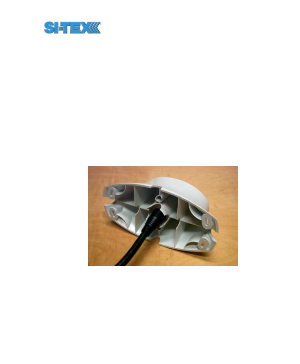
2.8.1.2 Before you start
To mount the antenna on the fixed base
• Decide if you need the roll measurement, as if you do, the Antenna Array will
need to be installed orthogonal to the vessel axis. If you don’t require roll, install
the Vector PRO parallel with the vessel’s axis.
• Choose a location that meets the requirements of Section 2.5
• Using the fixed base as a template, mark and drill the mounting holes as
necessary for the mounting surface
• Alternatively, you may rail mount the Antenna Array with appropriate hardware
2.8.1.3 Routing the cable
To install the Vector PRO using the fixed base, insert either end of the
power / data cable through the center of the fixed base as shown in the
following two figures.
Figure 2-6 Running Cable Through Fixed Base Mount
Vector PRO Reference Manual 56
Page 57

Figure 2-7 Running Cable Through Fixed Base
Align the connector keyway of the cable to the key of the connector
mounted on the Vector PRO encl osure as show in Figure. Insert the
cable-mount connector into the bulkhead connector, aligning the locking
ring at the same time.
Figure 2-8 Power / Data Cable Key and Keyway
Vector PRO Reference Manual 57
Page 58

Once inserted, rotate the ring clockwise until it locks. The locking action
is firm, but you will feel a positive ‘click’ when it has locked, as shown in
the following figure.
Figure 2-9 Connecting the Power / Data Cable to the Vector PRO
Once you have secured the connector, slide the fixed base up to the
bottom of the Vector PRO enclosure. There are two alignment keys on
top of the base that must fit into two holes of the Vector PRO enclosure.
Once you have aligned the base, use a screwdriver fitted with the
supplied Torx T20 bit to fasten the base to the enclosure using the
supplied screws. These screws self tap a thread in the blind screw
holes of the enclosure. Fasten the screws firmly, but be careful not to
strip the thread.
Note - The base is not intended to be removed and re-fastened
frequently. Frequent removal of the base from the enclosure may
result in failure of the screw hole threads. Stripped threads are
not covered under the product warranty.
The following two figures show the location of the screw holes.
Vector PRO Reference Manual 58
Page 59

Figure 2-10 Fastening the Fixed Base to the Vector PRO
Figure 2-11 Fastening the Fixed Base to the Vector PRO
Once you have fastened the fixed base to the Vector PRO enclosure
using six mounting screws, you are ready to fasten the assembly to
your mounting surface. We recommend that you use machine screws
that have an Allen Key head (hexagonal) and an “L-shaped” Allen Key,
Vector PRO Reference Manual 59
Page 60

as there may not be sufficient clearance between the bottom of the
antenna and your mounting surface to use a normal screwdriver.
Note - As we do not supply the mounting surface, you will need to
supply the appropriate fastening hardware required to complete
the installation of the Vector PRO and mount assembly.
2.8.2 Pole and Rail Mounting
You may choose to pole-mount or rail-mount the Vector PRO as
opposed to the magnetic mounting approach. The pole mount
incorporates a 1-14-UNS thread. To aid in the installation of the Vector
PRO, we have supplied a hex jam nut and washer. These are used to
secure the antenna in a particular direction without bottoming out the
system on the threaded pole. Additionally, the nut and washer
distributes forces associated with vibration onto the bottom surface of
the Vector PRO pole mount.
Caution – Do not bottom out the Vector PRO pole base on the
threaded mount. Such manner can damage the system. Use of
the jam nut and washer are mandatory for pole mounting. Any
damage resulting from not using these pieces to mount the
Vector PRO will not be covered under warranty.
2.8.2.1 Before you start
To mount the antenna on the pole mount bracket:
• Decide if you need the roll measurement, as if you do, the Antenna Array will
need to be installed orthogonal to the vessel axis. If you don’t require roll, install
the Vector PRO parallel with the ve ssel’s axis.
• Choose a location that meets the requirements of Section 2.5
• Mark and drill the mounting holes as necessary for the threaded pole as
necessary
• Alternatively, you may rail mount the Antenna Array with appropriate hardware
2.8.2.2 Pole Mount Installation and Preparation
You will need to supply the pole or rail mount hardware that you wish to
use. Once you have installed the pole or rail mount, thread the
Vector PRO Reference Manual 60
Page 61

hexagonal jam nut onto to the mount, followed by the stainless steel
washer, both supplied with the Vector PRO system. You should thread
the nut onto the mount approximately 8 to 10 full turns to provide
adequate mounting thread for the pole mount base. The following figure
illustrates this step.
Figure 2-12 Threading on the Lock Nut and Washer
2.8.2.3 Routing the Cable
When mounting the Vector PRO using the pole mount, the cable must
be run first through the center of the pole mount base (from top to
bottom), through the pole, and then through any bulkheads as needed
(the power / data connector is too large to fit through the threaded
portion of the pole mount base).
Note - Be sure to have some slack to move the cable in and out of
the pole mount by a few inches. This will allow you to connect the
cable to the Vector PRO easily.
The following three figures detail the process of routing the cable.
Vector PRO Reference Manual 61
Page 62

Figure 2-13 Running the Cable Through the Pole Base
Figure 2-14 Running the Cable Through the Pole Base
Vector PRO Reference Manual 62
Page 63

Figure 2-14 Running the Cable Through the Pole Mount
Once you have routed the cable correctly through the pole mount base
and the mounting pole, the mounting assembly should look like the
following figures.
Figure 2-15 Com pleted Cable Run
2.8.2.4 Mounting the Pole Mount Base
Thread the pole mount base onto the pole mount four to five full turns.
Vector PRO Reference Manual 63
Page 64

Figure 2-1 Threading the Pole Base onto the Mount
Ensure that there’s a gap between the lock nut and washer, and the
pole mount base as shown in the following figure. This will allow you to
orient the combination of Vector PRO and pole mount base to the
vessel.
Figure 2-17 Pole Base Threaded onto Mount
2.8.2.5 Connecting the Cable to the Vector PRO
At this point, fasten the cable to the Vector PRO connector. Notice that
the connector on the receiver enclosure has a key and that the cable-
Vector PRO Reference Manual 64
Page 65

mount co nnector has a keyway. The key and keyway need to align as
you insert the cable-mount connector into the bulkhead connector.
Note – you may have to align the locking ring on the cable-mount
connector as you insert it into the bulkhead connector, to ensure that it
seats properly.
Once the cable-mount connector has seated fully, rotate the locking ring
clockwise until it locks. You will feel the ring ‘click’ when it has locked.
The following two figures show the key, keyway, and the connection
when complete.
Figure 2-18 Power / Data Cable Key and Keyway
Vector PRO Reference Manual 65
Page 66
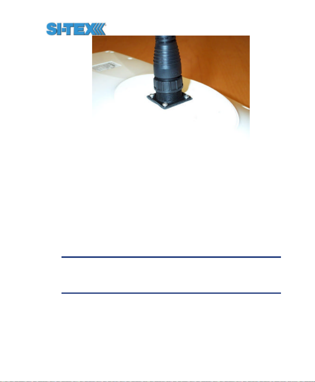
Figure 2-19 Connected Power / Data Cable
2.8.2.6 Fastening the Vector PRO to the Pole Mount Base
The next step is to fasten the Vector PRO enclosure to the pole mount
base using the supplied self-tapping screws. The following figure
illustrates this process. There are two alignment keys on top of the
base that must fit into two holes of the Vector PRO enclosure. Once
you have aligned the base, use a screwdriver fitted with the supplied
Torx T20 bit to fasten the base to the enclosure using the supplied
screws. These screws self tap a thread in the blind screw holes of the
enclosure. Fasten the screws firmly, but be careful not to strip the
thread.
Note - The base is not intended to be removed and re-fastened
frequently. Frequent removal of the base from the enclosure may
result in failure of the screw hole threads. Stripped threads are
not covered under the product warranty.
Vector PRO Reference Manual 66
Page 67

Figure 2-20 Fastening the Pole Base to the Vector PRO
The next step is to rotate the hex nut and washer up to the bottom
surface of the pole mount base. Do not tighten them at this point as you
will need to align the Vector PRO.
Figure 2-21 Threading the Lock Nut Against the Pole Base
Orient the Vector PRO using the sights on the top of the enclosure.
Using an adjustable wrench, tighten the lock nut against the Vector
Vector PRO Reference Manual 67
Page 68

PRO while ensuring accurate alignment of the antenna system.
Section 2.8.3 details the use of the alignme nt sights.
2.8.2.7 Alignment of the Vector PRO
Figure 2-22 Locking the Vector PRO once Aligned
Note - You will need to tighten the locking nut against the pole
mount base tightly. To ensure that you don’t over tighten the nut,
periodically check to see how secure the antenna system is, as
mounted on the pole. If it’s loose, tighten the lock nut further
until you can not move it.
2.8.3 Vector PRO Alignment
The top of the Vector PRO enclosure incorporates a pair of sight design
features for assisting antenna alignment. The sights will help you to
align the enclosure with respect to an important feature on your vessel.
To use the sights, center the small post on the opposite side of the
enclosure from you, within the channel made in the medallion located in
the center of the enclosure top as shown in the two following figures.
Alignment accuracy when looking through the long site is approximately
Vector PRO Reference Manual 68
Page 69
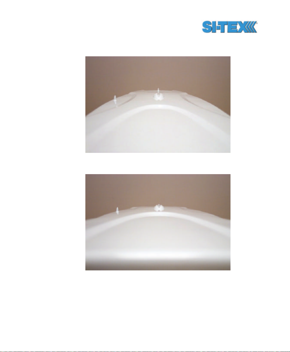
? 1?. Using the short site, alignment is approximately accurate to ?
2.5?.
Figure 2-23 Lining up the Alignment Sight
Figure 2-24 Correctly Lined -up Alignment Sight
If you have another accurate source of heading data on your vessel,
such as a gyrocompass, you may use its data to correct for a bias in
Vector PRO alignment within the Vector PRO software configuration.
Vector PRO Reference Manual 69
Page 70

Alternatively, you may wish to physically adjust the heading of the Vector
PRO so that it renders the correct heading measurement, however,
adding a software offset is an easier process.
2.9 Routing and Securing the Power / Data
Cable
The Vector PRO comes with a 15 m power / data cable. When
choosing a route for the antenna extension cable:
• Avoid running the cable in areas of excessive heat
• Keep the cable away from corrosive chemicals
• Do not run the cable through door or window jams
• Keep the cable away from rotating machinery
• Do not bend excessively or crimp the cable
• Avoid placing tension on the cable
• Secure along the cable route using plastic tie wraps as necessary
Warning - Improperly installed cables near machinery can be
dangerous.
2.10 Interfacing the Vector PRO
The Vector PRO uses a single cable for application of power and to
facilitate the input and output operations. The power cable is 15 m in
length and is terminated on the receiver end with an environmentally
sealed 18-pin connection. The opposite end is un-terminated and
requires field stripping and tinning.
Depending on your application and installation needs, you may have to
shorten this cable. If so, this is a simple matter.
However, if you require a longer cable run than 15 m, we recommend
that you bring the cable into a break-out box that incorporates terminal
strips, within the vessel. To lengthen the serial lines inside the vessel,
ensure that you use 20 gauge twisted pairs and minimize the additional
Vector PRO Reference Manual 70
Page 71

wire length. The RS-422 signal should be used for longer cable runs as
compared to the RS-232 ports, as it’s more resistant to noise and
attenuation.
When lengthening the power input leads to the Vector PRO, please
ensure that the additional voltage drop is small enough that your power
system can continue to power the system above the minimum voltage
of the system. Wire of 18 gauge or larger should also be used.
2.10.1 Power / Data Cable Pin-Out
The following table details the wire colors and their associated
functions. Each wire color is twisted with a black wire.
Table 2-1 Wire Color Interface
Wire Pairs Signal
Red Power input (8 to 40 VDC)
Black Power ground
Blue Primary GPS Port A transmit RS-232
Black with White stripe Primary GPS Port A receive RS-232
White Primary GPS Port B transmit RS-232
White with Black stripe Signal Ground
Green Primary GPS Port A transmit RS-422+
Green with White stripe Primary GPS Port A transmit RS-422-
Brown Secondary GPS Port A transmit RS-232
Brown with White stripe Secondary GPS Port A receive RS-232
Yellow Primary GPS Port B transmit RS-422+
Yellow with Black stripe Primary GPS Port B transmit RS-422-
Orange 1 pulse per second + (1 PPS +)
Orange with White stripe 1 pulse per second - (1 PPS -)
Bare Wire Drain for RF shielding – Do not
connect
Vector PRO Reference Manual 71
Page 72

Note - To identify the function of each black wire, you need to
examine which color it is twisted with. For instance, if you look at
one black wire and it’s twisted with a green wire, the function of
that black wire is ‘Primary GPS Port A transmit RS-422’.
2.10.2 Connecting to a power source
The first step to powering the Vector PRO is to terminate the wires of
the power cable as required. There are a variety of power co nnectors
and terminals on the market from which to choose, depending on your
specific requirements
Caution - do not apply a voltage higher than 40 VDC as this will
damage the receiver and void the warranty
To interface the Vector PRO power cable to the power source:
• Connect the red wire of the cable’s power input to DC positive (+)
• Connect the black wire of the cable’s power input to DC negative (-)
The Vector PRO smart antenna features reverse polarity protection to
prevent damage if the power leads are accidentally reversed. The
Vector PRO, however, does not function with reverse polarity.
Once the Vector PRO system has been installed, you’re ready to turn
the system on by applying power to it. The Vector PRO smart antenna
will start when an acceptable voltage is applied to the power leads of the
extension cable. Be careful not to provide a voltage higher than the
input range as this will damage the antenna.
2.10.3 Overview of Serial Port Interface
The Vector PRO offers position and heading data via both RS-232 and
RS-422 level serial ports. The answer of which serial port level to use
resides with the serial port level(s) supported by the other electronics
involved. You may find that the other electronics need either serial port
level or mixture of both.
The following sections describe the two serial port levels supported by
the Vector PRO.
Vector PRO Reference Manual 72
Page 73

2.10.3.1 RS-232 Interface Level
The Vector PRO features two full duplex (bi-directional) RS-232 serial
ports, one each for the primary and secondary GPS receivers. In
addition to outputting data, these ports are used for firmware upgrades.
Warning - the port for the secondary receiver may be used for
output of heading data only, and specifically, the $HEHDT and
$PSAT,HPR data messages. All other messages should not be
considered accurate. This port has been included primarily for
firmware upgrades to the secondary GPS receiver.
The primary GPS receiver full duplex serial port is Port A, however the
primary receiver also features a second half-duplex RS-232 serial port
output, Port B (an additional, programmable output data port). You may
configure Port B through Port A, so the input to Port B is not required.
In addition to supporting RS-232 signal levels, data output from both
Port A and B are available with an RS-422 interface level. Again, these
signals are outputs only as you configure the data output from Port A
and B through the RS-232 Port A input line.
Note - For general configuration of the Vector PRO, such as
adjusting the time constants, primary GPS Port A should be used.
2.10.3.2 RS-422 Interface Level
The RS-232 interface level is intended to be used with one-to-one
communications, where the serial port communicates only to one
listening device at a time. The RS-422 standard allows for one device
to communicate with many other devices simultaneously. The Vector
PRO supports both serial port levels as it’s likely that the variety of
electronic devices that you use will support one or the other, or both.
This improves the versatility of the Vector PRO.
2.10.4 Overview of Seri al Port Configuration
You may configure Port A or B of the primary GPS receiver to output
any combination of data that you wish. Port A can have a different
configuration from Port B in terms of data message output, their data
Vector PRO Reference Manual 73
Page 74

rates, and also the baud rate of the port. This allows you to configure
the ports independently, based upon your needs. For instance, if you
wish to have one generalized port and one heading-only port, you may
wish to configure Port A to have GGA, VTG, GSV, ZDA, and HDT all
output at 1 Hz over a 9600 baud rate. You may also wish to configure
Port B for HDT and ROT message output at their maximum rate of 10
Hz over a 19,200 baud rate.
The messages that you configure each port to output, and the rate of
the port will be the same for both RS-232 and RS-422 interface levels.
For instance, the RS-232 primary GPS receiver Port A and RS-422
primary GPS receiver Port A output the same data messages at the
same baud rate. If you wish to change the baud rate or messages for
the RS-422 port, this needs to be commanded through the RS-232
primary GPS Port A.
You may use both the RS-232 and the RS-422 output signals
simultaneously.
2.10.5 Interfacing to a PC Computer
PC computers typically use a DB9-male connector for RS-232 serial
port communications. To terminate either the primary GPS receiver
Port A and the secondary GPS Port A for connection to a PC serial port,
connect the wires to a DB9 female connector according to the following
two tables.
Vector PRO Reference Manual 74
Page 75

Note – If you need to upgrade the primary and receiver firmware
in the future, you will need to load it from a PC by connecting the
primary GPS Port A and secondary GPS Port B to a PC using the
DB9 interface shown below.
Table 2-2 Primary GPS Port A DB9 RS-232 Interface
Pin Wire Color Signal
2 Blue Primary GPS Receiver Transmit Data RS-
232
3 Black twisted with blue Primary GPS Receiver Receive Data RS-
232
5 Black twisted with
white
Sig. Ground
Table 2-3 Secondary GPS Port A DB9 RS-232 Interface
Pin Wire Color Signal
2 Brown Primary GPS Receiver Transmit Data RS-
232
3 Black twisted with
brown
5 Black twisted with
white
The following figure displays the numbering scheme for a DB9 socket
connector (female). The associated numbering for the plug connector
(male) on a PC computer is a mirror reflection of scheme showed in
this figure.
Primary GPS Receiver Receive Data RS232
Sig. Ground
Vector PRO Reference Manual 75
Page 76

123
4
67958
Figure 2-25 DB9 Socket Numbering
Note - For successful communications, the baud rate of the
Vector PRO serial ports must be set to match that of the devices
to which they are connected. Chapter 6 describes the baud rate
change command.
2.10.6 Interfacing to Other Devices
When interfacing to other devices, make sure that the transmit data
output from the Vector PRO is connected to the data input of the other
device. The signal grounds must also be connected.
Since RS-422 is a balanced signal with positive and negative signals
referenced to ground, ensure that you maintain the correct polarity. For
instance, when connecting the transmit data output positive signal to the
receive line of the other device, it should be connected to the receive
positive terminal. The negative transmit data signal from the Vector
PRO is then connected to the receive data negative input of the other
device.
There’s likely not much reason to connect the receive data input of the
Vector PRO to another device, unless it is able to send configuration
commands to the Vector PRO. Since the Vector PRO uses proprietary
NMEA 0183 commands for control over its configuration, the vast
majority of electronics will not be able to configure its settings unless
the other device has a terminal setting where you can manually issue
commands.
Vector PRO Reference Manual 76
Page 77

2.11 Default Parameters
This section outlines the default parameters of the Vector PRO. The
following tables provide details on the firmware types, port settings,
default NMEA messages, elevation mask, differential age mask, default
differential mode, and beacon receiver settings.
Note - Any changes you make to the Vector PRO configuration
need to be saved with the $JSAVE NMEA command in order to be
present for a subsequent power-cycle.
Table 3-2 Firmware Applications
GPS Receiver Application 1 Application 2
Primary Attitude master firmware None
Secondary Attitude secondary
firmware
Table 3-3 Default Port Settings
Port Baud Rate Data Bits Parity Stop Bit Interface Level
None
Primary Port A 19200 8 None 1 RS-232C
Primary Port B 19200 8 None 1 RS-232C (output
only)
Secondary Port
A
Primary Port A 19200 8 None 1 RS-422 (output only)
Primary Port B 19200 8 None 1 RS-422 (output only)
19200 8 None 1 RS-232C
Note - The data bits, parity, and stop bit are not adjustable. They
are fixed with an 8-n-1 configuration.
Table 3-4 Available Baud Rates
Vector PRO Reference Manual 77
Page 78

Baud Rates
4800
9600
19200
38400
Table 3-5 Default GPS NMEA Message Output
Port GPS NMEA Messages Update Rate
Primary A GGA, GSV, VTG, ZDA, HDT, ROT 1 Hz
Primary B GGA, GSV, VTG, ZDA, HDT, ROT 1 Hz
Secondary
A
No output (idle) N/A
Table 3-6 Correction Age and Elevation Mask Defaults
Max DGPS Age Elevation
Mask
1800 seconds 5?
Table 3-7 Default Differential Mode
Differential Mode
SBAS (WAAS / EGNOS)
The internal beacon module, though not the default differential
correction source, operates in full automatic mode by default as shown
in the following table.
Table 3-8 Beacon Operating Parameters
Default Differential
Mode
MSK Rate Selection
Vector PRO Reference Manual 78
Page 79

Automatic Automatic
Vector PRO Reference Manual 79
Page 80

3. Vector PRO Overview
This chapter provides a brief introduction to the Vector PRO system
and some its high-level features. The remaining chapters provide more
detailed information on the workings of the product.
As mentioned in the previous chapter, if you are new to GPS and SBAS,
we recommend that you consult Appendix B for further information on
these services and technology.
For your convenience, both the GPS and SBAS operation of the Vector
PRO feature automatic operational algorithms. However, you must
program the receiver inside the Vector PRO for which differential
service to use as it does not automatically choose one service over the
other. By default, the Vector PRO operates with SBAS corrections.
When powered, the internal GPS system performs a ‘cold start’, which
involves acquiring the available GPS satellites in view and the SBAS
and beacon differential services, if available. Acquisition of a GPS
heading is also automatic, however, you are able to force a new
heading search if needed.
If SBAS or beacon corrections are not available in your area, an external
source of RTCM SC-104 differential corrections may be used. If you
choose to use an external source of correction data, you will need to
ensure that the external source supports RS-232 and an eight data bit,
no parity, and one stop bit configuration (8-N-1) and also configure the
Vector PRO for external correction operation.
3.1 GPS
The following sections describe the general operation of the GPS
technology within the Vector PRO.
Vector PRO Reference Manual 80
Page 81

3.1.1 Satellite Tracking
The internal GPS receivers automatically search for GPS satellites,
acquire the signal, and manage the associated navigation information
required positioning and tracking. This is a hands-free mode of
operation. Satellite acquisition quality is described as a signal to noise
ratio (SNR). A higher SNR is indicative of better quality signal reception.
The primary GPS receiver supplies SNR information via $GPGSV
NMEA 0183 data messages that may be output through either Port A or
B.
3.1.2 Positioning Accuracy
The Vector PRO provides sub-meter 95% accurate positions under
ideal conditions horizontally (minimum errors). Since the Vector PRO
will be used in the real world, multipath signals and GPS signal
blockages can reduce the level of system performance. To aid in
challenging environments, the internal antennas feature a ground plane
to reduce the effects of multipath.
The performance of common GPS systems is affected when using old
correction data. Blockage of signals from SBAS satellites is often
inevitable in real world environments, as are weak beacon signals or a
noisy beacon spectrum. The COAST feature of the Vector PRO
provides solace from obstruction of SBAS services and intermittent
beacon reception for up to 30 to 40 minutes, depending on the amount
of tolerable performance drift. After 30 minutes, our testing has shown
that the Vector PRO. This feature operates by default and the COAST
time is adjusted by setting the maximum differential age as needed.
COAST is discussed in further detail in Section 3.4.
For example, if you wish to shorten this time period in order to minimize
the effect of the divergence between COAST modeling and the true
errors, the maximum COAST age can be changed to 10 minutes (600
seconds) with the following command: $JDIFF,600<CR><LF>.
The estimated positioning precision is accessible through the use of
NMEA 0183 command responses as described in Chapter 6 (The GST
NMEA data message). As the receiver is not able to determine
Vector PRO Reference Manual 81
Page 82

accuracy with respect to a known location in real time (this is
traditionally performed in post -mission analyses), the precision
numbers are relative in nature and are only approximate.
3.1.3 Update Rates
The update rate of each Vector PRO NMEA message can be set
independently with a maximum that is dependant upon the message
type. Some messages have a 1 Hz maximum, for example, while
others are 5 Hz or 10 Hz. Consult Chapter 6 for further information on
individual NMEA messages.
3.2 SBAS
The following sections describe the general operation and performance
monitoring of the SBAS (WAAS, EGNOS, MSAS, and SNAS)
demodulator within the Vector PRO. SBAS are described in further
detail in Appendix A.
3.2.1 Automatic Tracking
The SBAS demodulator featured within the Vector PRO automatically
determines if your receiver can receive WAAS or EGNOS based upon
its location. This automatic tracking allows the user to focus on other
aspects of their application rather than ensuring the receiver is tracking
SBAS correctly.
The SBAS demodulator features two -channel tracking that provides an
enhanced ability to maintain acquisition on a SBAS satellite in regions
where more than one satellite is in view. This redundant tracking
approach results in more consistent acquisition of a signal when in an
area where signal blockage of either satellite is possible.
Since SBAS broadcast at L-band frequency, a line of sight to the SBAS
satellites is required in order to acquire the signal.
Vector PRO Reference Manual 82
Page 83

3.2.2 SBAS Performance
The performance of the SBAS receiver is described in terms of a bit
error rate (BER). It indicates the number of unsuccessfully decoded
symbols in a moving window of 2048 symbols. Due to the use of
forward error correction algorithms, one symbol is composed of two
bits. The BER value for both SBAS receiver channels is available in the
RD1 NMEA data message described in detail in Chapter 6.
A lower BER indicates that data is being successfully decoded with
fewer errors, providing more consistent throughput. The bit error rate
has a default, no-lock value of 500 or more. As the receiver begins to
successfully acquire the signal, it will result in a lower bit error rate. For
best operation, this value should be less than 150 and ideally less than
20.
Space-Based Augmentation Systems broadcast an ionospheric map on
a periodic basis that may take up to 5 minutes to receive upon startup.
The Vector PRO uses the GPS broadcast ionospheric model until it has
downloaded the SBAS map, which can result in lower performance as
compared to when the map has been downloaded. This will be the
case for any GPS product supporting SBAS services.
Caution – Soon after startup, when the map has been
downloaded, you may observe a position jump due to the
potential difference between the GPS ionospheric model and the
ionospheric SBAS map. To minimize the impact of this issue on
your use of the Vector PRO, you may wish to wait up to five
minutes before using the Vector PRO or issue the
$JQUERY,GUIDE<CR><LF> message to determine if the internal
GPS receiver has achieved optimum performance.
Vector PRO Reference Manual 83
Page 84

3.3 Beacon Operation
The following sect ions describe the general operation and performance
monitoring of the SBX beacon engine within the Vector PRO.
3.3.1 Tune Modes
The internal beacon sensor may be operated in either Automatic or
Manual beacon tune modes. In Automatic Beacon Search (ABS) mode,
the receiver will identify and tune to the station providing the strongest
DGPS signal. In Manual Tune mode, you specify the frequency to
which the receiver will tune. NMEA 0183 commands are used to modify
the configuration of the beacon sensor.
3.3.1.1 Automatic Beacon Search (ABS) Mode
The Vector PRO’s internal beacon sensor operates in Automatic
Beacon Search (ABS) mode by default, selecting and tuning to the most
appropriate beacon without operator intervention. The beacon receiver
uses its two independent beacon channels to identify and lock to DGPS
beacons without interrupting the continuous flow of RTCM data to the
GPS receiver.
ABS mode is ideal for navigation applications that traverse considerable
distances, eliminating the need for operator intervention when
transitioning from one beacon coverage zone to another. The beacon
module may be manually tuned, however, this requires a NMEA
command to be send to the Vector PRO as discussed in Chapter 6.
Note - We recommend that you leave the beacon receiver in the
default ABS mode unless your requirements mandate operating
with a specific beacon.
3.3.1.2 ABS Global Beacon Search
When powered for the first time in ABS mode, the beacon sensor
initiates a Global Search using both channels, examining each available
DGPS beacon frequency, and recording Signal Strength (SS)
measurements in units of dB? V to the Global Search Table. The
Vector PRO Reference Manual 84
Page 85

receiver uses these measured values to compute an average SS, noise
floor, and to sort the frequencies in descending order of SS.
The beacon receiver’s two channels cooperatively examine the
frequencies with the highest SS measurements, above the computed
noise floor, to determine the station providing the strongest RTCM
signal. The receiver's primary channel locks to the first identified DGPS
broadcast, while the second channel continues searching in the
background for superior beacon signals. If no signal is available, the
Vector PRO will initiate a fresh Global Search, continuing this cycle until
it finds a valid station.
3.3.1.3 ABS Background Beacon Search
During the Background Search, the second beacon channel examines
all frequencies at both 100 and 200 bps MSK bit rates to identify
beacons possessing superior signal quality. If a DGPS broadcast is
identified that exhibits a 2 dB stronger signal strength than that of the
primary station, the receiver will automatically switch to this beacon. No
loss of lock occurs on the primary station during the background scan.
The beacon module stores the current primary beacon in memory so
that it is available upon subsequent power-up.
3.3.1.4 Manual Tracking
In manual tune mode, you may select a specific frequency and bit rate
for the receiver to tune, or specify the frequency only, allowing the
Vector PRO to identify the correct MSK bit rate on its own. This mode
of operation is most useful when working in an area where you know the
frequency though not necessarily the MSK bit rate of the closest
beacon.
Vector PRO Reference Manual 85
Page 86

3.3.2 Receiver Performance
The Signal to Noise Ratio (SNR) best describes the Vector PRO’s
internal SBX beacon receiver performance. The SNR, measured in dB,
is the height of the signal above the noise floor. The higher the SNR,
the more successfully the beacon receiver is demodulating the signal.
You can easily monitor the SNR in the Beacon Status menu.
Table 3-1 describes the beacon receiver quality of reception with
respect to the SNR reading.
Table 3-1 Beacon Receiver Performance - SNR Reading
SNR Reception
Description
>25 Excellent 100% data throughput
20 to 25 Very Good 100% data throughput
15 to 20 Good Good data throughput up to 100%
10 to 15 Stable Moderate to good data throughput
7 to 10 Intermittent Low data throughput
<7 No Lock No data throughput
Approximate Data
Throughput
3.4 COAST™ Technology
The Vector PRO GPS technology incorporates SI -TEX COAST
technology that allows it to operate with old correction data for up to 30
to 40 minutes or more without significant accuracy degradation. The
feature’s performance is attributed to sophisticated algorithms that are
able to anticipate how errors change during a period of correction loss.
Traditional receiver technology would experience an increasing
degradation with increasing age of corrections, resulting in less than
adequate performance over a shorter period of time. COAST
technology provides more consistent positioning during periods when
signal loss occurs, thus bridging the gap to when the signal is
reacquired. This means that the Vector PRO GPS is more tolerant than
Vector PRO Reference Manual 86
Page 87

competing products to loss of SBAS or externally input RTCM SC-104
corrections.
3.5 Vector PRO Architecture
The Vector PRO is comprised of two main components - hardware and
software. This section provides a brief overview of the hardware and
software architecture of the Vector PRO receiver in order to provide
further insight into the operation of the product.
As the Vector PRO receiver supports the following services, it provides
receiving capability for each.
• GPS
• SBAS (WAAS and EGNOS)
• Beacon
3.5.1 GPS Hardware
The SI -TEX GPS engines inside the Vector PRO provide receiving
capability for GPS and SBAS correction services (including WAAS, and
EGNOS).
The GPS engines process GPS and SBAS signals simultaneously,
devoting 2 of the primary GPS engine’s 12 parallel channels to SBAS
tracking while using the remaining 10 channels for GPS. This provides
effective tracking of multiple SBAS satellites if available.
3.5.2 GPS Firmware
The software that operates the internal components of the Vector PRO
operates within internal, low-level devices and is often referred to as
firmware.
There are two types of firmware within the Vector PRO. One type of
firmware drives the on-board digital signal processors (DSP) and
another the ARM processors. Each of these types of firmware may be
upgraded in the field through either primary GPS receiver port as new
Vector PRO Reference Manual 87
Page 88

revisions become available. The secondary GPS receiver may be
upgraded through the secondary GPS receiver port.
3.5.3 GPS Applications
The ARM processor of the two GPS engines inside the Vector PRO
each support two simultaneous versions of firmware. In the case of the
Vector PRO both the first application contains the Vector heading
application. The second application is empty. The primary GPS
receiver uses master vector firmware for both applications while the
secondary uses slave vector firmware for both of its applications.
Note - As new firmware is released, to alleviate having to different
versions of heading firmware inside the primary and secondary
GPS recei ver at the time of field upgrade of firmware, both
application slots should be overwritten with the new version of
firmware.
3.5.4 Beacon Firmware
The Vector PRO’s internal beacon module incorporates its own version
of firmware that controls its operation. This firmware can be updated
independent of the Vector GPS firmware if needed through either
primary GPS Receiver port.
Vector PRO Reference Manual 88
Page 89

4. Operation
This chapter provides a brief overview of the operations of the Vector
PRO and provides an introduction its the input / output interface. This
will help you understand how to customize its configuration to meet your
needs.
4.1 Powering the Vector PRO
As described in Chapter 2, Installation, the Vector PRO is powered by
connecting the red and black power leads of the power cable to an 8 to
40 VDC power source. You may wish to use an ammeter in-line of the
power leads in order to verify that the system has been correctly
powered. Once powered, the Vector PRO will proceed through an
internal start-up sequence, however it will be ready to communicate
within a few seconds. On power-up, you will see through the
communications port the GSV message output at 1 Hz. This is another
method to confirm that the receiver is powered and communicating
correctly.
When installed such that the Vect or PRO has an unobstructed view of
the sky, it will provide a position within approximately 60 seconds from
startup. SBAS and beacon lock require approximately 30 and 60
seconds to acquire from startup, respectively.
Note - It can take up to 5 minutes for a full ionospheric map to be
received from SBAS. Optimum accuracy will be obtained once the
Vector PRO is processing corrected positions using complete
ionospheric information. This can be confirmed with the
$JQUERY,GUIDE<CR><LF> command.
4.2 Communicating with the Vector PRO
Vector PRO Reference Manual 89
Page 90

The Vector PRO features two full-duplex serial ports, one to each GPS
receiver inside the Vector PRO enclosure. In addition to the primary
GPS receiver’s full-duplex Port A, it features a second half-duplex,
output-only port (Port B) that may be configured through Port A.
The data message output from the primary GPS receiver’s Port A and B
may be configured for a mixture of NMEA 0183, binary, and RTCM SC104 data. The usual data output is only required NMEA data messages.
The output from the secondary GPS Port A is limited to heading data
only.
Note - If you require different data types to be output from the
Vector PRO simultaneously you may wish to separate the data
between two serial ports if this is more convenient.
Warning - In addition to heading information, you can turn
position-related data on, on the secondary GPS receiver’s Port B.
Please note that the position data is NOT valid and should NOT
be used. This data is accessible for factory testing only.
4.2.1 NMEA 0183 Interface
NMEA 0183 is a communications standard established by the National
Marine Electronics Association (NMEA) and provides data definitions for
a variety of navigation and related equipment. Such instruments
supported include gyrocompasses, Loran receivers, echo sounders,
GPS receivers, and more. NMEA functionality is virtually standard on all
GPS equipment available. NMEA has an ASCII character format that
allows you to read the data via terminal software on the receiving device
(if possible). Some example NMEA data from the Vector PRO follows.
$GPGGA,144049.0,5100.1325,N,11402.2729,W,1,07,1.0,1027.4,M,0,M,,0100*61
$GPVTG,308.88,T,308.88,M,0.04,N,0.08,K*42
$GPGSV,3,1,10,02,73,087,54,04,00,172,39,07,66,202,54,08,23,147,48*79
$GPGSV,3,2,10,09,23,308,54,11,26,055,54,15,00,017,45,21,02,353,45*78
$GPGSV,3,3,10,26,29,257,51,27,10,147,45,,,,,,,,*74
Depending on each manufacturer’s goals for a product, they may have
the need to combine data into custom messages, which allows them to
Vector PRO Reference Manual 90
Page 91

improve communication and programming efficiency. The standard
NMEA standard provides for manufacturers to define their own custom,
proprietary messages as required. Proprietary NMEA messages are
likely to be supported only by the specific manufacturer and partners.
The Vector PRO supports a variety standard and proprietary NMEA
messages. These messages are used to configure the Vector PRO
and also contain the required information from the system. You may
configure a selection of NMEA 0183 data messages on one port at
various update rates (each message has a maximum update rate) and
a different selection of NMEA 0183 messages with different rates on the
other port.
Chapter 6 presents information relating to the NMEA interface of the
Vector PRO. Appendix C - Resources provides contact information
should you wish to purchase a copy of the NMEA 0183 standard.
4.2.2 Binary Interface
Binary messages may be output from the Vector PRO along with NMEA
0183 data. Binary messages have a proprietary definition that likely will
require custom software support if you wish to use it. Binary message
inherently are more efficient than NMEA 0183 and would be used when
you require maximum communication efficiency. Use of binary
messages for most users is not recommended as the NMEA interface
allows you to control the operation of the Vector PRO and also receive
all necessary data regarding status and positioning information. Binary
messages are described in Chapter 7.
4.2.3 RTCM SC-104 Protocol
RTCM SC-104 is a standard that defines the data structure for
differential correction information for a variety of differential correction
applications. It has been developed by the Radio Technical
Commission for Maritime services (RTCM) and has become an
industry standard for communication of correction information. RTCM
is a binary data protocol and is not readable via a terminal program. It
appears as ‘garbage’ data on-screen since it is a binary format and not
Vector PRO Reference Manual 91
Page 92

ASCII text. The following is an example of how the RTCM data appears
on-screen.
mRMP@PJfeUtNsmMFM{nVtIOTDbA^xGh~kDH`_FdW_yqLRryrDuhc
B\@}N`ozbSD@O^}nrGqkeTlpLLrYpDqAsrLRrQN{zW|uW@H`z]~a
GxWYt@I`_FxW_qqLRryrDCikA\@Cj]DE]|E@w_mlroMNjkKOsmMF
M{PWDwW@HVEbA^xGhLJQH`_F`W_aNsmMFM[WVLA\@S}amz@ilIuP
qx~_IZhTCpLLrYpdP@kOsmMFM[kVDHwVGbA^P{WWuNt_SW_yMsmM
nqdrhcC\@sE^ZfC@}vJmNGAHJVhTCqLRryrdviStW@H_GbA^P{wx
u[K
RTCM has various levels of detail, however the highest level is the
message. RTCM defines numerous messages that contain specific
information. The Vector PRO processes the C/A code for positioning
and does not support more advanced methods of differential such as
real-time kinematic (RTK) positioning that uses different RTCM
message types. Considering this fact, the following RTCM messages
are important for use with the Vector PRO.
• Type 1 and Type 9 messages, both of which contain similar information.
These two messages contain pseudorange corrections and range rate
corrections to each GPS satellite.
• The Type 2 message contains delta differential corrections that are used when
the remote receive r is using a different satellite navigation message than used by
the base station.
• The Type 5 message contains GPS constellation health information used for
improving tracking performance of a GPS receiver
• The Type 6 message contains null information, and is broadcast so that a
beacon receiver demodulating the data from the broadcast does not lose lock
when the beacon station has no new data to transmit.
Note - RTCM is a local area data standard. This means that when
positioning with correction input to the Vector PRO from an
external source or outputting corrections from the Vector PRO to
another GPS receiver, performance will degrade as a function of
distance from the base station. The additional degradation will
depend on the difference in observed orbit and ionospheric
errors between the reference station and the remote unit. A
general rule of thumb would be an additional 1 m error per 100
Vector PRO Reference Manual 92
Page 93

miles. This error is often seen as a bias in positioning, resulting
in a position offset. The scatter of the receiver is likely to remain
close to constant.
The RTCM SC-104 data output by the Vector PRO is converted from
the RTCM SC-159 data broadcast by SBAS.
Appendix C - Resources contains the contact information should you
wish to purchase a copy of the RTCM SC-104 specification.
4.3 Configuring the Vector PRO
All aspects of Vector PRO operation should be configured through the
primary GPS Port A with the use of NMEA 0183 commands. These
commands are described in the Chapter 6. The following items are
user-configurable only through the primary GPS receiver).
• NMEA 0183 message interface
• Tilt aiding
• Tilt Sensor calibration
• Magnetic aiding
• Magnetometer calibration
• Gyro aiding
• Time constants
• Level operation
• Heading compensation
• Configuration for pitch or roll
• Antenna separation
• Elevation mask
• Differential timeout
• Baud rates
4.4 Configuring the Data Message Output
The Vector PRO primary GPS receiver features two serial port outputs
referred to as A and B. GPS data messages for both ports are easily
configured by sending NMEA commands to the Vector PRO receiver
through Port A (the output of Port B can be configured through A). The
Vector PRO Reference Manual 93
Page 94

$JASC NMEA message discussed in Chapter 6 in details allows you to
turn messages on and off as you require.
4.4.1 This Port and the Other Port
When interfacing to Port A for the sake of turning data messages on or
off on Port B, Port B is referred to as the ‘Other’ port.
For example, if you are communicating with the Vector PRO Port A, and
wish to turn the GPGGA message on at an update rate of 5 Hz on Port
B, the following command would be used.
$JASC,GPGGA,5,OTHER<CR><LF>
If you wish to turn the GPGGA message on at 5 Hz on Port A, you would
issue the following command.
$JASC,GPGGA,5<CR><LF>
Consult Chapter 6 for more information on NMEA messages.
Vector PRO Reference Manual 94
Page 95

5. PocketMAX Utility
PocketMAX is a freely available Windows PocketPC utility designed for
use with CSI Wireless SLX and SX -1 based products, including the
Vector PRO. As this utility was not designed specifically for any one
product alone, it supports features not offered by every product, such as
tracking of the OmniSTAR differential service and display of our Vector
product’s true heading, however, the interface may be used for all I/O
operations.
This software offers you the following flexibility:
• Tune your beacon and WAAS receivers
• Monitor beacon and WAAS reception
• Configure GPS message output and port settings
• Configure and monitor heading, time constants, etc.
• Record various types of data
PocketMAX runs on any PDA with PocketPC 2000, 2002, or 2003. CSI
offers two different executables, one labeled PocketPC 2002, which
works on both 2000 and 2002 operating platforms and one labeled
PocketPC 2003, which works on the 2003 platform. You must have the
corresponding cable for your PDA to connect to a serial port on your
product. If you don’t have the latest version of PocketMAX, you can
download it from the CSI Wireless website.
www.csi-wireless.com
For a detailed discussion on the PocketMAX software, please refer to
the PocketMAX Manual, also available for download from the CSI
Wireless website.
Caution – It is important to note that when you are using
PocketMAX, the program is doing many operations behind the
scenes. This includes modifying the data output from the serial
port as the program require, which is screen dependant. When
you close PocketMAX, it will give you a message confirming the
Vector PRO Reference Manual 95
Page 96

current settings. It will then ask you if you want to proceed and
save these settings or go back and change them. Once you have
the settings configured properly for you, it is imperative to let the
program close completely on its own before you disconnect or
power down the receiver. This may take up to 10 seconds. If this
is not performed, the receiver will not be configured as you feel it
should, and can output a mixture of binary and NMEA data.
6. NMEA 0183 Messages
This chapter identifies the selection of standard and proprietary NMEA
0183 messages for the Vector PRO receiver.
Note – All NMEA commands must be sent through the primary
GPS Port A RS-232 port. From this port, you can configure the
settings of the Vector PRO and also the data messages output
from primary GPS Port A and B. The secondary GPS may be
configured for HDT and HPR message output only, using
appropriate commands.
6.1 NMEA Message Elements
NMEA 0183 messages have a common structure, consisting of a
message header, data fields, checksum, and carriage return/line feed
message terminator. An example NMEA sentence follows.
$XXYYY,zzz,zzz,zzz…*xx<CR><LF>
The components of this generic NMEA message example are displayed
in the following table.
Vector PRO Reference Manual 96
Page 97

Table6-1 NMEA Message Elements
Element Description
$ Message header character
XX NMEA Talker field. GP indicates a GPS
talker
YYY Type of GPS NMEA Message
zzz Variable Length Message Fields
*xx Checksum
<CR> Carriage Return
<LF> Line Feed
Null, or empty fields occur when no information is available for that field.
6.2 PocketMAX
CSI Wireless offers a configuration program designed for Windows
PocketPC software that runs on PocketPC 2000, 2002 and 2003
platforms. It can be used to configure and monitor your differential
source, GPS messages and it also records various types of data. It is
available for download from CSI’s website. This utility is discussed in
the PocketMAX Manual and a screen-shot is shown in the following
figure.
Caution – It is important to note that when you are using
PocketMAX, the program is doing many operations behind the
scenes. This includes modifying the data output from the serial
port as the program require, which is screen dependant. When
you close PocketMAX, it will give you a message confirming the
current set tings. It will then ask you if you want to proceed and
save these settings or go back and change them. Once you have
the settings configured properly for you, it is imperative to let the
program close completely on its own before you disconnect or
power down the receiver. This may take up to 10 seconds. If this
is not performed, the receiver will not be configured as you feel it
should, and can output a mixture of binary and NMEA data.
Vector PRO Reference Manual 97
Page 98
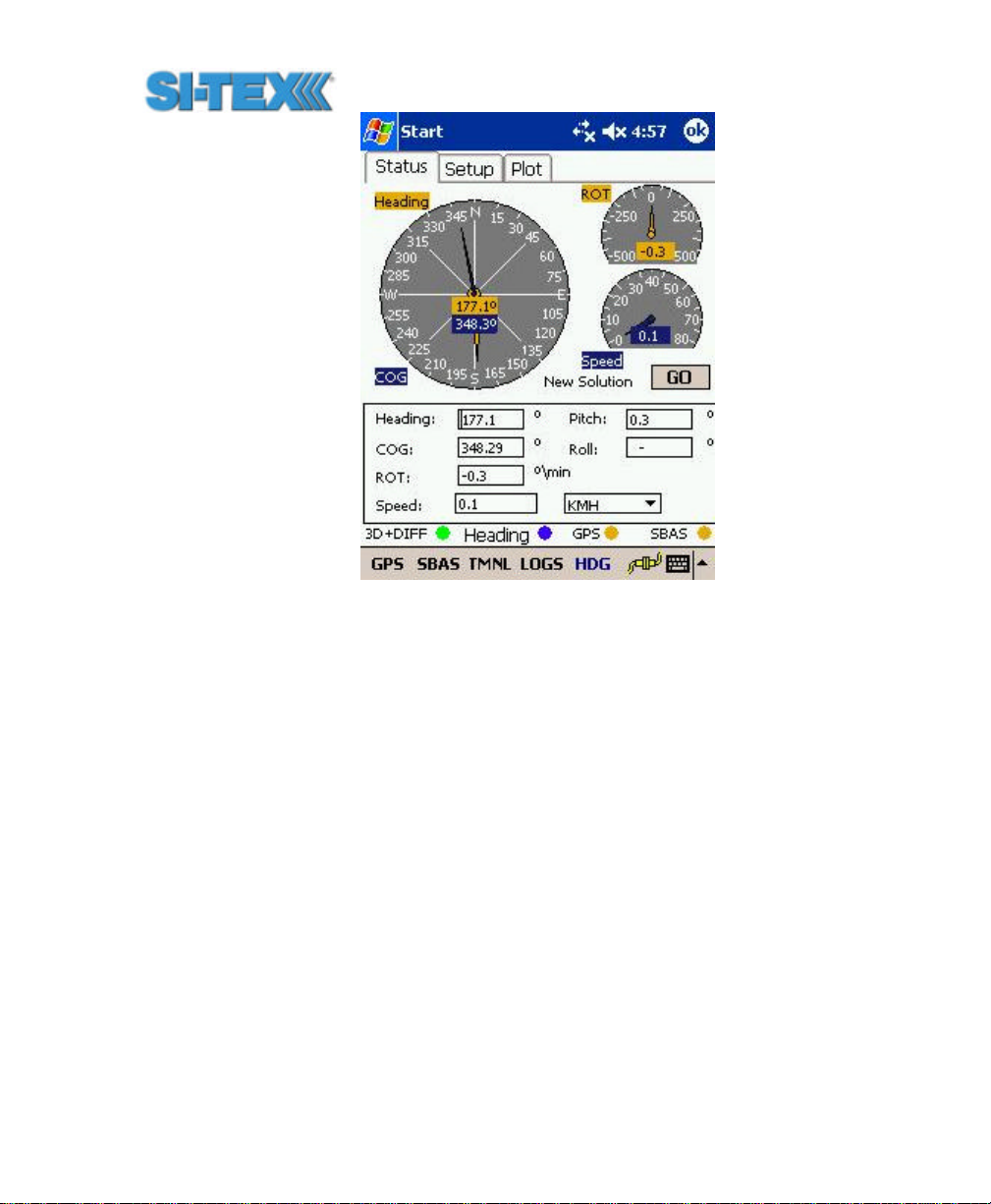
Figure 6-1 PocketMAX Screen Capture
6.3 General Commands
This section presents various commands relating to the general
operation and configuration of the Vector PRO.
The following table provides a brief description of the general
commands supported by the Vector PRO.
Vector PRO Reference Manual 98
Page 99

Table 6-1 General Commands
Message Description
$JASC,Dx Command to turn on diagnostic information.
$JAIR This is a command to place the receiver into ‘AIR’ mode where the
receiver will respond better to the high dynamics associated with
airborne applications.
$JASC,VIRTUAL This command is used to output RTCM data fed into the other port, through
the current port
$JASC,RTCM This command is used to output RTCM data from the SBAS demodulator
$JALT This command is used to set the altitude aiding mode of the Vector PRO
$JAPP This command is used to query the current applications and also choose
the current application.
$JBAUD Baud rate change command for the Vector PRO.
$JCONN Virtual circuit command used to interface to the internal beacon receiver
or communicate with the menu system microprocessor.
$JDIFF This command is used to set the differential mode.
$JK This command is used to subscribe certain features of use of the Vector
PRO.
$JPOS This command is used to provide the Vector PRO with a seed position to
acquire a SBAS signal more quickly upon start-up. This is not normally
needed.
$JQUERY,GUIDE This command is used to poll the Vector PRO for its opinion on whether or
not it is providing suitable accuracy after the both SBAS and GPS have
been acquired (up to 5 min)
$JRESET This command is used to reset the configuration of the Vector PRO.
$JSAVE This command is used to save the configuration of the Vector PRO.
$JSHOW This command is used to query the Vector PRO for its configuration.
$JT This command is used to poll the Vector PRO for its receiver type
$JBIN This command is used to turn on the various binary messages supported
by the Vector PRO
$JI This command is used to get information from the Vector PRO such as its
serial number and firmware version information
The following subsections provide detailed information relating to the
use of each command.
Vector PRO Reference Manual 99
Page 100

Note - Please ensure that you save any changes that you wish to
survive beyond the current power-up by using the $JSAVE
command and wait for the ‘$> Save Complete’ response.
6.3.1 $JASC,D1
This command allows you to adjust the output of the RD1 diagnostic
information message from the Vector PRO.
This command has the following structure.
$JASC,D1,r[,OTHER]<CR><LF>
Currently, only the RD1 message is currently defined, with x = 1. The
message status variable ‘r’ may be one of the following values.
r Description
0 ON
1 OFF
When the ‘,OTHER’ data field is specified (without the square brack ets),
this command will enact a change in the RD1 message on the other
port.
6.3.2 $JAIR
This command allows you to place the primary GPS engine within the
Vector PRO into AIR mode HIGH, where the receiver is optimized for
the high dynamic environment associated with airborne platforms. JAIR
defaults to normal (NORM) and this setting is recommended for most
applications. Turning AIR mode on to HIGH is not recommended for
Vector PRO operation.
The format of this command follows.
$JAIR,r<CR><LF>
Where feature status variable, ‘r’, may be one of the following values.
Vector PRO Reference Manual 100
 Loading...