

Si-tex SVS-760F,SVS-760C,SVS-760CF Operation Manual
- 1 -
SVS-760F FISHFINDER
OPERATIONS MANUAL
- 2 -
WARNING
Always follow this safety instruction to prevent death or injury.
CAUTION
Follow this safety instruction to avoid possible injury or
damage to your property.
Symbol “△” is a CAUTION or WARNING label indicating the
safety instruction.
WARNING
This symbol is an Electrical Shock WARNING label.
Symbol is an instruction that you must not violate.
(This symbol instructs NOT to disassemble the system
components)
Symbol is an operation instruction that you must follow.
(This symbol shows the main power OFF instruction.)
- 3 -
WARNING <For System Operators>
Always follow this instruction to prevent death or personal injury.
Turn power
off
During
abnormality.
If smoke or a small of burning occurs, a fire or
an electrical short circuit may result. Turn the
power switch OFF and shut down the power
supply immediately. Never try to repair the
system yourself. Call for service.
Do not open
Cabinet.
High voltage exists in the instrument. Contact
with voltage may cause possible injury or death.
Do not touch
back
side of the
equipment.
Harmful line voltage is present on back side of
the equipment. Never try to touch back side
while power is turned on.
Avoid
excessive
shock
to display
unit.
The LCD display module contains a liquid. Do
not apply any mechanical shock to the display.
If the display broken, liquid may leak and injure
your skin and eyes.
Do not use
with poor
ventilation.
If you cover this unit or use in an enclosed
place, it may malfunction or become damaged
as a result of overheating. Use only where there
is sufficient ventilation.

- 4 -
Installation Cautions <For service Personnel>
Follow installation instructions to avoid personal injury and system
malfunction.
Installation in
rigid location.
Mount your SVS-760 on a rigid frame or base to prevent
your unit from working loose.
Use correct
Installation
materials.
Use the installation materials provided in the standard
accessory pack only. If you use hardware of insufficient
strength, your system may loosen causing damaged.
Keep away from
direct sunlight.
Keep your system out of direct sunlight as it may
become damaged by overheating.
Keep away from
water.
Take care not to get water on or in your unit as it may be
damaged and/or cause an electrical shock.
Keep away from
heat source.
Keep your system away from other heat source as it may
malfunction, be damaged, or burn.
Use correct
power source.
Operate your system within the specified power voltage.
An incorrect power supply may cause

- 5 -
Maintenance Cautions<For Maintenance Personnel>
Use the following safety precaution internal inspection.
Discharge
capacitors.
High voltage may be retained in the capacitors if the
high-tension circuit several minutes after you have
turned the power switch off.
Check that power
is OFF
To prevent an electrical injury due to erroneous power
switching, make sure that the main power supply and
the system power switch are both in the off position.
Additionally, attach a safety label showing that service
is in progress.
Avoid EMI.
Take care not to damage the ESDs (Electrostatic
Sensitive Devices) by static electricity from carpet and
cloths.
Avoid dust.
Wear a safety mask so as not to breath in dust during
inspection or cleaning inside your system instruments.
- 6 -
Operation Notes <For operators>
Observe the following operation notes, otherwise the system failure or
deterioration can result. And periodical inspection and maintenance are required
for keeping the system in an optimum condition.
Backup important
data.
The waypoint and other registered data may become
unreadable by unexpected failure. We recommend
recording this data separately.
Use correct
transducer only.
If you use incorrect transducer, the transmitter circuit
may be damaged due to a matching error. Consult is
for system information.
Check transducer
Connection before
power on
Do not turn the power switch ON if the transducer is
disconnected or if it is not inserted into the water. If
done, the transducer or transmitter circuit may be
damaged.
Always clean the
transducer
Since transducer performance can drop due to
accumulated bottom growth, keep the transducer
clean. Never paint transducer surface.
Transducer must
be installed by
authorized
personnel.
Consult us for transducer installation by authorized
personnel.
WARNING
This product is designed to assist a navigation.
When you are sailing, use the certified chart from the
Government or IMO.
- 7 -
SVS-760 Fishfinder System
CAUTION
The SVS-760 Color LCD Fishfider Systems employs the latest in proven technology to provide
accurate fish & bottom information. The Plotter functions of SVS-760 are totally dependent upon the
capability of the navigation source to provide accurate position information. This device is only an aid
to navigation. It should be used in conjunction with all other navigation accuracy. For safety, always
resolve any uncertainty before continuing navigation.
There is no direct relationship between the color of water areas and their depth. The navigator shall
always query the area for depth information and use the official paper chart.
CAUTION
The performance of LCD displays are degraded by continuous direct exposure to ultraviolet rays.
Locate your SVS-760 Display away from direct sunlight. When not in use. Keep the display covered.
DISPLAY BREAKAGE WARNING
The LCD display module contains a liquid. If the display is broken and the liquid contacts your skin,
wash it off immediately in running water for 15 minutes. If the liquid contacts your eyes, immediately
flush your eyes with running water for 15 minutes. Contact a physician if any abnormal symptom is
experienced.

- 8 -
Welcome
Thank you for purchasing the SVS-760 from Si-Tex.
The SVS-760 is a premium multifunction Fish Finder System. SVS-760 front panel keyboard and its
wide screen viewing area make placement easy. Although SVS-760 offers many advanced features,
operation is simplified through the use of popup menus similar to those found on personal computers.
The SI-TEX SVS-760 Color LCD Fishfider System opens a new chapter of performance and
integration in Fishfinder system display and management. Whether you are a Cruiser or Sport
fisherman or both, SVS-760 gives you the information you need.
Features of the SVS-760
Comprised of a display unit and a dual frequency transducer.
The main features of the SVS-760 are
▶ A large 7” Direct Sunlight Viewable High Definition LCD Display, in a vertical format to provide
maximum sonar resolution! 480 x 800 pixels.
▶ Fishfinder offer’s Superior fish detection and bottom discrimination using the new SI-TEX All Digital
Sounder System.
▶ Instantly adapts to changing seabed and water conditions providing fully automatic “hands free”
operation.
▶ A Powerful best in class 600 watt dual frequency 50/200Khz transceiver.
▶ Digital technology eliminates unwanted noise and provides the clearest images possible at all
times.
▶ Multiple Display Modes: Normal (Single or Dual Freq.), Bottom Zoom, Bottom Lock, Shift, Split
Screens, GPS Position, Waypoint Steering, Navigation Highway.
▶ Auto & Manual Range & Gain Controls, Each Frequency can be independently controlled! Also,
Auto & Manual Shift.

- 9 -
Features of the SVS-760
▶ 10 Page Screen Capture Memory allows you to take Snap Shots of the Fish Finder Screen and
save them to memory.
▶ 10 Event point memory allows you to instantly save a Fishing location and compute your course
steering info back to the spot.
▶ Waterproof to IPX6 International Standard
▶ Very easy to operate, with front panel knobs for Gain and STC, Simple Menu Format, and all
controls labeled in plain English.
▶ New White Line / Black Line Bottom Discriminator .
▶ Fish Symbols
▶ Depth Alarm, Sea Temperature Alarm, Fish Alarm
▶ Standard equipment includes Snap on Sun Cover.
- 10 -
Fishfinder System
Introduction
The SVS-760 is a premium multifunction command and control center. SVS-760 front panel keyboard
and its wide screen with wide viewing area make placement easy. Although SVS-760 offers many
advanced features, operation is simplified through the use of popup menus similar to those found on
personal computers.
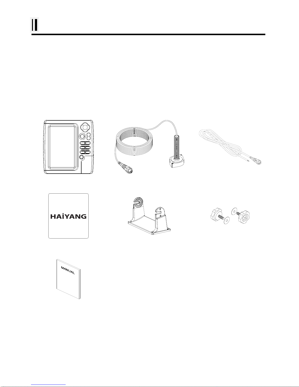
Standard Equipment Configuration List
Display unit
Transducer(option)
Power cable
Protector
Mounting Bracket
Knobs
Manual

- 11 -
Fishfinder system
Keypad
KEY
Description
[Cursor
Key]
With MENU: Choosing the menu
Without MENU: Choosing the frequency
(50/200KHz)
[GAIN]
&
[ENTER]
Button:
Enter when menu table on the screen
Rotary:
Adjustment of gain level with turning.
[+] &[-]
Setting up the depth range, when depth range
sets “manual range”.
[MENU]
One step: Quick menu is displayed.
Two step: Main menu is displayed.
[MODE]
Setting up Fishfinder mode
[FUNC]
Setting up Using Frequently key function
[EVENT]
Choose the Active,Waypoint, setup Nav or
capture functions for using one function.
[VRM]
Press the VRM key, and show the bar for the
depth range.
[CANCEL]
Return to the previous display, or canceled the
set-up.
[PWR/BRT]

- 12 -
Fishfinder system
How to use [Power/Brightness]
▶ Press [PWR/BRT]
1.Use PWR:
To turn off the power, keep pressing the [BRT/PWR] until the end of counting.
2.Use BRT:
Press [BRT/PWR] shortly and the brightness can be controlled. Use the arrow keys [←][→]of the
cursor to control the brightness and the contrast.
3. Use day/night mode
Press [BRT/PWR] shortly and change mode. Use the arrow keys [↓][↑] of the cursor to change mode.
Choosing the frequency on the dual
▶ Press [↑][↓]
You can see the red color is moving with the up and the down. In the active frequency in the red, it’s
on operation.
Choose the Gain & STC
▶ Press [←][→]
You can see the red color is moving with the right and the left. In the active Gain & STC in the red, it’s
on operation.
Auto / Manual Gain
▶ Press [ENTER]
Press the key changes Auto Gain / Manual Gain.
(* Setting is available individually)
Set Gain
▶ Tune [GAIN]
Turn to the left, the gain level will be decreasing. Turn to the right, the gain level will be increasing.
(It is applied Auto Gain Adjustment, when the mode sets “Auto gain mode”)

- 13 -
Fishfinder system
Plastic
<Front>
<Rear>
7 inch Color LCD
Keypad
Knob
Mounting Bracket
Connector
- 14 -
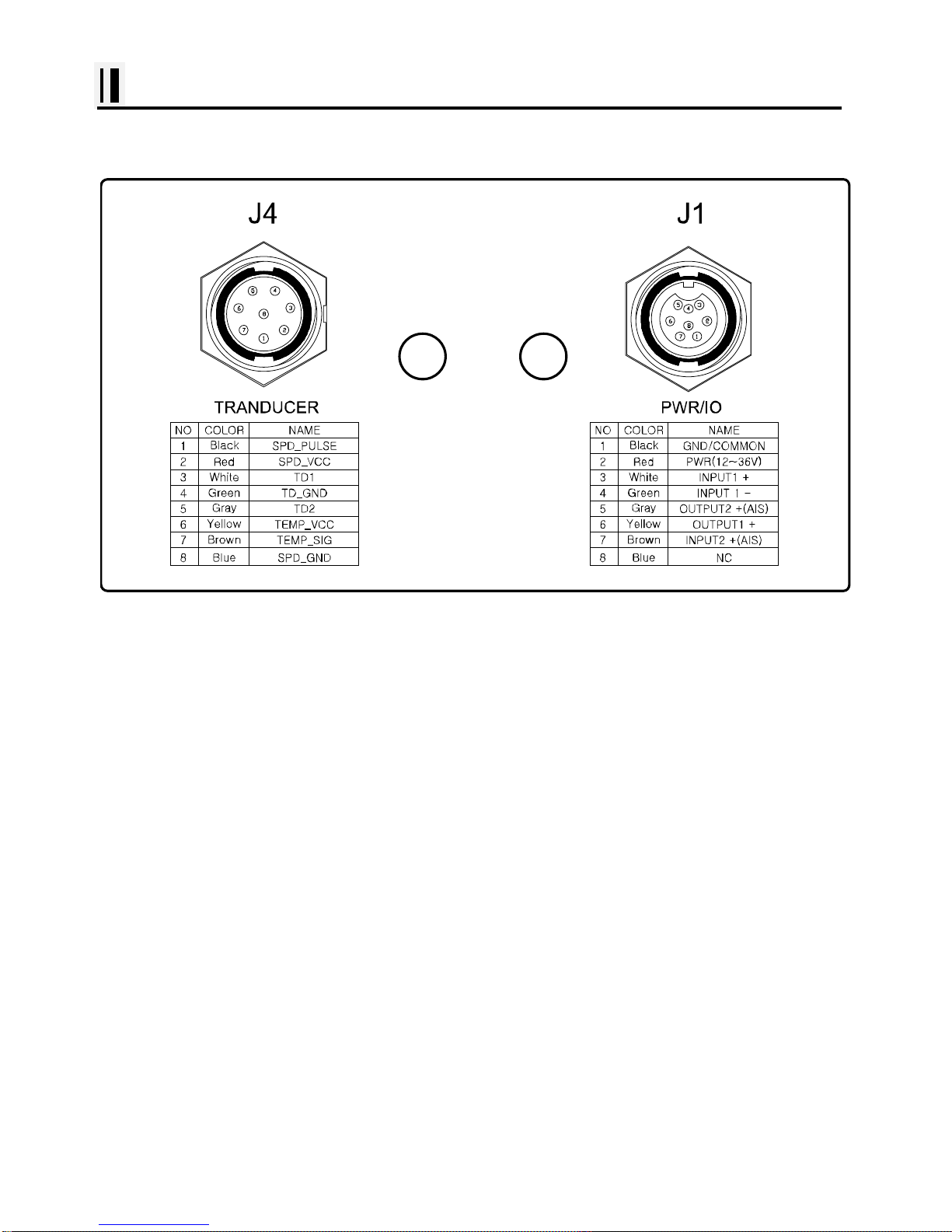
Fishfinder system
SPEC of the connectors (Plastic)

- 15 -
- 16 -
SVS-760 Introduction
Fishfinder - How it works-
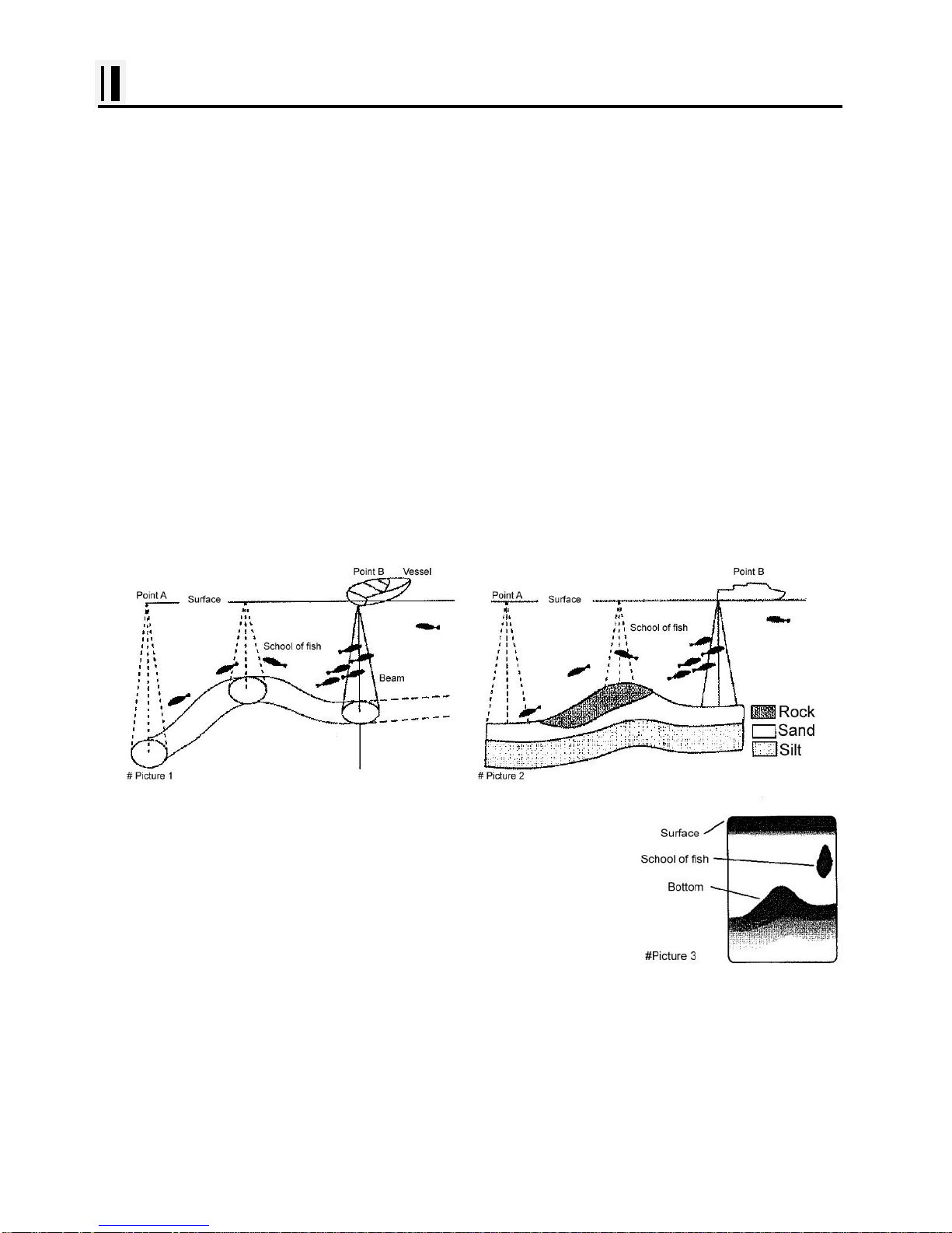
The SVS-760 echo sounder consists of a transceiver display unit and a dual frequency transducer.
An electronic signal pulse is generated in the transmitter section of the display unit. When coupled to
the transducer, this signal is converted into an ultrasonic signal and is transmitted toward the bottom.
The signal travels through the water until it strikes an object or the bottom. It is reflected back , hits the
transducer surface, and is reconverted into an electronic signal by the transducer. Then it is amplified
in the receiver section, processed in the main logic section, and displayed, as an image on a LCD
screen. (Picture 3)
When your boat travels from point A to point B as shown in Picture 1, the beam of the transducer
installed on your boat shown a cross-sectional view in the water.
Picture 2 indicates a cutaway view under the water when your boat moves from A to point B.
The screen shows the latest scan data at its right position. After the next
scan, the previous data is moved to the left and the latest scan data is
shown at the right position. When your boat moves from point A to point B,
the screen shows the scan data as shown in Picture 3.

- 17 -
Installation of the SVS-760
A careful installation will assure maximum performance from your new SVS-760.
Display Unit Location
Select a location for your Display unit that provides easy viewing from all likely operator’s positions.
The display unit is designed to be mounted on either a console or from an overhead surface. The
Display unit is also designed for flush mounting using six threaded holes on the rear panel. Locate the
display in an area with protection from the elements and avoid direct sunlight on the viewing window.
Also, consider access to the rear panel of the unit for connecting power and cables to the various
remote sensors. The mounting surface must be flat and solid to support the unit and prevent vibration.
There should be access to the inside of the surface to permit through bolt fastening for the mounting
bracket.
Display Unit Installation
Temporarily install the mounting bracket on the SVS-760 display unit and place the unit at the selected
location.
CAUTION
The Display unit is unstable when the mounting bracket is not secured. Hold the unit in place
at all times.
Check the suitability of the location and make any adjustments. When all is satisfactory, use the holes
in the mounting bracket as a guide and mark the holes locations on the mounting surface.

- 18 -
Installation
Drill a 1/4 in. diameter hole at each marked location. Mount the Display unit bracket using bolts
through the mounting surface. Place large flat washers on the opposite side of the mounting surface
from the bracket and then install lock washers and nuts. Tighten securely.
Install the display unit into the mounting bracket. Check alignment and operation of the pivots and
security of the mounting. Make any adjustments necessary to prevent binding and assure even
meshing of the pivot locking washers. It is advised to remove the display unit and store it in a safe
place to prevent damage during the rest of the installation process.
Power Connection
Power is supplied to the Fishfinder Unit through a connector on the rear panel of the display unit.
Route the power cable from the Fishfinder Unit location to the ship’s power distribution panel.
Connect the black wire to a battery negative (-) terminal of the power panel.
Connect the white wire to a fused battery positive (+) terminal of the power panel ( 12 to 24 Vdc
nominal). If a fused terminal is not available, install an in-line fuse holder.
Transducer Connection
There are many transducers available which may be used to expand the capabilities of the SVS-760
Fishfinder Unit. Connectors for these accessories are provided on the rear panel of the Fishfinder Unit.
See table on following page for list of optional transducers
 Loading...