

Page 1
SI-TEX MARINE ELECTRONICS INC
#800 - 11001 Roosevelt Blvd
St. Petersburg, Florida 33716
Phone (727) 576-5995
INSTALLATION and OPERATION MANUAL
SI-TEX SP-70 AND SP-80 AUTOPILOTS
Addendum 1
Wiring the Control Unit & Compass
(New Cable Colour Codes)
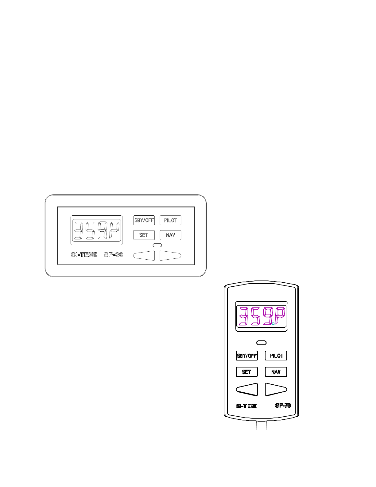
SP-70 AUTOPILOT
SP-80 AUTOPILOT
Document PN 29010049 V1.2
Addendum 1: Wiring the Control Unit & Compass 1
Page 2

SI-TEX SP-70 & SP-80 Autopilot Systems
Introduction
There is an alternate new cable type for the SP-80 Control Unit cable and the Fluxgate
Compass cable. This cable has a different colour code than the original cable type,
although it is otherwise identical.
As well, there is now an alternate SP-70 Control Unit Receptacle cable, with a different
colour code than the original cable.
Starting with systems manufactured in the Summer of 2009, either the original or the
alternate type of cable may be used, for any of the items above.
As a result, the wiring information for the SP-70 Control Unit Receptacle cable, the
SP-80 Control Unit and the Fluxgate Compass, in the Installation & Operation manual
(PN 20910049, version 1.2, April 2004) must be revised.
Please use the next two pages of this Addendum, instead of pages 37 & 38 in the
current manual.
Document PN 29010049 V1.2
Addendum 1: Wiring the Control Unit & Compass 1
Page 3

SI-TEX SP-70 & SP-80 Autopilot Systems
Right Side, Cable 1 (Control Unit) to J6
Note: There is an extra wire that is not used, in the Receptacle & Control Unit
cables; the wire is yellow on the original cable, brown on the alternate cable.
Right Side Connections
Pull all of the terminal strips from the right
hand end of the Processor.
Note that there is an empty socket that
does not have a terminal strip. When you
replace the terminal strips, do not
accidentally place one into the empty
socket!
Pass the cables numbered "1", "2" and
"3" through the watertight glands on the
right end cap, and then connect each
cable’s wires to the terminal strips, as
shown in the diagram above & those on
the following pages:
• Right Side, Cable 1 (Control Unit) to
J6
• Right Side, Cable 2 (Compass) to J6
• Right Side, Cable 3 (Rudder
Feedback) to J7
Caution: there are some differences in
the colour codes of the cable types that
can be used for Cable 1 (the SP-70
Receptacle, or the SP-80 Control Unit),
and Cable 2 (the Fluxgate Compass).
Pay attention to the colours shown in the
wiring diagrams, and in the wiring table
on the next page!
Insert the bared end of the wire into the
terminal strip and fasten it there by
tightening the screw on the terminal strip.
Start from one end of the terminal strip
and work to the other in sequence.
Check your work!
Leave the strips unplugged when you are
done; they will be plugged back in when
you mount the Processor (see page 42)
Document PN 29010049 V1.2
Addendum 1: Wiring the Control Unit & Compass 37
Page 4

SI-TEX SP-70 & SP-80 Autopilot Systems
N
Or igi n al
Cable
Colours
GR E E N
RE D
BLACK
BLUE
WHI T E
YE L L O W
SHIEL D
Al t er na t e
Cable
Colours
GREE
PINK
GREY
YELLOW
WHITE
BROW N
SHI ELD
Right Side, Cable 2 (Compass) to J6
Be Careful
The entire stripped end – but no portion of the insulation – of all wires into the terminal strip
plugs must be completely inside the plugs. The stripped ends of wire must not be able to
touch each other.
Every wire must be connected to the correct terminal on its plug!
Connections For Fluxgate Compasses
Cable 2 Signal Function
J6 PIN
Original
Wire
Colours
1 SHIELD SHIELD GROUND GND
2 YELLOW BROWN COSINE
3 WHITE WHITE REF REF
4 BLUE YELLOW SINE
5 BLACK GREY DRIVE P2 N/C **
6 RED PINK DRIVE P1 N/C **
7 GREEN GREEN +12V +12V
Alternate
Wire
Colours
* If the compass reading is reversed, swap these two wires
** These wires must not be connected to any compass other than the one
supplied with the SP-70/80
Document PN 29010049 V1.2
Addendum 1: Wiring the Control Unit & Compass 38
SP-70/80
Fluxgate
Compass
Other
Compass
COSINE *
SINE *
 Loading...