

Page 1
SP-110C Autopilot
USER MANUAL
IMPORTANT: PLEASE RETAIN ON BOARD
Page 2

(This page intentionally left blank)
Page 3

Contents
Warning! 2
SP-110C Autopilot System 3
Initial Operational Settings (SP-110C) –
Without Rudder Feedback 17
Turn Ratio 18
Initial Operational Settings (SP-110CR) –
With Rudder Feedback 9
Compass Alignment 10
Rudder End Limits – Automatic Set Up
(Rudder Feedback Required) 11
Rudder End Limits – Manual Set Up
Main Screen Explained 22
Manual Steer Mode 22
Auto Steer Mode 23
GPS Steer Mode 24
Error Messages 25
(Rudder Feedback Required) 12
Rudder Ratio (Proportional Gain) 13
Rudder Sensitivity (Rudder Tolerance) 13
Error Gain (Integral Control Gain) 13
Rate of Change
(Derivative Gain Multiplier) 14
Rate of Turn (Max Turn Angle) 14
Dead Band 15
BOD Correction (GPS Mode) 15
Reverse Delay 15
Advanced Option s
(Recommended for Installers Only) 25
Steering Menu 26
Coms Menu 27
Elecom Menu (Compass Calibration) 27
GPS Menu (NMEA Corrections) 29
Factory Default 29
About 30
Setting up Your GPS Unit 30
Minimum Speed 16
Backlight Bright 16
Wind Mode
SP-110C Alarms 31
Definition of Terms 31
(Requires MWV NMEA Data Input) 16
Testing Procedure 32
Trouble Shooting 33
Declaration of Conformity 34
Warranty 35
Additional Information 35
Block Diagram of Full System
3
Pulse Size
18
Installation of System Components
3
Rate Tolerance
19
Display Unit
4
Period
19
Compass
5
Rate of Turn (Max Rudder Angle)
19
Rudder Feedback Unit
6
Dead Band
19
Rudder Feedback / GPS Wiring Diagrams
8
BOD Correction (GPS Mode)
20
GPS Wiring Connections
8
Reverse Delay
20
Hydraulic Reversing Motor Connection
9
Minimum Speed (Requires GPS SOG)
21
Mechanical Reversing Motor Connection
9
Backlight Bright
21
Solenoid Connection
9
Wind Mode
(Requires MWV NMEA Data Input) 21
Page 4

Warning!
• THE AUTOPILOT IS A
NAVIGATIONAL AID; AN
ADEQUATE WATCH MUST BE
MAINTAINED AT ALL TIMES
WHEN AUTOPILOT IS IN USE.
• THE AUTOPILOT MUST BE
PLACED IN MANUAL MODE
WHEN THE VESSEL IS
STATIONARY AS THE SYSTEM
WILL CONTINUE TO DRIVE THE
RUDDER TO THE END OF ITS
TRAVEL AND DAMAGE TO THE
SYSTEM MAY RESULT.
• IT IS STRONGLY
RECOMMENDED THAT THE
AUTOPILOT NOT BE USED
WHILE NAVIGATING IN
RESTRICTED WATERWAYS
AS WATER CURRENTS,
WIND CHANGES OR RADIO
TRANSMITTER INTERFERENCE
CAN ENDANGER YOUR OWN OR
OTHER VESSELS.
• IF A GPS IS CONNECTED TO
THE SYSTEM, THE AUTO MODE
WILL NOT ENGAGE BELOW A
SPEED OF ONE KNOT AND WILL
DISENGAGE FROM AUTO WHEN
THE VESSEL SLOWS TO ONE
KNOT.
2 of 35
SI-TEX SP-110C
Page 5

SP-110C Autopilot
System
The SP-110C Autopilot control
system comprises the following units:
• SP-110C display and control head.
• SI-TEX E-compass
• Rudder Feedback Unit
(SP-110CR only).
In addition the SP-110C has to be
connected to a drive unit which
controls the rudder actuator system
in order to complete the full autopilot
system. The actuator system
provides the physical movement to
the rudder responding to the direction
of control signals provided by the SP110C. A rudder actuator system
comprises one of the following:
• Hydraulic system with helm pump
and ram
• Mechanical steering system
The autopilot should be connected
to a:
• Reversing motor / pump set
connected into the existing
hydraulic steering system; or
• Continuously running Hydraulic
Pump with solenoid control.
• Reversing mechanical drive unit
connected to the existing steering
mechanism
Block Diagram of full system
*Dashed line (RFU) only for
applicable for SP-110CR.
The SP-110C display provides full
control of the autopilot system and
indicates different modes for heading,
course to steer and rudder angle.
The system requires a supply voltage
of 12-24 Volts DC (Up to 29V During
Charging)
Installation of System
Components
Ensure you have all the components
of the autopilot.
Tools required:
• Screwdrivers – flat blade and
Phillips head
• Side cutting pliers
• Wire strippers
• Spanners (various) or
adjustable spanner
• 70mm hole saw
• Power drill + assortment of drill bits
• Multi meter (DVM)
• Ancillaries such as tape,
connecting block, screws, cable
ties, etc.
SI-TEX SP-110C 3 of 35
Page 6
Access for wiring must be provided.
Cables have to be run to the power
switchboard, display, compass,
rudder feedback (if fitted) and
drive unit.
All wiring should be kept as far as
possible from radio aerials and aerial
cables to prevent interference to
the radio and to prevent transmitted
signals from the radio influencing
the SP-110C.
The compass must be mounted a
minimum distance of 1 metre from
any boat compass, radios, speakers
or other products with magnetic
properties to avoid interference. The
SP-110C must have a direct
connection to power supply via a 15
amp circuit breaker or a 15 amp
fused circuit and an isolating switch.
Display Unit
Position:
The SP-110C Head unit should be
mounted in a position accessible to
the steering position and protected
from direct rain or salt water.
• Select a dry position
• For in dash mounting cut a 70mm
(2.5”) hole (an optional mounting
bracket is available and may be
used for display mounting – see
your supplier)
• Drill mounting screw holes
• Mount the display using screws
supplied (304 SS – 6G)
• Fit dome plugs to cover screws
• Ensure motor (yellow) and clutch
(green) wires are not exposed
before connecting power to the
SP-110C
• Connect red wire to + 12 volts DC
(Positive)
• Connect black wire to - 12 volts DC
(Negative)
Figure 1: (below) Wiring Diagram
4 of 35
SI-TEX SP-110C
Page 7
Compass
Take care when handling the
compass as it is a sensitive piece of
equipment. The compass position
is the most important item in the
installation of the autopilot. Good
course holding is dependent on the
compass being free from magnetic
interference and exces s ive r olling
or pitching.
Position:
• Select a dry position free from
magnetic interference. (Note other
side of bulkheads and deck heads
for magnetic type objects)
• Avoid positions near radios,
speakers, aerial cables or any other
current carrying cable.
• Mount the compass horizontally
with the arrow (bow) pointing in the
same direction as the boat’s bow.
Use non-magnetic screws (316
grade stainless steel)
• Run cable to SP-110C display
position (keep away from other
cables)
• Connect compass cable to
SP-110C compass socket
Compass Mounting:
Vessel Bow
Figure 2: E-Compass V3
Figure 3: E-Compass V4
SI-TEX SP-110C 5 of 35
Page 8
Rudder Feedback Unit
*Only for SP-110CR version.
The SP-110CR Autopilot is
supplied with an RFU (rudder
feedback unit), which provides to
the pilot a precise position of the
boat rudder.
Position:
• Refer to diagram on page 7
• Mount rudder feedback adjacent to
the tiller (rudder feedback movement
must copy the angular movement
of the tiller). Use mounting bracket
if required
• Note markings on the rudder
feedback unit. P & S indicate the
required movement of the tiller
for course correction (Port and
Starboard).
• Rudder feedback is mounted
with shaft uppermost
• Fit snap lock swivel joint to rudder
feedback arm
• Fit link block to tiller arm
• Fit link arm from rudder feedback
to tiller – adjust for correct angle
• Route cable to SP-110CR
display position
• Connect rudder feedback cable
to SP-110CR rudder socket
• When installation is complete,
slowly move the steering by hand
to ensure:
a)
The direction indicated on the
top of the RFU is correct
b)
No undue mechanical strain
is placed on the feedback or
linkage
Figure 4: Rudder feedback unit.
Page 9

6 of 35
SI-TEX SP-110C
Page 10
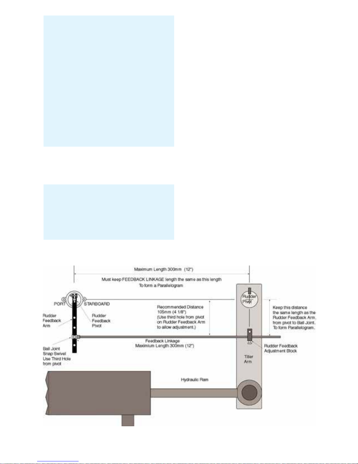
Rudder Feedback Installation
Diagram
Figure 5:
SI-TEX SP-110C 7 of 35
Note: The rudder feedback unit is
water resistant. However, if it is to
be mounted in a wet position, some
protection should be provided to
ensure the unit does not become
excessively expose d or submersed
in water.
The rudder feedback unit may be
mounted upside down, in which
case the blue and red wires in the
cable must be reversed (yellow
wire in cable is not used in the
feedback).
Note: The rudder feedback is
factory aligned. The arm should
not be removed or loosened on the
shaft as this will affect the “O” ring
seal.
Page 11

Rudder Feedback / GPS Wiring Diagrams
Pin connections from rear of plug, solder connection side.
Pin 1 has adjacent dot. See Figure 6.
Pin 1 5V Rudder Feedback Supply
Pin 2 Rudder Feedback Wiper Return
Pin 3 0V Rudder Feedback Supply
Pin 4 TX Data (heading information)
Pin 5 + GPS Input (Positive)
Pin 6 - GPS Input (Negative)
Figure 6: Pin Assignments
SP-110C View
GPS Wiring Connections
Pin connections from rear of plug, solder connection side.
Pin 5 + GPS Input (Positive) - white wir e
Pin 6 - GPS Input (Return) - green wir e
For GPS navigation, connect the GPS unit via the two wires coming from
the back of the rudder feedback plug on the SP-110C displ a y unit.
Heading Data out is also available
Pin 4 + Heading Data Out (Positive) - red wire
Pin 3 - Heading Data Out (Negative) - blue wire (0 volt line)
8 of 35
SI-TEX SP-110C
Note: For information on connecting different
brands of GPS units, refer to the relevant GPS manual
Note: Pin locations are relative to pin 1 which
always has a dot adjacent.
Page 12

Hydraulic Reversing Motor
Connection
• Route suitable two core cable
(10 amp min) from motor to
SP-110C display
• Connect motor cable to the yellow
and yellow/black motor wires at
SP-110C
Mechanical Reversing Motor
Connection
• Route suitable four core cable
(10 amp min) from motor to
SP-110C display
• Connect motor wires to the yellow
and yellow/black motor wires at
SP-110C
• Connect one clutch wire to green
wire at SP-110C
• Connect second clutch wire to
+ 12 VDC voltage supply
• Go to into Settings Page 2, and
choose solenoid negative for
common negative or solenoid
positive for common positive
Initial Operational
Settings (SP-110CR) –
With Rudder Feedback
The initial set up of the SP-110C
is done onc e the system
installation is complete and
power has been connected to
the SP-110C display control. The
set up can be done automatically
or manually Automatic installation
set up
determines the output polarity for motor
direction and rudder limit setting.
The installation procedure is
designed to work on a rudder speed
of approx. 8 to 20 seconds hard over
to hard over. The process may fail
with faster or slower rudder
movement in which case the manual
set up should be used.
The maximum r udder trave l wil l be
set to approx. 33º e ach sid e in the
automatic set up.
Solenoid Connection
• Route suitable two core cable (5
Amp min.) from solenoids to SP110C
• Connect solenoid connection to
either positive or negative supply.
• Fit diodes (eg 1N4007) to
solenoids. Ensure the line on the
diode is on the positive terminal on
solenoid.
SI-TEX SP-110C 9 of 35
Note: If a linear hydraulic drive
is used, the connections are for
mechanical drive.
Note: If the manual set procedure
is used, motor direction and both
rudder end limits must be set.
Notes:
Motor direction can be checked
with SP-110C in MANU AL by
pressing ◄ or ► once power has
been connected to the SP-110C
Page 13

Compass Alignment
Your electronic com pas s may not be
aligned correctly due to mounting etc.
SP-110C can adjust the heading
reading from the compass to account
for alignment error.
You will require an alternative
heading reference to set the
adjustment (eg. Magnetic compass /
GPS plotter etc)
To commence:
• Switch power on to SP-110C
• Wait until Main Screen is displayed
(Figure 8)
• Hold MODE button, Settings Page
1 will appear (Figure 9)
• Press MODE and AUTO buttons at
the same time. Install Options 1 will
appear (Figure 10)
• Scroll down to COMPASS
ALIGNMENT using the ► Button
• Press AUTO button to edit
• The large Orange number is the
raw heading reading from the
electronic compass
• The large Green number is the
Corrected Compass (Aligned)
heading.
• Press ◄ or ► to change the
Corrected Compass heading so it
matches your alternative reference
(Figure 7)
• Press MODE to exit back to
Settings Page 1
• Press MODE to exit back to Main
Screen
• The live compass reading on the
main screen will be the Corrected
Compass heading.
• All steering will use the Corrected
Compass heading.
Figure 7: Press ◄ or ► to
change the Corrected Compass
heading so it matches your
alternative reference
10 of 35
SI-TEX SP-110C
Page 14

Rudder End Limits –
Automatic Set up
(Rudder Feedback required)
To commence:
• Switch power on to SP-110C
• Wait until Main Screen is displayed
(Figure 8)
• Hold MODE button, Settings Page
1 will appear (Figure 9)
• Press MODE and AUT O buttons at
the same time. Install Options 1 will
appear (Figure 10)
• Press AUTO button to enter
Steering Menu (Settings Page 2)
Figure 11.
• Ensure USE RFU is set to YES
• Scroll down to END LIMIT AUTO
using the ► Button
• Press AUTO button to start set up
(Figure 12)
• Process will take between 20 and
60 seconds to complete depending
on the speed of the motor
• If process is successful display will
show CAL OK SAVING….
• Press either MODE to cancel the
installation process, display will
show ABORT CALIBRATION
• If CAL ERROR is displayed an
error has occurred
• Check the drive output is
connected and rudder feedback
is moving
• Check rudder feedback installation
• To Exit menu, press MODE button
Figure 8: Example Main Screen
(Manual Steer Mode)
Figure 9: Example Settings Page 1
Figure 10: Example Install Opt ions 1
SI-TEX SP-110C 11 of 35
Page 15

Figure 11: Example Settings Page 2
Rudder End Limits –
Manual Set up
(Rudder Feedback required)
• Switch power on to SP-110C
• Wait until Main Screen is displayed
(Figure 8)
• Hold MODE button, Settings Page
1 will appear (Figure 9)
• Press MODE and AUT O buttons at
the same time. Install Options 1 will
appear (Figure 10)
• Press AUTO button to enter
Steering Menu (Settings Page 2)
Figure 11.
• Ensure USE RFU is set to YES
• Scroll down to END LIMIT PORT
using the ► Button
• Press AUTO button to enter Port
Adjustment (Figure 12)
• Press ◄ to move rudder to Port
• Press ► to move rudder to
starboard
• If direction is incorrect, reverse
the yellow wires, or change SWAP
OUTPUT in previous menu.
• Move to Port Limit, press AUTO
button (Figure 13)
• Press AUTO again to save, or
MODE to abort.
• Scroll down to END LIMIT STBD
using the ► Button
• Press AUTO button to enter
Starboard Adjustment
• Move to Starboard Limit, press
AUTO button
• Press AUTO again to save, or
MODE to abort.
• To Exit menu, press MODE button
Figure 12: Port Limit Adjustment
Figure 13: Save Limits Confirmation
Screen
12 of 35
SI-TEX SP-110C
Page 16

Rudder Ratio
(Proportional Gain)
Factory default setting is 3 and
should only be altered during
sea trials
• With Main Screen displayed
(Figure 8)
• Hold MODE button, Settings
Page 1 will appear (Figure 9)
• Press AUTO to edit RUDDER
RATIO
• Press ► to increase setting
(larger rudder ratio)
• Press ◄ to decrease setting
(smaller rudder ratio)
• Press MODE to return to
Settings Page 1
• Press MODE to return to
Main Screen
Rudder Sensitivity
(Rudder Tolerance)
Factory default setting is 4 and
should only be altered during
sea trials
• With Main Screen displayed
(Figure 8)
• Hold MODE button, Settings
Page 1 will appear (Figure 9)
• Press ► to scroll down to
RUDDER SENSE
• Press AUTO to edit
RUDDER SENSE
• Press ► to increase setting
(more tolerance to the rudder
position error)
• Press ◄ to decrease setting
(less tolerance to the r udder
position error)
• Press MODE to return to
Settings Page 1
• Press MODE to return to
Main Screen
Error Gain
(Integral Control Gain)
Factory default setting is 5 and
should only be altered during
sea trials
• With Main Screen displayed
(Figure 8)
• Hold MODE button, Settings
Page 1 will appear (Figure 9)
• Press ► to scroll down to
ERROR GAIN
• Press AUTO to edit ERROR GAIN
SI-TEX SP-110C 13 of 35
Note: Increasing the Rudder
Sensitivity too high can cause
vessel wandering
Note: A value of 1 signifies the
minimum amount of applied rudder.
When the rudder setting is too
low, vessel track will be slow i.e.:
understeer due to too little rudder
applied. A value of 20 signifies
the maximum amount of applied
rudder. When the rudder setting is
too high, vessel track will be rapid
i.e.: oversteer due to too much
rudder applied.
Page 17

• Press ► to increase setting
(more turn to target heading)
• Press ◄ to decrease setting
(less turn to target heading)
• Press MODE to return to
Settings Page 1
• Press MODE to return to
Main Screen
Rate of Change
(Derivative Gain Multiplier)
Factory default setting is 3 and
should only be altered during
sea trials
• With Main Screen displayed
(Figure 8)
• Hold MODE button, Settings
Page 1 will appear (Figure 9)
• Press ► to scroll down to RATE
OF CHANGE
• Press AUTO to edit RATE
OF CHANGE
• Press ► to increase setting (more
dampening of error)
• Press ◄ to decrease setting (less
dampening of error)
• Press MODE to return to Settings
Page 1
• Press MODE to return to Main
Screen
Rate of Turn
(Max Turn Angle)
Factory default setting is 500°M
and should only be altered during
sea trials
• With Main Screen displayed
(Figure 8)
• Hold MODE button, Settings Page 1
will appear (Figure 9)
• Press ► to scroll down to RATE
OF TURN
• Press AUTO to edit RATE OF TURN
• Press ► to increase setting (more
attack angle)
• Press ◄ to decrease setting (less
attack angle)
• Press MODE to return to Settings
Page 1
• Press MODE to return to Main
Screen
14 of 35
SI-TEX SP-110C
Note: This limits the max turn
speed of the vessel. Reduce this
to reduce the angle of attack for
getting to target heading.
Note: Increasing Rate of Change
can help dampen Error Gain. If set
too high, vessel may never make it
to target heading.
Note: Increase Error Gain to get
on track faster. If set too high, the
vessel will overshoot the ta rget
heading.
Page 18

Dead Band
Factory default setting is 1.0° and
should only be altered during
sea trials
• With Main Screen displayed
(Figure 8)
• Hold MODE button, Settings
Page 1 will appear (Figure 9)
• Press ► to scroll down to DEAD
BAND
• Press AUTO to edit DEAD BAND
• Press ► to increase setting
(more allowance for error)
• Press ◄ to decrease setting
(less allowance for error)
• Press MODE to return to
Settings Page 1
• Press MODE to return to
Main Screen
BOD Correction
(Applies to GPS Mode only)
Factory default setting is 15 and
should only be altered during
sea trials
• With Main Screen displayed
(Figure 8)
• Hold MODE button, Settings
Page 1 will appear (Figure 9)
• Press ► to scroll down to BOD
CORRECTION
• Press AUTO to edit BOD
CORRECTION
• Press ► to increase setting
(more correction)
• Press ◄ to decrease setting
(less correction)
• Press MODE to return to Settings
Page 1
• Press MODE to return to Main
Screen
Reverse Delay
Factory default setting is 15 and
should only be altered during
sea trials
• With Main Screen displayed
(Figure 8)
• Hold MODE button, Settings
Page 1 will appear (Figure 8)
• Press ► to scroll down to
REVERSE DEL A Y
• Press AUTO to edit REVERSE
DELAY
• Press ► to increase setting
(more delay)
• Press ◄ to decrease setting
(less delay)
• Press MODE to return to
Settings Page 1
• Press MODE to return to
Main Screen
SI-TEX SP-110C 15 of 35
Note: This number increases or
decreases the angle of attack from
a GPS / PC supplied BOD (Bearing
Origin to Destination) when in GPS
mode.
Note: This delay helps reduce
shock load on the rudder drive
train, as it controls the time
between direction chang es ( eg.
Port to Starboard or Starboard to
Port changes)
Note: Increase this to reduce
rudder hunting.
Page 19

Minimum Speed
(Requires GPS)
Only used when no rudder
feedback SOG installed
Factory default setting is 1.0km
and should only be altered during
sea trials
• With Main Screen displayed
(Figure 8)
• Hold MODE button, Settings
Page 1 will appear (Figure 9)
• Press ► to scroll down to
MINIMUM SPEE D
• Press AUTO to edit MINIMUM
SPEED
• Press ► to increase setting (higher
minimum speed)
• Press ◄ to decrease setting (lower
minimum speed)
• Press MODE to return to Settings
Page 1
• Press MODE to return to Main
Screen
Backlight Bright
Factory default setting is 15
(Maximum Brightness)
• With Main Screen displayed
(Figure 8)
• Hold MODE button, Settings
Page 1 will appear (Figure 9)
• Press ► to scroll down to
BACKLIGHT BRIGHT
• Press AUTO to edit BACKLIGHT
BRIGHT
• Press ► to increase setting
(Brighter screen)
• Press ◄ to decrease setting
(Darker screen)
• Press MODE to return to
Settings Page 1
• Press MODE to return to Main
Screen
Wind Mode
(Requires MWV NMEA
data input)
Factory default setting is OFF
• With Main Screen displayed
(Figure 8)
• Hold MODE button, Settings
Page 1 will appear (Figure 9)
• Press ► to scroll down to
WIND MODE
• Press AUTO to edit WIND MODE
• Press ► to enable Wind Mode
• Press ◄ to disable Wind Mode
• Press MODE to return to Settings
Page 1
• Press MODE to return to Main
Screen
16 of 35
SI-TEX SP-110C
Note: This setting is useful for
adjusting screen brightness for day
/ night or low lit areas.
Note: When Wind Mode is ON, the
SP-110C will attempt to correct for
wind effects on vessel steering.
Note: When the vessel is below
this set speed and in Auto or GPS
mode, the SP-110C will revert
back to Manual mode.
Page 20

Initial Operational
Settings (SP110C)
– Without Rudder
Feedback
The initial set up of the SP-110C
is done once the system
installation is complete and
power has been connected to the
SP-110C display control.
Figure 14: Example Main Sc reen
(Manual Steer Mode)
Figure 15: Example Settings Page 1
Figure 16: Example Install Opt ions 1
Figure 17: Example Settings Page 2
Page 21

SI-TEX SP-110C 17 of 35
Page 22

Turn Ratio
Factory default setting is 3 and
should only be altered during
sea trials
• With Main Screen displayed
(Figure 14)
• Hold MODE button, Settings Page
1 will appear (Figure 15)
• Press AUTO to edit TURN RATIO
• Press ► to increase setting (larger
turn ratio)
• Press ◄ to decrease setting
(smaller turn ratio)
• Press MODE to return to Settings
Page 1
• Press MODE to return to Main
Screen
Pulse Size
Factory default setting is 3 and
should only be altered during
sea trials
• With Main Screen displayed
(Figure 14)
• Hold MODE button, Settings
Page 1 will appear (Figure 15)
• Press ► to scroll down to
PULSE SIZE
• Press AUTO to edit PULSE SIZE
• Press ► to increase setting
(longer pulses)
• Press ◄ to decrease setting
(shorter pulses)
• Press MODE to return to Settings
Page 1
• Press MODE to return to Main
Screen
18 of 35
SI-TEX SP-110C
Note: This sets the minimum
solenoid / motor pulse length when
hunting for the heading track.
Note: A value of 1 signifies the
minimum amount of applie d rudder.
When the rudder setting is too
low, vessel track will be slow i.e.:
understeer due to too little rudder
applied.
Page 23

Rate Tolerance
Factory default setting is 15 and
should only be altered during
sea trials
• With Main Screen displayed
(Figure 14)
• Hold MODE button, Settings Page
1 will appear (Figure 15)
• Press ► to scroll down to RATE
TOLERANCE
• Press AUTO to edit RATE
TOLERANCE
• Press ► to increase setting (more
tolerance to the rate of turn error)
• Press ◄ to decrease setting (less
tolerance to the rate of turn error)
• Press MODE to return to Settings
Page 1
• Press MODE to return to Main
Screen
Rate of Turn
(Max Rudder Angle)
Factory default setting is 500°M and
should only be altered during
sea trials
• With Main Screen displayed
(Figure 14)
• Hold MODE button, Settings Page 1
will appear (Figure 15)
• Press ► to scroll down to RATE
OF TURN
• Press AUTO to edit RATE OF
TURN
• Press ► to increase setting
(more attack angle)
• Press ◄ to decrease setting
(less attack angle)
• Press MODE to return to Settings
Page 1
• Press MODE to return to Main
Screen
Period
Factory default setting is 4 and should
only be altered during sea trials
• With Main Screen displayed
(Figure 14)
• Hold MODE button, Settings Page
1 will appear (Figure 15)
• Press ► to scroll down to PERIOD
• Press AUTO to edit PERIOD
• Press ► to increase setting (longer
delay between rudder pulses)
• Press ◄ to decrease setting
(shorter delay between rudder
pulses)
• Press MODE to return to Settings
Page 1
• Press MODE to return to Main
Screen
Dead Band
Factory default setting is 1.0°
and should only be altered during
sea trials
• With Main Screen displayed
(Figure 14)
• Hold MODE button, Settings Page
1 will appear (Figure 15)
• Press ► to scroll down to DEAD
BAND
• Press AUTO to edit DEAD BAND
• Press ► to increase setting
(more allowance for error)
• Press ◄ to decrease setting
(less allowance for error)
SI-TEX SP-110C 19 of 35
Note: This limits the max turn
speed of the vessel. Reduce this
to reduce the angle of attack for
getting to target heading.
Note: Increasing the Rate
Tolerance too high can cause
vessel wandering
Page 24

• Press MODE to return to
Settings Page 1
• Press MODE to return to Main
Screen
BOD Correction
(Applies to GPS Mode only)
Factory default setting is 15 and
should only be altered during
sea trials
• With Main Screen displayed
(Figure 14)
• Hold MODE button, Settings
Page 1 will appear (Figure 15)
• Press ► to scroll down to BOD
CORRECTION
• Press AUTO to edit BOD
CORRECTION
• Press ► to increase setting
(more correction)
• Press ◄ to decrease setting
(less correction)
• Press MODE to return to Settings
Page 1
• Press MODE to return to Main
Screen
Reverse Delay
Factory default setting is 15 and
should only be altered during
sea trials
• With Main Screen displayed
(Figure 14)
• Hold MODE button, Settings Page
1 will appear (Figure 15)
• Press ► to scroll down to
REVERSE DEL A Y
• Press AUTO to edit REVERSE
DELAY
• Press ► to increase setting
(more delay)
• Press ◄ to decrease setting
(less delay)
• Press MODE to return to
Settings Page 1
• Press MODE to return to
Main Screen
20 of 35
SI-TEX SP-110C
Note: This number increases or
decreases the angle of attack from
a GPS / PC supplied BOD (Bearing
Origin to Destination) when in GPS
mode.
Note: This delay helps reduce
shock load on the rudder drive
train, as it controls the time
between direction chang es ( eg.
Port to Starboard or Starboard to
Port changes)
Note: Increase this to reduce
rudder hunting.
Page 25

Minimum Speed
(Requires GPS SOG)
Only used when no rudder
feedback installed
Factory default setting is 1.0kn
and should only be altered during
sea trials
• With Main Screen displayed
(Figure 14)
• Hold MODE button, Settings
Page 1 will appear (Figure 15)
• Press ► to scroll down to
MINIMUM SPEE D
• Press AUTO to edit MINIMUM
SPEED
• Press ► to increase setting
(higher minimum speed)
• Press ◄ to decrease setting
(lower minimum speed)
• Press MODE to return to
Settings Page 1
• Press MODE to return to Main
Screen
Backlight Bright
Factory default setting is 15
(Maximum Brightness)
• With Main Screen displayed
(Figure 14)
• Hold MODE button, Settings
Page 1 will appear (Figure 15)
• Press ► to scroll down to
BACKLIGHT BRIGHT
• Press AUTO to edit BACKLIGHT
BRIGHT
• Press ► to increase setting
(Brighter screen)
• Press ◄ to decrease setting
(Darker screen)
• Press MODE to return to Settings
Page 1
• Press MODE to return to Main
Screen
Wind Mode
(Requires MWV NMEA
data input)
Factory default setting is OFF
• With Main Screen displayed
(Figure 14)
• Hold MODE button, Settings
Page 1 will appear (Figure 15)
• Press ► to scroll down to
WIND MODE
• Press AUTO to edit WIND MODE
• Press ► to enable Wind Mode
• Press ◄ to disable Wind Mode
• Press MODE to return to Settings
Page 1
• Press MODE to return to Main
Screen
SI-TEX SP-110C 21 of 35
Note: This setting is useful for
adjusting screen brightness for day
/ night or low lit areas.
Note: When Wind Mode is ON, the
SP-110C will attempt to correct for
wind effects on vessel steering.
Note: When the vessel is below
this set speed and in Auto or GPS
mode, the SP-110C will revert
back to Manual mode.
Page 26

Main Screen Explaine d
Manual Steer Mode
The live compass heading is
displayed in the top center, as a
bar-graph below it, and in large
green numbers near the middle
of the screen.
Below the large numbers is the
current steering mode (MANUAL
STEER), or an error in red.
The live supply voltage is displayed
top right side.
If Latitude is received via NMEA
input, it will be displayed top left
If Longitude is received via NMEA
input, it will be displayed top right
If vessel speed is received via NMEA
(SOG), it will be displayed top left.
Rudder Angle is indicated by a bar
and number. The number and bar will
be red when Port side, Green when
Starboard side, and yello w when in
center at 0°
Figure 18: Example Manual Steer
Mode Main Screen. Live Compass
heading is 185°, Rudder is at center.
Press ◄ or ► buttons to move
the rudder.
Hold MODE to enter Settings
Page 1
Press AUTO to enter Auto Steer
Mode
Hold MODE and press AUTO to enter
GPS steer mode.
22 of 35
SI-TEX SP-110C
Page 27

Auto Steer Mode
The current target heading is in large
yellow numbers near the middle of
the screen.
If a yellow bar appears within the
compass bar, it indic ates current
deviation from target heading.
Target Heading is 315°, Deviation
is shown as a yellow bar within the
compass bar.
Press ◄ or ► buttons to change the
target heading.
Hold MODE to enter Settings Page 1.
Press AUTO to enter manual steer
mode.
Briefly press MODE to toggle target
heading step size between 1° and
10° (indicated in yellow brackets).
Figure 19: Example Auto Steer Mode
Main Screen. Live Compass heading
is 314°, Target Heading is 314°
Deviation is shown as a yellow bar
within the compass bar.
SI-TEX SP-110C 23 of 35
Page 28

GPS Steer Mode
The live compass heading is
displayed in the top center, as a
bar-graph below it.
If a yellow bar appears with in the
compass bar, it ind icates current
deviation from target heading.
The current target heading received
via NMEA is in large blue numbers
near the middle of the screen. If no
NMEA heading is received, it will
display the current compass heading.
Below the large numbers is the
current steering mode (GPS
HEADING), or an error in red.
The live supply voltage is displayed
top right side.
If Latitude is received via NMEA
input, it will be displayed top left
If Longitude is received via NMEA
input, it will be displayed top right
If vessel speed is received via NMEA
(SOG), it will be displayed top left.
Rudder Angle is indicated by a bar
and number. The number and bar will
be red when Port side, Green when
Starboard side, and yello w when in
center at 0°.
Hold MODE to enter Settings Page 1.
Press AUTO to enter Manual Steer
Mode.
Press ◄ or ► to adjust BOD
correction.
Figure 20: Example GPS Steer Mode
Main Screen. Live Compass heading
is 314°, Target Heading is 313°,
Deviation is shown as a yellow bar
within the compass bar.
24 of 35
SI-TEX SP-110C
Page 29

Error Messages
There are a number of possible error messages that can be displayed on
screen, in place of the current Steer Mode text.
Examples are:
MOTOR SHORT - Over current detected on motor wires
CLUTCH SHORT - Over current detected on clutch wire
ANGLE OFF COURSE - Vessel is more then 45° from Target Heading.
RUDDER AT LIMIT - Rudder has reached the set end stop
RFU DISCONNECTED - Cannot detect the rudder feedback unit
GPS – NO GPS DATA - No NMEA XTE and no BOD received
GPS – NO GPS XTE - No NMEA XTE or APB XTE or RMB XTE received
GPS – NO GPS BOD - No NMEA BOD or APB BOD received
NO XTE – SET DEST - User needs to set a destination waypoint in GPS / PC
VESSEL TOO SLOW - Vessel is too slow to maintain steering without
rudder feedback.
If the Compass is disconnected or faulty, NO COM PASS wi ll be displ a yed in
place of the compass heading, and the compass bar will disappear.
Advanced Options
(Recommended for
installers only)
There are a number of Advanced
Options, recommended for
installers only.
• With Main Screen displayed
(Figure 14)
• Hold MODE button, Settings Page
1 will appear (Figure 15)
• Press MODE and AU TO buttons at
the same time, INSTALL OPTIONS
1 should appear (see Figure 21).
• Press ► to scroll down to desired
menu, press AUTO to enter the
menu
Figure 21: Advanced Sett in gs
(Install Options 1)
SI-TEX SP-110C 25 of 35
Page 30

Steering Menu
(Recommended for
installers only)
For setup of Rudder output and
Rudder end limits (Figure 22 and
figure 23)
• USE RFU – Choose to use Rudder
Feedback or not.
• SWAP OUTPUT – Choose to
reverse the rudder output
• SOLENOID – Choose common
connection polarity when used with
solenoids.
• END LIMIT PORT – Manually set
the Port rudder limit
• END LIMIT STBD – Manually set
the Starboard rudder limit
• END LIMIT AUTO – Automatically
set rudder lim its and rudd er output
direction
Figure 22: Advanced Steer i ng Menu
(Settings Page 2), with USE RFU
enabled
Figure 23: Advanced Steer i ng Menu
(Settings Page 2), with USE RFU
disabled
Coms Menu
(Recommended for
installers only)
This menu is used to monitor live
incoming NMEA data.
• A list of NMEA data headers is
displayed. Headers in White are
being received (Figure 24).
• Press ► to scroll down to desired
header, press AUTO to view
the data.
• Press MODE to return to list
screen.
• Press MODE again to return to
Install Options 1 menu.
• Press MODE to return to Main
Screen
(See images next page)
26 of 35
SI-TEX SP-110C
Note: The set Port and Starboard
rudder limits, and live rudder
position is displayed at the bottom
of the screen (When USE RFU set
to YES)
Page 31

Figure 24: Example Coms Menu
(COMS DIAGNOSTICS)
Figure 25: Example live HDT
(Heading True) compass data
Elecom Menu
(Compass Calibration)
To carry out this procedure the boat
must be in open waters and be able
to safely turn clockwise through 360º.
The purpose of this is to compensate
for local magnetic influences of the
vessel.
• From the Install Options 1 menu,
use ► to scroll down to ELECOM
MENU and press AUTO button.
Press ► to confirm or MODE to
exit (Figure 26)
• When the screen prompts to TURN
THE BOAT, Start turning the boat
clockwise at low speed, hold the
turn constant.
• When calibration is complete, the
screen returns to Install Options
1 menu.
Figure 26: Confirmatio n scr een
SI-TEX SP-110C 27 of 35
Page 32

Figure 27: SP-110C sending
calibration command to Elecom, and
waiting for a response
Figure 28: Start turning the boat
clockwise at low speed, hold the turn.
Figure 29: Elecom calibrat i on
successful
Figure 30: Elecom not commun ic ati ng,
or does not support Calibration mode.
Figure 31: Calibration failed, vessel
Figure 32: Calibration failed, vessel
turning too slow turning too fast.
28 of 35
SI-TEX SP-110C
Page 33

GPS Menu
(NMEA corrections)
These adjustments can be used to
improve tracking when in GPS mode.
• From the Install Options 1 menu,
use ► to scroll down to GPS
MENU and press AUTO button to
enter (Figure 33)
• Scroll to desired setting using ◄
or ►, and press AUTO to modify
setting
• Modify setting using ◄ or ►, and
press MODE to return to list of
settings.
Figure 33: Example GPS Menu
(Track Settings)
Factory Default
This will reset all settings to default
values,
• From the Install Options 1 menu,
use ► to scroll down to FACTORY
DEFAULT, press AUTO button to
enter (Figure 34)
• Follow on-screen instructions
Figure 34: Factory Default (Factory
Reset) warning screen
Figure 35: Factory Default complete.
SI-TEX SP-110C 29 of 35
Page 34

About
This displays information about the
build of the SP-110C,
• From the Install Options 1 menu,
use ► to scroll down to ABOUT,
press AUTO button to enter
(Figure 36)
• Press any button to exit back to
Install Options 1 menu.
Figure 36: About screen example.
Setting up your GPS Uni t
Because there are a great variet y
of GPS units that will work with this
autopilot, the followin g is a guide only.
For more information, consult your
GPS manual.
The GPS unit must be set up to
output “NMEA 0183” data at 4800
baud on a pair of wires, which are
connected to the SP-110C unit via
the rudder feedback connector. The
data generated must include at least
one of the following:
• The APA sentence.
• The APB sentence.
• The BOD and XTE sentences.
• If only the XTE data sentence is
available, the pilot can steer in a
restricted manner only. (See later in
this section.**)
The GPS unit must be programmed
and activated to navigate to a
waypoint, or to follow a line joining
two or more waypoints (called a
route). This unit should then send
information to the autopilot from
which can be calculated the courseto-steer.
Under the following conditions:
• Several waypoints are linked
together into a single route,
• The GPS unit is set and capable of
“auto-sequence” between them,
• An “arrival zone” of more than
0.05 NM (Nautical Miles) is set so
that the GPS can detect when the
vessel has reached a waypoint ;
then the SP-110C will be able to
steer from each waypoint to the
next without intervention.
30 of 35
SI-TEX SP-110C
Page 35

** If only the XTE information is
available from your GPS unit then
your vessel must be on track, and
heading in the correct direction,
before engaging the GPS unit.
The “auto sequence” feature is not
available in this instance.
SP-110C Alarms
A number of conditions will cause
alarms to sound and an alarm
message to flash on the display
Off Course Alarm
In AUTO mode an audible alarm of 3
“beeps” per second will sound when
boat heading is greater than 45º from
the desired course. A red message
will also be displayed on the screen
GPS Alarm
In GPS steering mode an audible
alarm of 1 “beep” per second will
sound when no GPS data is received
by the SP-110C. A red message will
also be displayed on the screen.
Compass Alarm
If there is no reading from a compass,
or no HDM / HDT data incoming, an
audible alarm of 1 “beep” per halfsecond will sound. A red message will
also be displayed on the screen.
Low Speed Alarm
When used without a rudder
feedback (RFU), if the vessel speed
goes below the low speed threshold
set in the settings, an audible alarm
of 1 “beep” per second will sound.
A red message will also be displayed
on the screen.
Definition of Terms
SP-110C Display: The
operational control unit with colour
display and push buttons.
Heading: This is the magnetic
direction of the vessel at the
current time.
Course-to-steer: The dir ection
(heading) which t he auto pil ot is
attempting to maintain.
SI-TEX SP-110C 31 of 35
Note: Prior to engaging GPS
mode, a route or destination must
be programmed and selected in
the GPS for the Autopilot to follow.
Page 36

Testing Proce dure
Initial Inspection and Testing
1. Confirm power to be connected is the required DC voltage.
2. Power Supply 12V-24V DC is available.
3. Ensure polarity of the voltage supply is correct.
4. All electrical connections are correct.
5. Loose cables are clipped or tied up.
Dockside Tests
1. Turn steering wheel fully clockwise and visually check that
moving (mechanical) parts do not foul;
2. Repeat step 1 for anti-clockwise.
3. Return Steering to centre.
4. Switch on SP-110C Autopilot system.
5. Press arrow button to operate steering in that direction.
6. Check that rudder moves in correct direction.
7. Check Rudder direction follows change request.
8. Check Course change provides sufficient Rudder movement.
9. Check compass heading display on SP-110C.
10. Return steering to centre.
32 of 35
SI-TEX SP-110C
Page 37

Trouble Shooting
SP-110C Display is completely
black
• Check power is available:
12V-24VDC
• Check boat master switch for
autopilot
• Check circuit breaker (if applicable)
• Check in-line fuse of SP-
110C red wire
• Check all wiring connections
SP-110C Does not move
rudder when AUTO is
selected
• Confirm SP-110C display is
showing
compass heading information.
• Check voltage is present at the
SP-110C motor connections
(Yellow and yellow with black
stripe) when AUTO is selected
and a course change applied.
• Confirm that the supply voltage is
12V-24VDC (Red and Black).
• Check all motor and clutch wiring
• Check motor brushes
• Check the hydraulic system:
1. Ensure there is sufficient
hydraulic fluid.
2. Purge the system of possible air
locks / contamination.
3. Ensure that any flow restricting
valves are not completely closed.
4. Check all connections for leaks.
SP-110C Display will not
change from MANUAL STEER
mode.
• Vessel speed may be below the set
threshold, and USE RFU set to NO.
• Check speed setting in settings
page 1 is greater than one
• Vessel must be moving forward at
or higher then that set speed.
SP-110C Does not
follow waypoint route
• Check GPS plotter waypoint setting
• Check GPS HEADING mode
selected on SP-110C
• Check alarm status of SP-110C
• Ensure that the GPS unit has the
correct magnetic correction factor.
• Check SP-110C compass
alignment and possible magnetic
interference
No GPS Data Alarm
• Check wiring of the GPS to the
SP-110C unit.
• Check sentence in GPS unit for
correct data output (APA/APB/BOD
& XTE)
• Check route is set up or selected in
the GPS unit
• Check location fix at the GPS unit.
Page 38

SI-TEX SP-110C 33 of 35
Customer Service
If you encounter problems during the installation or operation of this
product, or cannot find the information you need, please contact Sitex
Customer Service.
The contact numbers and e-mail address for Sitex Customer Service are:
Sitex Main Office…….………..+1-631-996-2690
Sitex Fax..………………….…..+1-631-996-2693
Sitex Customer Support E-mail address: customerservice@si-tex.com
Sitex Main Office Address:
25 Enterprise Zone Drive, Ste 2
Riverhead, NY 11901
Technical Support is available from 9:00 AM to 5:00 PM Eastern
Standard Time, Monday through Friday.
Page 39

Declaration of
Conformity
(MANUFACTURERS
DECLARATION)
Manufacturer:
SI-TEX
Electronics
Declares under our sole responsibility
that the products:
SP-110C Display, Rudder Feedback
Unit, Compass, all units
interconnected with nec es sary cables
and external connections as a system
to which this declaration relates, is in
conformity with Standard(s):
EN60945/1997
CEI IEC945/1996
For SI-TEX Marine Electronics
12
th
October 2017
Allen Schneider
34 of 35
SI-TEX SP-110C
Page 40

CERTIFICATE OF LIMITED WARRANTY
Providing you present valid proof of purchase, SI-TEX Marine Electronics warrants all parts of
each
new product against defects in material and workmanship under normal use and will repair or
exchange
any parts proven to be defective at no charge for a period of two years from the original date of
purchase, except as provided below under Limited Warranty Exceptions.
Defects will be corrected dur ing nor mal wor k ing ho urs by an authorize d SI -TEX Marine
Electronics
dealer, service center , or at the SI-TEX offic e in River he ad, NY. There will be no charge for
repair labor
for a period of one year from the date of purchase, except as provided below under Limited
Warranty
Exceptions. This Warra nty and Pro of of Purcha s e must be made available to the authorized SITEX
Marine Electronics serv ice location or dealer at the time of service.
LIMITED WARRANTY EXCE PTI ONS
SI-TEX Marine Electronics will not be respo ns ib le for equip ment w hic h has been s ubje c ted to
water
or lightning damage, acc ident, abuse, or misuse, nor any equipment on which the serial number
has been
removed, altered, or mutilated . SI-TEX Marine Electronics assumes no respons ib i lity fo r damage
incurred during installa tio n. This Limited Warranty is effective only wi th res pec t to the or iginal
purchaser. Any cost associa ted w ith trans d uc er replac e m e nt, other than the cost of the
transducer itself ,
is specifically exclud e d from the Limite d Warranty.
Travel cost incurred will no t be accep ted by SI-TEX Marine Electronics
THERE ARE NO WARRANTIES WHICH EXTEND BEYOND THE DESCRIPTION ON THE FACE
HEREOF.
SPECIFIC EXCLUSIONS
Charges for overtime, stand-by, holiday, and per diem are specifically exclud ed fro m the Limited
Warranty. fuses are consum able ite m s and are not cover e d by this Limite d Warr a nty .
Installation workmans hip or materials, except as provided directly by SI-TEX Mar ine Electr o nics
are not covered by this Limited Warranty .
SI-TEX Marine Electronics equipme nt, or par ts ther eo f which have been repaired or altered
except by
an authorized SI-TEX Marine Electr o nic s d e aler or servic e center are not warra nte d in any
respect.
Transducers, software updates, batteries, magnetrons and microwav e compo ne nts , are items
excluded from the two-year warranty and are covered by warranty for a period of one year for
both parts and labor.
SI-TEX Marine Electronics will not, at any time as s ume any costs or labo r c harg es for check o ut
or
external line fuse replac ement or pro b le ms not found to be at fault in the equipm e nt its e lf.
Page 41

THERE ARE NO WARRANTIES OR GUARANTEES EXPRESSED OR IMPLIED WHICH EXTEND
BEYOND THE DESCRIPTION OF THE FACE HEREOF, INCLUDING WARRANTIES OF FITNESS FOR
A PARTICULAR PURPOSE AND MERCHANTABILITY. SI-TEX MARINE ELECTRONICS HAS
NO OTHER LIABILITY TO PURCHASE FOR DIRECT OR CONSEQUENTIAL DAMAGE OR ANY
THEORY INCLUDING ABSOLUTE LIABILITY, TORT, OR CONTRACT. THIS LIMITED WARRANTY
CANNOT BE ALTERED OR MODIFIED IN ANY WAY AND SHALL BE INTERPRETED IN
ACCORDANCE
WITH THE LAWS OF THE STATE OF NEW YORK. THIS WARRANTY IS LIMITED TO THE
CONTINENTAL U.S.A., ALASKA, HAWAII, AND CANADA.
MAILING & SHIPP ING ADDRESS:
SI-TEX Marine Electronics
25 Enterprise Zone Drive, suite #2
Riverhead, NY 11901
(631) 996-2690
HOW TO OBTAIN SERVICE UNDER THIS WARRANTY
To provide greater flexibility, SI-TEX Marine Electronics gives you the option
to obtain service under the warr anty by either:
(a) Contacting an authorize d SI-TEX Mari ne Ele c tro nic s servic e statio n
(The closest service station may be found by contacting your dealer of purchase)
OR
(b) Shipping your equipment pr epaid via UPS, FED-EX or truck with insurance prepaid to SI-TEX
Marine
Electronics. at the addres s prov ided be low . SI-TEX Marine Electronics will whenever
possible, make all repairs covered by Limited Warranty within two weeks of receiving the
equipment
in New York and return the same to you, freight prep a id.
Please do not use the Mail Service due to delays in tracing lost packages.
(c) You must present a copy of your Purchase Sales Slip at the time you reque s t warr anty
service.
A product repair case can be started from the support section of our website at www.si-
tex.com
SI-TEX SP-110C 35 of 35
Page 42

 Loading...