

Page 1

MDS 1
Radome 0.9 Feet
MDS 8
Radome 1.5 Feet
MDS 9
Radome 1.8 Feet
MDS 10
Open 4 or 5 Feet
Copyright 2008 Seiwa - Hong Kong
All rights reserved. Printed in Italy. No part of this publication may be reproduced or distributed in any form or by any
means, or stored in a database or retrieval system, without prior written permission of the publisher.
User Manual
code: (D 050608e)
Page 2

Safety Precaution
HIGH VOLTAGE WARNING
Dangerously high voltages are present within the RADAR scanner unit. There are
no internal connections or adjustments necessary for installation. Only a qualified
radar service technician should remove the cover. Technicians must exercise extreme care when working inside the unit. Always remove power before removing
the cover. Some capacitors may take several minutes to discharge, even after
switching off the radar. Before touching the magnetron or any high voltage components, ground them with a clip lead.
MICROWAVE RADIATION HAZARD
The microwave energy radiated by a radar antenna is harmful to humans, especially to one’s eyes. Never look directly into an open waveguide or into the path of
radiation from an enclosed antenna. Radar and other radio frequency radiation
can upset cardiac pacemakers. If someone with a cardiac pacemaker suspects
abnormal operation, immediately turn off the equipment and move the person
away from the antenna. Turn off the radar whenever it is necessary to work on
the antenna unit or on other equipment in the beam of the radar.
MAGNETRON PREHEATING
When starting your RADAR for the first time or when restarting it after a two
month or longer non-operating period, preheat the magnetron at least 30 minutes in standby mode.
Please read through this manual before the first operation. If you have any questions, please contact the Company’s customer service or your local dealer.
4 User Manual
Page 3

Contents
Safety Precaution ................................................................................. 4
HIGH VOLTAGE WARNING ................................................................................. 4
MICROWAVE RADIATION HAZARD ......................................................................... 4
MAGNETRON PREHEATING ................................................................................. 4
About this User Manual ................................................................................. 7
INTRODUCTION ................................................................................. 7
CONVENTIONS USED ................................................................................. 8
HOW THIS USER MANUAL IS ORGANIZED ............................................................... 8
IF YOU NEED ASSISTANCE ................................................................................. 8
EQUIPMENT SUPPLIED ................................................................................. 8
1. Radar Installation ................................................................................. 9
2. Functions ............................................................................... 23
Optional Equipment ................................................................................. 8
1.1 INSTALLATION CONSIDERATIONS ................................................................... 9
1.2 PREPARE THE RADAR FOR INSTALLATION ........................................................ 9
1.3 INSTALLATION PROCEDURE ......................................................................... 10
1.4 ELECTRICAL AND DATA CONNECTIONS .......................................................... 10
1.5 CONNECTION PROCEDURE ........................................................................... 10
1.6 RADAR JUNCTION BOX CONNECTIONS ........................................................... 11
1.6.1 Jumper To Control Radar On/Off Operation ........................................... 13
1.6.1.1 Radar Powered On all the time ................................................ 13
1.6.1.2 Radar Powered On/Off Controlled by an External Switch ............. 13
1.6.1.3 Radar Power On/Off Controlled by the Chart Plotter Software ...... 13
1.6.2 Alternative Power Connection ............................................................. 13
1.6.2.1 Power Connections ................................................................ 13
1.7 SOFTWARE CONFIGURATION ........................................................................ 13
1.7.1 I/O Setup ............................................................................... 13
1.7.2 Warming Up ............................................................................... 14
1.7.3 Transmission On ............................................................................... 14
1.7.4 Radar calibration ............................................................................... 14
1.7.4.1 Heading Line ........................................................................ 14
1.7.4.2 Antenna Parking Position ....................................................... 14
1.7.4.3 Sector Transmission Off ......................................................... 15
1.7.4.4 Transmission Trigger Delay .................................................... 15
1.7.4.5 Automatic and Manual Tune ................................................... 18
Manual Tune ........................................................................ 19
Automatic Tune .................................................................... 20
1.7.4.6 Save Tuning to User C-CARD .................................................. 21
1.7.4.7 Load Tuning from User C-CARD ............................................... 21
2.1 BASIC ............................................................................... 23
2.1.1 Cross Cursor ............................................................................... 23
2.1.2 Chart Overlay ............................................................................... 23
2.1.3 Range ............................................................................... 24
2.1.4 Orientation ............................................................................... 24
2.1.5 Motion Mode ............................................................................... 24
2.1.6 Echo Trails Settings ........................................................................... 25
2.1.7 Target Expansion .............................................................................. 25
2.2 SENSITIVITY ............................................................................... 25
2.2.1 Interference Rejection ....................................................................... 25
2.2.2 Gain Adjustment ............................................................................... 25
2.2.3 STC (Sensitivity Time Constant) Adjustment ......................................... 25
2.2.4 FTC (Fast Time Constant) Adjustment .................................................. 26
2.2.5 MBS (Main Bang Suppression) Adjustment ............................................ 26
User Manual
5
Page 4

2.3 RADAR FEATURES ............................................................................... 26
2.3.1 Cursor Window ............................................................................... 26
2.3.2 Heading Marker ............................................................................... 26
2.3.3 Degree Scale ............................................................................... 27
2.3.4 Range Rings ............................................................................... 27
2.3.5 Compass Rose ............................................................................... 28
2.3.6 EBL & VRM ............................................................................... 28
2.3.6.1 Handling of EBL/VRM ............................................................. 29
2.3.7 Parallel Cursor ............................................................................... 29
2.3.8 Center Offset ............................................................................... 30
2.3.8.1 Handling of Center Offset ....................................................... 30
2.3.9 Status Bar ............................................................................... 30
2.4 CHART FEATURES ............................................................................... 31
2.4.1 Chart Overlay Mode ........................................................................... 31
2.4.2 Chart Synchronization ....................................................................... 31
2.4.3 Cursor Echo ............................................................................... 31
2.5 GUARD ZONES ............................................................................... 31
2.5.1 Handling of Guard Zone ..................................................................... 32
3. Radar Pages ............................................................................... 33
4. Technical Specifications ............................................................................... 37
5. Troubleshooting ............................................................................... 43
6. Frequently Asked Questions ............................................................................ 45
A. What is Radar? ............................................................................... 49
B. Installation ............................................................................... 53
Analytical Index ............................................................................... 55
2.5.2 Guard Zone Sensitivity ....................................................................... 32
3.1 PAGES SELECTION ............................................................................... 33
3.1.1 Selection by Soft Key ......................................................................... 33
3.2 STATUS BAR ............................................................................... 34
3.3 MENU HANDLING ON FULL PAGES ................................................................. 35
3.4 SELECTION OF THE "ACTIVE" VIEW IN SPLIT/COMBO PAGES ............................ 35
4.1 MDS 1 ............................................................................... 37
Antenna unit ............................................................................... 37
Dimensions and Mounting ............................................................................ 37
4.2 MDS 8 ............................................................................... 38
Antenna unit ............................................................................... 38
Dimensions and Mounting ............................................................................ 39
4.3 MDS 9 ............................................................................... 39
Antenna unit ............................................................................... 39
Dimensions and Mounting ............................................................................ 40
4.4 MDS 10 ............................................................................... 41
Antenna unit ............................................................................... 41
Dimensions and Mounting ............................................................................ 41
A.1 GENERAL ............................................................................... 49
A.1.1 Antenna ............................................................................... 49
A.1.2 Side Lobe ............................................................................... 49
A.2 CHARACTERISTICS OF RADAR WAVE ............................................................. 50
A.2.1 Targets difficult to display on screen .................................................... 50
A.2.2 Shadow zones of Radar ...................................................................... 50
A.2.3 False echoes ............................................................................... 51
A.2.3.1 Ghost echoes ....................................................................... 51
A.2.3.2 Multiple echoes ..................................................................... 51
A.2.3.3 False echoes caused by side lobe ............................................ 51
A.2.3.4 Distant False echoes caused by duct phenomenon ..................... 52
A.2.3.5 Radar interference ................................................................ 52
B.1 MORE INSTALLATION CONSIDERATIONS ........................................................ 53
B.1.1 Shifting from keel line ........................................................................ 53
B.1.2 Obtaining sufficient dip angle .............................................................. 53
B.2 INSTALLING SCANNER UNIT ......................................................................... 53
6 User Manual
Page 5

About this User Manual
INTRODUCTION
Your RADAR consists of two main components, the RADAR scanner unit and a
ColorMax Series display unit. The display unit is a user-supplied plotter capable of
running the radar operating application. The RADAR scanner unit includes the
radar antenna, transmitter, receiver and necessary electronics to deliver radar
information to the user’s plotter. The mounting hardware kit, interconnection cable
and a Radar junction box are included in the Radar scanner box.
Any menu operation and functions activation in this User Manual is related to the
following chart plotter models (see the following table). Whenever it is necessary,
a note has been inserted for those models with operational differences.
CHART PLOTTER NAME SOFTWARE SN Radar Serial Port Available from Sw
EXPLORER II Plus S5egSWctc All 2 or 3 11.00
EXPLORER II Plus S3egSWctcj All 2 or 3 11.00
EXPLORER II Plus XSegSWctcj After February 2005 2 or 3 11.00
COLOR MAX WIDE E S4egSW7wc All 2 or 3 11.00
COLOR MAX WIDE I S4igSW7wc All 2 11.00
COLOR MAX WIDE E S3egSW7wc All 2 or 3 11.00
COLOR MAX WIDE I S3igSW7wc All 2 11.00
COLOR MAX SEALINK E S4egSW8wc All 2 or 3 11.00
COLOR MAX SEALINK I S4igSW8wc All 2 11.00
COLOR MAX 11 XSegSW11c After February 2005 2 or 3 11.00
COLOR MAX 11 S3egSW11c All 2 or 3 11.00
COLOR MAX PRO S4egSW11c All 2 or 3 11.00
TRAWL PLOT 12 S5egSW12c All 2 or 3 11.00
TRAWL PLOT 12* XSegSW12c After February 2005 2 or 3 11.00
COLOR MAX 15 S5egSW15c All 2 or 3 11.00
COLOR MAX 15 S3egSW15c All 2 or 3 11.00
NOTE The serial Port 3 is usually used for the Smart GPS.
NOTE* To connect the TRAWL PLOT below s/n 4129999 (before February 2005)
please contact your local dealer (to make the hardware change necessary).
The Radar full functionality, as described in this User Manual, is obtained only
when the scanner is included in an integrated system including chart plotter,
gyrocompass and GPS antenna.
Please read carefully this User Manual to learn the operating features for your
Radar. Please refer to your chart plotter User Manual for all other operating instructions.
User Manual
7
Page 6

CONVENTIONS USED
Throughout this User Manual, the labelled keys are shown in capital letters enclosed in square brackets, for example [ENTER]; the software keys are shown in
small capital letters enclosed in square brackets, for example [EDIT].
Menu operations are in bold characters listed by keys sequence with the menu
names enclosed between inverted commas, for example [MENU] + "ALARMS"
+ [ENTER] means: press the [MENU] key, using the cursor key select the Alarms
menu and then press [ENTER].
HOW THIS USER MANUAL IS ORGANIZED
♦ CHAPTER 1: Radar Installation
Installation of the Radar and set up of the hardware configuration.
♦ CHAPTER 2: Functions
How to connect the chart plotter and the Radar; and how to operate
them.
♦♦
♦ CHAPTER 3: Radar Pages
♦♦
Description of the available Radar pages, full and split pages.
♦♦
♦ CHAPTER 4: Technical Specifications
♦♦
Technical specification and dimensions of the Radar.
♦♦
♦ CHAPTER 5: Troubleshooting
♦♦
♦♦
♦ CHAPTER 6: Frequently Asked Questions
♦♦
♦♦
♦ APPENDIX A: What is Radar?
♦♦
♦♦
♦ APPENDIX B: Installation
♦♦
The Analytical Index is at the end of this User Manual.
IF YOU NEED ASSISTANCE
If your chart plotter does not operate properly, please refer to the chart plotter
User Manual.
EQUIPMENT SUPPLIED
♦ Scanner Unit, Radar scanner with cable
♦ Fasteners, stainless steel:
♦ 1 Radar Junction Box
♦ 1 Template, for locating mounting holes
♦ 1 Switch, Rocker type, DPST
♦ 2 Fuses, 5A (spare)
Optional Equipment
♦ Magnetic Heading Sensor
♦ Extended length cables, 15 or 20 meters
8 User Manual
4 Bolts, hex metric M8 x 25U (approx. 3/8 dia. x 1 in. long)
4 Flat washer
4 Lock washer
Page 7

1. Radar Installation
This chapters illustrates the instructions on electrical connections of the Radar
and the necessary software settings to operate it.
In order for the Radar to communicate with the Chart Plotter, the software
configuration explained in the Par. 1.7 is mandatory.
1.1 INSTALLATION CONSIDERATIONS
Prior to the actual installation of the RADAR scanner unit, several factors must be
considered to ensure maximum performance. The scanner must be located so
that passengers and crew are not exposed to the direct Radar beam. The scanner
unit should be mounted on the centerline of your vessel in a location that has an
unobstructed view forward and the rest of the area around the scanner is as
unobstructed as possible. A location as high as practical to improve maximum
range is preferable, keeping in mind that minimum range objects may be overlooked if mounted too high. Place the units in before large structures and exhaust
stacks. Large structure or stacks cause blind spots. Contamination from engine
exhaust on the scanner housing reduces radar performance.
Antennas for GPS, radio communication or other equipment should not be in the
radar beam. Use non-metallic extension poles to move the active area of antennas above the radar beam.
In selecting a location, consider the suitability of the mounting surface. It must be
flat and approximately levelled with the vessel’s water line. The surface must
support the weight of the scanner and have access to the under side for installation of the four mounting bolts.
NOTE The recommended mounting surface thickness is 3/8 to 1/2 in. (9 mm to 13
mm). If the mounting surface is thin, a doubler should be added. If it is
thicker, longer bolts must be purchased. The scanner will be damaged if bolts
penetrate more than 9/16 in. (15 mm).
WARNING
Also, consider the cable route from the scanner to the operator’s location. Avoid
routing the interconnecting cable through areas of possible damage from moving
objects, machinery, and exposure to chemicals or high temperature.
1.2 PREPARE THE RADAR FOR INSTALLATION
Unpack your new RADAR and check that the contents correspond to the packing
list. Do not remove the cover from the unit. There are no connections or adjustments inside the unit that are needed for installation or operation. The cable
must remain attached. For ease of handling, coil the cable and place it on top of
the scanner. Then secure it with tape. Invert the scanner and make sure the four
mounting holes are clear to accept bolts.
Working at higher elevations may become necessary while installing the scanner
unit. Observe safety measures and take sufficient precaution to avoid personal
injury or damage to the equipment.
User Manual
9
Page 8

1.3 INSTALLATION PROCEDURE
♦ Prepare the mounting surface by making sure it is clean and flat.
NOTE It is a better to check the accuracy of the template by measuring the actual
dimension between the hole locations. The reproduction process and moisture absorption can affect accuracy.
♦ Use the template provided to mark the location of four mounting holes.
Align the template squarely with the centerline of the vessel and with
the arrow pointing forward.
♦ Drill four 3/8 in. (10 mm) diameter holes through the mounting sur-
face.
♦ Check that each bolt (with lock washer and flat washer) protrude through
the mounting surface at least 5/16 in. (8 mm) but less than 9/16 in.
(15 mm). The scanner will be damaged if bolts protrude more than 9/
16 in. (15 mm).
♦ Apply sealant around each mounting hole.
♦ Place the Radar scanner unit on the mounting surface. Orient the scan-
ner with the index mark on the housing facing forward (cable gland
facing aft).
♦ Install and tighten four M8 x 25U (M8 x 1 in.) mounting bolts.
♦ Uncoil the scanner cable.
♦ Secure the cable near the scanner to support the weight of the cable
and prevent strain on the watertight cable seal. If the cable is to pass
through tubing or a bulkhead, protect the unfinished end. Do not use
the unfinished wires or fabric braid to pull the cable. Attach a fish cord
only to the cable jacket.
♦ Route the cable to the operator’s location, securing it at appropriate
points along the way. Make a drip loop and apply sealant at the entry
point of an exterior bulkhead.
1.4 ELECTRICAL AND DATA CONNECTIONS
The cable from RADAR scanner unit provides all power, data and control connections necessary for operation. The large black and white leads are for power
connections and connect directly to a 12 to 24 VDC power buss; the five small
leads, in the fabric braid, connect to the Radar Junction Box; and the two remaining small leads connect to the On/Off control switch. The On/Off control switch
does not switch the main power leads to the scanner unit, but it does provide a
signal that controls DC power inside the scanner unit.
1.5 CONNECTION PROCEDURE
NOTE In the following procedures, small wires must be stripped and tinned, and
10 User Manual
then connected to the proper connections in the Radar Junction Box, and to
pins on the On/Off control switch. If you are uncertain of your skill in
completing these tasks, it is strongly advised to obtain the services of a
qualified technician. It is essential to the operation and reliability of your
RADAR that these procedures are accomplished properly.
♦ Arrange the free end of the scanner cable so that the unfinished leads
will reach their intended points for connections. The two large wires
must reach a power panel; the five leads in the braided fabric jacket
must reach the Radar Junction Box and the two remaining leads must
Page 9
reach the desired location for the On/Off control switch. If the leads
must go in different directions, first route the five leads in the fabric
braid to the Junction Box. Then extend the shorter leads using the
same size or larger size wire.
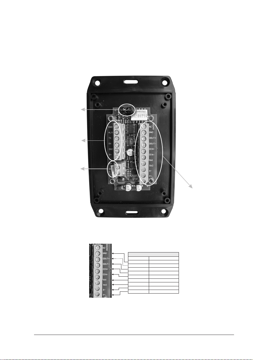
1.6 RADAR JUNCTION BOX CONNECTIONS
Referring to the diagram below, connect the color coded wires from the Radar
cable to the designated place on Terminal strip A in Radar Junction Box as follows.
MOUNTING
INSTRUCTIONS
1. Open the box unscrewing
the 4 bottom screws.
2. Connect the Radar cable
to the terminal A
JUMPER for RADAR
ON/OFF SWITCH
Terminal C
CHART PLOTTER
(see connection tables)
Terminal B
POWER SUPPLY
(see Radar specifications)
3. Connect the Power
supply to the terminal B
4. Connect the chart plotter
cable to the terminal C
5. Set up the jumper for
RADAR ON/OFF switch:
5a. Mount to permanently
power ON the Radar;
5b. Connect to a switch
to manually power
on/off the Radar.
5c. Remove to control
the power ON/OFF
via the chart plotter
with the external
alarm output signal.
Terminal A
RADAR
(see Radar cable label)
Terminal Strip A
Fig. 1.6a - Terminal Strip A Connection for MDS 1/MDS 8/MDS 9
User Manual
Fig. 1.6 - Junction Box
RADAR CABLE
WIRE COLOR FUNCTION
BLACK
ORANGE
YELLOW
BROWN
RED
GREEN
BLUE
BLACK (large wire)
WHITE (large wire)
DATAGND
DATAOUT+
DATAOUT-
DATAIN+
DATAIN-
POWER ON/OFF SWITCH 1
POWER ON/OFF SWITCH 2
RADAR SUPPLY-
RADAR SUPPLY+
11
Page 10
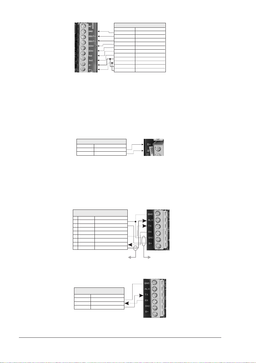
RADAR CABLE
WIRE COLOR FUNCTION
BLACK
ORANGE
YELLOW
BROWN
RED
GREEN
BLUE
BLACK (large wire)
WHITE (large wire)
BLUE (large wire)
RED (large wire)
DATAGND
DATAOUT+
DATAOUT-
DATAIN+
DATAIN-
POWER ON/OFF SWITCH 1
POWER ON/OFF SWITCH 2
RADAR SUPPLY-
RADAR SUPPLY+
MOTOR POWER-
MOTOR POWER+
Fig. 1.6a1 - Terminal Strip A Connection for MDS 10
Terminal Strip B IS TO BE CONNECTED TO POWER SUPPLY (12 TO 24 VDC NOMINAL)
Do not omit the in-line fuse unless a dedicated and fused terminal is available. If
so, install a 5 Amp fuse. If you are installing a MDS 10 open scanner Radar, it is
important to also connect the Red (+) to positive power terminal, and Blue (-) to
negative power terminal, as this provides power to scanner motor.
This terminal leads the power to the Scanner unit and to the chat plotter (*).
NOTE(*)Only if the chart plotter power wires are connected to Terminal strip C, on B+
and GND terminals.
12-24V POWER SUPPLY
WIRE COLOR FUNCTION
POWER SUPPLY+
RED
POWER SUPPLY-
BLACK
Fig. 1.6b - Terminal Strip B
B+
-
B
Please make sure that the connected power supply is able to supply the
current at the voltage required by the Radar to operate.
Terminal Strip C
See connection tables to determine proper way to connect the chart plotter to
Radar Junction Box.
WARNING
POWER & I/O CABLE
CONNECTION TO PORT 2
PIN WIRE COLOR FUNCTION
1
2
3
4
5
6
7
Connect to control the Radar ON/OFF via the chart plotter. Make sure that:
1) This signal is not used for any other operation (external alarm)
The jumper is removed on the junction box2)
8
BLACK
RED
WHITE
GREEN
GRAY
YELLOW
BROWN
BLUE
GND/COMMON
POWER INPUT+ (10-35 Vdc)
INPUT 1+
INPUT 1-
OUTPUT 2+
OUTPUT 1+
INPUT 2+
OUTPUT EXTERNALALARM
+
Connect to power the
chartplotter via the junction box
Fig. 1.6c - Connection to Port 2
QUICK DISCONNECT
BRACKET CABLE
WIRE COLOR FUNCTION
GND
BLACK
INPUT 2+
BROWN
OUTPUT 2+
GRAY
Fig. 1.6c1 - Connection to Port 2 for Quick Disconnect Bracket Cable
12 User Manual
Page 11

1.6.1 Jumper To Control Radar On/Off Operation
1.6.1.1 Radar Powered On all the time
Leave jumper located at top of Radar Junction Box mounted. This will keep powered On at all times.
1.6.1.2 Radar Powered On/Off Controlled by an External Switch
The two remaining small leads, the Green wire and the Blue wire, connect to the
On/Off control switch. The On/Off control switch does not switch the main power
leads to the scanner unit, but it does provide a signal that controls DC power
inside the scanner unit.
1.6.1.3 Radar Power On/Off Controlled by the Chart Plotter Software
NOT AVAILABLE FOR COLOR MAX WIDE I/E & COLOR MAX SEALINK I/E
Remove jumper. Connect the EXTERNAL ALARM signal of the chart plotter to
TERMINAL Strip C, Terminal ALR (see connection tables).
Setting up the chart plotter I/O in the following mode:
[MENU] + [MENU] + "ADVANCED" + [ENTER] + "Input/Output" + [ENTER]
+ "RADAR" + [ENTER] + "EXT. ALARM" + [ENTER]
Power the Radar On/Off directly from:
[MENU] + "POWER" + [ENTER] + "ON"/"OFF" + [ENTER]
1.6.2 Alternative Power Connection
You can feed the Power supply to the Radar directly.
1.6.2.1 Power Connections
♦ Route the large black and white wires directly to the power panel. No
switch is required.
♦ Connect the large black wire to the battery negative (—) terminal of
the power panel.
♦ Connect the large white wire (with the in-line fuse) to the battery posi-
tive (+) terminal of the power panel (12 to 24 VDC nominal). Do not
omit the in-line fuse unless a dedicated and fused terminal is available.
If so, install a 5 Amp fuse. If you are installing a MDS 10 open scanner
Radar, it is important to also connect the Red (+) to positive power
terminal, and Blue (-) to negative power terminal, as this provides
power to scanner motor.
This completes the installation of your Radar scanner unit.
Please proceed with setting up the data ports in your chart plotter, following the
instructions below.
1.7 SOFTWARE CONFIGURATION
First you have to install the Radar. Refer to the following paragraphs to configure
the chart plotter to operate with the Radar.
1.7.1 I/O Setup
Setting up the chart plotter I/O depends upon which port is used to connect the
Radar. If you use the connecting cable supplied with the Radar, the Port2 is the
default setting. In this case follow the procedure:
User Manual
[MENU] + [MENU] + "ADVANCED" + [ENTER] + "Input/Output" + [ENTER]
+ "Port 2 Input" + [ENTER] + "RADAR" + [ENTER]
13
Page 12

1.7.2 Warming Up
It has to be noted that at start-up the Radar needs a variable time from 90 to 120
seconds to heat up the magnetron (microwave emitting tube). During this time it
is not possible to turn on the transmission.
Radar pages are visible but with a small overlapping message window showing
the time remaining to Warm Up completion:
"Radar Warming Up! xx seconds remaining!"
At completion of the Warm Up sequence the following message will be displayed:
"Radar Warming Up! Warm Up Completed!"
This window shall remain open for 2 seconds, then it will close automatically.
At this point the Radar is ready for operation. Transmission is turned Off and
"STAND BY" message is displayed at the center of the Radar page.
1.7.3 Transmission On
Turn On the transmission pressing:
NOTE or following the procedure:
The Radar image is displayed on the screen.
[ENTER]
[MENU] + "TRANSMISSION" + [ENTER] + "ON" + [ENTER]
or using soft keys:
any soft key + [TX]
1.7.4 Radar calibration
At first installation it is necessary to properly calibrate the Radar:
The Radar calibration includes:
[MENU] + "TUNING" + [ENTER]
♦ Heading Line
♦ Antenna Parking Position (ONLY FOR MDS 9/MDS 10)
♦ Sector Transmission Off (ONLY FOR MDS 9/MDS 10)
♦ Transmission Trigger Delay
1.7.4.1 Heading Line
This function is used if the Radar Antenna was not installed pointing directly
parallel with the centerline of the vessel. Adjusting the heading line ensures that
targets are shown relative to your ship’s bow.
♦ select Head Up mode
[MENU] + "ORIENTATION" + [ENTER] + "HEAD UP" + [ENTER]
♦ Press [CLEAR] until the Radar page is shown.
♦ Select a target about 1- 2NM and adjust the vessels speed to accurately
head to the target (preferably on a flat calm day).
♦ If the target is not shown directly ahead on the Radar full page display,
adjust heading the line to correct the target heading:
[MENU] + "TUNING" + [ENTER] + "HEADING LINE" +
[ENTER] + Apply the Heading Correction + [ENTER]
♦ The screen updates as the heading line is adjusted. Repeat the steps until
the target is shown correctly.
1.7.4.2 Antenna Parking Position
AVAILABLE ONLY FOR MDS 9/MDS 10
When the Radar is turned Off, the antenna comes to a stop. If you want to have
the antenna to stop in a specific position, the Antenna Parking Position function
can be used to choose the desired antenna position. This function only controls
the antenna position at which the power to the motor is cut off. The distance
14 User Manual
Page 13
through which it comes to a stop from this point depends on temperature and
wind conditions. The setting of antenna does not affect the operation of the Radar
at all. To set the antenna position follow this procedure:
[MENU] + "TUNING" + [ENTER] + "ANTENNA PARKING POSITION" +
[ENTER]
Use the cursor keys to adjust the position (between 0 and 90).
The displayed number represents the change from the default setting. The final
setting that parks the antenna straight ahead will likely be a few degrees left or
right from the default setting.
1.7.4.3 Sector Transmission Off
AVAILABLE ONLY FOR MDS 9/MDS 10
This is used to block transmission and target reflection in some special application for fixed installation like sea watching. Within this sector, targets can not be
detected.
Selecting the Sector Transmission Off from the menu:
[MENU] + "TUNING" + [ENTER] + "SELECT TRANSMISSION OFF" + [ENTER]
Radar antenna
Sector OFF
Fig. 1.7.4.3 - Sector Off
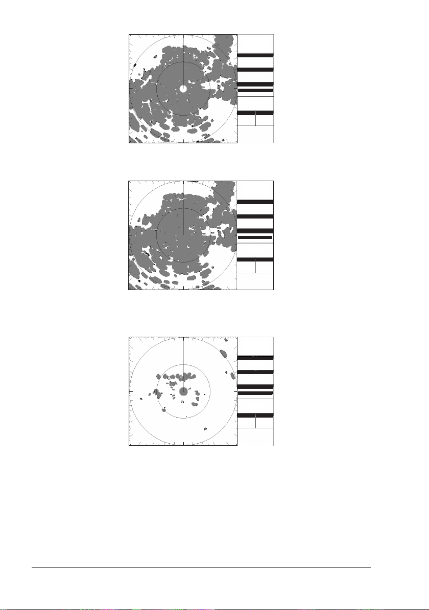
1.7.4.4 Transmission Trigger Delay
Tuning the Transmission Trigger Delay (TTD) allows making accurate distance
measurement. In practice, you need to align the start of the sweep with the
leading edge of the transmission pulse.
IMPORTANT: The unit comes with a default Tuning value already setup by the
factory but to obtain maximum precision you should finely adjust this value. Use
the following procedure.
♦ Enter the Transmission Trigger Delay page.
[MENU] + "TUNING" + [ENTER] + "TRANSMISSION TRIGGER DELAY" +
[ENTER]
Since the STC is automatically turned off when entering this page, the screen
appear completely covered with clutter, this is a mandatory condition to
allow properly setting the TTD. The screen should appear as follows:
User Manual
15
Page 14
Transmission
Trigger Delay
Tuning
Gain
055
MBS
050
Trans. Trigger Delay
095
Done
Rings
RNG
1/8 Nm1/4 Nm
Fig. 1.7.4.4 - Transmission Trigger Delay tuning (I)
♦ Set MBS to 0. The white spot in the Radar origin will disappear.
Transmission
Trigger Delay
Tuning
Gain
055
MBS
050
Trans. Trigger Delay
095
Done
Rings
RNG
1/8 Nm1/4 Nm
Fig. 1.7.4.4a- Transmission Trigger Delay tuning (II)
♦ Slowly decrease the GAIN value until the clutter clears out and you can
clearly distinguish a round spot in the Radar origin:
Transmission
Trigger Delay
Tuning
Gain
031
MBS
000
Trans. Trigger Delay
095
Done
Rings
RNG
1/8 Nm1/4 Nm
Fig. 1.7.4.4b - Transmission Trigger Delay tuning (III)
♦ If the Transmission Trigger Delay is properly tuned the spot in the Radar
origin should appear as in the picture above. In any case to be sure your
TTD is properly tuned try to decrease the Transmission Trigger Delay until a
hole start forming in the center of the round spot:
16 User Manual
Page 15
Transmission
Trigger Delay
Tuning
Gain
031
MBS
000
Trans. Trigger Delay
079
Done
Rings
RNG
1/8 Nm1/4 Nm
Fig. 1.7.4.4c - Transmission Trigger Delay tuning (IV)
♦ Now increase the TTD until the hole closes (not more than just the value to
make it close). The increase rate should be very slow: just increase by a
single step at the time and wait until you see the effect on the screen. When
the hole in the center of the spot closes you have reached the optimal TTD
setting.
Transmission
Trigger Delay
Tuning
Gain
031
MBS
000
Trans. Trigger Delay
095
Done
Rings
RNG
1/8 Nm1/4 Nm
Fig. 1.7.4.4d - Transmission Trigger Delay tuning (V)
♦ The spot in the Radar origin is the transmission pulse itself. Targets within
such range are not detectable because their echoes are completely overwritten
by the Radar still transmitting. Such spot is called Main Bang. To remove it
from the screen it is necessary to properly set the MBS (Main Bang Suppression) control. To do this, increase slowly the MBS. The spot is progressively
deleted from the inside toward the outside
Transmission
Trigger Delay
Tuning
Gain
031
MBS
039
Trans. Trigger Delay
095
Done
Rings
RNG
1/8 Nm1/4 Nm
Fig. 1.7.4.4e - Transmission Trigger Delay tuning (VI)
User Manual
17
Page 16
♦ Continue increasing the MBS until the spot completely disappear:
Transmission
Trigger Delay
Tuning
Gain
031
MBS
067
Trans. Trigger Delay
095
Done
Rings
RNG
1/8 Nm1/4 Nm
Fig. 1.7.4.4f - Transmission Trigger Delay tuning (VII)
♦ Select DONE to exit the TTD tuning menu saving your settings.
♦ The main Radar page is displayed. Please note that since initially Gain was
decreased, now it’s necessary to increase it back in order to achieve maximum sensitivity:
Rings
RNG
4Nm
1Nm
O
HDG 000 T
Heading
Motion
Relative Head Up
STC/FTC
Gain
55
59/Off
Int. Rej.
Exp
Off Of f
G.Z
Trails
Off Of f
SOG 1.0 Kts
O
COG 000 T
DST 9.468
nm
O
BRG 000 T
SENSITIVITY
GAIN
STC 059
FTC Off
INTERF.REJECTION
Fig. 1.7.4.4g - Transmission Trigger Delay tuning (VIII)
055
Off
Once the calibration has been performed, the calibration data is retained. However if a Clear RAM operation is performed it may be necessary to repeat the
calibration.
1.7.4.5 Automatic and Manual Tune
NOT NECESSARY AT FIRST INSTALLATION
The Tune control is used to tune the receiver in the Radar antenna for maximum
target returns on the display. The Radar comes from the factory already tuned so
this operation is not necessary at first installation. In general Radar Tuning may
be necessary if any component of the Radar is replaced for maintenance.
The Radar receiver can be tuned in Automatic or Manual mode. In Automatic Tune
mode, the Radar tunes itself automatically on all range scales. It is recom-
mended to execute the Tune function in Automatic mode. This generally
ensures that the Radar receiver is always tuned to receive the maximum signal.
If you choose the Manual Tune, you will need to adjust it again after 10 minutes,
after you have turned on the Radar, since the required setting will change after
the magnetron has warmed.
NOTE The Manual Tune function should be made only by professional operators.
18 User Manual
Page 17
Manual Tune
1/4 1/8
Done
Coarse Tuning
082
Manual Tuning
STC
059
128
Rings
RNG
1/8 Nm1/4 Nm
Fine Tuning
128
Gain
1/4 1/8
Done
Coarse Tuning
055
Manual Tuning
STC
059
130
Rings
RNG
1/8 Nm1/4 Nm
Fine Tuning
128
Gain
x
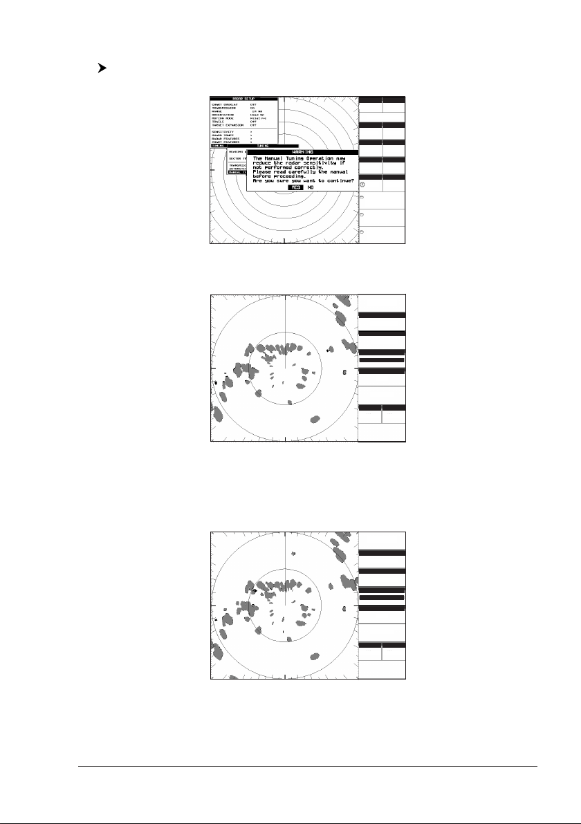
To execute manual tuning follow the procedure:
[MENU] + "TUNING" + [ENTER] + "MANUAL TUNE" + [ENTER]
♦ The following Warning message is displayed:
Rings
RNG
24 Nm
4Nm
O
HDG 007 T
Heading
Motion
Relative Head Up
STC/FTC
Gain
82
67/Off
Int. Rej.
Exp
Off Of f
G.Z
Trails
Off Of f
SOG 1.0 Kts
O
COG 007 T
DST 0.518
nm
O
BRG 072 T
O
43 33.715N
O
010 17.199E
Fig. 1.7.4.5 - Manual Tune Warning message
♦ Press [ENTER] to proceed, the Manual Tuning page is displayed:
Fig. 1.7.4.5a - Manual Tune page
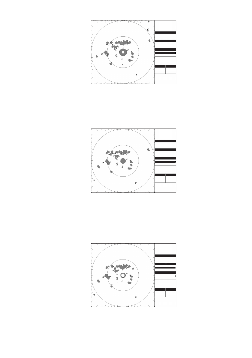
♦ Try increasing or decreasing the Course Tuning very slowly and in small
steps from its middle value (128) until you obtain the maximum echo returns. If no land or ship targets are available, you may tune for maximum
STC.
♦ Once the Course Tuning has been set, repeat the same procedure with the
Fine Tuning:
User Manual
Fig. 1.7.4.5b - Manual Tuning procedure (I)
19
Page 18

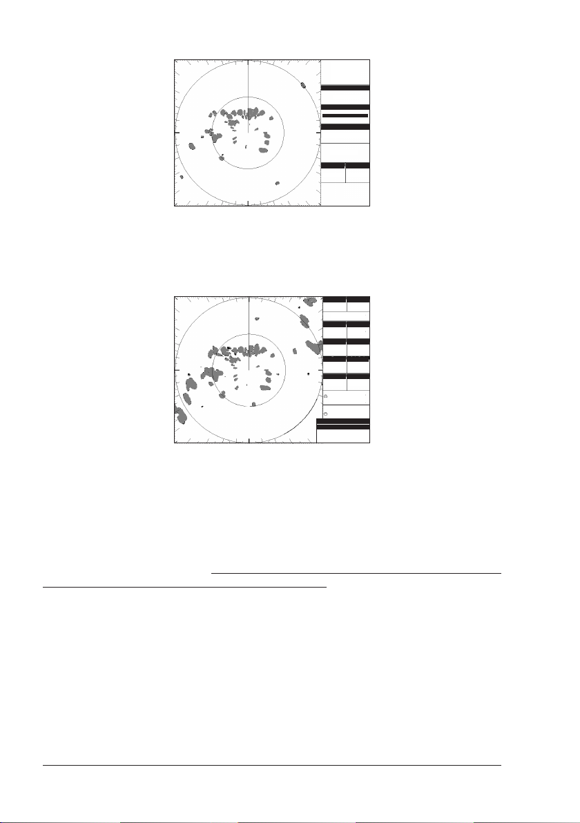
Manual Tuning
Gain
055
STC
059
Coarse Tuning
130
Fine Tuning
131
Done
Rings
RNG
1/8 Nm1/4 Nm
x
1/4 1/8
Fig. 1.7.4.5c - Manual Tuning procedure (II)
♦ Select DONE to exit the Manual Tuning page saving your settings.
Automatic Tune
To execute automatic tuning follow the procedure:
[MENU] + "TUNING" + [ENTER] + "AUTOMATIC TUNE" + [ENTER]
♦ The following Warning message is displayed to alert the user that the Auto
Tuning procedure may require up to 10 minutes. Please note that during
Auto Tuning all the Radar functionalities are disabled.
Rings
RNG
24 Nm
4Nm
O
HDG 000 T
Heading
Motion
Relative Head Up
STC/FTC
Gain
82
67/Off
Int. Rej.
Exp
Off Of f
G.Z
Trails
Off Of f
SOG 1.0 Kts
O
COG 000 T
DST 4.385
nm
O
BRG 096 T
O
42 49.451N
O
010 14.734E
Fig. 1.7.4.5d - Automatic Tune Warning message
♦ Press [ENTER] to proceed, the Automatic Tuning starts and the following
Window is displayed on the screen:
Rings
RNG
1
6
6Nm
1Nm
O
7
HDG 007 T
Heading
Motion
Relative Head Up
Gain
STC/FTC
100
0
0/Off
100
Int. Rej.
Exp
Off Of f
G.Z
Trails
Off Of f
SOG 1.0 Kts
O
COG 000 T
DST 4.385
nm
O
BRG 096 T
O
42 49.451N
O
010 14.734E
Fig. 1.7.4.5e - Automatic Tune page
♦ When the Auto Tuning completes the Warning Message is hidden and all
Radar functionalities return to be available.
20 User Manual
Page 19

1.7.4.6 Save Tuning to User C-CARD
This is useful to avoid the user having to retune up Radar after a Clear RAM
operation or a software update. The following data will be saved:
♦ Heading Line angle
♦ Antenna Parking Position
♦ Sector Transmission Off Start Angle
♦ Sector Transmission Off End Angle
♦ Transmission Trigger Delay
♦ Course Tune
♦ Fine Tune
Insert the User C-CARD into the slot, then follow the procedure:
[MENU] + "TUNING" + [ENTER] + "SAVE TUNING TO USER C-CARD" +
[ENTER]
The file name is given automatically as TUNING1.
1.7.4.7 Load Tuning from User C-CARD
Loads the complete settings from the User C-CARD and changes the active menu
settings.
Insert the User C-CARD into the slot, then follow the procedure:
[MENU] + "TUNING" + [ENTER] + "LOAD TUNING FROM USER C-CARD" +
[ENTER]
User Manual
21
Page 20

22 User Manual
Page 21

2. Functions
2.1 BASIC
2.1.1 Cross Cursor
When on the Full Radar page or when the focus is on the Radar window, moving
the Cursor Keys will show the cursor on the screen. It is automatically hidden
when the Cursor is not used for more than 5 seconds. It can temporarily be
hidden to check for small targets under it by pressing [CLEAR].
When the Cursor Keys are moved a popup window will show the position of the
Cursor, the Distance and Bearing from the cursor to the vessels position.
It is context-sensitive. The following table reports the list of objects and the labels
that appear under the cursor:
♦ Center of Radar CTR
♦ EBL/VRM E/V
♦ Parallel Cursor ///
♦ Guard Zone GZ
♦ Ship Heading Marker HM
Cross Cursor
Fig. 2.1.1 - The Cross Cursor in the default Radar picture
2.1.2 Chart Overlay
Chart Overlay function merges Radar and chart data into a single picture by
drawing Radar targets over the cartography. When in Chart Overlay mode, the
chart inherits the Radar page setting, e.g. Orientation, True Motion mode (for
more information refer to Chapter 6, 6.16).
To enable (On) or disable (Off ) the Chart Overlay follow this procedure:
NOTE Requires a heading and a position sensor connected to the chart plotter
User Manual
AVAILABLE ONLY IN THE RADAR FULL PAGE
[MENU] + "CHART OVERLAY" + [ENTER]
through an NMEA 0183 interface. The heading sensor can be either a
gyrocompass or a fluxgate compass. The gyrocompass provides the best
performance in all conditions.
23
Page 22

Fig. 2.1.2 - Chart Overlay
2.1.3 Range
Selects the Radar range among 1/8, 1/4, 1/2, 3/4, 1, 1 + 1/2, 2, 3, 4, 6, 8, 12,
16, 24, 36 and 48 Nm (the maximum range depends on the antenna used).
To select the Radar Range value follow this procedure:
[MENU] + "RANGE" + [ENTER]
NOTE Changing scale takes about 5 seconds.
Also it is possible to select the Range in Radar page using [ZOOM IN]/[ZOOM
OUT].
2.1.4 Orientation
The Radar orientation option allows to choose the display mode, Head Up (HU),
North Up (NU) or Track Up (TU), that refers to the top of the screen as it relates
to the direction of the boat.
The Radar direction modes are described in the following table:
Head Up : The Radar picture is displayed with the vessel’s current heading upwards. As the heading
North Up : The Radar picture is stabilized and displayed with north upwards. As heading changes, the ship’s
Track Up : The Radar picture is stabilized and displayed with the currently selected Course Leg upwards. As
NOTE Head Up cannot be selected in True Motion mode.
changes the picture will rotate. It doesn’t require heading information. It is the default value.
Heading Marker moves. Requires a heading sensor connected to the chart plotter.
heading changes, the ship’s heading marker moves. If you select a new course leg, the picture
rotates to display the new course leg upwards. Requires a heading sensor connected to the chart
plotter.
To change the orientation mode follow this procedure:
[MENU] + "ORIENTATION" + [ENTER]
2.1.5 Motion Mode
Allows choosing between two different presentation of targets and ship position over the
Radar screen Relative Motion (RM) and True Motion (TM). See the following table:
True : In True Motion, fixed Radar targets maintain a constant position on the screen, while your own ship
Relative : In Relative Motion your own ship’s position remains fixed on the Radar screen and all Radar
NOTE True Motion is only available in North Up and Track Up modes (not in Head Up
mode). Also True Motion requires a heading sensor and GPS position
information.
moves across the Radar image at the appropriate speed and heading. A map-like image is thus
displayed, with all moving vessels traveling in true perspective to each other and to fixed
landmasses. As your ship’s position approaches the edge of the screen, the Radar center offset
is automatically reset to reveal the area ahead of your ship.
targets move relative to your own ship. It is the default for the Radar display.
24 User Manual
Page 23

To change the Motion mode follow this procedure:
[MENU] + "MOTION MODE" + [ENTER]
2.1.6 Echo Trails Settings
Echo Trails causes the persistence of the Radar targets on the screen for the time
specified. Selecting an appropriate trail plotting time help determining the speed
and course of a target vessel and help prevent collision with it. Selects Radar
Trails among Continuous, 15 seconds, 30 seconds, 1 Minute, 3 Minutes, 6 Minutes
(or disables - Off). To choose the Echo Trails follow this procedure:
[MENU] + "ECHO TRAILS" + [ENTER]
2.1.7 Target Expansion
Target Expansion is used to enlarge the target size without changing the range.
This function is useful to see and detect very small targets in open seas. To enable
(On) or disable (Off) the Target Expansion follow this procedure:
[MENU] + "TARGET EXPANSION" + [ENTER]
2.2 SENSITIVITY
To select the Sensitivity menu follow this procedure:
NOTE The Sensitivity menu can be also opened by pressing:
2.2.1 Interference Rejection
Reduces the interference caused by Radar signals from other Radar units. It is
possible to turn Interference Rejection to Off, Level 1 (weak), Level 2 (middle),
Level 3 (strong). The higher you set the Interference Rejection value the less
interference you will receive.
To select the Interference Rejection value follow this procedure:
[MENU] + "SENSITIVITY" + [ENTER]
[ENTER]
directly from the Radar page when the Cross Cursor is not placed over any
features.
[MENU] + "SENSITIVITY" + [ENTER] + "INTERF REJECTION" + [ENTER]
2.2.2 Gain Adjustment
Controls the Radar Gain. To see more details on the screen, increase the receiver
sensitivity by selecting a higher gain percentage. If there is too much detail or if
the screen is cluttered, lowering the sensitivity may increase the clarity of the
display.
To select the Gain value follow this procedure:
[MENU] + "SENSITIVITY" + [ENTER] + "GAIN" + [ENTER]
NOTE The Gain can be also controlled by pressing:
[GAIN]
directly from the Radar page, after pressing any soft keys.
2.2.3 STC (Sensitivity Time Constant) Adjustment
Reduces the effects of the sea clutter that can adversely affect displayed targets.
To select the STC value follow this procedure:
NOTE The STC can be also controlled by pressing:
NOTE At low scales (as 1/4 of mile) some attempts are necessary to adjust STC value.
User Manual
[MENU] + "SENSITIVITY" + [ENTER] + "STC" + [ENTER]
[STC]
directly from the Radar page, after pressing any soft keys.
25
Page 24

2.2.4 FTC (Fast Time Constant) Adjustment
Reduces the effects of rain, snow, fog and cloud that can adversely affect displayed targets.
To select the FTC value follow this procedure:
NOTE The FTC can be also controlled by pressing:
NOTE At low scales (as 1/4 of mile) some attempts are necessary to adjust FTC value.
[MENU] + "SENSITIVITY" + [ENTER] + "FTC" + [ENTER]
[FTC]
directly from the Radar page, after pressing any soft keys.
2.2.5 MBS (Main Bang Suppression) Adjustment
The MBS adjustment is fundamental for getting clear near center spot image. In
general, you must adjust MBS and STC and Gain to obtain desired Radar image.
To select the MBS value follow this procedure:
AVAILABLE ONLY FOR MDS 9/MDS 10
[MENU] + "SENSITIVITY" + [ENTER] + "MBS" + [ENTER]
2.3 RADAR FEATURES
2.3.1 Cursor Window
The content of the Cursor Window depends on cursor location.
It shows detailed information on the cursor Lat/Lon, the cursor bearing and range,
the center of the screen, EBL/VRM, Guard Zone, Heading Marker and Parallel
Cursor. It is hidden when the cursor is hidden.
To turn On or Off the Cursor Window follow this procedure:
[MENU] + "RADAR FEATURES" + [ENTER] + "CURSOR WINDOW" + [ENTER]
Cursor Window
Fig. 2.3.1- The Cursor Window
2.3.2 Heading Marker
The Heading Marker (HM) is the line from the own vessel’s position to the edge of
the picture at the vessel’s current heading with respect to the North indicated by
the compass.
26 User Manual
Page 25

Heading Marker (HM)
Fig. 2.3.2- The Heading Marker
The Heading Marker is updated each time the Radar image is updated. It can
temporarily be hidden to check for small targets under it by positioning the Cross
Cursor over it and pressing [CLEAR].
To turn On or Off the display of the Heading Marker follow this procedure:
[MENU] + "RADAR FEATURES" + [ENTER] + "HEADING MARKER" + [ENTER]
2.3.3 Degree Scale
The Degree Scale is the graduated scale located on the most external visible
range ring edge of the Radar page, with major ticks at 0, 10, 20, …, 350 degrees
and minor ticks at 5, 15, 25, …, 355 degrees.
Degree Scale
Fig. 2.3.3- The Degree Scale
To hide (Off ) or unhide (On) the display of the Degree Scale follow this procedure:
[MENU] + "RADAR FEATURES" + [ENTER] + "DEGREE SCALE" + [ENTER]
2.3.4 Range Rings
The Range Rings are concentric rings centered on the ship position, equally spaced.
User Manual
27
Page 26

Range Rings
Fig. 2.3.4- The Range Rings
They are used to give an immediate idea of the range of targets from the ship.
Their number and spacing are adjusted automatically accordingly with the Range
Scale. The indication of the Range Rings interval is indicated in the Status Bar
(see Par. 3.2.1).
To turn On or Off the display of the Range Rings follow the procedure:
[MENU] + "RADAR FEATURES" + [ENTER] + "RANGE RINGS" + [ENTER]
2.3.5 Compass Rose
The Compass Rose is an icon used to identify four main directions: North, South,
East and West. It is North oriented.
Compass Rose
Fig. 2.3.5- The Compass Rose in the default Radar picture
NOTE Requires a heading and position sensor connected to the chart plotter
To hide (Off ) or unhide (On) the display of the Compass Rose follow the procedure:
[MENU] + "RADAR FEATURES" + [ENTER] + "COMPASS ROSE" + [ENTER]
2.3.6 EBL & VRM
Electronic Bearing Lines (EBL) and Variable Range Marker (VRM) are used to
measure the range (distance) and the bearing between two points. A standard
28 User Manual
Page 27

VRM is displayed by default as a circle with its center located on your vessel’s
position, and EBL is displayed as a line from the vessel's position to the edge of
the Radar picture display.
EBL/VRM
Fig. 2.3.6 - EBL & VRM display
2.3.6.1 Handling of EBL/VRM
Positioning the Cross Cursor on the EBL/VRM activates a pop up message "E/V"
underneath the cursor. It is possible to allow to Move, Hook and Hide it.
♦ [MOVE]: Allows moving EBL/VRM from the own ship's position to any
location of the Radar page. Pressing [CONFIRM] once more confirms the
new position; pressing [CANCEL] resets the original position.
♦ [HOOK]: hooks the EBL/VRM cross point allowing changing bearing and
range using the Cursor Keys. Pressing [CONFIRM] once more confirms
the new range and bearing, pressing [CANCEL] resets the original range
and bearing values.
♦ [OFF]: disables the EBL/VRM.
Up to 2 EBL/VRM's may be placed on the Radar screen at the same time. To turn
EBL/VRM On or Off or to select 1 EBL/VRM, 2 EBL/VRM or both (1+2) EBL/VRM,
follow this procedure:
[MENU] + "RADAR FEATURES" + [ENTER] + "EBL/VRM" + [ENTER]
2.3.7 Parallel Cursor
A set of parallel lines with first line passing through the ship’s position and next
lines being placed equally spaced and extending from the ship’s position towards
one direction.
User Manual
29
Page 28

Parallel Cursor
Fig. 2.3.7 - Parallel Cursor display
The user can change the angle of the lines and the range between lines. It is used
to measure the bearing of other boats, navigate at a fixed distance from the
coast, measure the distance between two points.
The display of the Parallel Cursor can be turned On or Off following this procedure:
[MENU] + "RADAR FEATURES" + [ENTER] + "PARALLEL CURSOR" + [ENTER]
2.3.8 Center Offset
Allows to move the Radar center in any location of the screen.
2.3.8.1 Handling of Center Offset
If the Radar is in Relative Motion mode, positioning the Cross Cursor on the
center of the Radar image, allows editing the Center Offset ("CTR" message is
shown under the cursor position).
The soft keys are automatically displayed:
♦ [MOVE]: hooks the Radar image center allowing the user, using the
Cursor Keys, to move it at any location on the Radar screen. At this
point pressing [ENTER] confirms the new position of the center, pressing [CLEAR] resets the position of the Radar image at 0,0.
♦ [OFFSET]: opens an edit window where it is possible to edit the X Offset
and Y Offset position in pixel at which the center of the screen is positioned.
♦ [CTR SCRN]: resets screen offset position to 0,0.
NOTE In True Motion mode the user cannot change the screen center position.
To set the Center Offset follow this procedure:
[MENU] + "RADAR FEATURES" + [ENTER] + "CENTER OFFSET" + [ENTER]
2.3.9 Status Bar
Allows to display the Status Bar on the screen. Note that in Radar Split pages the
Status Bar is displayed always in compact mode to allow for more space for the
graphical data.
To enable (On) or disable (Off ) the Status Bar displaying follow the procedure:
30 User Manual
AVAILABLE ONLY IN THE RADAR SPLIT PAGES
[MENU] + "RADAR FEATURES" + [ENTER] + "STATUS BAR" + [ENTER]
Page 29

2.4 CHART FEATURES
2.4.1 Chart Overlay Mode
Selects which cartographic objects are to be displayed when Chart Overlay function is active in Radar Full page.
The following chart presets are available:
AVAILABLE ONLY IN THE RADAR FULL PAGE.
♦ Full: Full cartographic representation.
♦ Medium: includes “Low” settings plus Ports & Services and Auto Chart Boundaries.
♦ Low: includes also area fills, important city names, Nav-Aids & Lights and
Underwater Object icons.
♦ Minimum: only the coast lines and elevation objects, no area fill.
♦ As Cartography: inherits settings from the current cartography setting.
♦ Custom: Custom chart representation.
To select the desired Chart Overlay Mode follow this procedure:
[MENU] + "CHART FEATURES" + [ENTER] + "CHART OVERLAY MODE" +
[ENTER]
2.4.2 Chart Synchronization
When Chart Synchronization is enabled, the chart display is synchronized to the
Radar display. This function is enabled when Home mode is active (e.g. by pressing [CLEAR] from the chart screen). An alert window showing the message "Radar - Chart Synchronization mode On" is displayed.
To enable (On) or disable (Off ) the Chart Synchronization follow this procedure:
AVAILABLE ONLY IN THE RADAR CHART SPLIT PAGE
[MENU] + "CHART FEATURES" + [ENTER] + "CHART SYNCHRONIZATION" +
[ENTER]
2.4.3 Cursor Echo
This function allows to correlate targets on the Radar display with objects in the
chart.
Moving the Radar cursor on Radar display will cause moving another cursor over
the chart. The cursor over the chart shall be positioned over the same Lat/Lon of
the cursor over the Radar.
When the Cursor Echo function is enabled, the Radar cursor in the chart display is
always shown even if the cursor in the Radar display is hidden.
To enable (On) or disable (Off ) the Cursor Echo follow this procedure:
CHART FEATURES" + [ENTER] + "CART. OBJECTS DISPLAY" + [ENTER]
AVAILABLE ONLY IN THE RADAR CHART SPLIT PAGE
[MENU] + "CHART FEATURES" + [ENTER] + "CURSOR ECHO" + [ENTER]
2.5 GUARD ZONES
Your Radar allows a function to help you avoid a collision. It is possible to set an
alarm to trigger when a target is within a specified zone, the Guard Zone.
It is allowed to display up to 2 Guard Zones, Sector or Circular.
User Manual
31
Page 30

Guard Zone
Fig. 2.5 - Guard Zone display
When a Guard Zone is active, the Guard Alarm sounds when a target enters its
area.
NOTE A Guard Zone only operates when the whole zone is displayed on the screen.
In addition, a Guard Zone is inactive for 10 seconds after it is placed or resized, to avoid inappropriate alarms during positioning.
2.5.1 Handling of Guard Zone
Positioning the Cross Cursor over a Guard Zone, causes the message "GZ" to be
displayed under the cursor. It is possible to handle the Guard Zone.
♦ [HOOK]: allows changing Guard Zone range by moving up/down Cursor
Keys. Pressing [CONFIRM] to confirm, [CANCEL] otherwise.
♦ [TYPE]: allows changing Guard Zone type: press [SECTOR] to select the
Sector Guard Zone, press [CIRCULAR] to select the Circular Guard Zone.
♦ [OFF]: disables the Guard Zone.
2.5.2 Guard Zone Sensitivity
It defines a limit (selectable from 0 to 100) under which echoes activate an alarm
condition, when detected inside a Guard Zone.
Guard Zone Sensitivity default is 50.
The value 100 is the most sensitive (the system is always on, every detected echo
cause an alarm condition) and the value 000 is the least sensitive (same as switching
the alarm off).
To turn the alarm On or Off follow this procedure:
[MENU] + "GUARD ZONES" + [ENTER] + "GUARD ZONE" + [ENTER]
32 User Manual
Page 31

3. Radar Pages
This section will assist you to select the preferred Radar page.
NOTE The Radar display page is available only if the Radar is connected and powered
3.1 PAGES SELECTION
The Page Selection menu allows you to change the Radar page displayed. To
access this menu:
COLOR MAX 11/COLOR MAX PRO/COLOR MAX 15:
TRAWL PLOT 12:
The menu now shows five selections related to the Radar: Radar Full page ("RADAR"), Radar Split Chart page ("RADAR/CHART"), Radar Split Fish Finder page
("RADAR/FF"), Radar Split Highway page ("RADAR/NAV DATA"), Radar Combo
Page ("RADAR/FF/CHART/NAV DATA"). Move the cursor to select the desired
item and then press [ENTER].
On, and the Radar is in Transmit mode (see Chapter 1).
[MENU] + [MENU] + "PAGE" + [ENTER] + "RADAR" + [ENTER] + select the
desired page + [ENTER]
[DATA] + "RADAR" + [ENTER] + select the desired page + [ENTER]
[PAGE] + "RADAR" + [ENTER] + select the desired page + [ENTER]
The Radar Full page
Radar Split Chart page
Radar Split Fish Finder page
Radar Split Data page Radar Combo page
Fig. 3.1 - Available Radar pages
3.1.1 Selection by Soft Key
The default soft keys configuration can be customized. When the Radar is connected, any soft key can be assigned any of the Radar pages.
From the Chart page, pressing and holding down any of the four soft key shows a
pop-up window on the top of the soft key pressed that contains all possible data
pages assignable to the soft key pressed. Move the Cursor key up/down to place
User Manual
33
Page 32

the selector on the desired item; move the Cursor key to the right or press [ENTER]
to set the selected item; move the Cursor key to the left or press [CLEAR] to
close the pop-up window.
In the picture below, the four soft keys are customized to select four among the
five available Radar pages:
Fig. 3.1.1 - Radar page selection by Soft Key
Press [RD STD] to show the Full page, [RD+MAP] to show the Radar Split Chart
page, [RD+FF] to show the Radar Split Fish Finder page, [RD+DTA] to show the
Radar Split Data page and [COMBO 4] to show the Radar/Chart/Fish Finder/
Highway page.
3.2 STATUS BAR
You may choose to select the data displayed in the boxes in the system set up.
1
RNG (Radar Range) and Range rings interval
Current Heading
2
Motion Mode and Heading Mode indication
3
Gain and STC/FTC indication
4
Expansion and Interference Rejection
5
Guard Zone alarms and Trails
6
Ship Speed Over Ground and Course Over
7
Ground
Ship Distance and Bearing from destination
8
Ship Lat/Lon
9
Cursor Window
10
Fig.3.2 - The Default Status Bar
1
3
5
7
10
2
4
6
8
9
Note that in Radar Split pages the Status Bar displayed always in compact mode
to allow more space for the graphical data (see Par. 2.3.9):
34 User Manual
Page 33

RANGE and Range rings interval
1
Guard Zone alarms
2
Current Heading
3
Heading Mode indication
4
Motion Mode indication
5
Distance to Destination
6
Bearing to Destination
7
Ship Speed Over Ground
8
Course Over Ground
9
2
1
Fig.3.2a - The "compact" Status Bar
3
4
5
7
6
8 9
3.3 MENU HANDLING ON FULL PAGES
When in Radar Full page pressing [MENU] once opens the Radar Setup menu.
Pressing [MENU] twice opens the Main menu.
3.4 SELECTION OF THE "ACTIVE" VIEW IN SPLIT/
COMBO PAGES
Yellow frame
Fig. 3.4- Selection of active View
When in Split/Combo pages, the active view is highlighted by a focus (Yellow
frame). The keyboard commands are related to that focused view. To move the
focus press [MENU] twice.
User Manual
35
Page 34

36 User Manual
Page 35

4. Technical Specifications
This chapter provides specifications of the several types of Radar.
4.1 MDS 1
Antenna unit
♦ Power supply : 10.8 to 31.2 VDC
♦ Power consumption : 30W or less
♦ Preheat times : 90 sec
♦ Aerial : Radome 0.9 Feet
♦ Peak power output : 2kW
♦ Transmitting frequency : 9445+/-30MHz
♦ Beam width (degree) Horizontal : 7°
♦ Vertical : 25°
♦ Side Lobes Within +/-10° : <=-20dB
♦ Rotation : 30rpm
♦ Pulse Length (μsec)/PRF (Hz) S : 0.1/2200
♦ M, M1 : 0.3/1100
♦ L, M2 : 0.8/550
♦ IF center frequency : 60MHz (Linear amplifier)
♦ IF bandwidth S : 6MHz
♦ M, M1 : 6MHz
♦ L, M2 : 3MHz
♦ Noise figure : 10dB nominal
♦ Operating Temperature : -25°C ~ +55° C
♦ Operation in wind (relative) : 100 knots
♦ Water Resistance : IPX6 (IEC60529)
♦ Preheat times output (by 5 sec step) : 85 sec to 5 sec
Dimensions and Mounting
Fig. 4.1 - Radar MDS 1 (I)
User Manual
37
Page 36

Weight: 4.5 kg (10 lb) without cable
Weight: 5.5 kg (12.5 lb) 10m cable included
Fig. 4.1a - Radar MDS 1 (II)
4.2 MDS 8
Antenna unit
♦ Power supply : 10.8 to 41.6 VDC
♦ Power consumption : 30W or less
♦ Preheat times : 90 sec
♦ Aerial : Radome 1.5 Feet
♦ Peak power output : 2kW
♦ Transmitting frequency : 9445+/-30MHz
♦ Beam width (degree) Horizontal : 4.7°
♦ Vertical : 25°
♦ Side Lobes Within +/-10° : <=-20dB
♦ Rotation : 30rpm
♦ Pulse Length (μsec)/PRF (Hz) S : 0.1/2200
♦ M, M1 : 0.3/1100
♦ L, M2 : 0.8/550
♦ IF center frequency : 60MHz (Linear amplifier)
♦ IF bandwidth S : 6MHz
♦ M, M1 : 6MHz
♦ L, M2 : 3MHz
♦ Noise figure : 10dB nominal
♦ Operating Temperature : -25°C ~ +55°C
♦ Operation in wind (relative) : 100 knots
♦ Water Resistance : IPX6 (IEC60529)
♦ Preheat times output (by 5 sec step) : 85 sec to 5 sec
38 User Manual
Page 37

Dimensions and Mounting
Fig. 4.2 - Radar MDS 8 (I)
Weight: 8.1 kg (18.0 lb)
: 6.8 kg (15.0 lb) without
Weight cable
10m cable included
Fig. 4.2a - Radar MDS 8 (II)
4.3 MDS 9
Antenna unit
♦ Power supply : 10.8 to 41.6 VDC
♦ Power consumption : 45W or less
♦ Preheat times : 120 sec
♦ Aerial : Radome 1.8 Feet
♦ Peak power output : 4kW
♦ Trasmitting frequency : 9410+/-30MHz
♦ Beam width (degree) Horizontal : 4.0°
♦ Vertical : 25°
♦ Side Lobes Within +/-10° : <=-20dB
♦ Rotation : 24rpm
♦ Pulse Length (μsec)/PRF (Hz) S : 0.1/2000
♦ M, M1 : 0.25/2000
User Manual
39
Page 38

♦ L, M2 : 0.5/1000
♦ L, L1 : 1.0/500
♦ IF center frequency : 60MHz (Linear amplifier)
♦ IF bandwidth S : 6MHz
♦ M, M1 : 6MHz
♦ L, M2 : 3MHz
♦ L, L1 : 3MHz
♦ Noise figure : 6.0dB or less
♦ Operating Temperature : -25°C ~ +55°C
♦ Operation in wind (relative) : 100 knots
♦ Water Resistance : IPX6 (IEC60529)
♦ Preheat times output (by 5 sec step) : 115 sec to 5 sec
Dimensions and Mounting
Fig. 4.3 - Radar MDS 9 (I)
Weight: 9.7 kg (21.5lb) 10m cable included
Weight: 8.4 kg (19.0lb) without cable
Fig. 4.3a - Radar MDS 9 (II)
40 User Manual
Page 39

4.4 MDS 10
Antenna unit
♦ Power supply : 10.8 to 41.6 VDC
♦ Power consumption : 80W or less
♦ Preheat times : 120 sec
♦ Aerial : Open 4 or 5 Feet
♦ Peak power output : 4kW
♦ Trasmitting frequency : 9410+/-30MHz
♦ Beam width (degree) Horizontal : 2.4° or 1.7°
♦ Vertical : 25°
♦ Side Lobes Within +/-10° : <=-23dB
♦ Outside +/-10°: <=-32dB
♦ Rotation : 24rpm
♦ Pulse Length (μsec)/PRF (Hz) S : 0.06/4000
♦ M, M1 : 0.15/2000
♦ L, M2 : 0.4/1000
♦ L, L1 : 1.0/500
♦ IF center frequency : 60MHz (Linear amplifier)
♦ IF bandwidth S : 20MHz
♦ M, M1 : 20MHz
♦ L, M2 : 5MHz
♦ L, L1 : 5MHz
♦ Noise figure : 5.0dB or less
♦ Operating Temperature : -25°C ~ +55°C
♦ Operation in wind (relative) : 70 knots
♦ Water Resistance : IPX6 (IEC60529)
♦ Preheat times output (by 5 sec step) : 115 sec to 5 sec
Dimensions and Mounting
3.5 feet 1067 (47 1/4)
4.5 feet 1372 (59 1/16)
User Manual
Fig. 4.4 - Radar SWR 10 (I)
41
Page 40

Fig. 4.4a - Radar MDS 10 (II)
Weight: 21.2 Kg (47lb) 4 feet
Weight: 21.9 Kg (49lb) 5 feet
42 User Manual
Page 41

5. Troubleshooting
5.1 The Radar page is not available
This means you didn’t configure the I/O setup to connect to the Radar. Enter the
I/O Setup menu (see procedure at Par. 1.7.1) and select the Radar on the serial
port to which the Radar is connected.
5.2 The message "Please Turn On Radar" is displayed on the
Radar window
This means that even if the I/O Setup has been configured for Radar, no Radar is
being detected. This may depend on several factors:
♦ Verify that the correct serial port is set in the I/O Setup menu, eventually
try setting the Radar on another serial port.
♦ Check that the Radar is connected to the chart plotter, to the same serial
port as set in the I/O Setup menu, in case try connecting it to another
serial port.
♦ Verify that all the connections in the Junction Box are done properly.
♦ Verify using a Voltage Meter that the Radar power supply level at the Junc-
tion Box is at least 12V. The Radar is able to operate with 10V but some
volts may be dropped due to the cable length.
If everything above is correct, try shorting the green and the blue wires in cable
coming from the Radar. If the Radar still doesn’t work you need to call for assistance.
5.3 The Radar preheating countdown timer is displayed but
when the preheating terminates it restarts over and over
again
The power supply level is too low. This may be caused by battery low, cable too
long, cable section to narrow.
5.4 Too much clutter near the Radar screen center
This is a typical phenomenon with Radar. Echoes from nearby vessel may hit
other objects like other vessels or other objects randomly and reflections can be
received by Radar antenna due to very short distance between the objects. This is
normal condition in a port where nearby targets (such as sailboat masts) may
cause multiple reflections. In this case, increase the STC and decreasing the
GAIN.
5.5 During navigation in open sea the center of the screen is
covered by a large spot
It means that most probably the Transmission Trigger Delay and/or the Main Bang
Suppression need to be correctly tuned (refer to Par. 1.7.4.4).
5.6 After turning transmission On, the Radar page remains
completely black
The Gain setting could be too low or STC setting too high. The Radar is probably
not properly tuned. Execute the Automatic Tuning procedure to restore optimal
performance (refer to Par. 1.7.4.5).
User Manual
43
Page 42

5.7 The Radar sensitivity appears to be low
Radar sensitivity depends on several factors. To increase sensitivity act as follows:
♦ Execute the Automatic Tuning procedure to ensure that the Radar is per-
fectly tuned.
♦ Increase the GAIN.
♦ Reduce the STC, since the STC has the effect to reduce the echo intensity
of nearby targets.
♦ Turn Off the FTC, since it has the effect to reduce the echoes intensity of
big targets.
5.8 Radar targets are delayed with respect to the antenna
rotation
The Radar image on the GPS is updated every 2.5 seconds as information is
acquired from the antenna. This could cause a mis-match between the actual
target position and the targets shown on the screen.
5.9 Radar target appear to be pulsing
This is a rather common problem for any Radar. For long distance targets, when
the Radar pulse hits a target, the reflection strength which depends on the hit
angle. Perpendicular hits give the strongest echo. Hard objects give stronger echo
and soft objects give weaker echo.
To eliminate the pulsing effect of Radar targets the Echo Trails function may be
used (see Par. 2.1.6).
5.10 Stationary target appear to be oscillating around their
actual position
Radar targets may appear to be oscillating around their actual position due to the
movement of your vessel. In fact even a minimum oscillation of the position
where the Radar is located may cause an apparent movement of the targets
detected.
For short distance targets, surface waves lower the detectivity. The STC should be
adjusted to properly to maximize the detectivity.
44 User Manual
Page 43

6. Frequently Asked Questions
6.1 What should I do at first Radar installation?
At first installation its necessary to:
1) properly set up the Radar calibration
2) set up the I/O to detect the Radar
6.2 How can I turn Radar power On/Off
Radar power On/Off can be either directly controlled from the chart plotter (NOT
AVAILABLE FOR COLOR MAX WIDE I/E & COLOR MAX SEALINK I/E) or by an external switch
depending on how you have set up your chart plotter.
In case the power is managed by the chart plotter you can turn power On by
pressing [MENU] when in the Radar Page. Otherwise you have to turn power On
by acting on the external switch.
NOTE For a pratical matter we suggest to use Radar Powered On/Off controlled by
6.3 How should I setup the chart plotter to control the Radar
Please refer to Chapter 1 for wiring schematic.
6.4 How can I turn Radar Transmission On/Off?
Press [ENTER] in the Radar page or enter the Radar Main Menu and set Transmission On from the related menu choice. Transmission can be set in Stand-by
only from the Radar menu.
an external switch, because at a glance we can check the Radar status without
having to switch to the Radar page.
power On/Off?
6.5 What is the preheating?
Each time you power On the Radar you must allow 90 to 120 seconds (depending
on the Radar model) to warm up the Radar. Operating the Radar before this time
could cause damage to it. For this reason the chart plotter doesn't allow operating
the Radar until the preheating is complete.
6.6 Some time the preheating takes less than 90 seconds, is
this normal?
Yes it is. It means that the Radar was already powered on at the time you turned
On the chart plotter so the preheating started before.
6.7 What is the Radar calibration?
Radar calibration is a set of options that allows to properly set the Radar to work
on your boat. You can set up the Heading correction, to compensate of orientation
errors due to the installation, the Radar trigger delay to properly adjust the Radar
beam as to correctly measure ranges, and finally the sensitivity of the Radar to
maximize the Radar sensitivity.
6.8 When and how should I adjust the Radar heading?
At first installation you should correct the Radar heading as to ensure that it is
perfectly aligned with your bow.
User Manual
45
Page 44

6.9 When and how should I adjust the Radar Trigger delay?
At first installation. It is required to ensure the Radar is capable to perfectly
measure ranges and avoid distortions. Please follow the procedure described at
Par. 1.7.4.4.
6.10 When should I do the Radar tuning?
Radar tuning is generally not necessary since it is already tuned at the factory.
However in the long run or in case some components are replaced it could be
necessary to perform tuning to achieve the maximum sensitivity.
6.11 Should I use the Manual or Auto Tuning?
We strongly suggest to use the Auto Tuning that generally is capable to give
optimal results.
6.12 How should I do the Manual Tuning?
Follow procedure at Par. 1.7.4.5.
6.13 What is the STC, and how should I operate it?
STC is the Sensitivity Time Constant. It is used to reduce the sensitivity and thus
the clutter in the range closer to the Radar. Operate the STC as to reduce the
echoes coming from the closer ranges to an acceptable level.
6.14 What is the FTC and how should I operate it?
FTC is the Fast Time Constant. It is used to reduce the echoes coming from large
objects that can hide other small objects. It is also called the rain control since it
is capable to reduce the effects of the rain on the display.
6.15 What is the MBS?
The MBS is the Main Bang Suppression. It is used to suppress the stronger echoes
caused by Radar transmission in the receiver. It is like the STC but its operates in
a shorter range.
6.16 I can't turn Chart Overlay On, why?
To turn Chart Overlay On you must have both a GPS and a heading sensor connected to the chart plotter. If the chart plotter doesn't detect such devices it will
automatically disable the Chart Overlay option.
6.17 I can't set the North Up or Course Up navigation mode,
why?
To turn On the North Up or Course Up navigation modes you must have both a
GPS and a heading sensor connected to the chart plotter. If the chart plotter
doesn't detect such devices it will automatically disable such option.
6.18 I can't set up the True Motion mode, why?
To turn On the True Motion mode you must have both a GPS and a heading sensor
connected to the chart plotter. If the chart plotter doesn't detect such devices it
will automatically disable such option.
6.19 Why do I need a Heading Sensor and a GPS to use all
Radar functionalities?
Because the Radar need to know the current position of the boat and its current
heading.
46 User Manual
Page 45

6.20 What are the functions that require a GPS or a Heading
Sensor?
Function Heading GPS FIX
North Up Radar orientation Y N
Track Up Radar orientation Y N
True Motion mode Y Y
Chart Overlay Y Y
Radar/Chart Synchronization Y Y
Cursor Echo Y Y
Head Up Mode N N
Relative Motion mode N N
6.21 Is it better a gyrocompass or a flux gate compass?
The gyrocompass it is a better choice because it is faster but it is much more
expensive. The flux gate compass is slower but it is much cheaper. Using a fluxgate you have to expect to see delays in the rotation of the chart when in Chart
Overlay mode.
6.22 How can I be advised of potential dangers for the
navigation?
Using the Guard Zone alarms.
6.23 What are Guard Zones?
Guard Zones are zones defined by the user that causes an audible and visual
alarm to be triggered when a target exceeding a certain density enters into it. The
density of the target that may trigger the alarm is regulated by mean of the
Guard Zone sensitivity. There are of two types of Guard Zones: Circular or Sectorial. They are fixed with respect to the ship position and heading but their range
and orientation (only for sector type) are user defined.
6.24 How should I set the Guard Zone sensitivity?
Guard Zone sensitivity must be regulated accordingly to the current Gain of the
Radar. The higher the sensitivity the smaller the target that may trigger the alarm.
In general if you regulated your Radar to obtain a clean picture you can set the
Guard Zone sensitivity very high to detect even the smaller targets. In case the
Radar picture has clutter present due to the higher gain set, you'll have to reduce
the Guard Zone sensitivity to avoid triggering false alarms. In general a way to
set the maximum sensitivity for a Guard Zone is to start increasing the sensitivity
until an alarm is triggered and then reduce the sensitivity until the alarm stops.
User Manual
47
Page 46

48 User Manual
Page 47

A. What is Radar?
A.1 GENERAL
The word “radar” is an acronym for “RAdio Detecting And Ranging.” In very simple terms, this is how it works. A radio transmitter sends a quick microwave
pulse, and then a receiver listens for that signal’s echo when it is bounced back
from something in its path. The returning signal is processed by a computer to
determine its relative distance, position and bearing. This information is graphically displayed on a screen for you to see. Other boats or ships, navigational
markers, landmasses and such are referred to as targets.
By knowing how long it takes for a signal to return, the distance to a target can be
determined. As the Radar antenna scans through a 360-degree rotation, it can
show where the target is relative to your position. By repeated scans, you can see
which direction another vessel is moving.
Other ship
Radar
Fig. A.1 - Radar
A.1.1 Antenna
How Radar will perform is largely determined by its antenna or scanner. Increasing the size of the antenna improves long-range performance and target discrimination, or the ability to distinguish two separate targets at a distance. The critical
factors are the antenna’s beam width and side lobe level. Typically, a Radar antenna will radiate a tightly focused beam from the front of the array. The longer
the antenna array is, the narrower the beam width will be.
Additionally, it will also emit smaller amounts of energy to each side. The lower
the side lobe level, the less the effect of a false echo.
Buoy
Radar
Antenna
A.1.2 Side Lobe
The beam in which the strongest radio signal is radiated from the antenna is
called the “main lobe”. Those beams that are radiated in other directions are
referred to as the “side lobes”. The side lobe level refers to the difference in level
(signal strength) between the largest side lobe and the main lobe.
User Manual
49
Page 48

Main
Side
lobe
Fig. A.1.2 - Antenna Pattern
Beam
Antenna
A.2 CHARACTERISTICS OF RADAR WAVE
Radio waves travel out from the antenna while bending slightly along the earth’s
surface. The amount they bend depends on atmospheric conditions. The sight
distance of a Radar generally is about 6% longer than the optical sight distance
and is calculated using this equation:
Radar sight distance (NM) = 2.22 ( antenna height (m) + target height (m))
Line of sight
h1
Earth
Fig. A.2 - Radar wave
Radar Radio Wave
h2
A.2.1 Targets difficult to display on screen
The intensity of the reflected radio signal from a target depends on the distance,
height, and size of the target, as well as its material and shape, along with the
Radar’s transmitter power output and antenna size. Targets made of fibreglass,
wood, or other low-reflectance materials or those that have a small incident angle
are difficult to display on a screen. Sandy beaches, and sandy or muddy shallows
can be difficult to catch. Because there’s not much to reflect a signal back to you,
a coastline can actually be closer to your boat than it appears on the screen.
Invisible
Apparent coastline
Visible
Fig. A.2.1 - Targets difficult to display on screen
Actual (invisible)
coastline
3
1
HU
A.2.2 Shadow zones of Radar
Radar waves propagate in a straight line. A high outcropping of land or a large
ship will create a shadow zone behind it and prevent you from seeing targets on
the other side. More importantly, if a mast or some part of the boat’s superstructure is in the path of the antenna’s sweep, this will also create a shadow zone. No
targets will be recognized behind it and it could create a dangerous situation.
50 User Manual
Page 49

A.2.3 False echoes
Sometimes Radar will display targets on screen that do not exist in the real world.
You should be aware of howand why this happens.
A.2.3.1 Ghost echoes
Sometimes one large object very near your boat will appear as two different targets
on screen. One is the actual Radar echo. The other is a ghost echo generated by a rereflection of the original signal. It comes back to your own boat, bounces back to the
target, and then is picked up by the antenna on the second bounce. The actual echo
appears at the correct distance and bearing on the screen. The ghost echo appears
somewhere behind your boat. This type of false echo is also generated by re-reflection of waves from bridges, break walls or building along shore.
Target
Direct
reflection path
Secondary
reflection path
Mast etc.
Direction of ghost echo
Fig. A.2.3.1 - Ghost Echoes
3
1
HU
Real echo
Ghost echo
A.2.3.2 Multiple echoes
If there is a large vertical reflecting surface near your boat, as in the case when
you pass alongside a large ship, Radar signals are repeatedly bounced back and
forth between your boat and the other object. Two to four images appear on the
screen at equal intervals in the same bearing. This is called a multiple echo. The
image appearing closest to you is the real echo. Multiple echoes will disappear as
you move away from the reflecting object or its bearing changes.
3
1
HU
Real echo
{
Multiple
echoes
Fig. A.2.3.2 - Multiple Echoes
A.2.3.3 False echoes caused by side lobe
An antenna’s side lobe emissions are low power, and will not register distant
targets. However, if there is a strong reflecting target near your boat, it sometimes may appear as a circular-arc false echo on the screen.
When near large targets or land, your boat's mast may sometimes appear as
circular-arc shaped false echo.
User Manual
WARNING
51
Page 50

Main beam
Side lobes
False sidelobe
echoes
Real echo
Antenna
Fig. A.2.3.3 - False Echoes caused by side lobe
3
1
HU
A.2.3.4 Distant False echoes caused by duct phenomenon
The duct phenomenon sometimes occurs when meteorological conditions create a
temperature inversion between layers of air. When this happens, Radar waves
propagate erratically and can reach a location considerably farther away from
your boat than the Radar’s maximum distance range. What appears on screen is
a false echo that looks to be nearer than the actual target. Since the true echo
from the distant target is outside the measurement capabilities of the Radar, its
apparent distance will change when you change ranges, and you can conclude
that it’s a false echo.
A.2.3.5 Radar interference
If another boat’s Radar is operating on the same frequency as yours, it can create
interference on your display. The interference usually appears as spiral or radial
patterns. This Radar has an interference rejection control to eliminate interference. Turn it on to reduce or eliminate the interference.
3
1
HU
Radar interference
Fig. A.2.3.5 - Radar interference
52 User Manual
Page 51

B. Installation
Ls
R
D
Scanner Unit
Obstacle
Keel
θ
B.1 MORE INSTALLATION CONSIDERATIONS
B.1.1 Shifting from keel line
By shifting the scanner position from the keel line to the starboard side of the
boat, it is possible to move shadow zones to the port side. This makes it possible
to keep a clear view to the bow. The distance to be shifted can calculated using
the following equation:
where Ls = distance to be shifted from keel line
B.1.2 Obtaining sufficient dip angle
Raise the scanner position so that there is a sufficient dip angle available between
the line of sight from the scanner to the obstacle and the horizontal line. By
raising the dip angle above 5°, it is possible to prevent mid- and long-distance
shadow zones. The Radar cannot detect objects below the line of sight.
Ls = 0.4R+D/2 [m] (when R<15m)
Ls = 0.025R+D/2 [m] (when R>=15m)
D = diameter of obstacle on keel line
R = distance from scanner to obstacle
Fig. B.1.1 - Shifting from keel line
Horizontal line
Line of sight
Fig. B.1.2 - Obtaining sufficient dip angle
B.2 INSTALLING SCANNER UNIT
Use a mounting base such as the ones shown in Fig. B.1.1, or you can install the
scanner directly to a roof or other flat surface. Be certain you keep the water
drain tube clear. It’s located at the bottom of the scanner unit.
NOTE If the mounting bracket or surface has a curvature of more than 2mm, use
User Manual
spacers with the mounting bolts to prevent stress on the scanner housing.
53
Page 52

Do not use an edge that might trap water.
Fig. B.2 - Installing scanner unit
54 User Manual
Page 53

Analytical Index
A
Antenna ................................................... 49
Antenna unit ........................... 37, 38, 39, 41
Automatic Tuning ..................... 20, 43, 44, 46
C
calibration .......................................... 14, 45
Center Offset ............................................ 30
Chart Overlay ..................................... 23, 46
Chart Overlay Mode ................................... 31
Chart Plotter Software ............................... 13
Chart Synchronization ............................... 31
Clear RAM ................................................ 18
clutter ..................................................... 43
compass .................................................. 47
Compass Rose .......................................... 28
Conventions ............................................... 8
Course Tuning .......................................... 19
Course Up ................................................ 46
Cross Cursor ............................................. 23
CTR ......................................................... 30
Cursor ..................................................... 23
Cursor Echo .............................................. 31
Cursor Window ......................................... 26
D
dangers ................................................... 47
Degree Scale ............................................ 27
Dimensions .............................................. 37
duct phenomenon ..................................... 52
E
EBL ......................................................... 28
Echo Trails Settings ................................... 25
External Switch .................................. 13, 45
F
False echoes ............................................ 51
Fast Time Constant ................................... 46
Fine Tuning .............................................. 19
First Installation ................................. 18, 45
flux gate compass ..................................... 47
focus ....................................................... 35
FTC ..............................................26, 44, 46
Functions ................................................. 23
G
GAIN ...................................... 16, 25, 43, 44
Ghost echoes ............................................ 51
Guard Zone ........................................ 31, 47
Guard Zone Sensitivity .............................. 47
gyrocompass ............................................ 47
H
Head Up .................................................. 24
heading ................................................... 45
Heading Marker ........................................ 26
Heading Sensor ........................................ 46
HM .......................................................... 26
HU .......................................................... 24
I
I/O Setup ........................................... 13, 43
Installation .................................... 9, 45, 53
Interference Rejection ............................... 25
J
Junction Box ...................................... 11, 43
M
Main Bang Suppression ...................26, 43, 46
Manual Tuning .................................... 19, 46
MBS ............................................. 16, 26, 46
MDS 1 ..................................................... 37
MDS 10 ................................................... 41
MDS 8 ..................................................... 38
MDS 9 ..................................................... 39
Motion Mode ....................................... 24, 46
Mounting .......................... 10, 37, 39, 40, 41
Multiple echoes ......................................... 51
N
North Up ............................................ 24, 46
NU .......................................................... 24
O
Orientation ............................................... 24
P
Packing List ................................................ 8
Parallel Cursor .......................................... 29
port ........................................................ 13
Power Connections .................................... 13
Power consumption .................. 37, 38, 39, 41
power On/Off ....................................... 13, 45
Power supply ........................... 37, 38, 39, 41
Preheat ....................... 37, 38, 39, 41, 43, 45
R
Radar ...................................................... 49
Radar calibration ....................................... 45
Radar Full page ........................................ 35
Radar interference .................................... 52
Radar page ......................................... 33, 43
Radar Trigger delay ................................... 46
Radar tuning ............................................ 46
Range ..................................................... 24
Range Rings ............................................. 27
Relative Motion ......................................... 24
S
scanner ............................................. 49, 53
Sensitivity ....................................25, 32, 44
Sensitivity Time Constant .......................... 46
serial port ................................................ 43
Shadow zone ............................................ 50
Side Lobe ........................................... 49, 51
Soft Key .................................................. 33
Specifications ........................................... 37
Status Bar ................................................ 30
STC .................................. 19, 25, 43, 44, 46
T
Target ............................................... 44, 50
Target Expansion ...................................... 25
Track Up .................................................. 24
Transmission ............................................ 14
Transmission On ....................................... 43
Transmission On/Off .................................. 45
Transmission Trigger Delay ........................ 43
Troubleshooting ........................................ 43
True Motion ........................................ 24, 46
TTD ......................................................... 15
TU .......................................................... 24
Tune control ............................................. 18
Tuning ............................................... 15, 46
Turn On Radar .......................................... 43
V
VRM ........................................................ 28
W
Warming Up ............................................. 14
User Manual
55
Page 54

CERTIFICATE OF LIMITED WARRANTY
Providing you present a valid proof of purchase, SI-TEX warrants all parts of each new product against
defect in material and workmanship under normal use and will repair or exchange any parts proven to be
defective at no charge for a period of two years for parts and one year for labor from the date of purchase,
except as provided below under Limited Warranty Exceptions.
Defects will be corrected during normal working hours by an authorized SI- TEX dealer, service center, or at
the SI-TEX office in St. Petersburg, Florida. There will be no charge for labor for a period of one year from
the date of purchase, except as provided below under Limited Warranty Exceptions.
This Warranty and Proof of Purchase must be made available to the authorized SI-TEX service location or
dealer at the time of service.
SI-TEX will not be responsible for equipment which has been subjected to water or lightning damage,
accident, abuse, or misuse, nor any equipment on w hich the serial number label has been removed, altered
or mutilated. SI-TEX assumes no responsibility for damage incurred during installation.
This Limited Warranty is effective only with respect to the original purchaser. Any cost associated with
transduc er replacement, other than the cost of the transducer itself, is specifically excluded from this Limited
Warranty. Travel cost incurred will not be accepted for SI -TEX products. THERE ARE NO WARRANTIES
WHICH EXTEND BEYOND THE DESCRIPTION OF THE FACE HEREOF .
Charges for overtime, stand-by, holiday, and per diem are specifically excluded from the Limited Warranty.
Chart paper, stylus, stylus belt, lamps, and fuses are consumable items and are not covered by this Limited
Warranty. Installa tion workmanship or materials, except as provided directly by SI-TEX, are not covered by
this Limited Warranty. SI-TEX equipment or parts thereof which have been repaired or altered except by an
authorized SI-TEX dealer or service center are not warranted in any respect.
Transducer, software update, battery, microphone, magnetron, and microwave components and water
damage on water resistant VHF radio are items excluded from the two-year warranty and are covered by
warranty for a period of one year for both parts and labor. SI-TEX will not, at any time, assume any costs or
labor charges for checkout or external line fuse replacement or problems not found to be at fault in
equipment itself.
THERE ARE NO WARRANTIES OR GUARANTEES EXPRESSED OR IMPLIED WHICH EXT END
BEYOND THE DESCRIPTION ON THE FACE HEREOF, INCLUDING WARRANTIES OF FITNESS FOR A
PARTICULAR PURPOSE AND MERCHANTABILITY. SI -TEX HAS NO OTHER LIABILITY TO PURCHASE
FOR DIRECT OR CONSEQUENTIAL DAMAGE OR ANY THEORY INCLUDING ABSOLUTE LIABILITY,
TORT, OR C ONTRACT. THIS LIMITED WARRANTY CANNOT BE ALTERED OR MODIFIED IN ANY WAY
AND SHALL BE INTERPRETED IN ACCORDANCE WITH THE LAWS OF THE STATE OF FLORIDA. THIS
WARRANTY IS LIMITED TO THE CONTINENTAL U.S.A., ALASKA, HAWAII, AND CANADA.
To provide better flexibility, SI -TEX gives you the option of obtaining service under this warranty by either:
a) Contacting an authorized SI-TEX service station (The closest service station may be found by contacting your
dealer of purchase.) OR
b) Shipping your equipment prepaid via UPS or truck with insurance prepaid to SI -TEX at the address
provided below. SI-TEX will, whenever possible, make all repairs covered by Limited Warranty
within two weeks of receiving the equipment in Florida and return same to you, freight prepaid.
c) You must present a copy of your Purchase Sales Slip at the time you request warranty service.
SI-TEX offers a complete line of quality marine electronics including echo sounders, electronic charting systems,
radars, autopilots, GPS/WAAS/Loran receivers, SSB receivers, VHF radios, and integrated systems.
For more information, contact your SI -TEX dealer or the main office, located in St. Petersburg, Florida.
LIMITED WARRANTY EXCEPTIONS
SPECIFIC EXCLUSIONS
HOW TO OBTAIN SERVICE U NDER THIS WARRANTY
Shipping/Mailing Address
:
SI-TEX
Koden America, Inc.
11001 Roosevelt Blvd., Suite 800
St. Petersburg, FL 33716
727- 576-5734
56 User Manual
 Loading...