

Page 1
Smart DGPS WAAS Receiver
"GPU series"
USER MANUAL
Smart DGPS WAAS Receiver "GPU series"
UM code: MAGPUxx1AE, B290507
3
Page 2

Caution
The Smart DGPS WAAS "GPU series" units are believed to be accurate and reliable, but they can be
misinterpreted. For this reason we suggest that you read carefully this User Manual and make sure
you understand with its contents before using the Smart DGPS WAAS "GPU series" units. For a
safe navigation compare information received from GPS to all available navigation indications received from other electronic navigation navaids that you carry on board.
Do not open the Smart DGPS WAAS "GPU series" units. There are not serviceable parts inside.
Repairs should only be made by an authorized electronic technician, please contact your local dealer
(any unauthorized repair could result in damage to the unit and this damage may not be covered by
the warranty).
Limited Warranty
The manufacturer warrants each Smart DGPS WAAS "GPU series" units to be free from defects in
material and workmanship under normal use and service for a period of 24 months from original
retail purchase. During the warranty period, the manufacturer will repair or replace any component
which fails in normal use without charges for parts or labour.
To receive warranty service, contact your local authorized dealer for shipping instructions. The
Smart DGPS WAAS "GPU series" unit should be securely packed with its tracking code clearly
written on the outside of the package, shipping to be paid by the customer. Include a copy of the
original sales receipt as the proof of purchase. The manufacturer will return the Smart DGPS WAAS
"GPU series""GPU series" unit to the purchaser freight prepaid.
This limited warranty does not extent to any Smart DGPS WAAS "GPU series" unit which has
been subjected to misuse, neglect, accident, incorrect wiring or improper installation. The manufacturer reserves the right to repair or replace the Smart DGPS WAAS "GPU series" unit at its sole
discretion.
This warranty is in lieu of all other warranties either expressed or implied.
THIS IS THE ONLY WARRANTY. THE MANUFACTURER EXPRESSLY DISCLAIMS ANY
AND ALL OTHER WARRANTIES INCLUDING WARRANTIES OF SUITABILITY OR FITNESS FOR A PARTICULAR PURPOSE. IN NO EVENT WILL MANUFACTURER BE LIABLE
FOR CONSEQUENTIAL DAMAGES OR LOSS OF USE. THIS WARRANTY GIVES YOU SPECIFIC LEGAL RIGHTS WHICH MAY VARY FROM STATE TO STATE.
Note
We will not be liable for errors contained herein, or for incidental or consequential damages in connection with the performance or
use of this material.
4
Smart DGPS WAAS Receiver "GPU series"
Page 3

Table of Content
1 Smart DGPS WAAS Receiver ............................................................................................. 7
1.1 TECHNICAL SPECIFICATIONS ................................................................ 7
1.1.1 Physical Characteristics ................................................................... 7
1.1.2 Electrical Characteristics .................................................................. 7
1.1.3 Performance ..................................................................................... 8
1.1.4 Environmental Characteristics ......................................................... 8
1.2 WIRING ............................................................................................. 9
1.2.1 Diagram For GPU with connector .................................................... 9
1.2.2 Diagram For GPU ............................................................................. 9
1.3 SOFTWARE INTERFACE .......................................................................... 9
1.4 MECHANICAL CHARACTERISTICS & MOUNTING GPU WITH CONNECTOR MODEL 10
1.4.1 Installing .......................................................................................... 10
1.4.2 Dimensions ..................................................................................... 12
1.5 MECHANICAL CHARACTERISTICS & MOUNTING GPU MODEL ..................... 12
1.5.1 Installing .......................................................................................... 12
1.5.2 Dimensions ..................................................................................... 14
Smart DGPS WAAS Receiver "GPU series"
5
Page 4

6
Smart DGPS WAAS Receiver "GPU series"
Page 5

1
Smart DGPS WAAS Receiver
This Smart DGPS WAAS receiver is based on a ultimate 16 channels GPS
engine that delivers accuracy better than three meters by decoding the GPS correction signals from the satellite-based WAAS (Wide Area Augmentation System). The
GPS engine, interface electronics and the passive antenna are enclosed inside the
water-proof plastic housing. This provides advanced state of the art GPS performance in an easy to use package.
1.1 TECHNICAL SPECIFICATIONS
1.1.1 PHYSICAL CHARACTERISTICS
Color : Ivory white.
Dimensions : 97mm in diameter x 32mm in height (flush mounted) or
61,5mm on flag-pole mount.
Weight : 160 grams (without cable).
Cable GPU : white 15 meter 8x28AWG cable with 6 pins female connector
Cable GPU with connector : white 15 meter 8x28AWG cable with 6 pins female and
8 pins female connectors
1.1.2 ELECTRICAL CHARACTERISTICS
Input Voltage : 10 Vdc to 35 Vdc unregulated
Power Consumption : 0.8 W max
Electrical Interface : TTL voltage levels, RS-232 polarity
Smart DGPS WAAS Receiver "GPU series"
7
Page 6

1.1.3 PERFORMANCE
Receiving Method : 16 channels parallel (up to 3 for WAAS Satellites)
Receiving Frequency : 1575.42MHz (L1, C/A code)
Receiving Sensitivity : Less than -134 dBm
Time to First Fix (TTFF)
Warm start : 33 seconds (typical)
Cold start : 40 seconds (typical)
Accuracy
Position : Less than 2.5mCEP1 5.0mSEP2: GPS:(SA=OFF; HDOP<4)
Less than 2.0mCEP1 3.0mSEP2: DGPS:(SA=OFF; HDOP<4)
Dynamics
Acceleration : Strong Signals <= 4g
Weak Signals typical 1g
Altitude3: 18000m
Velocity3: 1850Km/h (515 m/sec)
DGPS format : WAAS; EGNOS; MSAS
Output format : NMEA-0183 Baud rate 4800 N81
NMEA Output messages : GGA, RMC, GSA, GSV, TXT
Geodetic Datum : WGS84
Note1
CEP = Circular Error Probability: The radius of a horizontal circle, centered at the
antenna's True position, containing 50% of the fixes.
Note2
SEP = Spherical Error Probability: The radius of the sphere, centered at the antenna's True
position, containing 50% of the fixes.
Note3
One of this limit can exceded but not both.
1.1.4 ENVIRONMENTAL CHARACTERISTICS
Operating Temperature: 0° C~ +60° C
Storage Temperature : -20° C~ +85° C
Relative Humidity : 95% non-condensing
Water Resistance : 100% waterproof
8
Smart DGPS WAAS Receiver "GPU series"
Page 7

1.2 WIRING
See the following tables for a functional description of each wire in the GPS
cable.
1.2.1 DIAGRAM FOR GPU WITH CONNECTOR
Fig. 1.2.1 - GPS Connection for GPU with connector
1.2.2 DIAGRAM FOR GPU
Fig. 1.2.2 - GPS Connection for GPU
WARNING !!!
Cross check the connection on the User Manual of the device connected to the GPS.
1.3 SOFTWARE INTERFACE
The GPS products interface protocol design is based on the National Marine
Electronics Association's NMEA 0183 ASCII interface specification. These standards are defined in "NMEA 0183 Version 2.0" (for more information see NMEA,
www..nmea.org).
Smart DGPS WAAS Receiver "GPU series"
9
Page 8

1.4 MECHANICAL CHARACTERISTICS & MOUNTING
GPU WITH CONNECTOR MODEL
1.4.1 INSTALLING
Choose a location for the antenna that has a clear view of the sky. Ensure
there are no major obstructions or fixtures in the immediate proximity to the antenna. The antenna relies on direct “line of sight” satellite reception. If you are unsure that the chosen location is suitable it may be advisable to mount the antenna in
a temporary manner to verify correct operation. The thread used on the antenna (1
inch, 14 TPI) is an industry standard thread used on a wide range of mounting brackets, including the swivel joints commonly used for angled surfaces. However due to
the manufacturing process of these mounting brackets you may see that there is
some slop when tightening down the antenna to the bracket. This is of no concern
however as the antenna must be tightened until the antenna stops rotating on the
antenna mounting bracket.
10
Fig.1.4.1 - Installing GPS Antenna (I)
The antenna design also allows for easy flush mounting.
1. Apply the adhesive mounting template sheet in the area that was verified
to receive satellite signal well.
2. Then, following template instruction, drill a 0,95 inch (24 mm) hole and
three 0,155 inch (4 mm) holes.
Smart DGPS WAAS Receiver "GPU series"
Page 9

Fig.1.4.1a - Installing GPS Antenna (II)
3. Remove the template and let the cable go through the central hole.
4. Apply a small coat of RTV to the underside of the antenna.
5. Place the antenna and then screw it with the three M3 screws.
Fig.1.4.1b - Installing GPS Antenna (III)
Smart DGPS WAAS Receiver "GPU series"
11
Page 10

1.4.2 DIMENSIONS
Fig.1.4.2 - GPS Antenna Dimensions
1.5 MECHANICAL CHARACTERISTICS & MOUNTING
GPU MODEL
1.5.1 INSTALLING
Choose a location for the antenna that has a clear view of the sky. Ensure
there are no major obstructions or fixtures in the immediate proximity to the antenna. The antenna relies on direct “line of sight” satellite reception. If you are unsure that the chosen location is suitable it may be advisable to mount the antenna in
a temporary manner to verify correct operation. The thread used on the antenna (1
inch, 14 TPI) is an industry standard thread used on a wide range of mounting brackets, including the swivel joints commonly used for angled surfaces. However due to
the manufacturing process of these mounting brackets you may see that there is
some slop when tightening down the antenna to the bracket. This is of no concern
however as the antenna must be tightened until the antenna stops rotating on the
antenna mounting bracket.
12
Smart DGPS WAAS Receiver "GPU series"
Page 11

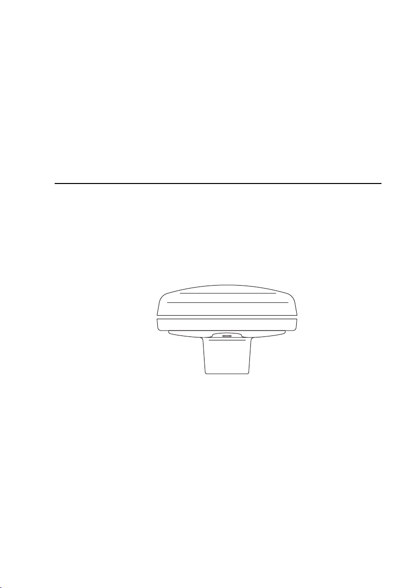
Fig.1.5.1 - Installing GPS Antenna (I)
The antenna design also allows for easy flush mounting.
1. Apply the adhesive mounting template sheet in the area that was verified
to receive satellite signal well.
2. Then, following template instruction, drill a 0,63 inch (16 mm) hole and
three 0,155 inch (4 mm) holes.
Fig.1.5.1a - Installing GPS Antenna (II)
3. Remove the template and let the cable go through the central hole.
4. Apply a small coat of RTV to the underside of the antenna.
5. Place the antenna and then screw it with the three M3 screws.
Smart DGPS WAAS Receiver "GPU series"
13
Page 12

Fig.1.5.1b - Installing GPS Antenna (III)
1.5.2 DIMENSIONS
Fig.1.5.2 - GPS Antenna Dimensions
14
Smart DGPS WAAS Receiver "GPU series"
 Loading...