

Sitecom WL-350 User Manual
Wireless Media Router
WL-350
Full Manual

WL-350 Wireless Media Router Full Manual
INTRODUCTION............................................................................................ 4
F
EATURES & BENEFITS
P
ACKAGE CONTENTS
S
AFETY GUIDELINES
P
RODUCT LAYOUT
B
ACK LABEL
S
YSTEM REQUIREMENTS
1 UNDERSTANDING THE HARDWARE...................................................... 11
H
ARDWARE INSTALLATION
IP A
DDRESS CONFIGURATION
2 INTERNET CONNECTION WIZARD........................................................ 13
3 WI-FI PROTECTED SETUP WIZARD.......................................................... 15
A
DD A WIRELESS DEVICE
U
SING THE
U
SING THE PUSH BUTTON
4 ADVANCED WEB CONFIGURATION .......................................................... 19
L
OGGING IN
4.1 H
Device.................................................................................................... 20
Wireless ................................................................................................. 20
Logs ...................................................................................................... 22
Stats...................................................................................................... 23
DHCP ..................................................................................................... 24
Firewall .................................................................................................. 25
4.2 BASIC ........................................................................................ 26
Network ................................................................................................. 26
Wireless ................................................................................................. 28
WAN ...................................................................................................... 33
Advanced Wireless................................................................................... 41
Advanced Network................................................................................... 42
4.3 F
Virtual Server.......................................................................................... 44
Special Application................................................................................... 45
Port Forwarding....................................................................................... 46
Access Control ........................................................................................ 47
Website Filter.......................................................................................... 49
Schedules............................................................................................... 50
4.4 A
Dynamic DNS.......................................................................................... 51
StreamEngine ......................................................................................... 52
Routing .................................................................................................. 53
MAC Address Filter................................................................................... 54
Firewall Settings ...................................................................................... 55
WISH ..................................................................................................... 59
Inbound Filter ......................................................................................... 61
Bandwidth .............................................................................................. 62
Users ........................................................... Error! Bookmark not defined.
4.5 T
..........................................................................................8
PIN ........................................................................................ 17
........................................................................................ 19
OME
........................................................................................ 20
IREWALL
DVANCED SETTINGS
OOLBOX
........................................................................................ 44
........................................................................................ 66
.......................................................................................5
..........................................................................................6
..........................................................................................6
..........................................................................................7
......................................................................................9
................................................................................. 11
............................................................................. 12
.................................................................................. 16
................................................................................. 17
................................................................................. 51
2

WL-350 Wireless Media Router Full Manual
Time Configuration .................................................................................. 66
System Settings ...................................................................................... 67
Firmware................................................................................................ 71
Syslog.................................................................................................... 71
Administrator Settings ............................................................................. 72
APPENDIX A FCC INTERFERENCE STATEMENT ............................................ 74
3

Introduction
The WL-350 is a draft 802.11n compliant device that delivers up to 6x faster
speeds than 802.11g while staying backward compatible with 802.11g and
802.11b devices.
It is not only a Wireless Access Point, which lets you connect to the network
without wires. There's also a built-in 4-port full-duplex 10/100/1000 Gigabit
Switch to connect your wired-Ethernet devices together. The Router function ties
it all together and lets your whole network share a high-speed cable or DSL
Internet connection.
The Access Point built into the Router uses advanced MIMO (Multi-Input, MultiOutput) technology to transmit multiple steams of data in a single wireless
channel. The robust signal travels farther, maintaining wireless connections up to
3 times farther than standard 802.11g, eliminating dead spots and extending
network range.
To protect the data and privacy, the Router can encode all wireless transmissions
with 64/128-bit encryption. It can serve as your network's DHCP Server, has a
powerful SPI firewall to protect your PCs against intruders and most known
Internet attacks, and supports VPN pass-through. The router also provides easy
configuration with the web browser-based configuration utility.
The incredible speed and the fully automatic QoS function of the 802.11n
(draft2.0) Gigabit Router is ideal for media-centric applications like streaming
video, gaming, and VoIP telephony. It is designed to run multiple media-intense
data streams through the network at the same time, with no degradation in
performance.

Features & Benefits
Features Benefits
High Speed Data Rate Up to
Capable of handling heavy data
300Mbps
Concurrent Dualband
(2.4GHz and 5GHz)
IEEE 802.11n draft Compliant
and backward compatible with
802.11b/g
Four built-in 10/100/1000Mbps
Gigabit Switch Ports (AutoCrossover)
Supports DNS/ DDNS
Supports NAT (Network Address
Translation)/NAPT
Hide SSID
Firewall supports Virtual Server
Mapping, DMZ, IP Filter, ICMP
Blocking, SPI
Support 802.1x authenticator,
802.11i (WPA/WPA2, AES), VPN
pass-thru mechanisms
WDS (Wireless Distribution
payloads such as MPEG video
streaming
Connect your client devices via the
2.4GHz band, while streaming media
on the clean 5GHz band.
Fully interoperable with IEEE
802.11b/g/n devices
Scalability, able to extend your
network
Lets users assign a fixed host and
domain name to a dynamic Internet IP
address.
Shares single Internet account and
provides a type of firewall by hiding
internal IP addresses for keeping
hacker out
Avoids unallowable users sharing
bandwidth, increases efficiency of the
network
Avoids the attacks of Hackers or
Viruses from Internet
Provide mutual authentication (Client
and dynamic encryption keys to
enhance security
Make wireless AP and Bridge mode
System)
Universal Plug and Play (UPnP™) Works with most Internet gaming and
Filter Scheduling The filter can be scheduled by days,
Real time alert The detection of a list for Hacker log-
Web configuration Helps administrators to remotely
simultaneously as a wireless repeater
instant messaging applications for
automatic Internet access
hours or minutes for easy management
in information
configure or manage the Router via
Telnet/Web-browser

Package Contents
Open the package carefully, and make sure that none of the items listed below
are missing. Do not discard the packing materials; in case of return, the device
must be shipped in its original package.
- One WL-350 Wireless Media Router
- One 12V/1.25A Power Adapter
- UTP Cable
- One CD-ROM with User’s Manual
- One Quick Installation Guide
- Warranty Card
Safety Guidelines
In order to reduce the risk of fire, electric shock and injury, please adhere to the
following safety guidelines.
- Carefully follow the instructions in this manual; also follow all instruction
labels on the device.
- Except for the power adapter supplied, the device should not be
connected to any other adapters.
- Do not spill liquid of any kind on the device.
- Do not place the device on an unstable stand or table. The device may
drop and become damaged.
- Do not expose the device to direct sunlight.
- Do not place any hot devices close to this device, as they may degrade
or cause damage to the device.
- Do not place any heavy objects on top of the device.
- Do not use liquid cleaners or aerosol cleaners. Use a soft dry cloth for
cleaning.
Product Layout
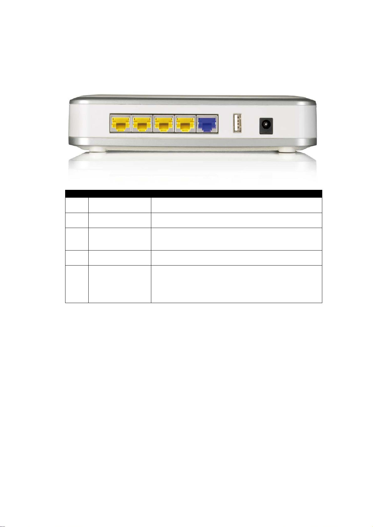
Item Label Description
1 LAN Ports
(yellow)
2 WAN Port (blue) Use an Ethernet cable to connect this port to your
3 DC Connector Use the power cable and connect the adapter to the
4 USB port The USB port can be used to connect a USB memory
5 WPS (on the top
of the router)
Use an Ethernet cable to connect each port to a
computer on your Local Area Network (LAN).
WAN router/modem.
power socket on the wall, and the DC inlet into the
DC connector.
stick or hard disk.
WPS (Wireless Push Button) is used for Wi-Fi
Protected Setup. By pressing this button, the
security settings of the device will automatically
synchronize with other wireless devices on your
network that support Wi-Fi Protected Setup.
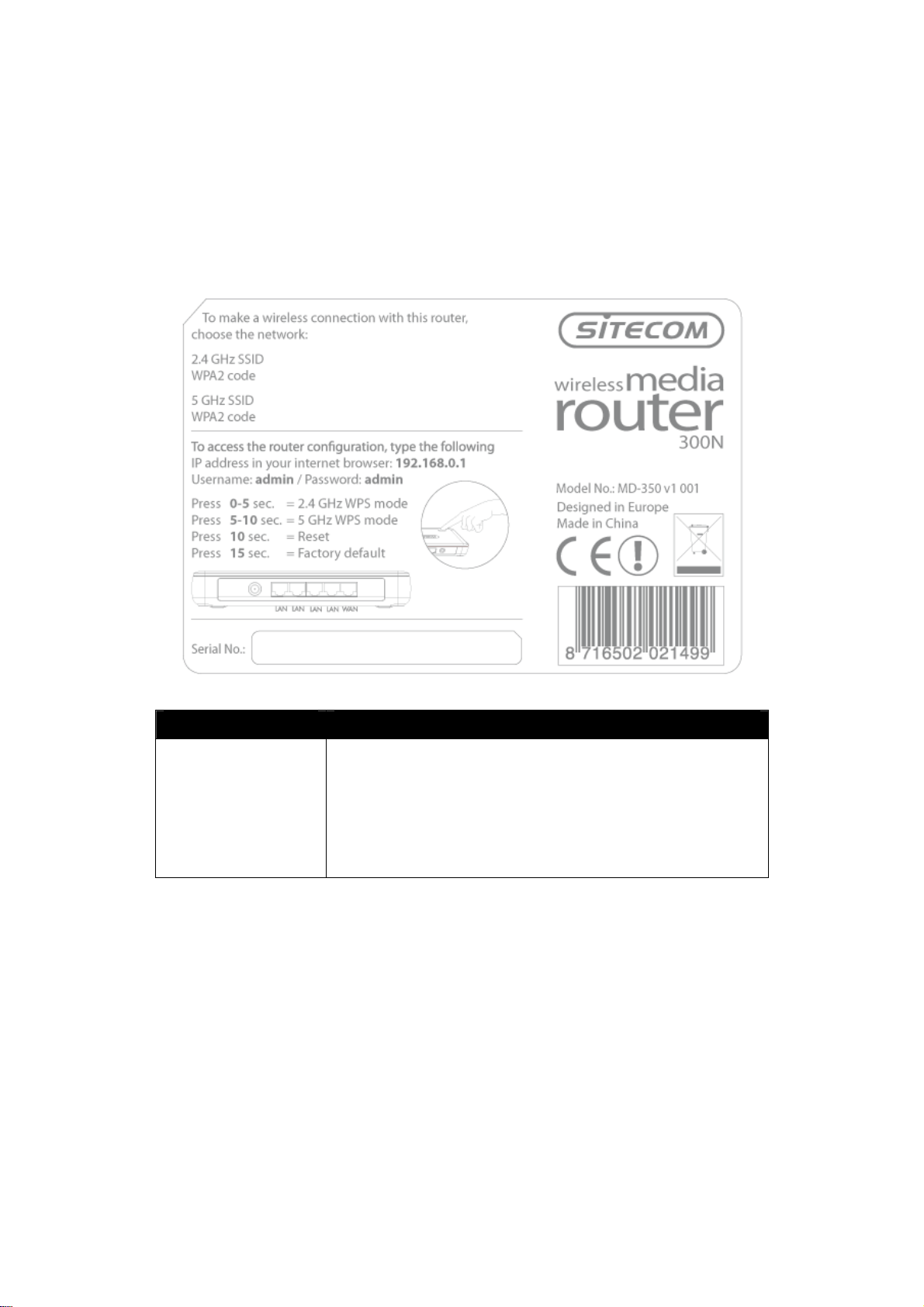
Back label
The backlabel describes the IP address, login details, SSID, security code and WPS
button functionality.
Button Description
WPS BUTTON Press 0-5 seconds for 2.4 GHz WPS mode
Press 5-10 seconds for 5 GHz WPS mode
Press 10 seconds to reset the router
Press 15 Seconds to reset the router to factory
defaults.
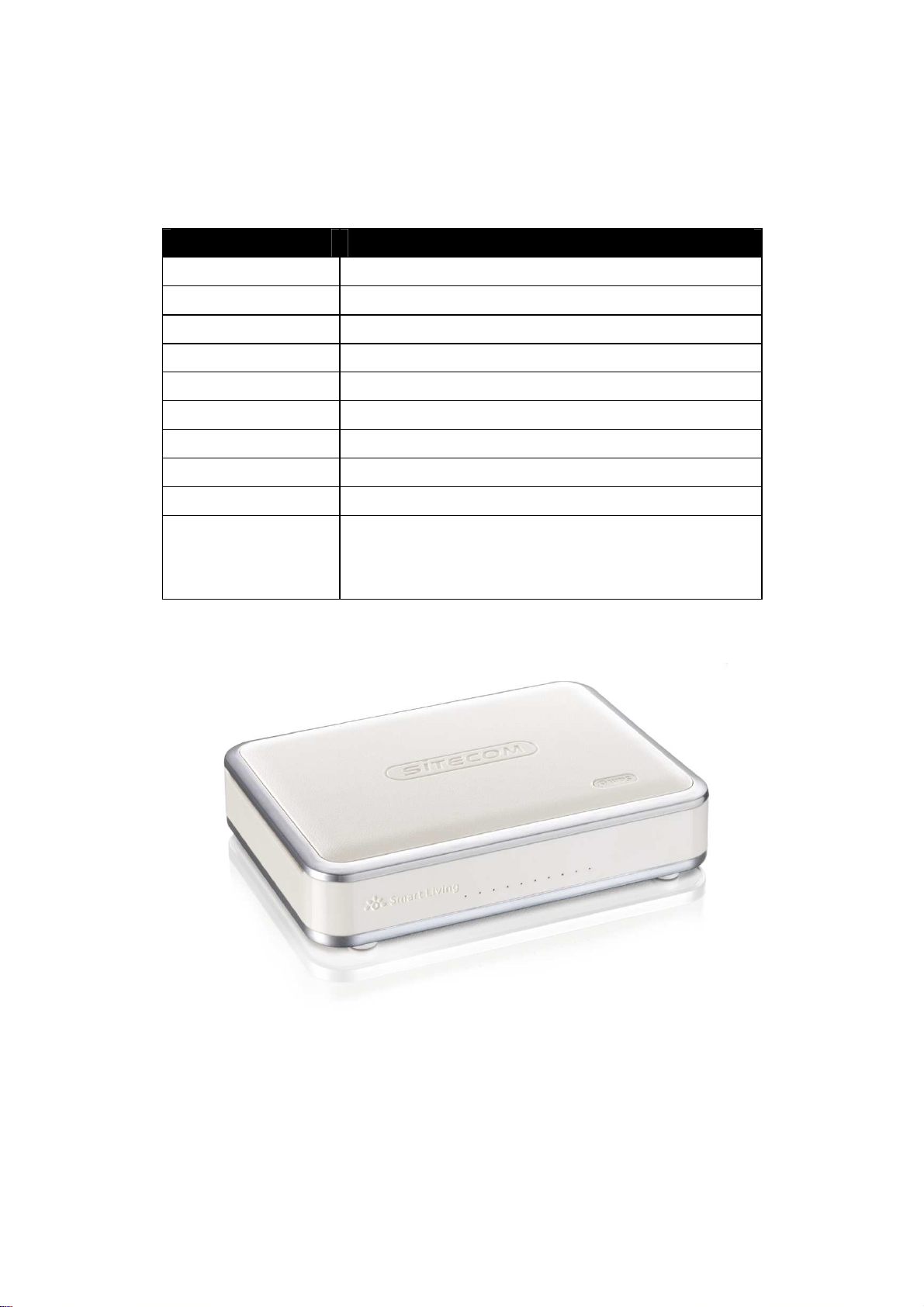
LED Definition
From left to right.
Port Description
Power (Blue) Shows the device is turned on.
USB (Blue) Shows an USB device is connected.
WiFi 2.4 GHz (Blue) Shows WiFi activity on the 2.4 GHz band.
WiFi 2.4 GHz (Blue) Shows WiFi activity on the 2.4 GHz band.
WAN (Blue) Shows the cable is connected.
LAN (Blue) Shows the cable is connected.
LAN (Blue) Shows the cable is connected.
LAN (Blue) Shows the cable is connected.
LAN (Blue) Shows the cable is connected.
WPS (Blue) Shows WPS activity after pushing WPS button.
Flashing = In progress
Solid = success

System Requirements
The following are the minimum system requirements in order configure the
device:
- PC/Notebook
- Operating System – Microsoft Windows XP/2000/Vista/Seven
- 1 Free Ethernet port
- Wi-Fi card/USB dongle (802.11 b/g/n) – optional
- External xDSL (ADSL) or Cable modem with an Ethernet port (RJ-45)
- PC with a web-browser (Internet Explorer, Safari, Firefox, Opera)
- Ethernet compatible CAT5 cables
-
1 Understanding the Hardware
Hardware Installation
You can place the WL-350 on a desk or other flat surface, or you can mount it on
a wall. For optimal performance, place your Wireless Broadband Router in the
center of your office (or your home) in a location that is away from any potential
source of interference, such as a metal wall or microwave oven. This location
must be close to a power connection and your ADSL/Cable modem.
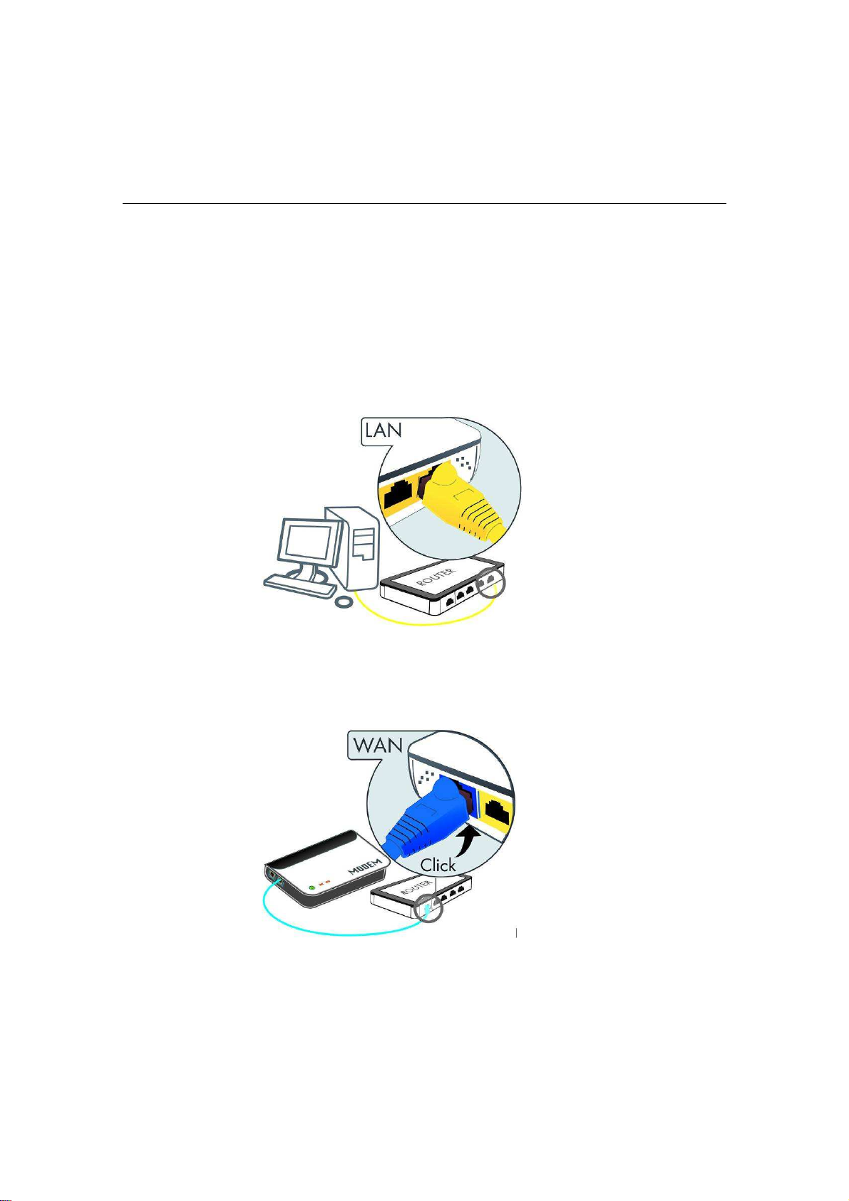
Plug one end of the Ethernet cable into the LAN port of the device and another
end into your PC/Notebook.
Plug one end of another Ethernet cable to the WAN port of the device and the
other end into you cable/DSL modem (Internet).
Insert the DC-outlet of the power adapter into the port labeled “DC-IN” and the
other end into a power socket on the wall.
IP Address Configuration
This device can be configured as a Bridge/Router or Access Point. The default IP
address of the device is 192.168.0.1. In order to log into this device, you must first
configure the TCP/IP settings of your PC/Notebook.
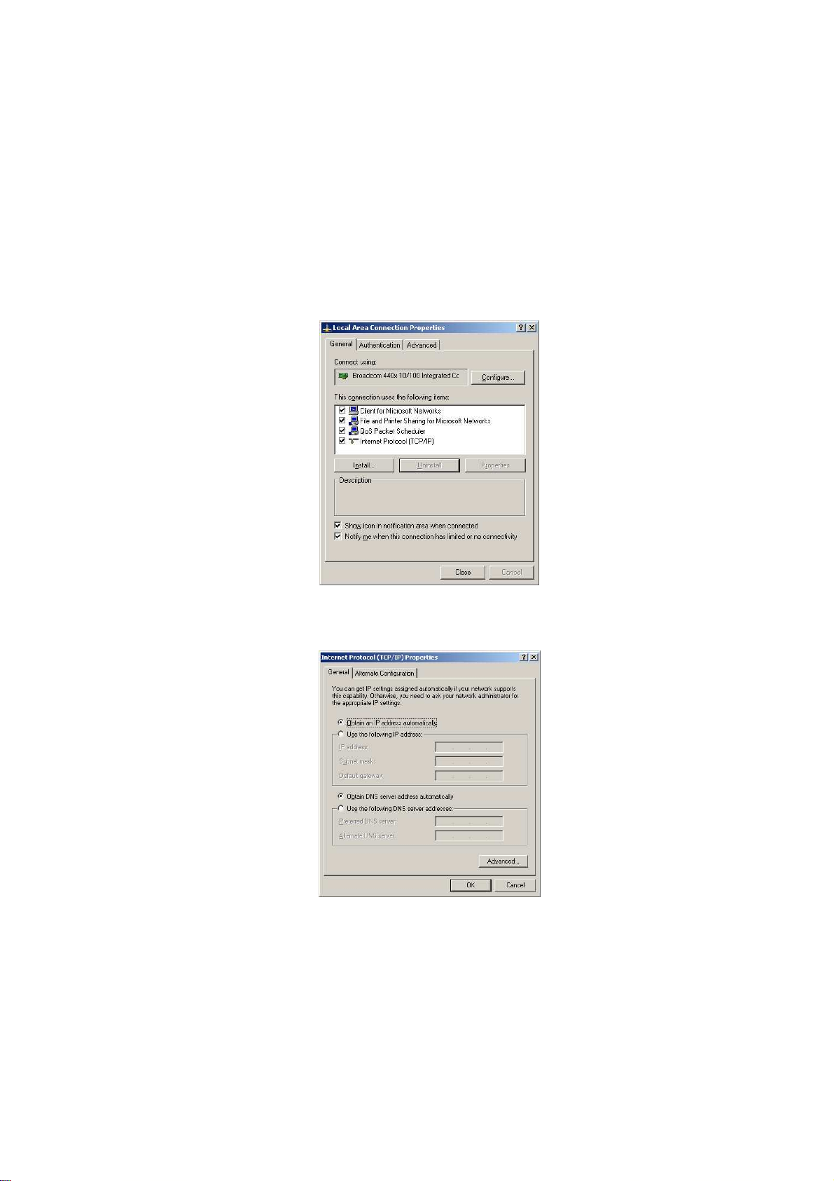
1. In the control panel, double click Network Connections and then double click
on the connection of your Network Interface Card (NIC). You will then see the
following screen.
2. Select Internet Protocol (TCP/IP) and then click on the Properties button.
This will allow you to configure the TCP/IP settings of your PC/Notebook.
Select both [Obtain an IP address automatically] and [Obtain DNS
server address automatically].
3. Click on the OK button to close this window, and once again to close LAN
properties window.
Username:
admin
2 Internet Connection Wizard
This device offers a quick and simple configuration through the use of a wizard.
This chapter describes how to use the wizard to configure the internet settings.
Please refer to Chapter 6 in order to configure the more advanced features of the
device.
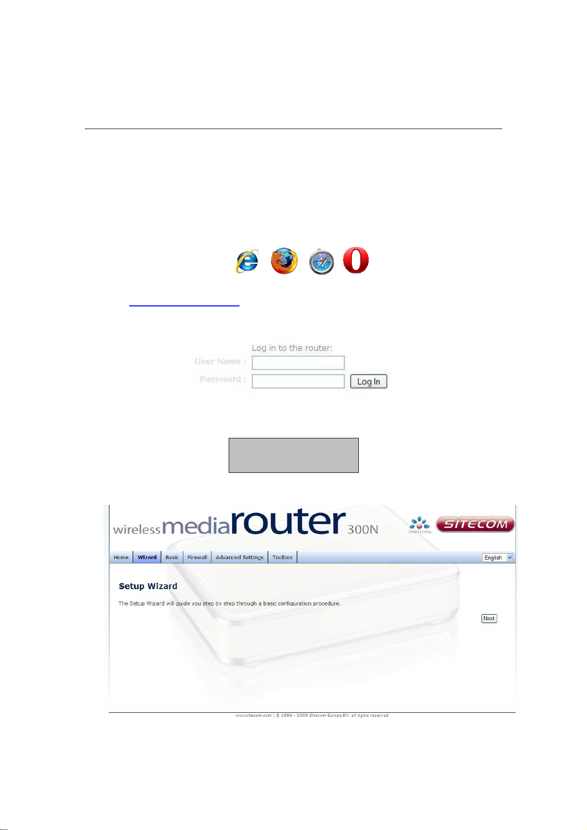
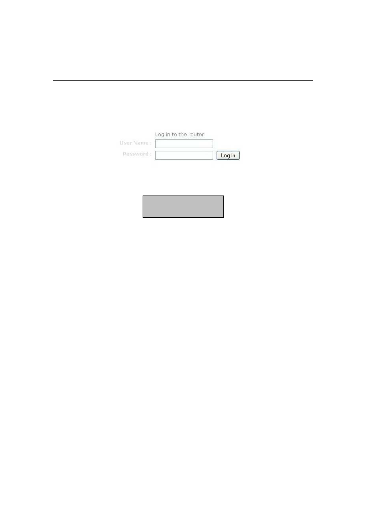
Logging In
To configure the device, open a web browser.
Type
http://192.168.0.1
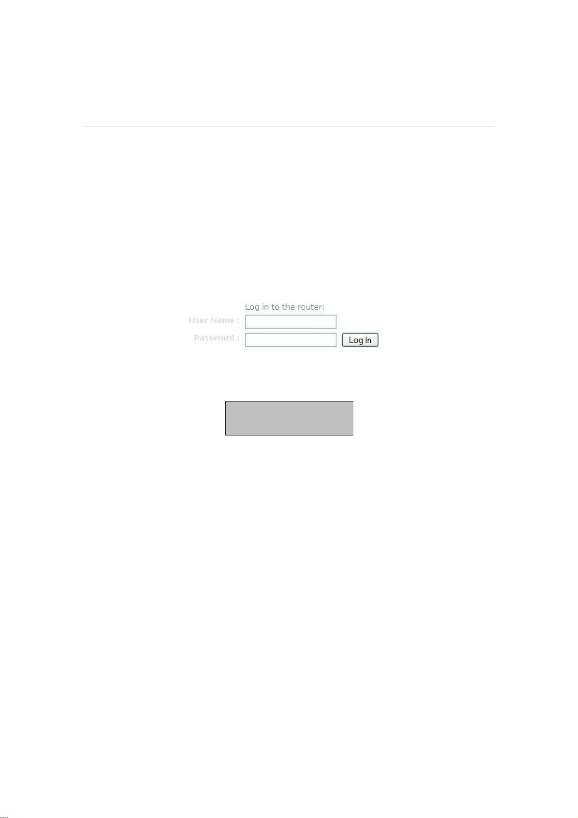
After connecting to the IP address, the web-browser will display the login page.
Fill in the username and password. The default credentials are shown below:
Click on the Wizard button to begin the process.
in the address bar and press [Enter].
Password: admin
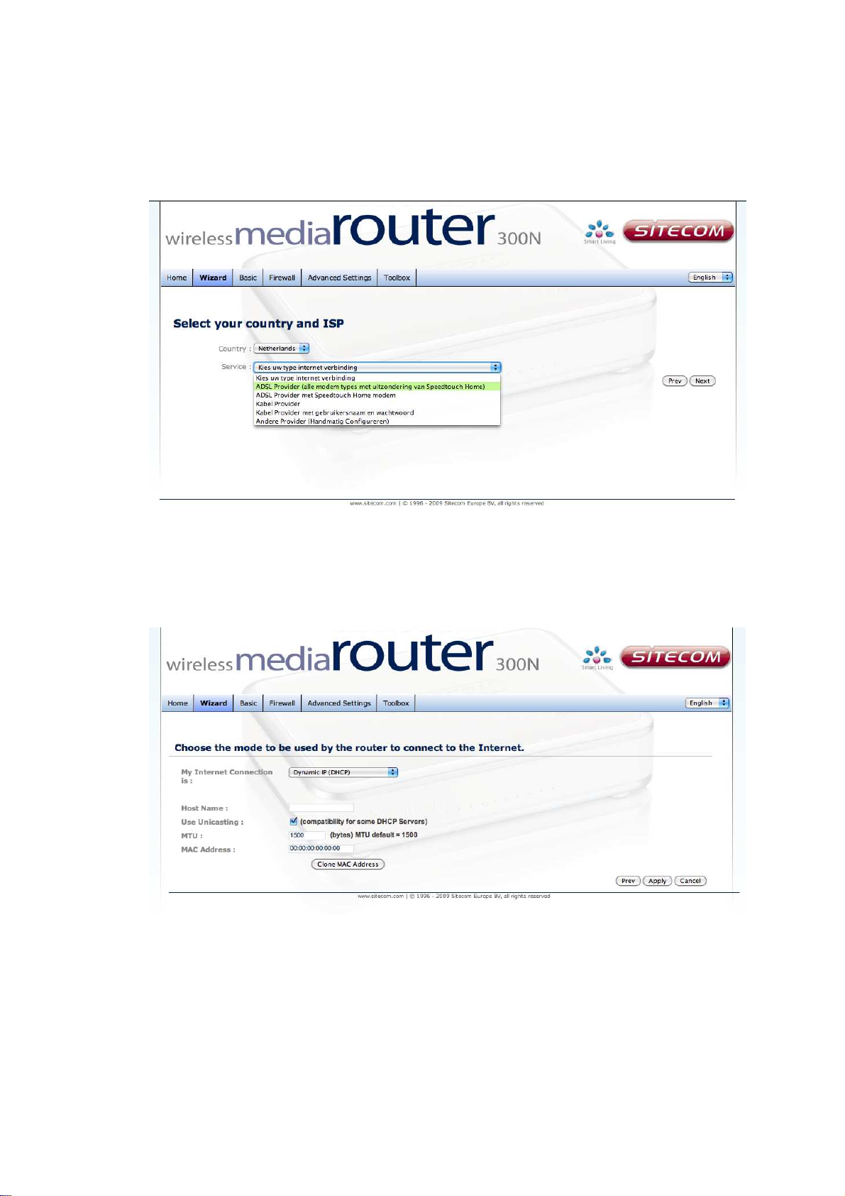
Select your country from the Country list. Select your internet provider. Click
Next.
Depending on the chosen provider, you may need to enter your user name and
password, MAC address or hostname in the following window. After you have
entered the correct information, click Next.
Click APPLY to complete the configuration.
3 Wi-Fi Protected Setup Wizard
Wi-Fi Protected Setup is a feature that locks the wireless security settings and
prevents the settings from being changed by any new external registrar using its
PIN. Devices can still be added to the wireless network using Wi-Fi Protected
Setup.
Please refer to Chapter 5 in order to configure the more advanced features of the
device
Logging In
Open a web browser and type in the IP address (default: http://192.168.0.1),
the web-browser will display the login page.
Fill in the username and password. The default credentials are shown below:
Username: admin
Password: admin
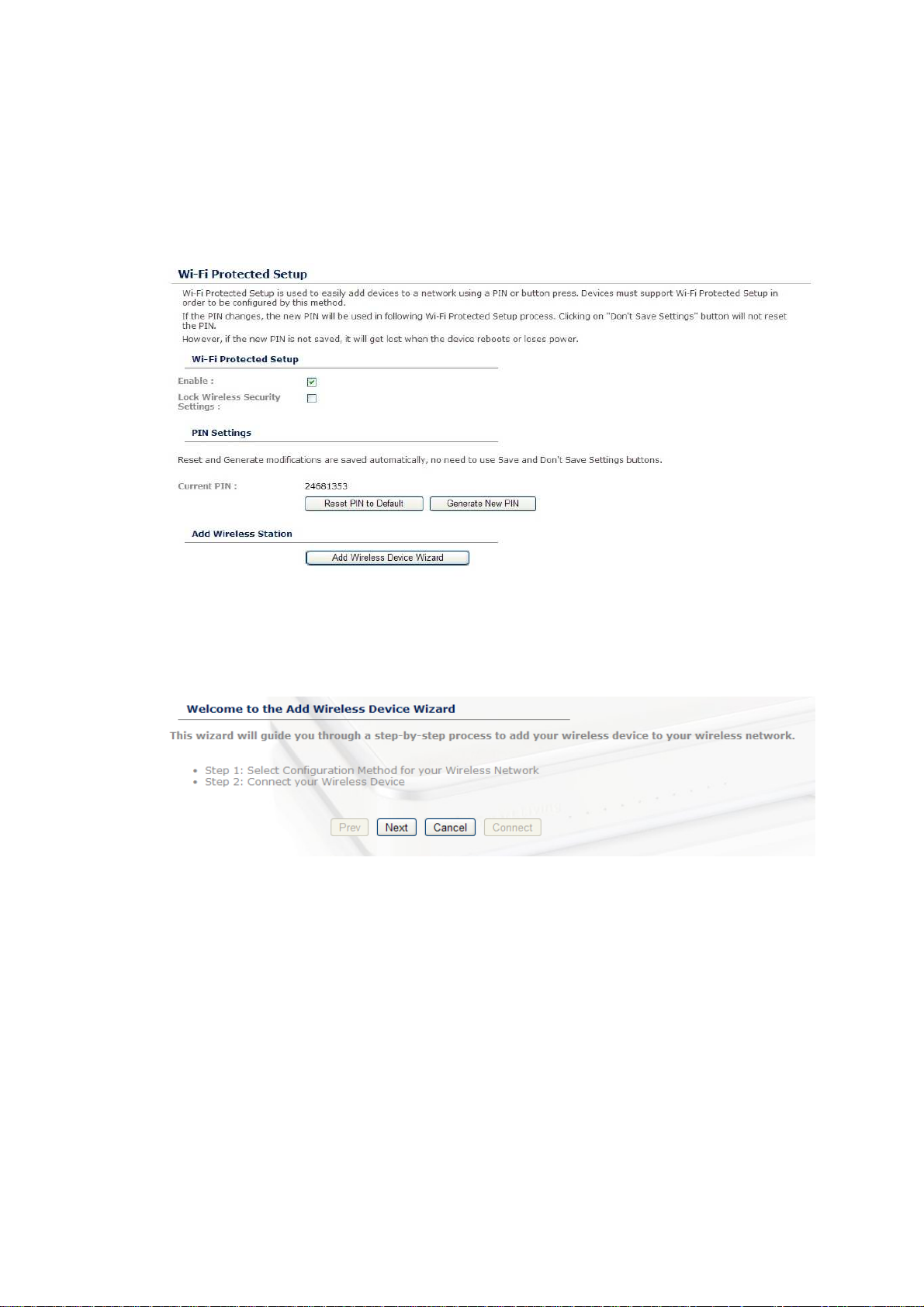
Add a Wireless Device
Click on Basic -> Wireless and click on the Add Wireless Device Wizard
button.
The wireless wizard will inform you that there are two major steps in the process.
o Select the configuration method for your wireless network
o Connect your wireless device
Click on the Next button to continue.
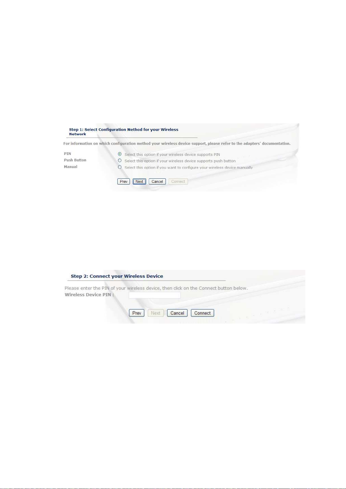
You may select from three available options:
o PIN: Select this radio button if your wireless device supports PIN
o Push Button: Select this radio button if your wireless device supports
push button.
o Manual: Select the radio button if you would like to setup your
wireless device manually. Refer to chapter 5 in order to manually
configure the device.
The wizard will either display the wireless network settings to guide you through
manual configuration, prompt you to enter the PIN for the device, or ask you to
press the configuration button on the device. If the device supports Wi-Fi
Protected Setup and has a configuration button, you can add it to the network by
pressing the configuration button on the device and then the on the router within
60 seconds. The status LED on the router will flash three times if the device has
been successfully added to the network.
There are several ways to add a wireless device to your network. Access to the
wireless network is controlled by a registrar. A registrar only allows devices onto
the wireless network if you have entered the PIN, or pressed a special Wi-Fi
Protected Setup button on the device. The router acts as a registrar for the
network, although other devices may act as a registrar as well.
Using the PIN
A PIN is a unique number that can be used to add the router to an existing
network or to create a new network. The default PIN may be printed on the
bottom of the router. For extra security, a new PIN can be generated. You can
restore the default PIN at any time. Only the Administrator ("admin" account) can
change or reset the PIN.
Select the PIN radio button and then click on the Next button.
Specify the PIN and then click on the Connect button.
The wireless device configuration is now complete.
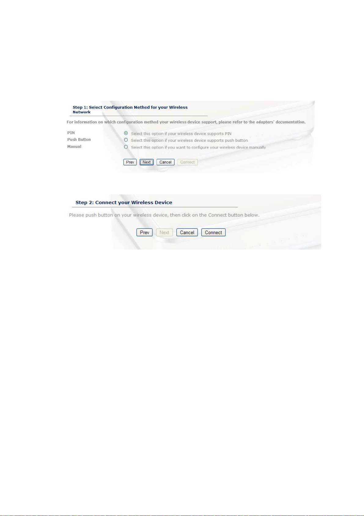
Using the Push Button
WPS is used for Wi-Fi Protected Setup. By pressing the WPS button on the top
panel of the device, the security settings of the device will automatically
synchronize with other wireless devices on your network that support Wi-Fi
Protected Setup
If the device supports Wi-Fi Protected Setup and has a configuration button, you
can add it to the network by pressing the configuration button on the device and
then the one the router within 60 seconds. The status LED on the router will flash
three times if the device has been successfully added to the network.
Select the Push Button radio button and then click on the Next button.
Press the WPS button on the device (which is located on the left side of the front
panel) and then click on the Next button.
Username:
admin
4 Advanced Web Configuration
Logging In
Open a web browser and type in the IP address (default: http://192.168.0.1),
the web-browser will display the login page.
Fill in the username and password. The default credentials are shown below:
After logging in you will see the graphical user interface (GUI) of the device. The
navigation menu on the top is divided into six main sections:
1. Home: This shows the basic status of the router.
2. Wizard: The setup wizard which will guide you through the initial setup.
3. Basic: This menu includes the network settings, wireless settings and WAN
settings.
4. Firewall: This menu includes virtual server, special applications, port
forwarding, access control, etc.
5. Advanced Settings: This menu includes DDNS, the Stream engine, MAC
address filter, web filter etc.
6. Toolbox: This menu displays the Time zone, Firmware update, Password
settings etc.
Password: admin
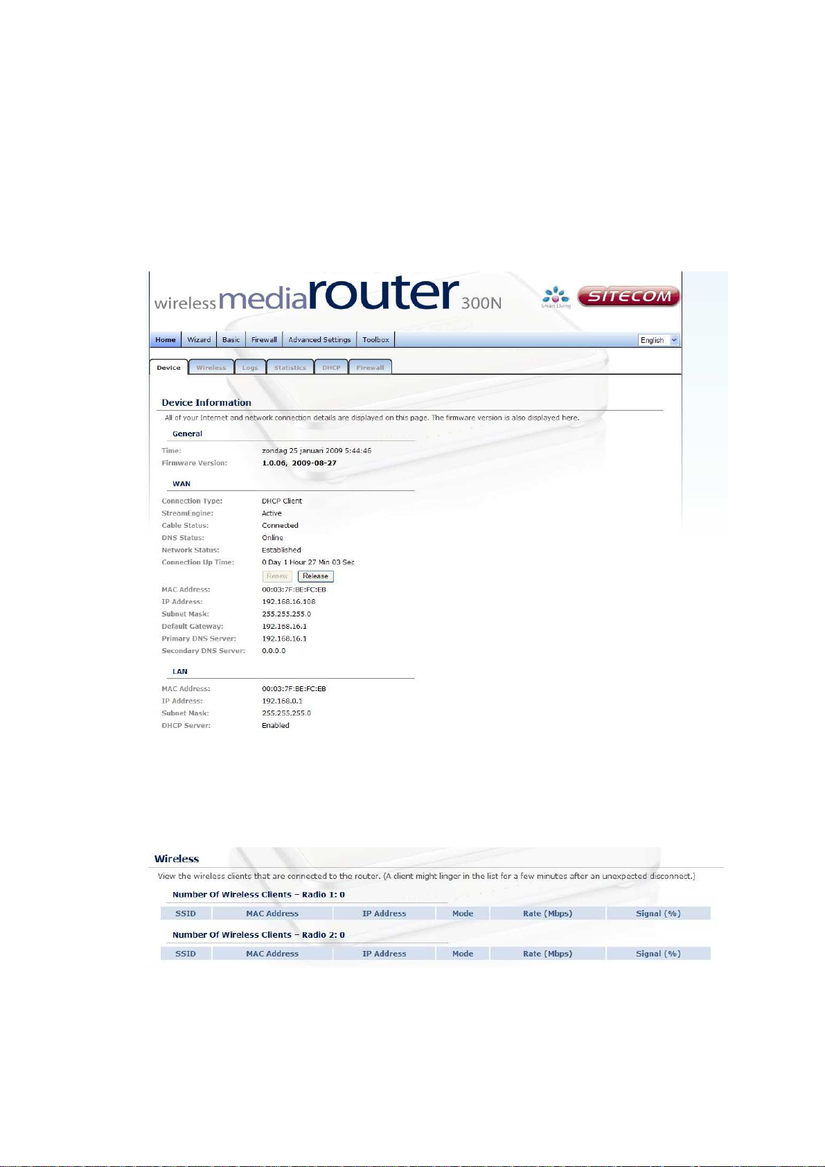
4.1 Home
Device
All of your Internet and network connection details are displayed on this page.
The firmware version is also displayed here.
Wireless
Click on the Wireless link in the navigation menu. The wireless section allows
you to view the wireless clients that are connected to the device.
- MAC Address: The Ethernet ID (MAC address) of the wireless client.
- IP Address: The LAN-side IP address of the client.

- Mode: The transmission standard being used by the client. Values are
11a, 11b, 11g, or 11n for 802.11a, 802.11b, 802.11g, or 802.11n
respectively.
- Rate: The actual transmission rate of the client in megabits per second.
- Signal: This is a relative measure of signal quality. The value is
expressed as a percentage of theoretical best quality. Signal quality can
be reduced by distance, by interference from other radio-frequency
sources (such as cordless telephones or neighboring wireless networks),
and by obstacles between the router and the wireless device.
WISH
The WISH Sessions page displays full details of active local wireless sessions
through your router when WISH has been enabled. A WISH session is a
conversation between a program or application on a wirelessly connected
LAN-side computer and another computer, however connected.
- Originator: The IP address and, where appropriate, port number of the
computer that originated a network connection.
- Target: The IP address and, where appropriate, port number of the
computer to which a network connection has been made.
- Protocol: The communications protocol used for the conversation.
- State: State for sessions that use the TCP protocol.
o NO: None -- This entry is used as a placeholder for a future
connection that may occur.
o SS: SYN Sent -- One of the systems is attempting to start a
connection.
o EST: Established -- the connection is passing data.
o FW: FIN Wait -- The client system has requested that the connection
be stopped.
o CW: Close Wait -- the server system has requested that the
connection be stopped.
o TW: Time Wait -- Waiting for a short time while a connection that was
in FIN Wait is fully closed.
o LA: Last ACK -- Waiting for a short time while a connection that was in
Close Wait is fully closed.
o CL: Closed -- The connection is no longer active but the session is
being tracked in case there are any retransmitted packets still pending.
- Priority: The priority given to packets sent wirelessly over this
conversation by the WISH logic. The priorities are:
o BK: Background (least urgent).
o BE: Best Effort.
o VI: Video.
o VO: Voice (most urgent).
- Time Out: The number of seconds of idle time until the router considers
the session terminated. The initial value of Time Out depends on the type
and state of the connection.
o 300 seconds - UDP connections.
o 240 seconds - Reset or closed TCP connections. The connection does
not close instantly so that lingering packets can pass or the connection
can be re-established.
o 7800 seconds - Established or closing TCP connections.
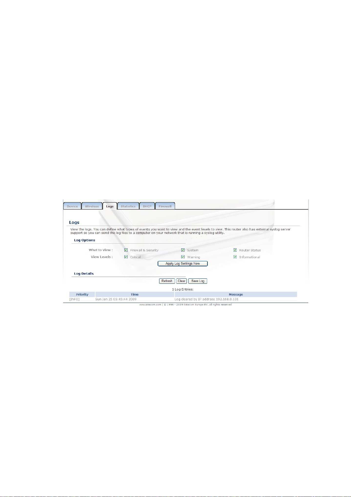
Logs
Click on the Logs link in the navigation menu. The router automatically logs
(records) events of possible interest in its internal memory. If there is not enough
internal memory for all events, logs of older events are deleted, but logs of the
latest events are retained. The Logs option allows you to view the router logs.
You can define what types of events you want to view and the level of events to
view. This router also has external Syslog Server support so you can send the log
files to a computer on your network that is running a Syslog utility.
- What to View: Select the features of which you would like to view the
logs: Firewall & Security, System, or Router Status.
- View Levels: Select the warning levels for the logs: Critical, Warning, or
Informational.
- Click on the Apply Log Settings Now to make the new log effective.
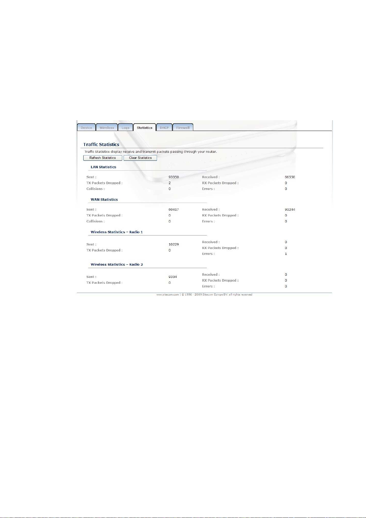
Stats
Click on the Statistics link in the navigation menu. This page displays the
transmitted and received packet statistics of the wired (LAN & WAN) and wireless
interface. Click on the Refresh button to refresh the statistics.
 Loading...