

Sitecom WL-153 WIRELESS BROADBAND ROUTER FM

Wireless Network
Broadband Router MiMoXR
WL-153
Full manual
1

Copyright
The contents of this publication may not be reproduced in any part or as a whole, stored,
transcribed in an information retrieval system, translated into any language, or transmitted
in any form or by any means, mechanical, magnetic, electronic, optical, photocopying, manual,
or otherwise, without the prior written permission.
Trademarks
All products, company, brand names are trademarks or registered trademarks of their
respective companies. They are used for identification purpose only. Specifications are subject
to be changed without prior notice.
FCC Interference Statement
This equipment has been tested and found to comply with the limits for a Class B digital device
pursuant to Part 15 of the FCC Rules. These limits are designed to provide reasonable
protection against radio interference in a commercial environment. This equipment can
generate, use and radiate radio frequency energy and, if not installed and used in accordance
with the instructions in this manual, may cause harmful interference to radio communications.
Operation of this equipment in a residential area is likely to cause interference, in which case
the user, at his own expense, will be required to take whatever measures are necessary to
correct the interference.
CE Declaration of Conformity
This equipment complies with the requirements relating to electromagnetic compatibility, EN
55022/A1 Class B.
The specification is subject to change without notice.
2

Table of Contents
CHAPTER 1 INTRODUCTION ............................................................................... 5
1.1 FEATURES.................................................................................................... 5
1.2 MINIMUM REQUIREMENTS .......................................................................... 6
1.3 PACKAGE CONTENT ..................................................................................... 6
CHAPTER 2 HARDWARE INSTALLATION ............................................................. 7
2.1 PANEL LAYOUT .............................................................................................. 7
2.1.1 FRONT LEDS............................................................................... FOUT! BLADWIJZER NIET GEDEFINIEERD.
2.1.2. REAR PANEL................................................................................................................................................. 8
2.2 PROCEDURE FOR HARDWARE INSTALLATION................................................ 9
2.2.1 DECIDE WHERE TO PLACE YOUR WIRELESS BROADBAND ROUTER ............................................................... 9
2.2.2 SETUP LAN CONNECTION ............................................................................................................................. 9
2.2.3 SETUP WAN CONNECTION ............................................................................................................................ 9
2.2.4 POWER ON..................................................................................................................................................... 9
CHAPTER 3 NETWORK SETTINGS AND SOFTWARE INSTALLATION ................... 10
3.1 MAKE THE CORRECT NETWORK SETTINGS FOR YOUR PC ............................. 10
CHAPTER 4 CONFIGURING WIRELESS BROADBAND ROUTER ........................... 12
4.1 START-UP AND LOG IN ................................................................................ 13
4.2 STATUS ........................................................................................................ 14
4.2.1 LAN SETTINGS ........................................................................................................................................... 15
4.2.2 DEVICE STATU S ........................................................................................................................................... 17
4.2.3 INTERNET STATU S ....................................................................................................................................... 18
4.2.4 DHCP CLIENT STATUS ................................................................................................................................19
4.2.5 SYSTEM LOG ............................................................................................................................................... 20
4.2.6 STATI ST IC S .................................................................................................................................................. 21
5. RUN SETUP WIZARD ...................................................................................... 22
CHAPTER 6 WIRELESS SETTINGS.................................................................. 24
6.1 WIRELESS BASIC SETTINGS ........................................................................ 24
6.2 ADVANCED WIRELESS SETTINGS................................................................. 25
6.3 WIRELESS SECURITY OPTIONS.................................................................... 26
3

6.3.1 WEP E
NCRYPTION ...................................................................................................................................... 26
6.3.2 802.1X ONLY ............................................................................................................................................... 28
6.3.3 WPA PRE-SHARED KEY ............................................................................................................................... 29
6.3.4 WPA RADIUS .............................................................................................................................................. 29
6.4 ACCESS CONTROL ........................................................................................ 31
CHAPTER 7 FIREWALL SETTINGS................................................................... 32
7.1 DMZ ............................................................................................................. 32
7.2 DOS ATTACK ................................................................................................ 33
7.3 ACCESS CONTROL ........................................................................................ 34
7.4 URL BLOCK................................................................................................... 35
CHAPTER 8 ADVANCED SETTINGS................................................................. 37
8.1 PORT FORWARDING .................................................................................... 37
8.2 VIRTUAL SERVER ......................................................................................... 38
8.3 SPECIAL APPLICATIONS .............................................................................. 40
8.4 ALG SETTINGS ............................................................................................. 42
8.5 UPNP SETTINGS........................................................................................... 42
8.6 QOS ............................................................................................................. 43
CHAPTER 9 TOOLS ......................................................................................... 46
9.1 TIMEZONE.................................................................................................... 47
9.2 REMOTE MANAGEMENT ................................................................................ 48
9.3 FIRMWARE UPGRADE................................................................................... 49
9.4 BACK-UP SETTINGS ..................................................................................... 50
9.5 RESET (RESTART) THE ROUTER ................................................................... 51
9.6 DDNS ........................................................................................................... 51
APPENDIX A ...................................................................................................... 52
GLOSSARY ......................................................................................................... 53
4

Chapter 1 Introduction
Congratulations on purchasing this Wireless Broadband Router. This Wireless Broadband
Router is a cost-effective IP Sharing Router that enables multiple users to share the Internet
through an ADSL or cable modem. Simply configure your Internet connection settings in the
Wireless Broadband Router and plug your PC to the LAN port and you're ready to share files
and access the Internet. As your network grows, you can connect another hub or switch to the
router’s LAN ports, allowing you to easily expand your network. The Wireless Broadband
Router is embedded with a IEEE 802.11g/b access point that allows you to build up a wireless
LAN. The Wireless Broadband Router provides a total solution for the Small and Medium-sized
Business (SMB) and the Small Office/Home Office (SOHO) markets, giving you an instant
network today, and the flexibility to handle tomorrow's expansion and speed.
1.1 Features
• High Internet Access throughput (50M)
• Allow multiple users to share a single Internet line
• Supports up to 253 users
• Internet Access via Cable or xDSL modem
• Access Private LAN Servers from the Public Network
• Equipped with four LAN ports (10/100M) and one WAN port (10/100M)
• Provides IEEE 802.11g/b wireless LAN access point
• Support DHCP (Server/Client) for easy setup
• Support advance features such as: Special Applications, DMZ, Virtual Servers, Access
Control, Firewall.
• Allow you to monitor the router’s status such as: DHCP Client Log, System Log,
Security Log and Device/Connection Status
• Easy to use Web-based GUI for configuration and management purposes
• Remote Management allows configuration and upgrades from a remote site (over the
Internet)
5

1.2 Minimum Requirements
•
•
•
One External xDSL (ADSL) or Cable modem with an Ethernet port (RJ-45)
Network Interface Card (NIC) for each Personal Computer (PC)
PCs with a Web-Browser (Internet Explorer 4.0 or higher, or Netscape Navigator 4.7
or h
igher)
1.3 Package Content
• One 4-port Wireless Broadband router unit
• One Quick Installation Guide
• One User Manual CD
• One Power Adapter
• CAT-5 UTP Fast Ethernet Cable
Note
The WAN “idle timeout” auto-disconnect function may not work due to abnormal activities of
some network application software, computer virus or hacker attacks from the Internet. For
example, some software sends network packets to the Internet in the background, even when
you are not using the Internet. So please turn off your computer when you are not using it.
This function also may not work with some ISP. So please make sure this function can work
properly when you use this function in the first time, especially your ISP charge you by time
used.
6

Chapter 2 Hardware Installation
2.1 Panel Layout
LEDs:
LED Function Color Status Description
POWER Power indication Green On Power is being applied to this product.
The corresponding WAN or LAN port is
linked.
The corresponding WAN or LAN port is
sending or receiving data.
The corresponding WAN or LAN port is
sending or receiving data.
Link/
Modem
WLAN Wireless Activity Green
Link Status Green
On
Blinking
On Wireless LAN had been enabled
Blinking Sending or receiving data via wireless.
Blinking
100Mbps
Data Rate
Green
On
Data is transmitting in 100Mbps on the
corresponding LAN port.
7
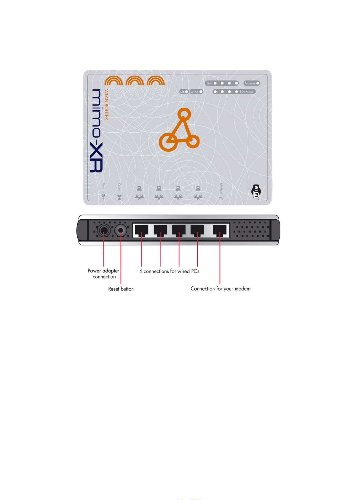
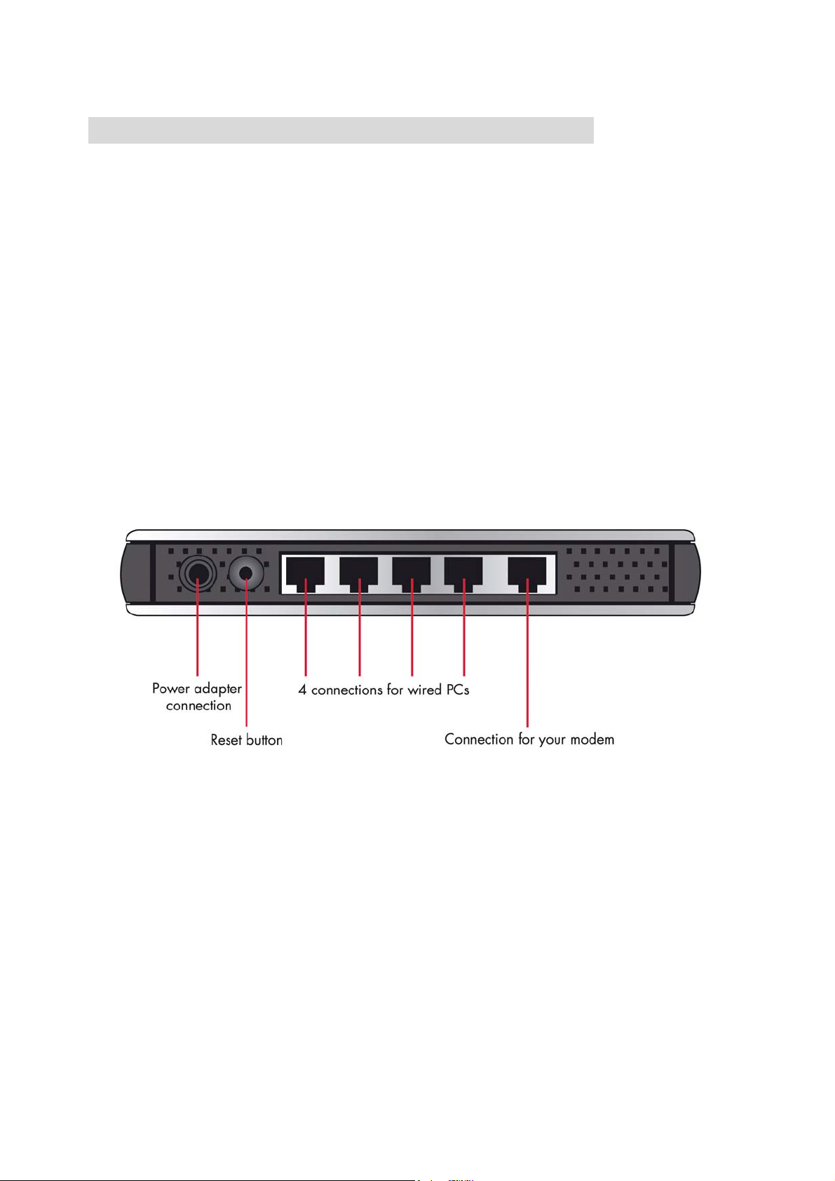
2.1.2. Rear Panel
Ports:
Port Description
POWER Power inlet
Modem the port where you will connect your cable (or DSL) modem
or Ethernet router.
Port 1-4 the ports where you will connect networked computers and
other devices.
To reset system settings to factory defaults, press the reset
button for at least 4 seconds.
Reset
To reboot the device, press the reset button less than 4
seconds.
8
2.2 Procedure for Hardware Installation
2.2.1 Decide where to place your Wireless Broadband Router
Y
ou can place your Wireless Broadband Router on a desk or other flat surface, or you can
m
ount it on a wall. For optimal performance, place your Wireless Broadband Router in the
c
enter of your office (or your home) in a location that is away from any potential source of
in
terference, such as a metal wall or microwave oven. This location must be close to power
a
nd network connection.
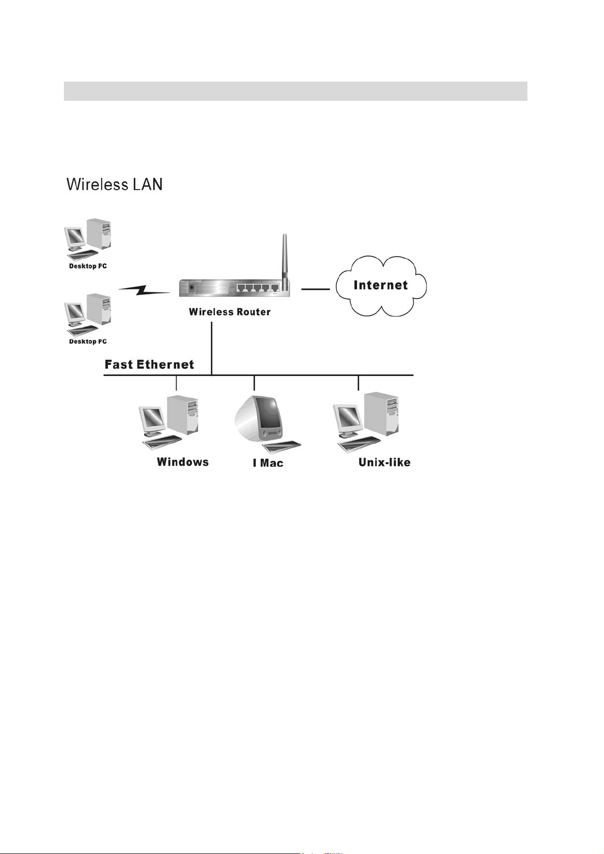
2.2.2 Setup LAN connection
a. Wired LAN connection: connects an Ethernet cable from your computer’s Ethernet port
to one of the LAN ports of this product.
b. Wireless LAN connection: locate this product at a proper position to gain the best
transmit performance.
Figure 2-3 Setup of LAN and WAN connections for this product.
2.2.3 Setup WAN connection
P
repare an Ethernet cable for connecting this product to your cable/xDSL modem or Ethernet
b
ackbone. Figure 2-3 illustrates the WAN connection.
2.2.4 Power on
C
onnecting the power cord to power inlet and turning the power switch on, this product will
a
utomatically enter the self-test phase. When it is in the self-test phase, the Power LED will
n
ot be lighted for about 15 seconds, and then Power will flash 9 times to indicate that the
s
elf-test operation has finished. Finally, power will be lit continuously to indicate that this
p
roduct is in normal operation.
9

Chapter 3 Network Settings and Software
Installation
To use this product correctly, you have to properly configure the network settings of your
computers and install the attached setup program into your MS Windows platform (Windows
95/98/NT/2000).
3.1 Make The Correct Network Settings for your PC
The default IP address of this product is 192.168.0.1, and the default subnet mask is
255.255.255.0. These addresses can be changed on your need, but the default values are
used in this manual. If the TCP/IP environment of your computer has not yet been configured,
you can refer to Appendix A to configure it. For example,
1. configure IP as 192.168.0.100, subnet mask as 255.255.255.0 and gateway as
192.168.0.1, or more easier,
2. configure your computers to load TCP/IP setting automatically, that is, via DHCP server
of this product.
After installing the TCP/IP communication protocol, you can use the ping command to check
if your computer has successfully connected to this product. The following example shows the
ping procedure for Windows 95 platforms. First, execute the ping command
ping 192.168.0.1
If the following messages appear:
Pinging 192.168.0.1 with 32 bytes of data:
Reply from 192.168.0.1: bytes=32 time=2ms TTL=64
a communication link between your computer and this product has been successfully
established. Otherwise, if you get the following messages,
Pinging 192.168.0.1 with 32 bytes of data:
Request timed out.
There must be something wrong in your installation procedure. You have to check the
following items in sequence:
10

1. Is the Ethernet cable correctly connected between this product and your computer?
Tip: The LAN LED of this product and the link LED of network card on your computer must
be lighted.
2. Is the TCP/IP environment of your computers properly configured?
Tip: If the IP address of this product is 192.168.0.1, the IP address of your computer
must be 192.168.0.X and default gateway must be 192.168.0.1.
11
Chapter 4 Configuring Wireless Broadband Router
This product provides Web based configuration scheme, that is, configuring by your Web
browser, such as Netscape Communicator or Internet Explorer. This approach can be adopted
in any MS Windows, Macintosh or UNIX based platforms.
12
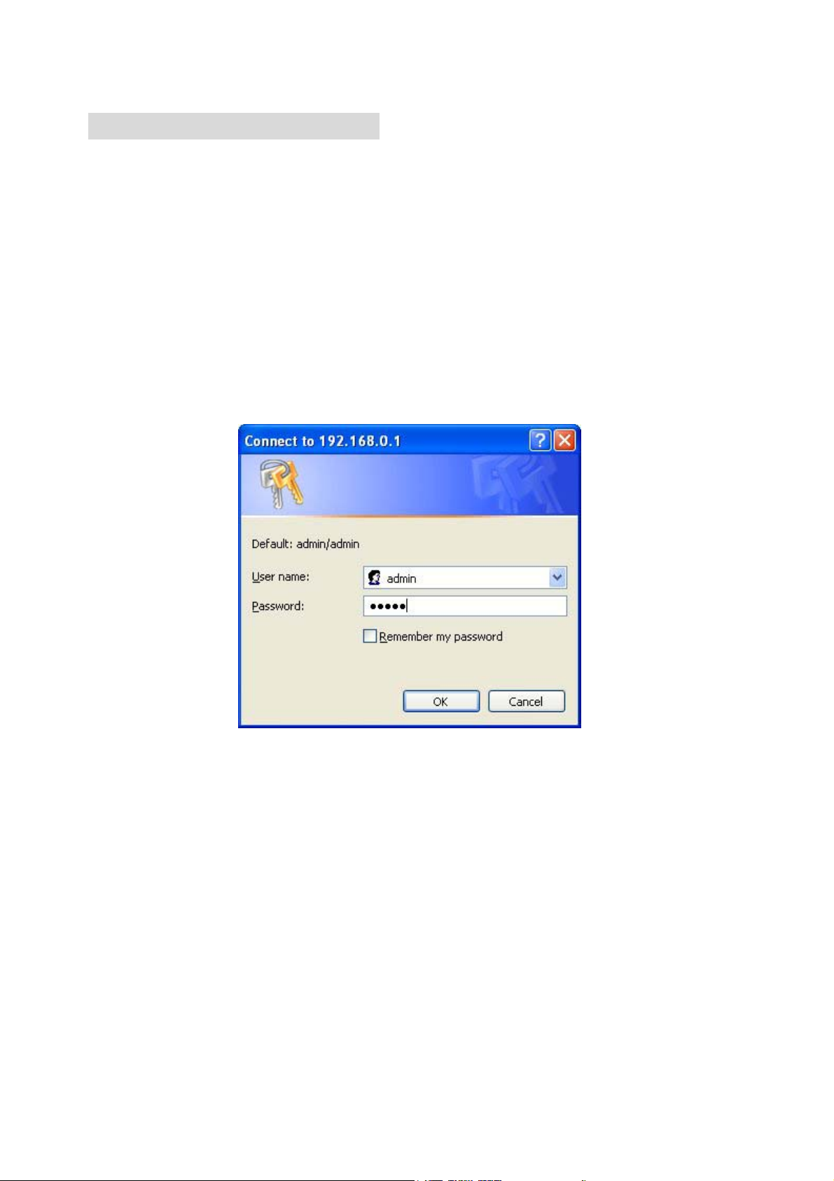
4.1 Start-up and Log in
Activate your browser, and disable the proxy or add the IP address of this product into
the exceptions. Then, type this product’s IP address in the Location (for Netscape) or
Address (for IE) field and press ENTER. For example: http://192.168.0.1.
After the connection is established, you will see the web user interface of this product. There
are two appearances of web user interface: for general users and for system administrator.
To log in as an administrator, enter your login name and password (default: admin/admin) and
click OK. If the password is correct, the web appearance will be changed into administrator
configure mode. As listed in its main menu, there are several options for system
administration.
13
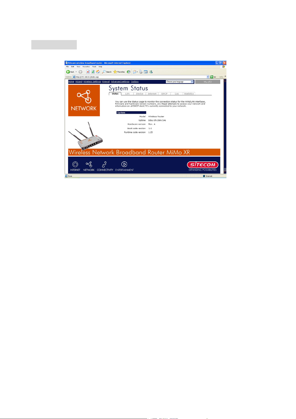
4.2 Status
The Status section allows you to monitor the current status of your router. You can use the
Status page to monitor: the connection status of the Broadband router's WAN/LAN interfaces,
the current firmware and hardware version numbers, any illegal attempts to access your
network, and information on all DHCP client PCs currently connected to your network.
14
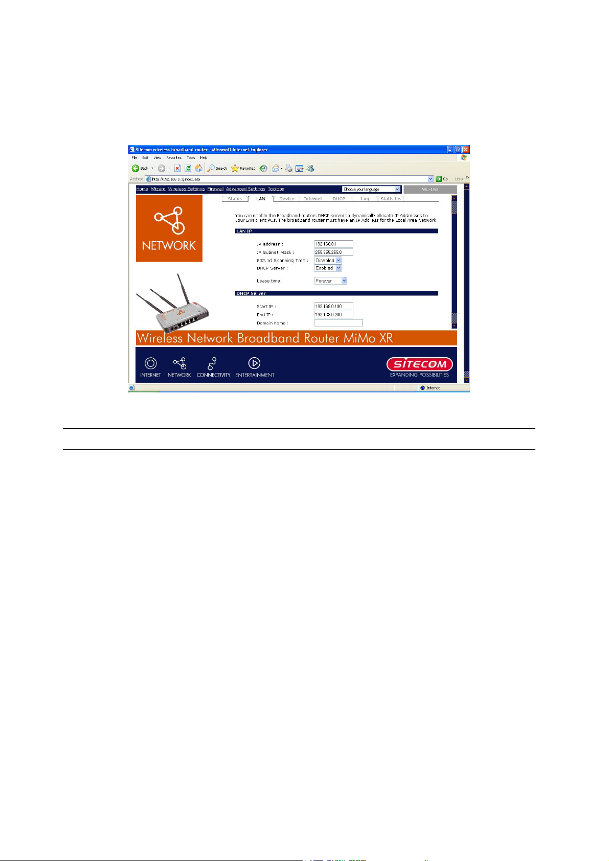
4.2.1 LAN Settings
The LAN Port screen below allows you to specify a private IP address for your router’s LAN
ports as well as a subnet mask for your LAN segment.
Parameters Default Description
IP address 192.168.0.1 Thi s is th e rout e r’s LA N po rt IP a ddre s s (Yo ur LAN
clients default gateway IP address)
IP Subnet Mask 255.255.255.0 Specify a Subnet Mask for your LAN segment
802.1d Spanning Tree Disabled If 802.1d Spanning Tree function is enabled, this
router will use the spanning tree protocol to
prevent network loops.
DHCP Server Enabled You can enable or disable the DHCP server. By
Enabling DHCP server the router will
automatically give your LAN clients an IP address.
Lease Time Forever The DHCP when enabled will temporarily give
your LAN clients an IP address. In the Lease Time
setting you can specify the time period that the
DHCP lends an IP address to your LAN clients. The
DHCP will change your LAN client’s IP address
when this time threshold period is reached
15

IP Address Pool You can select a particular IP address range for your DHCP server to
issue IP addresses to your LAN Clients.
Note: By default the IP range is from: Start IP 192.168.0.100
IP 192.168.0.199. If you want your PC to have a static/fixed IP
address then you’ll have to choose an IP address outside this IP
address Pool
Domain Name You can specify a Domain Name for your LAN
Click <Apply> at the bottom of the screen to save the above configurations. You can now
configure other advance sections or start using the router (with the advance settings in place).
to End
16
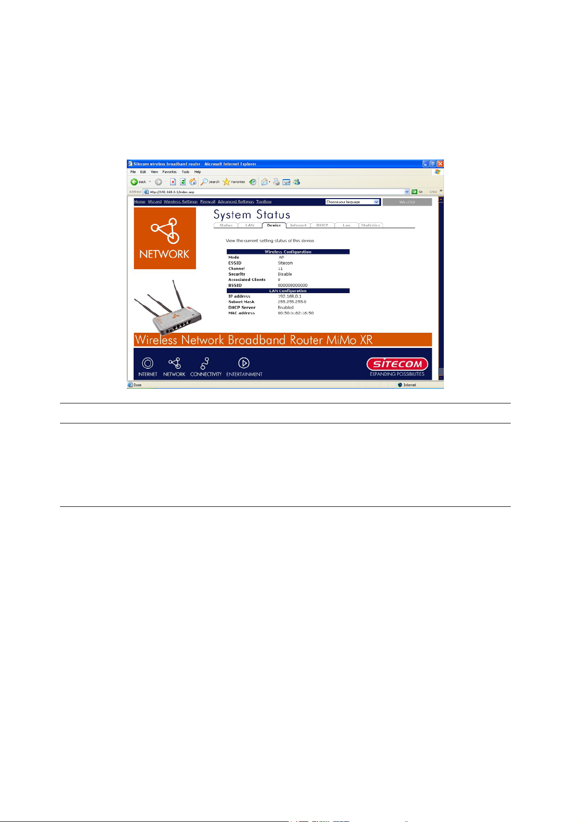
4.2.2 Device Status
View the Broadband router’s current configuration settings. The Device Status displays the
configuration settings you’ve configured in the Wizard/Basic Settings/Wireless Settings
section.
Parameters Description
Device Status This page displays the Broadband router LAN port’s current LAN
IP Address and Subnet Mask. It also shows whether the
DHCP Server function is enabled/disabled..
17
 Loading...