

Page 1
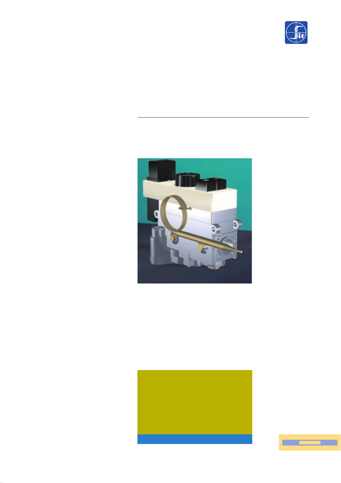
710 MINISIT
THERMOELECTRIC FLAME SUPERVISION DEVICE
PRESSURE REGULATOR
TEMPERATURE CONTROL
SIT Group
PIN 0085AQ0287
MULTI-FUNCTIONAL GAS CONTROL
Page 2

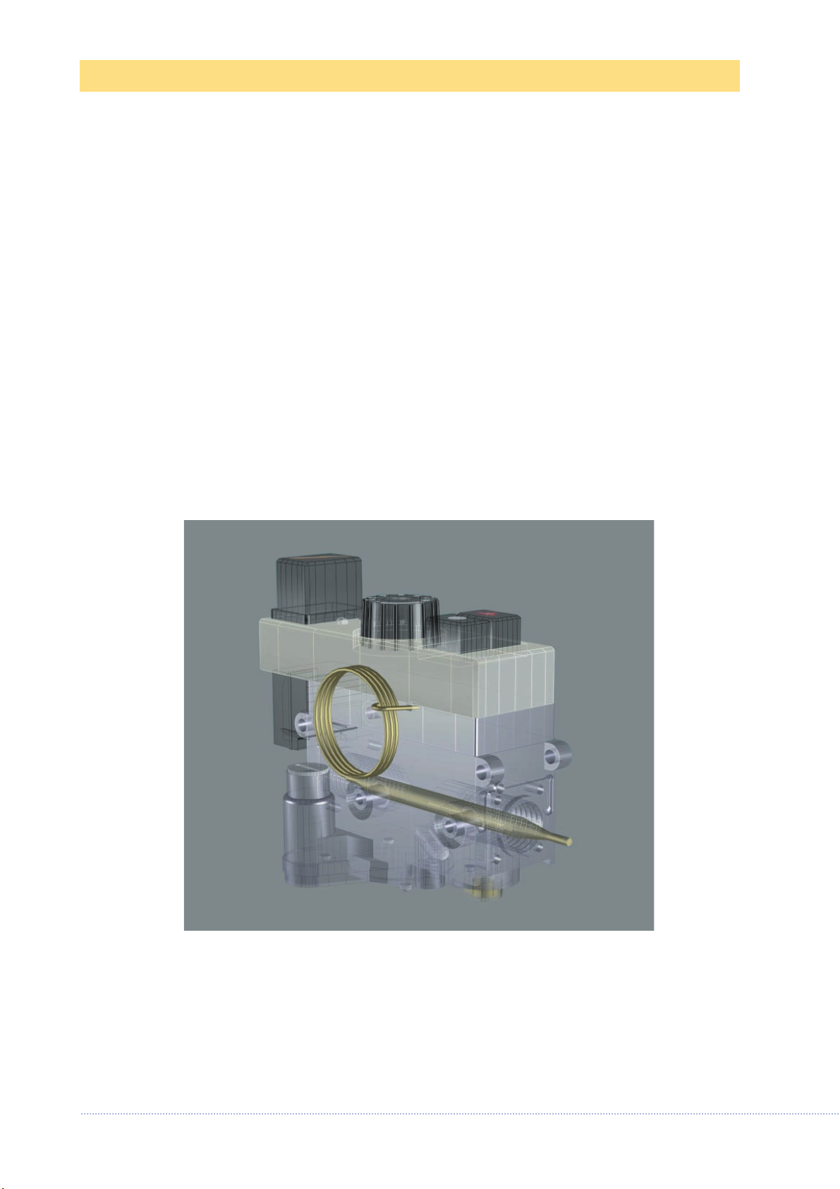
MAIN FEATURES
Multi-functional control
incorporating thermoelectric
flame supervision device with
restart interlock, pressure
regulator or flow adjuster,
modulating thermostat with
on/off snap function.
MULTI-FUNCTIONAL CONTROL
WITH THERMOSTAT
Thermoelectric safety device.
Shut-down device with pilot restart interlock.
Direct acting thermostat with modulation between minimum & maximum setting and on/off
snap function.
Pilot gas rate adjuster.
Pressure regulator (optional).
Built-in cutout device to exclude the pressure regulator (if necessary).
Flow adjuster (as an alternative to pressure regulator).
Inlet and outlet pressure test points (optional).
Piezo-electric igniter (optional).
The 710 MINISIT is suitable for use with stoves,
boilers, catering equipment and room heaters.
Data refer to EN 126 Standard
Page 3
TECHNICAL DATA
DESCRIPTION
•
Gas connections inlet 1/2 or 3/8 - outlet 3/8 Rp ISO 7
•
Installation position any
•
Gas families I,II and III
•
Maximum gas inlet pressure 50 mbar
•
Outlet pressure setting range (optional) 3-18 mbar (15-30 mbar)
•
Working temperature range 0-80 °C
•
Pressure regulator (optional) optional class C
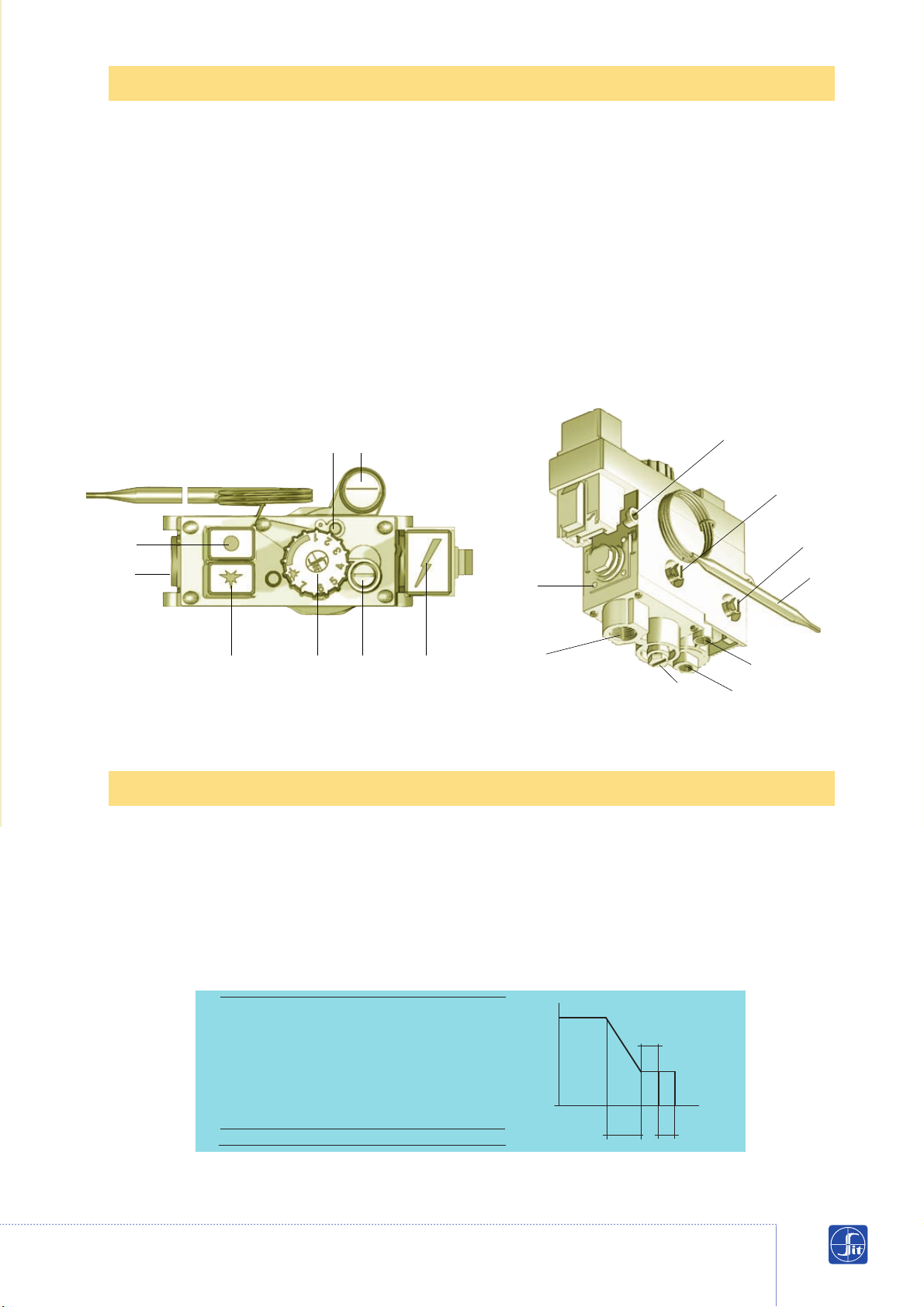
8 Oulet pressure setting screw (versions
with flow regulator)
9 Inlet pressure test point
10 Outlet pressure test point
11 Thermocouple connection
12 Pilot outlet
13 Gas inlet
14 Main gas outlet
15 Flange fixing holes (M5)
16 Fixing points
17 Thermostat bulb
1 Ignition button
2 Shut-down button
3 Piezo-electric ignition button
(optional)
4 Temperature setting knob
5 Screw for adjusting gas flow to pilot
6 Minimum flow setting screw
7 Maximum flow setting screw
(versions with flow regulator)
Thermostat range
a b c
8-33 °C 3 3 2
13-31 °C 2 2 2
13-38 °C 3 3 2
13-48 °C 4 4 3
21-46 °C 3 3 2
30-100 °C 9 9 5
40-72 °C 5 5 3
40-80 °C 5 5 3
100-340 °C 30 30 10
Other ranges are available on request
Data refer EN 126 standard
1
5 8
2
13
4 6 3
15
16
10
9
17
14
12
11
7
(Version with pressure regulator) (Version with flow regulator and bottom gas outlet)
Gas flows
Temperature
▲
b
▲
▼
▲
a
c
Page 4
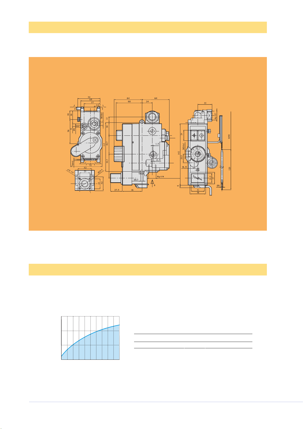
DIMENSIONS
GAS FLOW AS A FUNCTION OF PRESSURE LOSS
0
5
10
Q [m
3
/h d=0.6]
4
2
6
∆p [mbar]
I Family (d = 0.45) Q = 3.9 m3/h ∆p = 5 mbar
II Family (d = 0.6) Q = 3.5 m3/h ∆p = 5 mbar
III Family (d = 1.7) Q = 4.4 kg/h ∆p = 5 mbar
Page 5
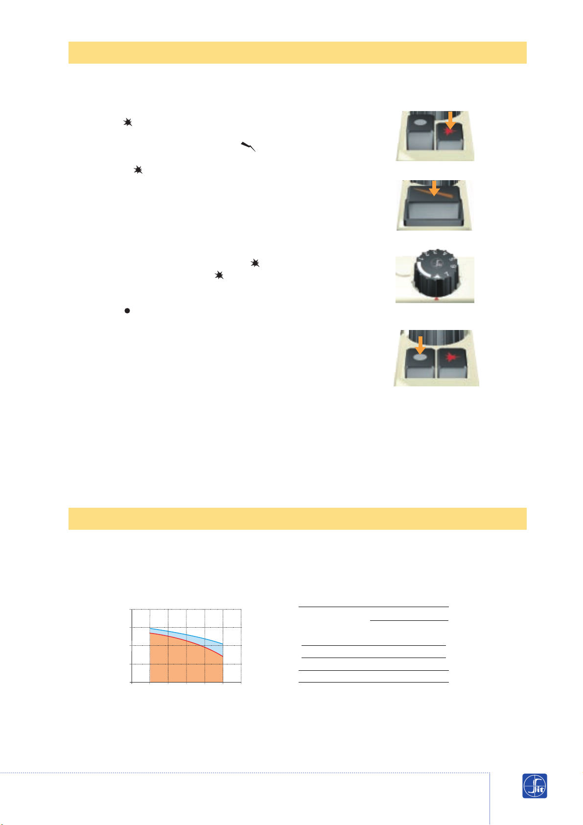
Ignition
Press button and keep it depressed. (Fig. 1)
Light the pilot burner and wait a few seconds. If the valve is fitted
with a piezo-electric igniter, press button to light
the burner. (Fig. 2)
Release button and check that the pilot flame
stays on, otherwise repeat the ignition procedure.
Normal operation
Set knob to the temperature required.
The maximum temperature setting is obtained by turning the
knob fully anti-clockwise. (Fig. 3)
Pilot position (Only in those versions with on the knob)
Turn knob fully clockwise (position )
Shut-down
Press button right down. (Fig.4)
CAUTION: The re-start interlock device prevents the appliance
from re-igniting until the flame supervision device has interrupted
the gas flow. After this stage (i.e. when the magnet unit has
closed) it is possible to re-ignite the appliance.
GAS FLOW SET TO EN 88
Inlet pressure range (mbar)
Type of gas
Nominal Max. Min.
2H 20 25 17
2L 25 30 20
Outlet pressure tolerance +10% -15%
ACTUATION
fig. 1
fig. 2
fig. 3
fig. 4
Q = [m3/h d=0.6]
8
6
4
2
0
6 8 10 12 14 16 18
Pu [mbar]
2L
2H
Page 6
INSTALLATION
Main gas connection
The connection must be made using gas pipes with 1/2 or 3/8 inlet and 3/8 outlet Rp ISO 7.
Torque: 25 Nm. Alternatively, it is possible to use a nut and olive connection for Ø 12 mm
pipes (Codes 0.958.025 and 0.957.007) (torque 15 Nm).
Connection to the pilot burner
Ø 4 mm, Ø 6 mm or Ø 1/4” pipes can be used. Use appropriately sized nut and olive.
Tighten to 7 Nm torque. After making the gas connection, check gas seals and efficiency
of the appliance.
A COLORI
Page 7
SETTINGS AND ADJUSTMENTS
Setting the thermostat
The thermostat is calibrated and sealed at the
factory.
Re-calibration is not authorised as it may
adversely affect the performance of the
appliance to which it is fitted and will also
invalidate warranty.
Low fire adjustment
Turn the MIN screw clockwise to decrease the
flow, anti-clockwise to increase it (calibrated
screws available on request).
Adjusting pilot gas flow
Turn the relevant screw clockwise to decrease
the flow or anticlockwise to increase it.
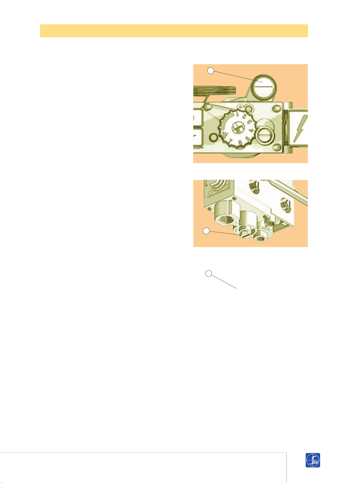
Adjusting the outlet pressure
(Versions with pressure regulator)
Remove the cap and turn the setting screw (A)
clockwise to increase the outlet pressure or
anticlockwise to reduce it.
Adjusting the outlet flow
(Versions with pressure regulator)
Remove the safety cap.
Turn the screw (B) clockwise to decrease the
flow or anticlockwise to increase it.
WARNING
For Minisit operation on third family gases
ensure:
- The MIN screw is replaced by a pre-drilled
version MIN screw as specified by the appliance
manufacturer. This screw must be screwed fully
home.
- The pilot adjusting screw is un-screwed two
turns from the fully closed position.
- Pressure regulator adjustment screw is
screwed fully clockwise or if an output flow
adjuster is fitted, it is screwed fully
anti-clockwise, so that they are non-operable
thereby enabling the gas supply regulator to
be ineffective.
Please ensure you follow all the guidelines detailed in the installation
and operation manual (code 9.956.710) when installing, adjusting or
operating the equipment in your possession.
A
1
B
Adjusting the outlet pressure
Adjusting the outlet flow
Low fire adjustment
IMMAGINE
ITALIANO
Page 8
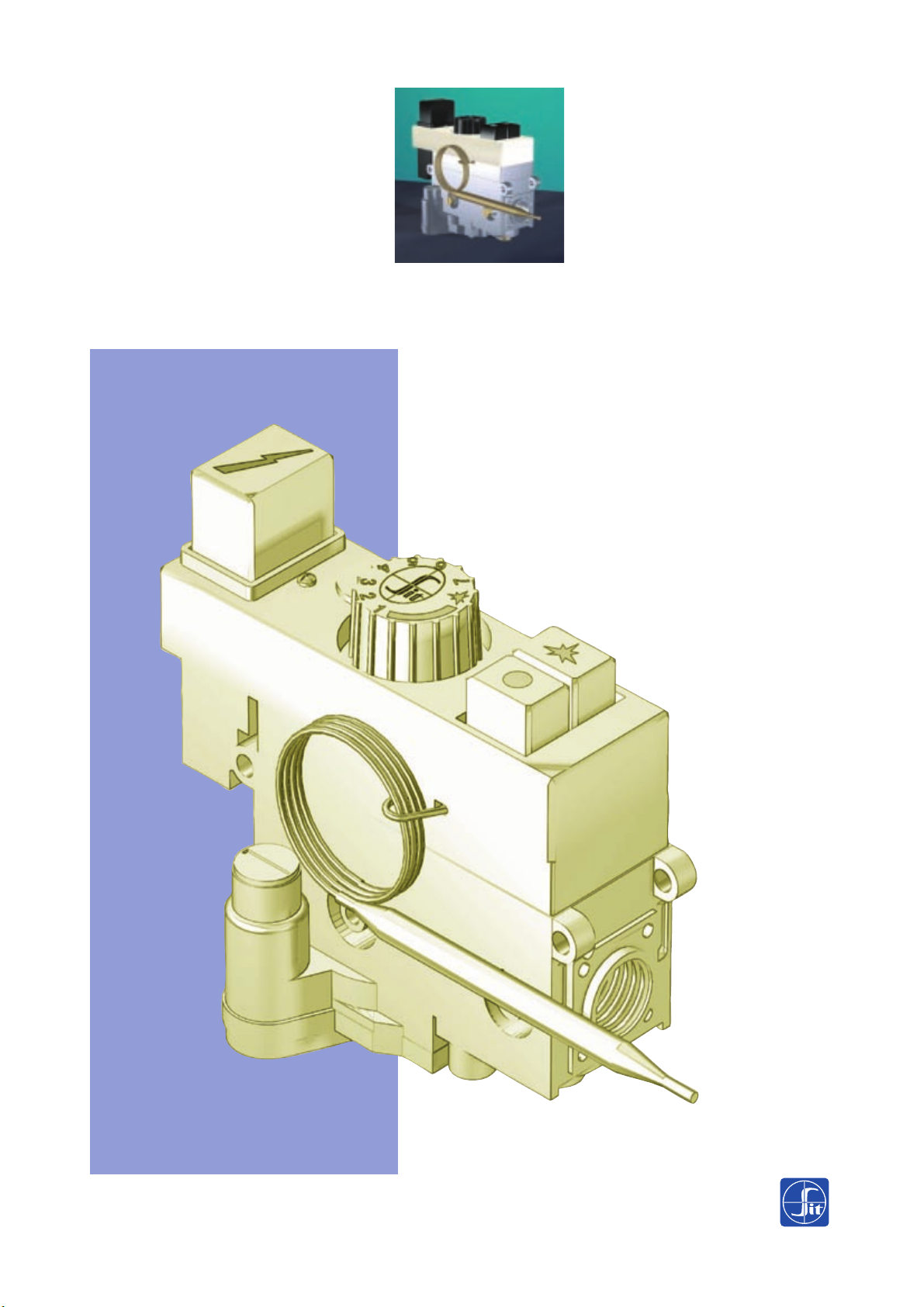
710 MINISIT
Multi-functional control
for gas appliances
without electrical power
supply
SIT La Precisa
Viale dell'Industria 31/33 35129 PADOVA - ITALY
Tel. 049/8293111 - Fax 049/8070093 - Telex 430130 SITEC I
9.955.881 R01 GRAPHIC DESIGN BY START - PD - ITALY
 Loading...