

Page 1
Page 2

SisuDiesel
Fortius Series
Engines
Workshop Manual
03 08
Sisu Diesel Inc.
FIN-37240 Linnavuori, Finland
Telephone: +358 3 341 7111
E-mail: [email protected]
www.sisudiesel.com
Diesel Engines, After Sales
Telefax: +358 3 341 7333
Sisu Diesel Inc. takes no responsibility for any damages caused
because of possible incorrect information in this manual
Page 3

CONTENTS
GENERAL . . . . . . . . . . . . . . . . . . . . . . . . . . . . . . . . . . . . . . . . . . . . . . . . . . . . . . . . . . . . . . . . . . . . . . . . . . . . 6
TO THE USER . . . . . . . . . . . . . . . . . . . . . . . . . . . . . . . . . . . . . . . . . . . . . . . . . . . . . . . . . . . . . . . . . . . . . . . . . 6
SAFETY INSTRUCTIONS . . . . . . . . . . . . . . . . . . . . . . . . . . . . . . . . . . . . . . . . . . . . . . . . . . . . . . . . . . . . . . . . 7
ENGINE TYPE DESIGNATIONS . . . . . . . . . . . . . . . . . . . . . . . . . . . . . . . . . . . . . . . . . . . . . . . . . . . . . . . . . . . 8
LOCATION OF THE ENGINE SERIAL NO. . . . . . . . . . . . . . . . . . . . . . . . . . . . . . . . . . . . . . . . . . . . . . . . . . . 8
MARKING OF THE EEM 2 CONTROL UNIT . . . . . . . . . . . . . . . . . . . . . . . . . . . . . . . . . . . . . . . . . . . . . . . . . 9
LIFTING THE ENGINE . . . . . . . . . . . . . . . . . . . . . . . . . . . . . . . . . . . . . . . . . . . . . . . . . . . . . . . . . . . . . . . . . . 9
CONSTRUCTION . . . . . . . . . . . . . . . . . . . . . . . . . . . . . . . . . . . . . . . . . . . . . . . . . . . . . . . . . . . . . . . . . . . . . 10
Technical data . . . . . . . . . . . . . . . . . . . . . . . . . . . . . . . . . . . . . . . . . . . . . . . . . . . . . . . . . . . . . . . . . . . . . . 10
General . . . . . . . . . . . . . . . . . . . . . . . . . . . . . . . . . . . . . . . . . . . . . . . . . . . . . . . . . . . . . . . . . . . . . . . . . . . 11
Cylinder block . . . . . . . . . . . . . . . . . . . . . . . . . . . . . . . . . . . . . . . . . . . . . . . . . . . . . . . . . . . . . . . . . . . . . . 11
Flywheel housing . . . . . . . . . . . . . . . . . . . . . . . . . . . . . . . . . . . . . . . . . . . . . . . . . . . . . . . . . . . . . . . . . . . 11
Cylinder head . . . . . . . . . . . . . . . . . . . . . . . . . . . . . . . . . . . . . . . . . . . . . . . . . . . . . . . . . . . . . . . . . . . . . . 12
Valve mechanism . . . . . . . . . . . . . . . . . . . . . . . . . . . . . . . . . . . . . . . . . . . . . . . . . . . . . . . . . . . . . . . . . . . 12
Crank mechanism . . . . . . . . . . . . . . . . . . . . . . . . . . . . . . . . . . . . . . . . . . . . . . . . . . . . . . . . . . . . . . . . . . . 12
Timing gears . . . . . . . . . . . . . . . . . . . . . . . . . . . . . . . . . . . . . . . . . . . . . . . . . . . . . . . . . . . . . . . . . . . . . . . 13
Lubricating system . . . . . . . . . . . . . . . . . . . . . . . . . . . . . . . . . . . . . . . . . . . . . . . . . . . . . . . . . . . . . . . . . . 14
Cooling system . . . . . . . . . . . . . . . . . . . . . . . . . . . . . . . . . . . . . . . . . . . . . . . . . . . . . . . . . . . . . . . . . . . . . 15
Inlet and exhaust system . . . . . . . . . . . . . . . . . . . . . . . . . . . . . . . . . . . . . . . . . . . . . . . . . . . . . . . . . . . . . 16
TECHNICAL DATA . . . . . . . . . . . . . . . . . . . . . . . . . . . . . . . . . . . . . . . . . . . . . . . . . . . . . . . . . . . . . . . . . . . . 17
Cylinder block . . . . . . . . . . . . . . . . . . . . . . . . . . . . . . . . . . . . . . . . . . . . . . . . . . . . . . . . . . . . . . . . . . . . . . 17
Cylinder block, 84-engines . . . . . . . . . . . . . . . . . . . . . . . . . . . . . . . . . . . . . . . . . . . . . . . . . . . . . . . . . . . . 17
Cylinder liners . . . . . . . . . . . . . . . . . . . . . . . . . . . . . . . . . . . . . . . . . . . . . . . . . . . . . . . . . . . . . . . . . . . . . . 17
Cylinder head . . . . . . . . . . . . . . . . . . . . . . . . . . . . . . . . . . . . . . . . . . . . . . . . . . . . . . . . . . . . . . . . . . . . . . 17
Valves, rockers and tappets . . . . . . . . . . . . . . . . . . . . . . . . . . . . . . . . . . . . . . . . . . . . . . . . . . . . . . . . . . . 18
Camshaft . . . . . . . . . . . . . . . . . . . . . . . . . . . . . . . . . . . . . . . . . . . . . . . . . . . . . . . . . . . . . . . . . . . . . . . . . . 19
Crankshaft . . . . . . . . . . . . . . . . . . . . . . . . . . . . . . . . . . . . . . . . . . . . . . . . . . . . . . . . . . . . . . . . . . . . . . . . . 19
Crankshaft, 84-engines . . . . . . . . . . . . . . . . . . . . . . . . . . . . . . . . . . . . . . . . . . . . . . . . . . . . . . . . . . . . . . . 20
Flywheel . . . . . . . . . . . . . . . . . . . . . . . . . . . . . . . . . . . . . . . . . . . . . . . . . . . . . . . . . . . . . . . . . . . . . . . . . . 21
Balancing unit, 44-engines . . . . . . . . . . . . . . . . . . . . . . . . . . . . . . . . . . . . . . . . . . . . . . . . . . . . . . . . . . . . 21
Timing gears . . . . . . . . . . . . . . . . . . . . . . . . . . . . . . . . . . . . . . . . . . . . . . . . . . . . . . . . . . . . . . . . . . . . . . . 21
Timing gears, 84-engines . . . . . . . . . . . . . . . . . . . . . . . . . . . . . . . . . . . . . . . . . . . . . . . . . . . . . . . . . . . . . 22
Connecting rod . . . . . . . . . . . . . . . . . . . . . . . . . . . . . . . . . . . . . . . . . . . . . . . . . . . . . . . . . . . . . . . . . . . . . 22
Piston, rings and pin . . . . . . . . . . . . . . . . . . . . . . . . . . . . . . . . . . . . . . . . . . . . . . . . . . . . . . . . . . . . . . . . . 23
Piston, rings and pin, 84-engines . . . . . . . . . . . . . . . . . . . . . . . . . . . . . . . . . . . . . . . . . . . . . . . . . . . . . . . 23
Lubricating system . . . . . . . . . . . . . . . . . . . . . . . . . . . . . . . . . . . . . . . . . . . . . . . . . . . . . . . . . . . . . . . . . . 24
Oil pump, 33- and 44-engines . . . . . . . . . . . . . . . . . . . . . . . . . . . . . . . . . . . . . . . . . . . . . . . . . . . . . . . . . . 24
Oil pump, 66-, 74- and 84-engines . . . . . . . . . . . . . . . . . . . . . . . . . . . . . . . . . . . . . . . . . . . . . . . . . . . . . . 25
Coolant pump, 33- and 44-engines . . . . . . . . . . . . . . . . . . . . . . . . . . . . . . . . . . . . . . . . . . . . . . . . . . . . . . 25
Coolant pump, 66- and 74-engines . . . . . . . . . . . . . . . . . . . . . . . . . . . . . . . . . . . . . . . . . . . . . . . . . . . . . . 25
Coolant pump, 84-engines . . . . . . . . . . . . . . . . . . . . . . . . . . . . . . . . . . . . . . . . . . . . . . . . . . . . . . . . . . . . 25
Thermostat . . . . . . . . . . . . . . . . . . . . . . . . . . . . . . . . . . . . . . . . . . . . . . . . . . . . . . . . . . . . . . . . . . . . . . . . 26
Turbocharger . . . . . . . . . . . . . . . . . . . . . . . . . . . . . . . . . . . . . . . . . . . . . . . . . . . . . . . . . . . . . . . . . . . . . . 26
TIGHTENING TORQUES . . . . . . . . . . . . . . . . . . . . . . . . . . . . . . . . . . . . . . . . . . . . . . . . . . . . . . . . . . . . . . . 27
SPECIAL TOOLS . . . . . . . . . . . . . . . . . . . . . . . . . . . . . . . . . . . . . . . . . . . . . . . . . . . . . . . . . . . . . . . . . . . . . 28
Cylinder block . . . . . . . . . . . . . . . . . . . . . . . . . . . . . . . . . . . . . . . . . . . . . . . . . . . . . . . . . . . . . . . . . . . . . . 28
Timing gear- and flywheel housing . . . . . . . . . . . . . . . . . . . . . . . . . . . . . . . . . . . . . . . . . . . . . . . . . . . . . . 29
Cylinder head and valve mechanism . . . . . . . . . . . . . . . . . . . . . . . . . . . . . . . . . . . . . . . . . . . . . . . . . . . . 30
Crank mechanism . . . . . . . . . . . . . . . . . . . . . . . . . . . . . . . . . . . . . . . . . . . . . . . . . . . . . . . . . . . . . . . . . . . 31
Coolant pump . . . . . . . . . . . . . . . . . . . . . . . . . . . . . . . . . . . . . . . . . . . . . . . . . . . . . . . . . . . . . . . . . . . . . . 32
Fuel system . . . . . . . . . . . . . . . . . . . . . . . . . . . . . . . . . . . . . . . . . . . . . . . . . . . . . . . . . . . . . . . . . . . . . . . . 33
WORK INSTRUCTIONS . . . . . . . . . . . . . . . . . . . . . . . . . . . . . . . . . . . . . . . . . . . . . . . . . . . . . . . . . . . . . . . . 34
1. CYLINDER BLOCK . . . . . . . . . . . . . . . . . . . . . . . . . . . . . . . . . . . . . . . . . . . . . . . . . . . . . . . . . . . . . . . . . . 34
Page 4

A. Measuring cylinder liner wear . . . . . . . . . . . . . . . . . . . . . . . . . . . . . . . . . . . . . . . . . . . . . . . . . . . . . . . . 34
B. Removing cylinder liner . . . . . . . . . . . . . . . . . . . . . . . . . . . . . . . . . . . . . . . . . . . . . . . . . . . . . . . . . . . . 34
C. Checking cylinder block . . . . . . . . . . . . . . . . . . . . . . . . . . . . . . . . . . . . . . . . . . . . . . . . . . . . . . . . . . . . 34
D. Changing camshaft bushing . . . . . . . . . . . . . . . . . . . . . . . . . . . . . . . . . . . . . . . . . . . . . . . . . . . . . . . . . 34
E. Fitting plug at camshaft rear end . . . . . . . . . . . . . . . . . . . . . . . . . . . . . . . . . . . . . . . . . . . . . . . . . . . . . 36
F. Oversize bushings for camshaft . . . . . . . . . . . . . . . . . . . . . . . . . . . . . . . . . . . . . . . . . . . . . . . . . . . . . . 36
G. Fitting plug at camshaft rear end (oversize bushings) . . . . . . . . . . . . . . . . . . . . . . . . . . . . . . . . . . . . . 36
H. Fitting cylinder liner . . . . . . . . . . . . . . . . . . . . . . . . . . . . . . . . . . . . . . . . . . . . . . . . . . . . . . . . . . . . . . . . 37
2. FLYWHEEL HOUSING . . . . . . . . . . . . . . . . . . . . . . . . . . . . . . . . . . . . . . . . . . . . . . . . . . . . . . . . . . . . . . . 40
A. Fitting flywheel housing . . . . . . . . . . . . . . . . . . . . . . . . . . . . . . . . . . . . . . . . . . . . . . . . . . . . . . . . . . . . 40
B. Changing crankshaft rear oil seal . . . . . . . . . . . . . . . . . . . . . . . . . . . . . . . . . . . . . . . . . . . . . . . . . . . . . 40
3. CYLINDER HEAD . . . . . . . . . . . . . . . . . . . . . . . . . . . . . . . . . . . . . . . . . . . . . . . . . . . . . . . . . . . . . . . . . . . 42
A. Removing cylinder head . . . . . . . . . . . . . . . . . . . . . . . . . . . . . . . . . . . . . . . . . . . . . . . . . . . . . . . . . . . . 42
B. Removing valves . . . . . . . . . . . . . . . . . . . . . . . . . . . . . . . . . . . . . . . . . . . . . . . . . . . . . . . . . . . . . . . . . 42
C. Checking cylinder head . . . . . . . . . . . . . . . . . . . . . . . . . . . . . . . . . . . . . . . . . . . . . . . . . . . . . . . . . . . . 42
D. Changing valve guides . . . . . . . . . . . . . . . . . . . . . . . . . . . . . . . . . . . . . . . . . . . . . . . . . . . . . . . . . . . . . 43
E. Machining valve seat . . . . . . . . . . . . . . . . . . . . . . . . . . . . . . . . . . . . . . . . . . . . . . . . . . . . . . . . . . . . . . 43
F. Changing valve seat rings . . . . . . . . . . . . . . . . . . . . . . . . . . . . . . . . . . . . . . . . . . . . . . . . . . . . . . . . . . . 44
G. Grinding valves . . . . . . . . . . . . . . . . . . . . . . . . . . . . . . . . . . . . . . . . . . . . . . . . . . . . . . . . . . . . . . . . . . . 44
H. Fitting valves . . . . . . . . . . . . . . . . . . . . . . . . . . . . . . . . . . . . . . . . . . . . . . . . . . . . . . . . . . . . . . . . . . . . . 44
I. Fitting cylinder head . . . . . . . . . . . . . . . . . . . . . . . . . . . . . . . . . . . . . . . . . . . . . . . . . . . . . . . . . . . . . . . . 45
4. VALVE MECHANISM . . . . . . . . . . . . . . . . . . . . . . . . . . . . . . . . . . . . . . . . . . . . . . . . . . . . . . . . . . . . . . . . 46
A. Reconditioning valve mechanism . . . . . . . . . . . . . . . . . . . . . . . . . . . . . . . . . . . . . . . . . . . . . . . . . . . . . 46
B. Changing camshaft / camshaft gear . . . . . . . . . . . . . . . . . . . . . . . . . . . . . . . . . . . . . . . . . . . . . . . . . . . 46
C. Adjusting valves . . . . . . . . . . . . . . . . . . . . . . . . . . . . . . . . . . . . . . . . . . . . . . . . . . . . . . . . . . . . . . . . . . 47
5. CRANKSHAFT . . . . . . . . . . . . . . . . . . . . . . . . . . . . . . . . . . . . . . . . . . . . . . . . . . . . . . . . . . . . . . . . . . . . . 50
A. Removing crankshaft . . . . . . . . . . . . . . . . . . . . . . . . . . . . . . . . . . . . . . . . . . . . . . . . . . . . . . . . . . . . . . 50
B. Checking crankshaft . . . . . . . . . . . . . . . . . . . . . . . . . . . . . . . . . . . . . . . . . . . . . . . . . . . . . . . . . . . . . . . 50
C. Changing crankshaft gears . . . . . . . . . . . . . . . . . . . . . . . . . . . . . . . . . . . . . . . . . . . . . . . . . . . . . . . . . . 50
D. Fitting crankshaft . . . . . . . . . . . . . . . . . . . . . . . . . . . . . . . . . . . . . . . . . . . . . . . . . . . . . . . . . . . . . . . . . 51
E. Crankshaft hub piece . . . . . . . . . . . . . . . . . . . . . . . . . . . . . . . . . . . . . . . . . . . . . . . . . . . . . . . . . . . . . . 52
F. Checking element of the rubber damper . . . . . . . . . . . . . . . . . . . . . . . . . . . . . . . . . . . . . . . . . . . . . . . . 52
G. Viscose type vibration damper . . . . . . . . . . . . . . . . . . . . . . . . . . . . . . . . . . . . . . . . . . . . . . . . . . . . . . . 52
H. Changing crankshaft pulley / vibration damper . . . . . . . . . . . . . . . . . . . . . . . . . . . . . . . . . . . . . . . . . . 53
6. CONNECTING RODS AND PISTONS . . . . . . . . . . . . . . . . . . . . . . . . . . . . . . . . . . . . . . . . . . . . . . . . . . . 54
A. Removing pistons together with connecting rods . . . . . . . . . . . . . . . . . . . . . . . . . . . . . . . . . . . . . . . . . 54
B. Changing connecting rod bearings . . . . . . . . . . . . . . . . . . . . . . . . . . . . . . . . . . . . . . . . . . . . . . . . . . . . 54
C. Checking connecting rod . . . . . . . . . . . . . . . . . . . . . . . . . . . . . . . . . . . . . . . . . . . . . . . . . . . . . . . . . . . 54
D. Changing piston rings . . . . . . . . . . . . . . . . . . . . . . . . . . . . . . . . . . . . . . . . . . . . . . . . . . . . . . . . . . . . . . 55
E. Checking pistons . . . . . . . . . . . . . . . . . . . . . . . . . . . . . . . . . . . . . . . . . . . . . . . . . . . . . . . . . . . . . . . . . 56
F. Fitting piston pin . . . . . . . . . . . . . . . . . . . . . . . . . . . . . . . . . . . . . . . . . . . . . . . . . . . . . . . . . . . . . . . . . . 56
G. Fitting piston together with connecting rod. . . . . . . . . . . . . . . . . . . . . . . . . . . . . . . . . . . . . . . . . . . . . . 56
7. COUNTERBALANCE (44-engines) . . . . . . . . . . . . . . . . . . . . . . . . . . . . . . . . . . . . . . . . . . . . . . . . . . . . . 58
A. Removing and disassembling counterbalance unit . . . . . . . . . . . . . . . . . . . . . . . . . . . . . . . . . . . . . . .58
B. Reconditioning counterbalance unit . . . . . . . . . . . . . . . . . . . . . . . . . . . . . . . . . . . . . . . . . . . . . . . . . . . 58
C. Fitting counterbalance unit . . . . . . . . . . . . . . . . . . . . . . . . . . . . . . . . . . . . . . . . . . . . . . . . . . . . . . . . . . 58
D. Changing crankshaft gear rim . . . . . . . . . . . . . . . . . . . . . . . . . . . . . . . . . . . . . . . . . . . . . . . . . . . . . . . 59
8. FLYWHEEL . . . . . . . . . . . . . . . . . . . . . . . . . . . . . . . . . . . . . . . . . . . . . . . . . . . . . . . . . . . . . . . . . . . . . . . . 60
A. Changing starter ring gear on flywheel . . . . . . . . . . . . . . . . . . . . . . . . . . . . . . . . . . . . . . . . . . . . . . . . . 60
B. Fitting flywheel . . . . . . . . . . . . . . . . . . . . . . . . . . . . . . . . . . . . . . . . . . . . . . . . . . . . . . . . . . . . . . . . . . . 60
9. TIMING GEAR ASSEMBLY . . . . . . . . . . . . . . . . . . . . . . . . . . . . . . . . . . . . . . . . . . . . . . . . . . . . . . . . . . . 62
A. Removing timing gear casing . . . . . . . . . . . . . . . . . . . . . . . . . . . . . . . . . . . . . . . . . . . . . . . . . . . . . . . . 62
B. Reconditioning idler gear . . . . . . . . . . . . . . . . . . . . . . . . . . . . . . . . . . . . . . . . . . . . . . . . . . . . . . . . . . . 62
Page 5

C. Fitting timing gear casing . . . . . . . . . . . . . . . . . . . . . . . . . . . . . . . . . . . . . . . . . . . . . . . . . . . . . . . . . . . 63
D. Idler gear with bevelled ball bearings . . . . . . . . . . . . . . . . . . . . . . . . . . . . . . . . . . . . . . . . . . . . . . . . . . 64
E. Power take-off . . . . . . . . . . . . . . . . . . . . . . . . . . . . . . . . . . . . . . . . . . . . . . . . . . . . . . . . . . . . . . . . . . . 65
9. TIMING GEAR ASSEMBLY . . . . . . . . . . . . . . . . . . . . . . . . . . . . . . . . . . . . . . . . . . . . . . . . . . . . . . . . . . . 66
A. Removing timing gear casing . . . . . . . . . . . . . . . . . . . . . . . . . . . . . . . . . . . . . . . . . . . . . . . . . . . . . . . . 66
B. Fitting timing gear casing . . . . . . . . . . . . . . . . . . . . . . . . . . . . . . . . . . . . . . . . . . . . . . . . . . . . . . . . . . . 66
C. Fan drive device . . . . . . . . . . . . . . . . . . . . . . . . . . . . . . . . . . . . . . . . . . . . . . . . . . . . . . . . . . . . . . . . . . 68
10. LUBRICATION SYSTEM . . . . . . . . . . . . . . . . . . . . . . . . . . . . . . . . . . . . . . . . . . . . . . . . . . . . . . . . . . . . . 70
A. Oil pressure regulating valve . . . . . . . . . . . . . . . . . . . . . . . . . . . . . . . . . . . . . . . . . . . . . . . . . . . . . . . . 70
B. Removing and dismantling lubricating oil pump . . . . . . . . . . . . . . . . . . . . . . . . . . . . . . . . . . . . . . . . . . 70
C. Assembling and fitting lubricating oil pump . . . . . . . . . . . . . . . . . . . . . . . . . . . . . . . . . . . . . . . . . . . . . 70
D. Piston cooling nozzles . . . . . . . . . . . . . . . . . . . . . . . . . . . . . . . . . . . . . . . . . . . . . . . . . . . . . . . . . . . . . 71
E. Fitting oil sump gasket . . . . . . . . . . . . . . . . . . . . . . . . . . . . . . . . . . . . . . . . . . . . . . . . . . . . . . . . . . . . . 71
F. Lubricating oil cooler . . . . . . . . . . . . . . . . . . . . . . . . . . . . . . . . . . . . . . . . . . . . . . . . . . . . . . . . . . . . . . . 71
G. Lubricating oil quality requirements . . . . . . . . . . . . . . . . . . . . . . . . . . . . . . . . . . . . . . . . . . . . . . . . . . . 73
H. Oil capacities . . . . . . . . . . . . . . . . . . . . . . . . . . . . . . . . . . . . . . . . . . . . . . . . . . . . . . . . . . . . . . . . . . . . 73
11. COOLING SYSTEM . . . . . . . . . . . . . . . . . . . . . . . . . . . . . . . . . . . . . . . . . . . . . . . . . . . . . . . . . . . . . . . . . 74
A. Quality requirements of coolant . . . . . . . . . . . . . . . . . . . . . . . . . . . . . . . . . . . . . . . . . . . . . . . . . . . . . . 74
B. Thermostat . . . . . . . . . . . . . . . . . . . . . . . . . . . . . . . . . . . . . . . . . . . . . . . . . . . . . . . . . . . . . . . . . . . . . . 74
C. Reconditioning coolant pump . . . . . . . . . . . . . . . . . . . . . . . . . . . . . . . . . . . . . . . . . . . . . . . . . . . . . . . . 75
D. Coolant pumps with heavy duty bearings . . . . . . . . . . . . . . . . . . . . . . . . . . . . . . . . . . . . . . . . . . . . . . . 77
E. Reconditioning the coolant pump . . . . . . . . . . . . . . . . . . . . . . . . . . . . . . . . . . . . . . . . . . . . . . . . . . . . . 77
12. INLET AND EXHAUST SYSTEM . . . . . . . . . . . . . . . . . . . . . . . . . . . . . . . . . . . . . . . . . . . . . . . . . . . . . . 78
A. Checking air cleaner . . . . . . . . . . . . . . . . . . . . . . . . . . . . . . . . . . . . . . . . . . . . . . . . . . . . . . . . . . . . . . . 78
B. Checking inlet and exhaust pipes . . . . . . . . . . . . . . . . . . . . . . . . . . . . . . . . . . . . . . . . . . . . . . . . . . . . . 78
C. Checking turbocharger . . . . . . . . . . . . . . . . . . . . . . . . . . . . . . . . . . . . . . . . . . . . . . . . . . . . . . . . . . . . . 78
D. Fitting turbocharger . . . . . . . . . . . . . . . . . . . . . . . . . . . . . . . . . . . . . . . . . . . . . . . . . . . . . . . . . . . . . . . 79
13. FUEL SYSTEM . . . . . . . . . . . . . . . . . . . . . . . . . . . . . . . . . . . . . . . . . . . . . . . . . . . . . . . . . . . . . . . . . . . . 80
Injectors . . . . . . . . . . . . . . . . . . . . . . . . . . . . . . . . . . . . . . . . . . . . . . . . . . . . . . . . . . . . . . . . . . . . . . . . . . 80
A. Removing injectors . . . . . . . . . . . . . . . . . . . . . . . . . . . . . . . . . . . . . . . . . . . . . . . . . . . . . . . . . . . . . . . . 81
B. Inspecting injectors . . . . . . . . . . . . . . . . . . . . . . . . . . . . . . . . . . . . . . . . . . . . . . . . . . . . . . . . . . . . . . . . 81
C. Reconditioning injectors . . . . . . . . . . . . . . . . . . . . . . . . . . . . . . . . . . . . . . . . . . . . . . . . . . . . . . . . . . . . 82
D. Fitting injector in engine . . . . . . . . . . . . . . . . . . . . . . . . . . . . . . . . . . . . . . . . . . . . . . . . . . . . . . . . . . . . 82
E. Fitting delivery pipes . . . . . . . . . . . . . . . . . . . . . . . . . . . . . . . . . . . . . . . . . . . . . . . . . . . . . . . . . . . . . . . 83
Bosch VE rotary pump . . . . . . . . . . . . . . . . . . . . . . . . . . . . . . . . . . . . . . . . . . . . . . . . . . . . . . . . . . . . . . . 84
Technical data . . . . . . . . . . . . . . . . . . . . . . . . . . . . . . . . . . . . . . . . . . . . . . . . . . . . . . . . . . . . . . . . . . . . . . 84
Fuel system, description . . . . . . . . . . . . . . . . . . . . . . . . . . . . . . . . . . . . . . . . . . . . . . . . . . . . . . . . . . . . . . 85
A. Bleeding the fuel system . . . . . . . . . . . . . . . . . . . . . . . . . . . . . . . . . . . . . . . . . . . . . . . . . . . . . . . . . . . 86
B. Measuring the fuel feed pressure . . . . . . . . . . . . . . . . . . . . . . . . . . . . . . . . . . . . . . . . . . . . . . . . . . . . . 86
C. Removing the fuel injection pump . . . . . . . . . . . . . . . . . . . . . . . . . . . . . . . . . . . . . . . . . . . . . . . . . . . . 86
D. Fitting the fuel injection pump . . . . . . . . . . . . . . . . . . . . . . . . . . . . . . . . . . . . . . . . . . . . . . . . . . . . . . . . 86
Bosch VP 30 and VP 44 rotary pump . . . . . . . . . . . . . . . . . . . . . . . . . . . . . . . . . . . . . . . . . . . . . . . . . . . . 88
Technical data . . . . . . . . . . . . . . . . . . . . . . . . . . . . . . . . . . . . . . . . . . . . . . . . . . . . . . . . . . . . . . . . . . . . . . 88
Fuel system, description . . . . . . . . . . . . . . . . . . . . . . . . . . . . . . . . . . . . . . . . . . . . . . . . . . . . . . . . . . . . . . 89
A. Bleeding fuel system . . . . . . . . . . . . . . . . . . . . . . . . . . . . . . . . . . . . . . . . . . . . . . . . . . . . . . . . . . . . . . 90
B. Measuring fuel feed pressure . . . . . . . . . . . . . . . . . . . . . . . . . . . . . . . . . . . . . . . . . . . . . . . . . . . . . . . . 90
C. Removing fuel injection pump . . . . . . . . . . . . . . . . . . . . . . . . . . . . . . . . . . . . . . . . . . . . . . . . . . . . . . . 90
D. Fitting fuel injection pump . . . . . . . . . . . . . . . . . . . . . . . . . . . . . . . . . . . . . . . . . . . . . . . . . . . . . . . . . . . 91
E. Fuel quality requirements . . . . . . . . . . . . . . . . . . . . . . . . . . . . . . . . . . . . . . . . . . . . . . . . . . . . . . . . . . . 93
14. ENGINE CONTROL SYSTEM EEM 2 . . . . . . . . . . . . . . . . . . . . . . . . . . . . . . . . . . . . . . . . . . . . . . . . . . . 94
Construction of the EEM 2 . . . . . . . . . . . . . . . . . . . . . . . . . . . . . . . . . . . . . . . . . . . . . . . . . . . . . . . . . . . . 94
EEM 2 Engine Control System, description . . . . . . . . . . . . . . . . . . . . . . . . . . . . . . . . . . . . . . . . . . . . . . . 95
Service tool of EEM 2 system . . . . . . . . . . . . . . . . . . . . . . . . . . . . . . . . . . . . . . . . . . . . . . . . . . . . . . . . . . 95
A. Changing of Control Unit (ECU) . . . . . . . . . . . . . . . . . . . . . . . . . . . . . . . . . . . . . . . . . . . . . . . . . . . . . . 96
Page 6

B. Sensors of Engine Control System . . . . . . . . . . . . . . . . . . . . . . . . . . . . . . . . . . . . . . . . . . . . . . . . . . . . 97
15. ELECTRICAL SYSTEM . . . . . . . . . . . . . . . . . . . . . . . . . . . . . . . . . . . . . . . . . . . . . . . . . . . . . . . . . . . . . . 98
A. Alternators . . . . . . . . . . . . . . . . . . . . . . . . . . . . . . . . . . . . . . . . . . . . . . . . . . . . . . . . . . . . . . . . . . . . . . 98
B. Starters . . . . . . . . . . . . . . . . . . . . . . . . . . . . . . . . . . . . . . . . . . . . . . . . . . . . . . . . . . . . . . . . . . . . . . . . 101
16. OPTIONAL EQUIPMENT . . . . . . . . . . . . . . . . . . . . . . . . . . . . . . . . . . . . . . . . . . . . . . . . . . . . . . . . . . . 102
A. Compressor (Bendix) . . . . . . . . . . . . . . . . . . . . . . . . . . . . . . . . . . . . . . . . . . . . . . . . . . . . . . . . . . . . . 102
B. Compressor (Knorr) . . . . . . . . . . . . . . . . . . . . . . . . . . . . . . . . . . . . . . . . . . . . . . . . . . . . . . . . . . . . . . 103
Page 7
General
GENERAL
TO THE USER
This Workshop Manual is intended to facilitate workshop operations and repair work.
Fortius series engines (types 33, 44, 66, 74 and 84) are mainly the same in construction, so the same repair instructions usually apply to different engine types. The differences between the various engine types which affect repair
work have been mentioned in technical data and repair instructions. All measurements are in millimetres and valid
when the temperature of the parts is +20°C, unless otherwise stated.
Before starting the repair work read the safety instructions in the beginning of this book. Make sure that you have
all necessary tools, parts and accessories at your disposal. The special tools mentioned in the work instructions are
not all essential, but they speed up and facilitate the work and contribute to successful execution of work. An engine
which has undergone repairs must be run in just like a new one.
Should the engine require measures not described in this manual, please consult your local agent or the Service
Department of Sisu Diesel Inc., Linnavuori, Finland. To facilitate consulting, find out the following facts about the
engine before contacting us:
- engine type
- engine number
- application or equipment
- hours operated or kilometres driven.
In this Workshop Manual the regular service procedure is not handled as this is explained in the Fortius series
Instruction Manual.
As Sisu Diesel Inc. is continuously developing the products, all rights are reserved without separate notice to change
the adjustments, accessories and service- and repair procedure.
6 0
Page 8
General
SAFETY INSTRUCTIONS
In the use and service of the engine there is always
the possibility of injury. Before starting the service
read and understand the following safety instructions and remarks!
Do not start a repair work that you do not fully
handle.
Make sure that the place of the repair and the surrounding gives the possibility for safe working.
Always be sure of the cleanness and the good
order of the repairing place.
Do not use faulty or otherwise useless tools.
Remove all finger rings, chains and watch before
starting work.
Use up-todate protection equipment when you
work. For example eye protection as working with
compressed air for cleaning, grinding, hammering
or other work.
Use lifting device for lifting and transporting heavy
(over 20 kg) pieces. make sure of good condition
of lifting hooks and chains. The lifting ears on the
engine must not be applied by side forces when
lifting.
Never work under an engine that is left handling
under a lifting device or lifted up by a jack. Always
use strong supports before starting the work.
Use only genuine SisuDiesel spare parts.
Avoid touching the exhaust manifold, turbocharger and the other hot parts of the engine.
Open the radiator cap with care when the engine
is hot as the cooling system is pressurised. The
cooling liquid and lubrication oil of a hot engine
causes injuries when touching the skin.
Open fire, smoking and sparks should not be
allowed near the fuel system and batteries. (Specially when loading batteries, explosive.)
Always disconnect the minus (-) wire of the battery
when doing service or repair of the electric system.
At temperatures on excess of 300°C, e.g. if the
engine is burnt by a fire, the viton seals of the
engine (e.g. the undermost o-ring of the cylinder
liner) produce very highly corrosive hydrofluoric
acid. Do not touch with bare hands, viton seals
subjected to abnormally high temperatures.
Always use neoprene rubber or heavy duty gloves
and safety glasses when decontaminating. Wash
the seals and the contaminated area with a 10%
calcium hydroxide or other alkali solution. Put all
removed material in sealed plastic bags and
deliver them to the point stated by the Authorities
concerned. Note! Never destroy viton-seals by
burning!
When checking fuel injectors do not let the jet of
high pressure fuel contact your skin. The fuel penetrates the skin causing severe injuries. Contact
your doctor immediately!
The fuel, lubricating oil and coolant cause irritation
in skin contact for long time.
Start the engine only by using the starting switch
in the cabin.
Do not start an engine if the protection covers are
removed. Note! The fan is difficult to see as the
engine is running! Make sure that wide clothes or
long hear is not caught in the rotating parts of the
engine.
If you start the engine indoors, be sure you have
proper ventilation.
Never use aerosol type of starting aid! (Risk for
explosion.)
When you are operating the engine or working
near it, use hearing protectors to avoid noise injuries.
Stop the engine always before service- or repair
work.
0 7
Avoid unnecessary idling of the engine.
Do not let oil and other liquids drop into the soil
when servicing the engine.
All the gaskets of the engine are of non-asbestos
material.
Be careful when washing the engine with a high
pressure washing machine. Do not use high pressure to wash e.g. the electric and fuel equipment
or the radiator because they can easily be damaged.
Page 9
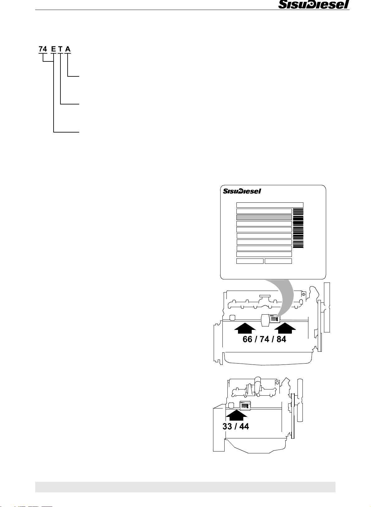
ENGINE TYPE DESIGNATIONS
Equipped with intercooler
A
= air-to-air
I
= air-to-water
Turbocharged engine
W
= by-pass turbo
T = standard turbo
Basic type
74 = cylinder displacement, decilitres
E
= electronic engine management
D = mechanical injection pump
General
LOCATION OF THE ENGINE SERIAL NO.
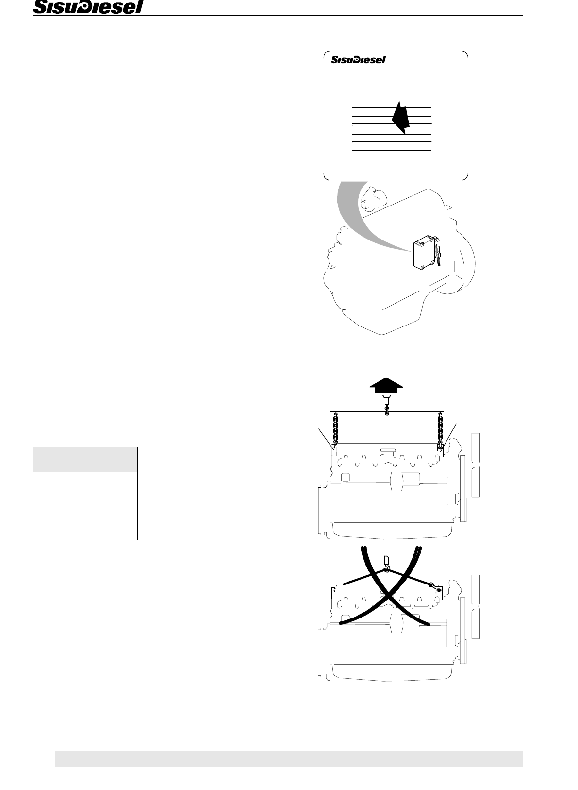
The engine serial number is always stamped on the cylinder block as the picture shows.
The serial number is also markes on the type plate.
Type
SISUDIESEL 74.234 ETA
Power
135 kW 2200 rpm
Serial nr
M07575
Valve
0,35 mm
clearance
Timing
23 degrees
TDC
Low idle
650 rpm
Cust.
N 5853420
Part nr
EU
D20AEE
Family
EPA
YSIDL07.4C2A
Family
Displace ment: 7.4 l
Assembled by:
M07575
Manufacturer
SISU Diesel Inc .
FIN-372 40 Linnavuor i
FINLAND
Fuel: 2-D fuel oil
e17*97/68EA*97/68EA*0016*00
This engine conforms to199 U.S EPA
regul ations l arge nonro ad compress ion
ignition engines
M07576
8 0
Page 10
General
MARKING OF THE EEM 2 CONTROL UNIT
The specification of the application is indicated on the
type plate of the EEM 2 control unit. This specification
must always be stated when ordering a control unit or
asking for adjusting settings.
Note! The engine meets EU97/68/EC Stage 2 and EPA
40 CFR 89 Tier 2 emission requirements.
Do not fit any components on the engine other than those originally suited for it. The use of other than original
SisuDiesel spare parts invalidates the responsibility of
Sisu Diesel Inc. on the fulfilment of the emission requirements.
Manufacturer
SISU Diesel Inc.
FIN-37240 Linnavuori
FINLAND
EEM 2
Engine Control Unit
Hw. ver.
Partno
836864630
Cust.
Part no
Engine
Serial nr
M07575
Type
74 ETA
LIFTING THE ENGINE
Safe lifting of the engine is done with a lifting device
where the lifting force effects the lifting ears vertically.
Weight of engine
Engine
type
33 280
44 340
66 510
74 520
84 660
*) Dry weight without flywheel and electrics
A = Engine lifting ears
Weight
kg *)
A
A
0 9
Page 11
General
CONSTRUCTION
Technical data
Engine type 33 44 66 74 84
Principal dimensions and data
Number of cylinders 34666
Displacement (ltr) 3,3 4,4 6,6 7,4 8,4
Cylinder bore (mm) 108 108 108 108 111
Stroke (mm) 120 120 120 134 145
Combustion Direct injection
Injection timing (installation mark) Marked on the crankshaft pulley/damper
Valve clearance, intake and exhaust (mm) 0,35 (cold or hot)
Direction of rotation from the engine front Clockwise
Fuel system
Injection pump
Stanadyne DB4
Bosch VP 30
Bosch VP 44
Bosch P 7100
Fuel The fuel must be according to norm EN 590,
see page 93
Injection order 1-2-3 1-2-4-3 1-5-3-6-2-4
Feed pressure at idle speed 1,0...1,2 bar
Injector Five-hole nozzle
Opening pressure of the nozzle 270 bar
Adjusting pressure of the nozzle 278 bar
Fuel filters
Pre-filter Stanadyne 30 µ
Final filter Stanadyne 5 µ
Lubrication system
Oil pressure in hot engine at running speed 2,5...5,0 bar
Oil pressure at idle speed, min 1,0 bar
Oil capacity see page 73
Oil quality requirements see page 73
Cooling system
Number of thermostats 1 1 1/2 2 2
Opening temperature ∅ 54 mm = 79°C ∅ 67 mm = 83°C
Coolant quality requirements see page 74
10 0
Page 12
General
General
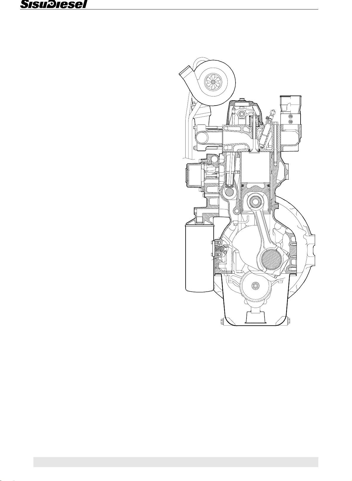
The Fortius engine series consists of water-cooled inline diesel engines with three, four and six cylinders.
The turbocharged engines are equipped with wet, changeable cylinder liners.
The all engine types have a rigid and ribbed cylinder
block. The crank mechanism is designed for supercharging. The cylinder liners are wet and supported at the
middle. The cylinder head bolts are high tensile bolts.
Cylinder block
The cylinder block is the main body of the engine, to
which other engine parts are attached. Wet and replaceable cylinder liners are supported at the middle which
reduces vibrations and directs coolant circulation mainly to the upper part of the liners.
The seal between the cylinder liner lower part and the
cylinder block is achieved by three o-rings, which are
fitted in grooves in the liner. The upper part is sealed by
the cylinder head gasket.
The camshaft is located in the cylinder block. The
camshaft front bearing location is fitted with a separate
bearing sleeve. The remaining bearing locations are
machined directly in the cylinder block. The 66-, 74- and
84-engines have separate bearing sleeves in all camshaft bearing locations. The drilling for the camshaft rear
end is covered with a plug.
There are spaces on both sides of the rear main bearing
for guide bearing shims (the crankshaft thrust bearings).
Flywheel housing
The flywheel housing is fitted at the rear end of the cylinder block. The seal for the crankshaft rear end is placed in a bore in the housing. The starter motor fixing
point is fitted in the flywheel housing.
The lower face of the flywheel housing functions as a
sealing surface for the oil sump gasket. This means that
the lower face of the cylinder block must be level with
the flywheel housing. When fitting the flywheel housing,
its position is determined by tension pins.
The flywheel housing are delivered according to the requirements set, by the engine application and different
flywheel housings can be mounted on all engine types.
0 11
Page 13
General
Cylinder head
Crank mechanism
The crankshaft is forged from chrome alloy special
steel and is induction hardened at the bearing and sealing surfaces. This makes it possible to grind bearings
four times without a new heat treatment. Gear wheels
are located at the front end of the crankshaft. They are
a press fit, and drive the idler wheel and oil pump. In addition, the front end of the crankshaft has splines for the
hub of the V-belt pulley. An oil deflector ring is fitted between the hub and gear wheel, and a dust shield is fitted
on the hub in order to protect the seal.
The crankshaft is supported on the cylinder block by
main bearings which are placed on both sides of each
cylinder. Thus there is one main bearing more than cylinders. The crankshaft thrust washers are placed in
both sides of the rearmost main bearing.
At the rear end of the crankshaft there is fitted a flywheel
on which is a press-fit a starter ring gear. The forged
connecting rod has an I-section cross-section. The bearing location at the bottom end of the connecting rod is
fracture-split, and the bearing cup is secured by two
special elongated screws. The upper part has a wedgeshaped bearing location, in which the piston pin bearing
bushing is fitted with a press fit.
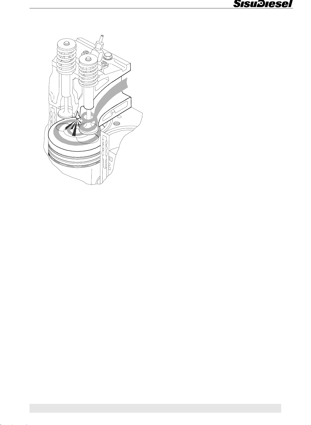
33- and 44-engines have one cylinder head. 66-, 74and 84-engines have two cylinder heads which are
exchangeable with each other and also with the cylinder
head on the 33-engine. Each cylinder has its own inlet
and exhaust ports located on either side of the head.
Between hot exhaust valves a cool inlet valve is fitted to
balance the thermal load.
Cylinder head bolts are high tensile bolts which are tightened up to yield limit using angle tightening principle.
Due to the large stretch the tightening forces are kept
constant during the whole lifetime and retightening is
unnecessary.
The injector locations are machined directly into the cylinder head. The inlet and exhaust valve guides are
identical and can be interchanged. Exhaust valves are
fitted with separate valve seat rings. Also the engines
with high output are equipped with separate inlet valve
seats.
Valve mechanism
The piston is made of an eutectic aluminium alloy. In the
upper face of the piston there is a combustion chamber.
The shape of the chamber is intended to maximise the
mixture of air and fuel. The upper ring location is formed
in a cast iron ring which is cast in the piston. In addition,
the piston is graphite coated to ensure correct runningin.
The piston has three rings. The upper molybdenum-coated ring has a wedge-shaped cross-section. On some
slight supercharged engines the upper ring is right-angled. The middle ring is tapered and it fits into its groove.
The taper taking up the clearance. The oil control ring is
spring loaded and it has a two-stage, chromed scraping
edge.
Some four-cylinder engines (44) are equipped with a
balancer unit. The eccentric weights, which rotate at
twice the engine speed, even out the vibration forces
exerted by the movement of the pistons and the crank
mechanism.
The valve mechanism is operated by the camshaft
which is located in the cylinder block. The drive is transferred with the help of tappets and push rods. The
camshaft gear wheel is fitted with a press fit and fixed
with a key. Each bearing is lubricated by the force feed
lubrication system through drilled oilways in the cylinder
block.
12 0
Page 14
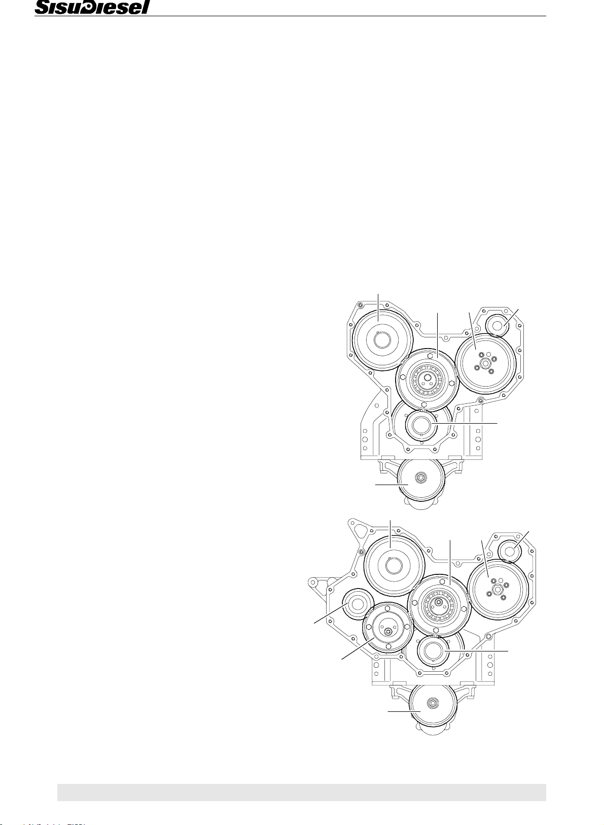
General
Timing gears
33-, 44-, 66- and 74-engines
The timing gear train consists of hardened, helically cut
gear wheels. The gears are encased by the timing gear
casing which is fitted to the front of the engine. The timing gear drives the camshaft, fuel injection pump and
oil pump.
If the engine is equipped with a hydraulic pump, it is driven via a gear or a separate drive unit.
The idler gear is supported with a bearing sleeve / ball
bearing (66- and 74-engines) on the shaft on the front
face of the cylinder block. Two different dimensions of
gear and shaft is used.
84-engines
There are two main types of a timing gear assemblies,
so-called narrow (A) and broad (B) timing gear casing.
The timing gear train consists of hardened, helically cut
gear wheels. The gears are encased by the timing gear
casing which is fitted to the front of the engine. The timing gear drives the camshaft, fuel injection pump, oil
pump and coolant pump.
If the engine is equipped with the broad timing gear casing, there is a separate drive unit for a hydraulic pump
or a compressor. The drive unit is driven via a small idler
gear.
The idler gear is supported with a bevelled ball bearing
on the shaft on the front face of the cylinder block.
Timing gears
1. Camshaft gear
2. Idler gear
3. Injection pump gear
4. Coolant pump gear
5. Crankshaft gears
6. Oil pump gear
7. Small idler gear
8. P.T.O. gear
A
B
8
1
2
3
6
1
23
4
5
4
0 13
5
7
6
Page 15
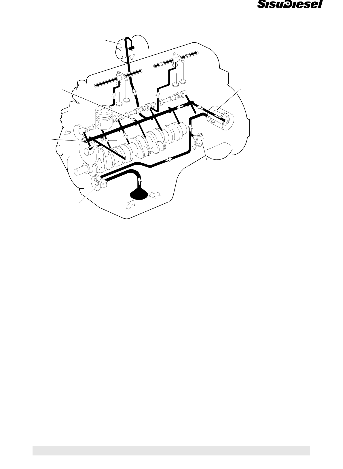
Lubricating system
General
4
7
5
1
6
The engine has a pressure lubricating system in which
the oil pump (gear pump) is attached to the cylinder
block lower face. The oil is sucked up by the pump
through a suction strainer. After the pump the oil is led
through an oilway to the oil pressure regulating valve
via the oil cooler to the oil filter. After the filter, the oil is
led through the main oil gallery from which oilways
branch out. The oil is led through the oilways in the main
bearings and through the crankshaft to the big-end bearings.
The oil is further directed from the main gallery to the
turbocharger and to a possible compressor. In addition,
the camshaft bearing points and the valve mechanism
get their lubrication oil via the main oil gallery.
3
2
Lubricating system (66- and 74-engines)
1. Oil pump
2. Oil pressure regulating valve
3. Oil filter
4. Turbocharger
5. Main oil gallery
6. Piston cooling nozzle
7. Oil pressure sensor
The oil filter is of main flow type. It has a replaceable
cartridge mounted on the left side of the engine, 84-engines on the right side. At the bottom of the oil filter cartridge there is a by-pass valve for cold start or possible
clogging of the filter.
Some engine types are equipped with a oil cooler located between the cylinder block and the oil filter. All oil
that circulates through the filter also goes through the
cooler and is cooled by the engine coolant circulating in
the oil cooler.
The 84-engines are equipped with an plate type oil cooler, that is situated on the right side of the engine above
the filter. The cooler is of main flow type.
The undersides of the pistons of the engines with high
output are always cooled by the oil spray when the oil
pressure is more than 3 bar.
The oil pressure regulating valve is located under the oil
filter on the left side of the engine, 84-engines on the
right side. The regulating valve keeps the oil pressure
constant, independent of the engine speed. At working
speed the oil pressure is 2,5 to 5 bar depending on the
temperature and the quality of lubricating oil. At idling
the pressure is 1,0 bar minimum.
14 0
Page 16
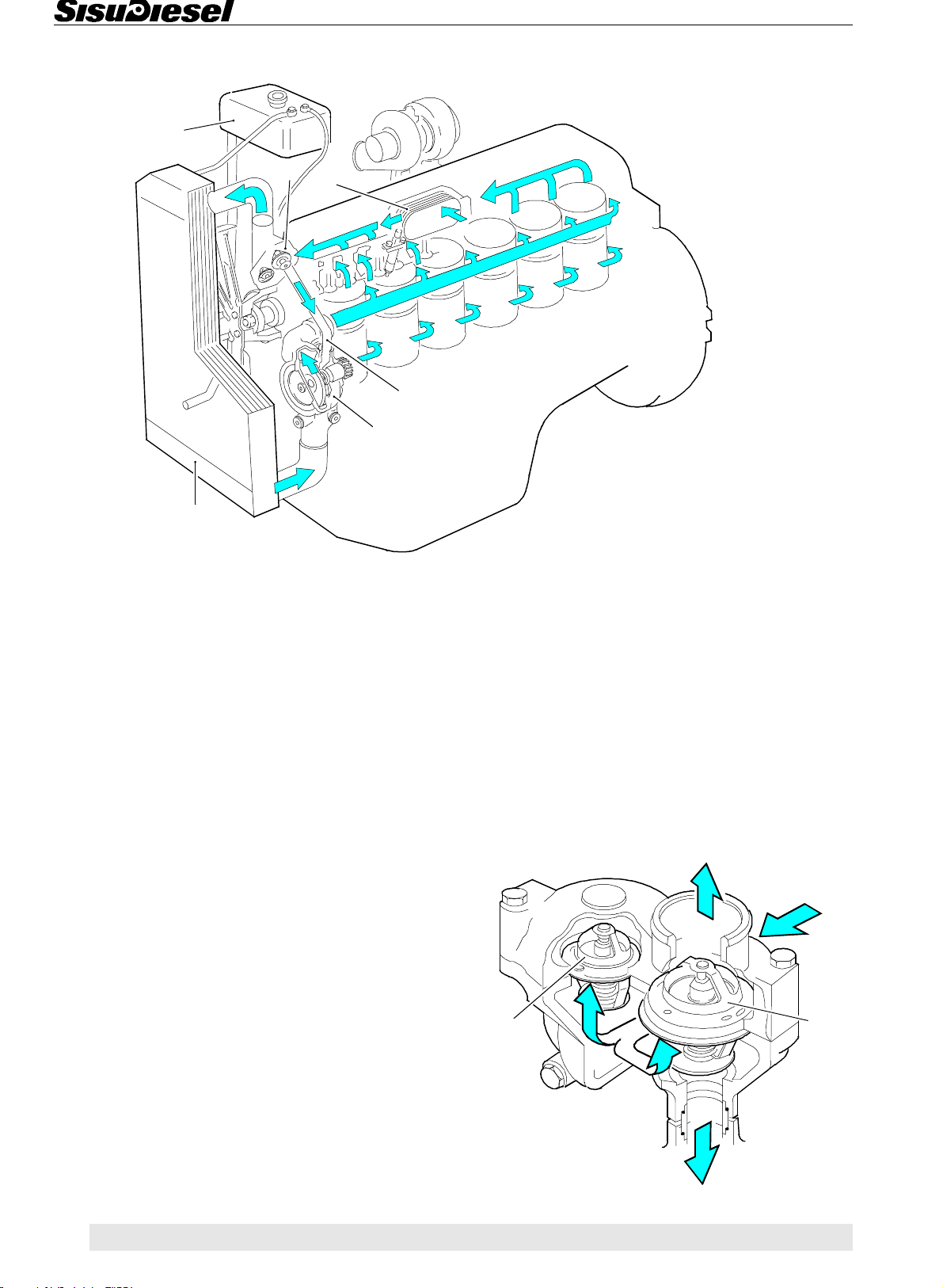
Cooling system
5
General
4
6
3
2
1
Cooling system (84-engine)
1. Radiator
2. Coolant pump
3. By-pass pipe
4. Thermostats
5. Expansion tank
6. Oil cooler
The coolant pump is attached to the front face of the cylinder block and the thermostat housing is mounted
above it.
On 84-engines, the gear driven coolant pump is attached to the front face of the timing gear housing. The
thermostat housing is mounted on front end of the cylinder head.
The system has the internal liquid circulation via the bypass pipe. The circulation is regulated by the 2-way
thermostat. This arrangement ensures a steady warming-up of the engine under all conditions.
In some 66- and 74-engines and 84-engines there are
two separate thermostats where one of them is steering
the by-pass of coolant liquid. The thermostats differ in
types and opening temperatures. When the coolant
temperature is below the thermostat opening temperature the coolant (A) circulates through the by-pass hole
into the coolant pump. The smaller, singleacting thermostat (1) opens first (at 79°C) letting one part of the
coolant (B) into the radiator. Following the load increase, also the other thermostat (2) opens (at 83°C).
This is a double-acting type which closes the by-pass
hole when it opens and directs the coolant (C) into the
radiator. These engine models do not have any separate winter-type thermostats.
C
1
B
2
0 15
A
Page 17
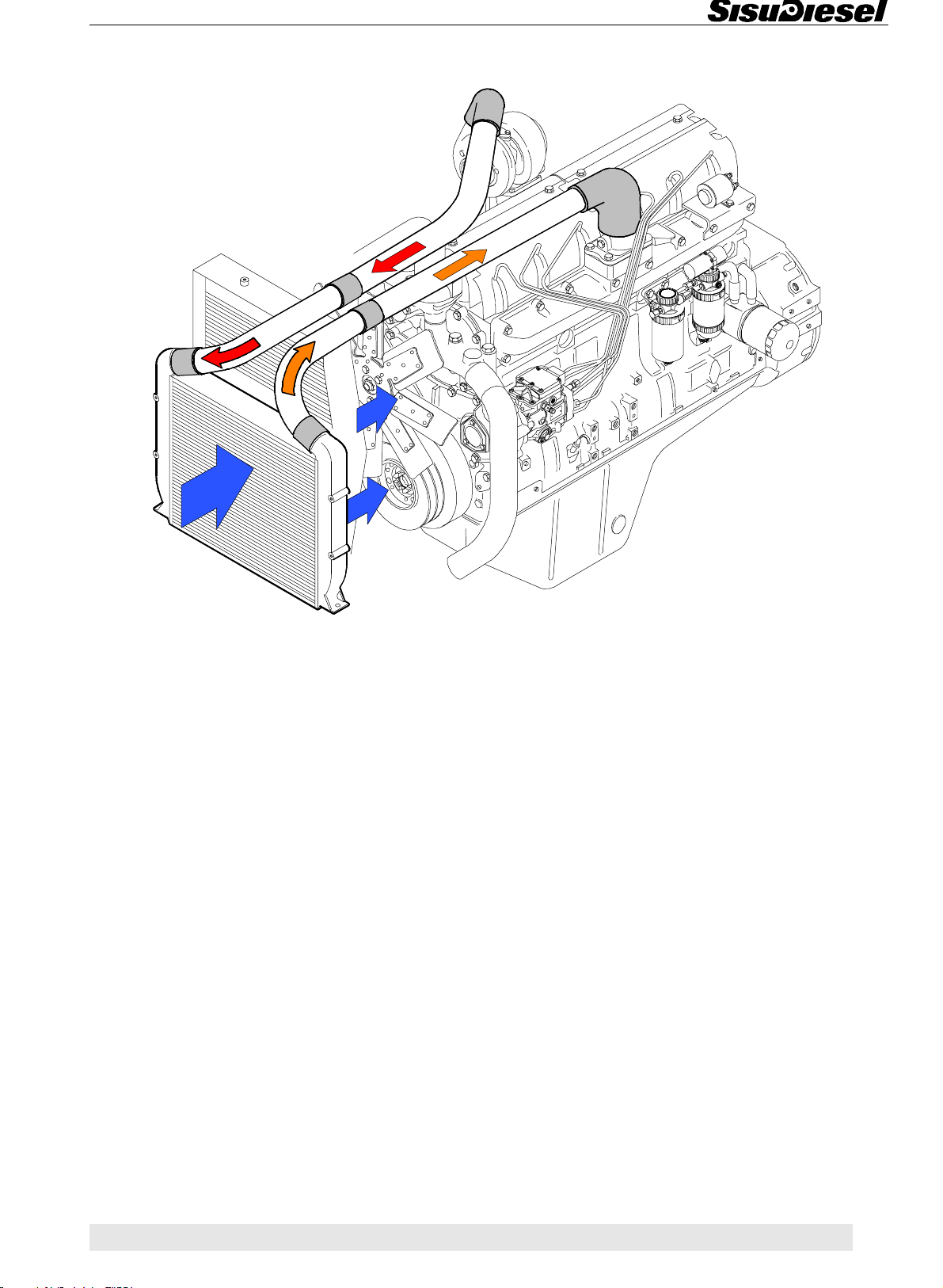
Inlet and exhaust system
General
The filter system for the engine inlet air comprises a
cyclone type pre-cleaner, and a paper filter which acts
as the main filter. The incoming air is made to rotate in
the cyclone pre-cleaner. This causes most of the impurities to settle out and collect in the cyclone pre-cleaner
dust collector. The paper filter comprises one or two
replaceable filter elements. The paper is corrugated
and surrounded by a metal support.
The impurities in the air collect at the larger filter element which can be cleaned when necessary. The inner
safety filter prevents impurities form entering the engine
should the main filter element break, or be fitted incorrectly.
A mechanical or electrical service indicator can be
mounted on the filter housing or on the inlet pipe to
show when the filter cartridge is clogged. The inlet system also includes the hoses between the air cleaner
and the turbocharger and the turbocharger and the intake manifold.
The exhaust manifold is attached to the cylinder head
with high tensile bolts without a separate gasket. Retightening of the manifold bolts is unnecessary.
The turbocharger is a turbo-compressor driven by exhaust gas. The compact design of the turbocharger is
fast to react even during low revolutions. The turbocharger is lubricated and cooled by the lubrication system of
the engine. EWA-engine is equipped with a by-pass turbocharger where excessive air pressure is adjusted by
a so-called by-pass channel. The boost pressure is adjusted correctly by the manufacturer, and must not be
changed afterwards.
The compressed air is cooled on the air-to-air basis.
The air coming from the turbocharger has a temperature abt. 150°C which is cooled by the cooling air of the
engine. The intercooler's cell is ideally installed in front
of the radiator or side-by-side with radiator. The cooling
of the compressed air stabilises the combustion, irrespective of the temperature, and minimises the thermal
and mechanical load of the engine thus lowering nitric
oxides (NOx) and particles (PT). Certain engine versions can also be equipped with an air-to-water intercooler. In that case, the engine specification is ETI.
16 0
Page 18
General
TECHNICAL DATA
Cylinder block
Holes for guide pins . . . . . . . . . . . . . . . . . . . . . . . . . . . . . . . . . . . . . . . . . . . . . . . 13,250...13,320 mm
Main bearing housing diameter . . . . . . . . . . . . . . . . . . . . . . . . . . . . . . . . . . . . . . . 91,000...91,025 mm
Main bearing housing diameter (with bearing 8361 40950) . . . . . . . . . . . . . . . . . 92,000...92,025 mm
Cylinder liner location, diameter:
- upper end . . . . . . . . . . . . . . . . . . . . . . . . . . . . . . . . . . . . . . . . . . . . . . . . . . . . . . 124,514...124,554 mm
- lower end . . . . . . . . . . . . . . . . . . . . . . . . . . . . . . . . . . . . . . . . . . . . . . . . . . . . . . 123,000...123,040 mm
Inner diameter of camshaft bushing (fitted). . . . . . . . . . . . . . . . . . . . . . . . . . . . . . 50,010...50,070 mm
Height of cylinder block . . . . . . . . . . . . . . . . . . . . . . . . . . . . . . . . . . . . . . . . . . . . . 428,170...428,430 mm
Cylinder block, 84-engines
Holes for guide pins . . . . . . . . . . . . . . . . . . . . . . . . . . . . . . . . . . . . . . . . . . . . . . . 13,250...13,320 mm
Main bearing housing diameter . . . . . . . . . . . . . . . . . . . . . . . . . . . . . . . . . . . . . . . 96,000...96,025 mm
Cylinder liner location, diameter:
- upper end . . . . . . . . . . . . . . . . . . . . . . . . . . . . . . . . . . . . . . . . . . . . . . . . . . . . . . 125,014...125,054 mm
- lower end . . . . . . . . . . . . . . . . . . . . . . . . . . . . . . . . . . . . . . . . . . . . . . . . . . . . . . 121,000...121,040 mm
Inner diameter of camshaft bushings (fitted) . . . . . . . . . . . . . . . . . . . . . . . . . . . . . 50,010...50,070 mm
Height of cylinder block . . . . . . . . . . . . . . . . . . . . . . . . . . . . . . . . . . . . . . . . . . . . . 468,900...469,100 mm
Cylinder liners
Protrusion of cylinder liner above cylinder block top face . . . . . . . . . . . . . . . . . . . 0,030...0,080 mm
Max. permissible height difference between liners (under same head) . . . . . . . . 0,02 mm
Outer diameter of cylinder liner guide:
- at upper end of liner . . . . . . . . . . . . . . . . . . . . . . . . . . . . . . . . . . . . . . . . . . . . . . 124,475...124,500 mm
- at lower end of liner. . . . . . . . . . . . . . . . . . . . . . . . . . . . . . . . . . . . . . . . . . . . . . . 122,961...122,986 mm
Liner bore . . . . . . . . . . . . . . . . . . . . . . . . . . . . . . . . . . . . . . . . . . . . . . . . . . . . . . . 108,010...108,032 mm
84-engines
Outer diameter of cylinder liner guide:
- at upper end of liner . . . . . . . . . . . . . . . . . . . . . . . . . . . . . . . . . . . . . . . . . . . . . . 124,975...125,000 mm
- at lower end of liner. . . . . . . . . . . . . . . . . . . . . . . . . . . . . . . . . . . . . . . . . . . . . . . 120,966...120,991 mm
Liner bore . . . . . . . . . . . . . . . . . . . . . . . . . . . . . . . . . . . . . . . . . . . . . . . . . . . . . . . 111,000...111,022 mm
Height of cylinder liner flange, std . . . . . . . . . . . . . . . . . . . . . . . . . . . . . . . . . . . . . 9,03...9,05 mm
Height of cylinder liner flange, 1st oversize. . . . . . . . . . . . . . . . . . . . . . . . . . . . . . 9,08...9,10 mm
Height of cylinder liner flange, 2nd oversize . . . . . . . . . . . . . . . . . . . . . . . . . . . . . 9,13...9,15 mm
Height of cylinder liner flange, 3rd oversize . . . . . . . . . . . . . . . . . . . . . . . . . . . . . 9,23...9,25 mm
Outer diameter of cylinder liner flange . . . . . . . . . . . . . . . . . . . . . . . . . . . . . . . . . 131,700...131,800 mm
Cylinder head
Height of cylinder head . . . . . . . . . . . . . . . . . . . . . . . . . . . . . . . . . . . . . . . . . . . . . 104,800...105,000 mm
Height of cylinder head after repair grinding (minimum) . . . . . . . . . . . . . . . . . . . . 104,000 mm
Inside diameter of valve guide (not fitted) . . . . . . . . . . . . . . . . . . . . . . . . . . . . . . . 9,000...9,015 mm
Outside diameter of valve guide . . . . . . . . . . . . . . . . . . . . . . . . . . . . . . . . . . . . . . 16,028...16,039 mm
Diameter of valve guide bore in cylinder head . . . . . . . . . . . . . . . . . . . . . . . . . . . 16,000...16,018 mm
Position of valve guide top above cylinder head surface . . . . . . . . . . . . . . . . . . . 21 mm
0 17
Page 19
General
Depth of valve head face below cylinder head surface:
- inlet valve . . . . . . . . . . . . . . . . . . . . . . . . . . . . . . . . . . . . . . . . . . . . . . . . . . . . . . 0,7±0,05 mm (max. 2,20 mm)
- exhaust valve . . . . . . . . . . . . . . . . . . . . . . . . . . . . . . . . . . . . . . . . . . . . . . . . . . . 0,6±0,05 mm (max. 2,20 mm)
Angle of valve seat:
- inlet valve . . . . . . . . . . . . . . . . . . . . . . . . . . . . . . . . . . . . . . . . . . . . . . . . . . . . . . 35°+20'
- exhaust valve . . . . . . . . . . . . . . . . . . . . . . . . . . . . . . . . . . . . . . . . . . . . . . . . . . . 45°+20'
Width of valve seat:
- inlet valve . . . . . . . . . . . . . . . . . . . . . . . . . . . . . . . . . . . . . . . . . . . . . . . . . . . . . . 2,9...3,7 mm
- exhaust valve . . . . . . . . . . . . . . . . . . . . . . . . . . . . . . . . . . . . . . . . . . . . . . . . . . . 1,3...2,3 mm
Diameter of exhaust valve seat ring . . . . . . . . . . . . . . . . . . . . . . . . . . . . . . . . . . . 44,070...44,132 mm
Diameter of exhaust valve seat rings recess . . . . . . . . . . . . . . . . . . . . . . . . . . . . 44,000...44,025 mm
Diameter of exhaust valve seat ring (overhaul part 8366 52269) . . . . . . . . . . . . . 44,270...44,332 mm
Diameter of exhaust valve seal ring recess (overhaul part 8366 52269) . . . . . . . 44,200...44,225 mm
Diameter of inlet valve seat ring . . . . . . . . . . . . . . . . . . . . . . . . . . . . . . . . . . . . . . 48,570...48,632 mm
Diameter of inlet valve seat ring recess . . . . . . . . . . . . . . . . . . . . . . . . . . . . . . . . 48,500...48,525 mm
Diameter of inlet valve seat ring (overhaul part 8368 55347) . . . . . . . . . . . . . . . . 48,770...48,832 mm
Diameter of inlet valve seat ring recess (overhaul part 8368 55347) . . . . . . . . . . 48,700...48,725 mm
Valves, rockers and tappets
With a valve clearance of 1,0 mm:
- inlet valve opens . . . . . . . . . . . . . . . . . . . . . . . . . . . . . . . . . . . . . . . . . . . . . . . . . 0°±2° B.T.D.C
- inlet valve closes. . . . . . . . . . . . . . . . . . . . . . . . . . . . . . . . . . . . . . . . . . . . . . . . . 16°±2° A.B.D.C
- exhaust valve opens . . . . . . . . . . . . . . . . . . . . . . . . . . . . . . . . . . . . . . . . . . . . . . 39°±2° B.B.D.C
- exhaust valve closes. . . . . . . . . . . . . . . . . . . . . . . . . . . . . . . . . . . . . . . . . . . . . . 1°±2° A.T.D.C
Valve clearance cold and hot:
- inlet valve . . . . . . . . . . . . . . . . . . . . . . . . . . . . . . . . . . . . . . . . . . . . . . . . . . . . . . 0,35 mm
- exhaust valve . . . . . . . . . . . . . . . . . . . . . . . . . . . . . . . . . . . . . . . . . . . . . . . . . . . 0,35 mm
Angle of valve seat in cylinder head:
- inlet valve . . . . . . . . . . . . . . . . . . . . . . . . . . . . . . . . . . . . . . . . . . . . . . . . . . . . . . 35°+20'
- exhaust valve . . . . . . . . . . . . . . . . . . . . . . . . . . . . . . . . . . . . . . . . . . . . . . . . . . . 45°+20'
Width of valve seat in cylinder head:
- inlet valve . . . . . . . . . . . . . . . . . . . . . . . . . . . . . . . . . . . . . . . . . . . . . . . . . . . . . . 2,9...3,7 mm
- exhaust valve . . . . . . . . . . . . . . . . . . . . . . . . . . . . . . . . . . . . . . . . . . . . . . . . . . . 1,3...2,3 mm
Angle of valve face:
- inlet valve . . . . . . . . . . . . . . . . . . . . . . . . . . . . . . . . . . . . . . . . . . . . . . . . . . . . . . 35°-20'
- exhaust valve . . . . . . . . . . . . . . . . . . . . . . . . . . . . . . . . . . . . . . . . . . . . . . . . . . . 45°-20'
Outside diameter of valve head:
- inlet valve . . . . . . . . . . . . . . . . . . . . . . . . . . . . . . . . . . . . . . . . . . . . . . . . . . . . . . 48 mm
- exhaust valve . . . . . . . . . . . . . . . . . . . . . . . . . . . . . . . . . . . . . . . . . . . . . . . . . . . 41 mm
Max valve movement:
- inlet valve . . . . . . . . . . . . . . . . . . . . . . . . . . . . . . . . . . . . . . . . . . . . . . . . . . . . . . 10,9 mm
- exhaust valve . . . . . . . . . . . . . . . . . . . . . . . . . . . . . . . . . . . . . . . . . . . . . . . . . . . 12,1 mm
Inlet valve stem diameter . . . . . . . . . . . . . . . . . . . . . . . . . . . . . . . . . . . . . . . . . . . 8,960...8,975 mm
Exhaust valve stem diameter . . . . . . . . . . . . . . . . . . . . . . . . . . . . . . . . . . . . . . . . 8,925...8,940 mm
Inlet valve stem clearance. . . . . . . . . . . . . . . . . . . . . . . . . . . . . . . . . . . . . . . . . . . 0,025...0,055 mm
- Reject limit . . . . . . . . . . . . . . . . . . . . . . . . . . . . . . . . . . . . . . . . . . . . . . . . . . . . . 0,30 mm
Exhaust valve stem clearance . . . . . . . . . . . . . . . . . . . . . . . . . . . . . . . . . . . . . . . 0,060...0,090 mm
- Reject limit . . . . . . . . . . . . . . . . . . . . . . . . . . . . . . . . . . . . . . . . . . . . . . . . . . . . . 0,35 mm
Inside diameter of valve guide before fitting . . . . . . . . . . . . . . . . . . . . . . . . . . . . . 9,000...9,015 mm
Outside diameter of valve guide . . . . . . . . . . . . . . . . . . . . . . . . . . . . . . . . . . . . . . 16,028...16,039 mm
Diameter of valve guide bore in cylinder head . . . . . . . . . . . . . . . . . . . . . . . . . . . 16,000...16,018 mm
Protrusion of valve guide top above cylinder head surface. . . . . . . . . . . . . . . . . . 21 mm
Depth of valve face below cylinder head surface:
- inlet valve . . . . . . . . . . . . . . . . . . . . . . . . . . . . . . . . . . . . . . . . . . . . . . . . . . . . . . 0,7±0,05 mm (max. 2,20 mm)
- exhaust valve . . . . . . . . . . . . . . . . . . . . . . . . . . . . . . . . . . . . . . . . . . . . . . . . . . . 0,6±0,05 mm (max. 2,20 mm)
18 0
Page 20
General
Valve spring free length . . . . . . . . . . . . . . . . . . . . . . . . . . . . . . . . . . . . . . . . . . . . 69,8 mm
Spring pressure when spring compressed to a length of:
- 48,6 mm . . . . . . . . . . . . . . . . . . . . . . . . . . . . . . . . . . . . . . . . . . . . . . . . . . . . . . . 327±17 N
- 37,4 mm . . . . . . . . . . . . . . . . . . . . . . . . . . . . . . . . . . . . . . . . . . . . . . . . . . . . . . . 500±23 N
Rocker arm shaft diameter . . . . . . . . . . . . . . . . . . . . . . . . . . . . . . . . . . . . . . . . . . 22,970...22,990
Diameter of rocker arm bore . . . . . . . . . . . . . . . . . . . . . . . . . . . . . . . . . . . . . . . . . 23,000...23,021
Max. permissible push rod deflection (when free). . . . . . . . . . . . . . . . . . . . . . . . . 0,4 mm
Free length of rocker arm spring . . . . . . . . . . . . . . . . . . . . . . . . . . . . . . . . . . . . . . 80 mm
Spring pressure when spring compressed to a length 58 mm . . . . . . . . . . . . . . . 80...100 N
Outside diameter of tappet . . . . . . . . . . . . . . . . . . . . . . . . . . . . . . . . . . . . . . . . . . 29,939...29,960 mm
Diameter of tappet bore in cylinder block . . . . . . . . . . . . . . . . . . . . . . . . . . . . . . . 30,000...30,043 mm
Camshaft
Diameter of camshaft bearing journal no 1 . . . . . . . . . . . . . . . . . . . . . . . . . . . . . . 49,925...49,950 mm
Diameter of camshaft bearing journals (others that no. 1) . . . . . . . . . . . . . . . . . . 49,885...49,910 mm
Diameter of camshaft bearing journals nos 2, 3 and 4 (66/74/84-engines) . . . . . 49,865...49,890 mm
Inside diameter of camshaft bearing bushes (when fitted in position) . . . . . . . . . 50,010...50,070 mm
Diameter of camshaft bearing bores (others than no. 1). . . . . . . . . . . . . . . . . . . . 50,000...50,025 mm
Camshaft clearance in bearing bush no. 1 . . . . . . . . . . . . . . . . . . . . . . . . . . . . . . 0,060...0,145 mm
Camshaft clearance in bearing bushes (others than no. 1) . . . . . . . . . . . . . . . . . 0,090...0,140 mm
Camshaft clearance in bearing bushes nos 2, 3 and 4 (66/74/84-engines) . . . . . 0,110...0,160 mm
Bearing bush tolerance in block (press fit) . . . . . . . . . . . . . . . . . . . . . . . . . . . . . . 0,025...0,080 mm
Diameter of bearing bush bore in block . . . . . . . . . . . . . . . . . . . . . . . . . . . . . . . . 55,620...55,650 mm
Camshaft end play with 0,5 mm gasket between cylinder block and timing gear
housing and between timing gear housing and front cover. . . . . . . . . . . . . . . . . . 0,5...1,0 mm
Cam height (distance between back of cam and tip of cam):
- inlet valve . . . . . . . . . . . . . . . . . . . . . . . . . . . . . . . . . . . . . . . . . . . . . . . . . . . . . . 41,180...41,430 mm
- exhaust valve . . . . . . . . . . . . . . . . . . . . . . . . . . . . . . . . . . . . . . . . . . . . . . . . . . . 40,080...40,330 mm
Cam lift:
- inlet valve . . . . . . . . . . . . . . . . . . . . . . . . . . . . . . . . . . . . . . . . . . . . . . . . . . . . . . 7,38 mm
- exhaust valve . . . . . . . . . . . . . . . . . . . . . . . . . . . . . . . . . . . . . . . . . . . . . . . . . . . 8,28 mm
Camshaft max. permissible deflection (total indicator reading). . . . . . . . . . . . . . . 0,03 mm
Crankshaft
Crankpin diameter:
- standard . . . . . . . . . . . . . . . . . . . . . . . . . . . . . . . . . . . . . . . . . . . . . . . . . . . . . . . 67,981...68,000 mm
- 1. undersize 0,25 mm . . . . . . . . . . . . . . . . . . . . . . . . . . . . . . . . . . . . . . . . . . . . . 67,731...67,750 mm
- 2. undersize 0,50 mm . . . . . . . . . . . . . . . . . . . . . . . . . . . . . . . . . . . . . . . . . . . . . 67,481...67,500 mm
- 3. undersize 1,00 mm . . . . . . . . . . . . . . . . . . . . . . . . . . . . . . . . . . . . . . . . . . . . . 66,981...67,000 mm
- 4. undersize 1,50 mm . . . . . . . . . . . . . . . . . . . . . . . . . . . . . . . . . . . . . . . . . . . . . 66,481...66,500 mm
Crankpin length . . . . . . . . . . . . . . . . . . . . . . . . . . . . . . . . . . . . . . . . . . . . . . . . . . . 40,000...40,160 mm
Main bearing journal diameter:
- standard . . . . . . . . . . . . . . . . . . . . . . . . . . . . . . . . . . . . . . . . . . . . . . . . . . . . . . . 84,985...85,020 mm
- 1st undersize 0,25 mm . . . . . . . . . . . . . . . . . . . . . . . . . . . . . . . . . . . . . . . . . . . . 84,735...84,770 mm
- 2nd undersize 0,50mm . . . . . . . . . . . . . . . . . . . . . . . . . . . . . . . . . . . . . . . . . . . . 84,485...84,520 mm
- 3rd undersize 1,00 mm . . . . . . . . . . . . . . . . . . . . . . . . . . . . . . . . . . . . . . . . . . . . 83,985...84,020 mm
- 4th undersize 1,50 mm . . . . . . . . . . . . . . . . . . . . . . . . . . . . . . . . . . . . . . . . . . . . 83,485...83,520 mm
Main bearing housing diameter (in cylinder block) . . . . . . . . . . . . . . . . . . . . . . . . 91,000...91,025 mm
0 19
Page 21
General
Main bearing shell thickness:
- standard . . . . . . . . . . . . . . . . . . . . . . . . . . . . . . . . . . . . . . . . . . . . . . . . . . . . . . . 2,955...2,965 mm
- 1st undersize 0,25 mm. . . . . . . . . . . . . . . . . . . . . . . . . . . . . . . . . . . . . . . . . . . . 3,080...3,090 mm
- 2nd undersize 0,50 mm . . . . . . . . . . . . . . . . . . . . . . . . . . . . . . . . . . . . . . . . . . . 3,205...3,215 mm
- 3rd undersize 1,00 mm . . . . . . . . . . . . . . . . . . . . . . . . . . . . . . . . . . . . . . . . . . . . 3,455...3,465 mm
- 4th undersize 1,50 mm . . . . . . . . . . . . . . . . . . . . . . . . . . . . . . . . . . . . . . . . . . . . 3,705...3,715 mm
- bearing 8361 40950 (see instruction 5 B) . . . . . . . . . . . . . . . . . . . . . . . . . . . . . . 3,705...3,715 mm
Main bearing clearance. . . . . . . . . . . . . . . . . . . . . . . . . . . . . . . . . . . . . . . . . . . . . 0,050...0,127 mm
Length of thrust bearing journal (journal nearest to flywheel):
- standard (2 standard thrust plates) . . . . . . . . . . . . . . . . . . . . . . . . . . . . . . . . . . . 45,000...45,080 mm
- 1st oversize (one std and one 0,1 mm overthick thrust plate) . . . . . . . . . . . . . . 45,100...45,180 mm
- 2nd oversize (one std and one 0,2 mm overthick thrust plate) . . . . . . . . . . . . . . 45,200...45,280 mm
- 3rd oversize (one 0,1 mm and one 0,2 mm overthick thrust plate). . . . . . . . . . . 45,300...45,380 mm
- 4th oversize (two 0,2 mm overthick thrust plates). . . . . . . . . . . . . . . . . . . . . . . . 45,400...45,480 mm
Other crankshaft journals may not be ground longer.
Crankshaft end float . . . . . . . . . . . . . . . . . . . . . . . . . . . . . . . . . . . . . . . . . . . . . . . 0,100...0,380 mm
Max. permissible ovality and other deformity of crankpins or journals . . . . . . . . . 0,03 mm
Crankshaft unbalance . . . . . . . . . . . . . . . . . . . . . . . . . . . . . . . . . . . . . . . . . . . . . . 1,0 Ncm max.
Balancing unit ring gear location, diameter (44-engines) . . . . . . . . . . . . . . . . . . . 150,220...150,260 mm
Balancing unit ring gear I.D. (44-engines). . . . . . . . . . . . . . . . . . . . . . . . . . . . . . . 150,000...150,040 mm
Crankshaft, 84-engines
Crankpin diameter:
- standard . . . . . . . . . . . . . . . . . . . . . . . . . . . . . . . . . . . . . . . . . . . . . . . . . . . . . . . 72,981...73,000 mm
- 1. undersize 0,25 mm . . . . . . . . . . . . . . . . . . . . . . . . . . . . . . . . . . . . . . . . . . . . . 72,731...72,750 mm
- 2. undersize 0,50 mm . . . . . . . . . . . . . . . . . . . . . . . . . . . . . . . . . . . . . . . . . . . . . 72,481...72,500 mm
- 3. undersize 1,00 mm . . . . . . . . . . . . . . . . . . . . . . . . . . . . . . . . . . . . . . . . . . . . . 71,981...72,000 mm
- 4. undersize 1,50 mm . . . . . . . . . . . . . . . . . . . . . . . . . . . . . . . . . . . . . . . . . . . . . 71,481...71,500 mm
Crankpin length . . . . . . . . . . . . . . . . . . . . . . . . . . . . . . . . . . . . . . . . . . . . . . . . . . . 40,000...40,160 mm
Main bearing journal diameter:
- standard . . . . . . . . . . . . . . . . . . . . . . . . . . . . . . . . . . . . . . . . . . . . . . . . . . . . . . . 89,985...90,020 mm
- 1st undersize 0,25 mm . . . . . . . . . . . . . . . . . . . . . . . . . . . . . . . . . . . . . . . . . . . . 89,735...89,770 mm
- 2nd undersize 0,50mm . . . . . . . . . . . . . . . . . . . . . . . . . . . . . . . . . . . . . . . . . . . . 89,485...89,520 mm
- 3rd undersize 1,00 mm . . . . . . . . . . . . . . . . . . . . . . . . . . . . . . . . . . . . . . . . . . . . 88,985...89,020 mm
- 4th undersize 1,50 mm . . . . . . . . . . . . . . . . . . . . . . . . . . . . . . . . . . . . . . . . . . . . 88,485...88,520 mm
Main bearing housing diameter (in cylinder block) . . . . . . . . . . . . . . . . . . . . . . . . 96,000...96,025 mm
Main bearing shell thickness:
- standard . . . . . . . . . . . . . . . . . . . . . . . . . . . . . . . . . . . . . . . . . . . . . . . . . . . . . . . 2,955...2,965 mm
- 1st undersize 0,25 mm. . . . . . . . . . . . . . . . . . . . . . . . . . . . . . . . . . . . . . . . . . . . 3,080...3,090 mm
- 2nd undersize 0,50 mm . . . . . . . . . . . . . . . . . . . . . . . . . . . . . . . . . . . . . . . . . . . 3,205...3,215 mm
- 3rd undersize 1,00 mm . . . . . . . . . . . . . . . . . . . . . . . . . . . . . . . . . . . . . . . . . . . . 3,455...3,465 mm
- 4th undersize 1,50 mm . . . . . . . . . . . . . . . . . . . . . . . . . . . . . . . . . . . . . . . . . . . . 3,705...3,715 mm
Main bearing clearance. . . . . . . . . . . . . . . . . . . . . . . . . . . . . . . . . . . . . . . . . . . . . 0,050...0,127 mm
Length of thrust bearing journal (journal nearest to flywheel):
- standard (2 standard thrust plates) . . . . . . . . . . . . . . . . . . . . . . . . . . . . . . . . . . . 45,000...45,080 mm
- 1st oversize (one std and one 0,1 mm overthick thrust plate) . . . . . . . . . . . . . . 45,100...45,180 mm
- 2nd oversize (one std and one 0,2 mm overthick thrust plate) . . . . . . . . . . . . . . 45,200...45,280 mm
- 3rd oversize (one 0,1 mm and one 0,2 mm overthick thrust plate). . . . . . . . . . . 45,300...45,380 mm
- 4th oversize (two 0,2 mm overthick thrust plates). . . . . . . . . . . . . . . . . . . . . . . . 45,400...45,480 mm
20 0
Page 22
General
Other crankshaft journals may not be ground longer.
Corner rounded of crankpins and journals . . . . . . . . . . . . . . . . . . . . . . . . . . . . . . R4+0,5 mm
Crankshaft end float . . . . . . . . . . . . . . . . . . . . . . . . . . . . . . . . . . . . . . . . . . . . . . . 0,100...0,380 mm
Max. permissible ovalness and other deformity of crankpins or journals . . . . . . . 0,03 mm
Crankshaft unbalance . . . . . . . . . . . . . . . . . . . . . . . . . . . . . . . . . . . . . . . . . . . . . . 1,0 Ncm max.
Flywheel
Interference fit between ring gear-flywheel . . . . . . . . . . . . . . . . . . . . . . . . . . . . . . 0,425...0,600 mm
Before fitting the ring gear, heat up to a temperature of . . . . . . . . . . . . . . . . . . . . 150...200°C
Flywheel unbalance . . . . . . . . . . . . . . . . . . . . . . . . . . . . . . . . . . . . . . . . . . . . . . . 1,0 Ncm max.
Max permissible axial wobble of flywheel clutch face, measured at inner edge
of clutch face on diameter 200 . . . . . . . . . . . . . . . . . . . . . . . . . . . . . . . . . . . . . . . 0,06:ø200
Balancing unit, 44-engines
Tooth backlash:
- crankshaft ring gear-balancer weight gear wheel . . . . . . . . . . . . . . . . . . . . . . . . 0,1...0,3 mm
- between the balancer weights gear wheels . . . . . . . . . . . . . . . . . . . . . . . . . . . . 0,05...0,250 mm
Balancing weights end float . . . . . . . . . . . . . . . . . . . . . . . . . . . . . . . . . . . . . . . . . 0,1...0,3 mm
Shaft diameter at bearing surfaces . . . . . . . . . . . . . . . . . . . . . . . . . . . . . . . . . . . . 36,000...36,016 mm
Bearing bushing inner diameter (fitted) . . . . . . . . . . . . . . . . . . . . . . . . . . . . . . . . . 36,050...36,075 mm
Diameter of holes in body for shafts, rear end . . . . . . . . . . . . . . . . . . . . . . . . . . . 36,058...36,083 mm
Diameter of holes in body for shafts, front end . . . . . . . . . . . . . . . . . . . . . . . . . . . 35,958...35,983 mm
Shim thickness, cylinder block-balancer unit . . . . . . . . . . . . . . . . . . . . . . . . . . . . 0,2 mm
Timing gears
Tooth backlash:
Crankshaft-idler gear. . . . . . . . . . . . . . . . . . . . . . . . . . . . . . . . . . . . . . . . . . . . . . . 0,05...0,25 mm
Idler gear-camshaft gear . . . . . . . . . . . . . . . . . . . . . . . . . . . . . . . . . . . . . . . . . . . . 0,05...0,25 mm
Idler gear-fuel injection pump gear . . . . . . . . . . . . . . . . . . . . . . . . . . . . . . . . . . . . 0,05...0,25 mm
Max. permissible side wobble of gears . . . . . . . . . . . . . . . . . . . . . . . . . . . . . . . . . 0,05 mm
Idle gear (slide bearing)
- Idler gear shaft, diameter . . . . . . . . . . . . . . . . . . . . . . . . . . . . . . . . . . . . . . . . . . 54,951...54,970 mm
- Inner diameter of idler gear bushing (fitted) . . . . . . . . . . . . . . . . . . . . . . . . . . . . 55,000...55,030 mm
Idle gear (slide bearing, 50 mm length shaft)
- Idler gear shaft, diameter . . . . . . . . . . . . . . . . . . . . . . . . . . . . . . . . . . . . . . . . . . 55,151...55,170 mm
- Inner diameter of idler gear bushing (fitted) . . . . . . . . . . . . . . . . . . . . . . . . . . . . 55,200...55,230 mm
Inner diameter of Idler gear hole . . . . . . . . . . . . . . . . . . . . . . . . . . . . . . . . . . . . . . 60,000...60,030 mm
Camshaft gear hole diameter . . . . . . . . . . . . . . . . . . . . . . . . . . . . . . . . . . . . . . . . 32,000...32,025 mm
Camshaft end diameter . . . . . . . . . . . . . . . . . . . . . . . . . . . . . . . . . . . . . . . . . . . . . 32,043...32,059 mm
Timing marks:
Timing marks on gears are in alignment when the 1st cylinder piston is at its top dead centre
between compression and power strokes.
On crankshaft gear . . . . . . . . . . . . . . . . . . . . . . . . . . . . . . . . . . . . . . . . . . . . . . . . 2 dots on tooth
On idler gear:
- against crankshaft gear mark . . . . . . . . . . . . . . . . . . . . . . . . . . . . . . . . . . . . . . . 0 on tooth
- against camshaft gear mark . . . . . . . . . . . . . . . . . . . . . . . . . . . . . . . . . . . . . . . . 1 dot on tooth
- against fuel injection pump gear mark . . . . . . . . . . . . . . . . . . . . . . . . . . . . . . . . 1 dot on notch
On camshaft gear . . . . . . . . . . . . . . . . . . . . . . . . . . . . . . . . . . . . . . . . . . . . . . . . . 1 dot on notch
On injection pump gear . . . . . . . . . . . . . . . . . . . . . . . . . . . . . . . . . . . . . . . . . . . . . 1 dot on tooth
0 21
Page 23
General
Timing gears, 84-engines
Tooth backlash:
Crankshaft-idler gear. . . . . . . . . . . . . . . . . . . . . . . . . . . . . . . . . . . . . . . . . . . . . . . 0,05...0,25 mm
Idler gear-camshaft gear . . . . . . . . . . . . . . . . . . . . . . . . . . . . . . . . . . . . . . . . . . . . 0,05...0,25 mm
Idler gear-fuel injection pump gear . . . . . . . . . . . . . . . . . . . . . . . . . . . . . . . . . . . . 0,05...0,25 mm
Max. permissible side wobble of gears . . . . . . . . . . . . . . . . . . . . . . . . . . . . . . . . . 0,05 mm
Idler gear shaft, diameter . . . . . . . . . . . . . . . . . . . . . . . . . . . . . . . . . . . . . . . . . . . 49,995...50,011 mm
Inner diameter of idler gear bearing hole . . . . . . . . . . . . . . . . . . . . . . . . . . . . . . . 89,955...89,990 mm
Camshaft gear hole diameter . . . . . . . . . . . . . . . . . . . . . . . . . . . . . . . . . . . . . . . . 32,000...32,025 mm
Camshaft end diameter. . . . . . . . . . . . . . . . . . . . . . . . . . . . . . . . . . . . . . . . . . . . . 32,043...32,059 mm
Timing marks:
Timing marks on gears are in alignment when the 1st cylinder piston is at its top dead centre
between compression and power strokes.
On crankshaft gear . . . . . . . . . . . . . . . . . . . . . . . . . . . . . . . . . . . . . . . . . . . . . . . . 2 dots on tooth
On idler gear:
- against crankshaft gear mark . . . . . . . . . . . . . . . . . . . . . . . . . . . . . . . . . . . . . . . 1 dot on tooth
- against camshaft gear mark . . . . . . . . . . . . . . . . . . . . . . . . . . . . . . . . . . . . . . . . 1 dot on tooth
- against fuel injection pump gear mark . . . . . . . . . . . . . . . . . . . . . . . . . . . . . . . . 2 dots on notch
On camshaft gear . . . . . . . . . . . . . . . . . . . . . . . . . . . . . . . . . . . . . . . . . . . . . . . . . 1 dot on notch
On injection pump gear . . . . . . . . . . . . . . . . . . . . . . . . . . . . . . . . . . . . . . . . . . . . . 1 dot on notch
Connecting rod
Inside diameter of piston pin bush (with bush pressed into connecting rod). . . . . 40,025...40,040 mm
Outside diameter of piston pin bush . . . . . . . . . . . . . . . . . . . . . . . . . . . . . . . . . . . 44,080...44,120 mm
Outside diameter of piston pin bush (oversize 8353 28326). . . . . . . . . . . . . . . . . 44,580...44,620 mm
Interference fit: connecting rod small end bushing-connecting rod. . . . . . . . . . . . 0,057...0,120 mm
Connecting rod small end bore . . . . . . . . . . . . . . . . . . . . . . . . . . . . . . . . . . . . . . . 44,000...44,025 mm
Connecting rod small end bore (oversize bush) . . . . . . . . . . . . . . . . . . . . . . . . . . 44,500...44,525 mm
Connecting rod big end bore. . . . . . . . . . . . . . . . . . . . . . . . . . . . . . . . . . . . . . . . . 71,730...71,749 mm
84-engines
Inside diameter of piston pin bush (with bush pressed into connecting rod). . . . . 44,025...44,040 mm
Outside diameter of piston pin bush (std) . . . . . . . . . . . . . . . . . . . . . . . . . . . . . . . 48,080...48,120 mm
Outside diameter of piston pin bush (oversize 8363 38606). . . . . . . . . . . . . . . . . 48,580...48,620 mm
Interference fit: connecting rod small end bushing-connecting rod. . . . . . . . . . . . 0,057...0,120 mm
Connecting rod small end bore . . . . . . . . . . . . . . . . . . . . . . . . . . . . . . . . . . . . . . . 48,000...48,025 mm
Connecting rod small end bore (oversize bush) . . . . . . . . . . . . . . . . . . . . . . . . . . 48,500...48,525 mm
Connecting rod big end bore. . . . . . . . . . . . . . . . . . . . . . . . . . . . . . . . . . . . . . . . . 76,730...76,749 mm
Big end bearing shell thickness:
- standard . . . . . . . . . . . . . . . . . . . . . . . . . . . . . . . . . . . . . . . . . . . . . . . . . . . . . . . 1,835...1,842 mm
- 1st undersize 0,25 mm . . . . . . . . . . . . . . . . . . . . . . . . . . . . . . . . . . . . . . . . . . . . 1,960...1,967 mm
- 2nd undersize 0,50 mm . . . . . . . . . . . . . . . . . . . . . . . . . . . . . . . . . . . . . . . . . . . 2,085...2,092 mm
- 3rd undersize 1,00 mm . . . . . . . . . . . . . . . . . . . . . . . . . . . . . . . . . . . . . . . . . . . . 2,335...2,342 mm
- 4th undersize 1,50 mm . . . . . . . . . . . . . . . . . . . . . . . . . . . . . . . . . . . . . . . . . . . . 2,585...2,592 mm
Big-end bearing clearance . . . . . . . . . . . . . . . . . . . . . . . . . . . . . . . . . . . . . . . . . . 0,046...0,098 mm
End float (side clearance) at big-end on crankshaft . . . . . . . . . . . . . . . . . . . . . . . 0,200...0,410 mm
Piston pin bushing location perpendicular to longitudinal axis of connecting
rod to be within . . . . . . . . . . . . . . . . . . . . . . . . . . . . . . . . . . . . . . . . . . . . . . . . . . . 0,15:100
Piston pin bushing location and big-end bearing location to be parallel to within . 0,05:100
Weight marking (letter) at lower end.
Max. permissible weight difference between connecting rods in the same engine20 g
Position of connecting rod; weight marking at valve mechanism side
(away from the combustion chamber in the piston)
22 0
Page 24
General
Piston, rings and pin
Minimum distance between piston and cylinder head (measured with a piece
of lead wire thought the injector location hole) . . . . . . . . . . . . . . . . . . . . . . . . . . . 0,900...1,150 mm
Piston diameter:
- 17 mm from lower edge (33/44/66-engines) . . . . . . . . . . . . . . . . . . . . . . . . . . . . 107,873...107,887 mm
- 19 mm from lower edge (74-engines) . . . . . . . . . . . . . . . . . . . . . . . . . . . . . . . . . 107,883...107,897 mm
Pin bore in piston . . . . . . . . . . . . . . . . . . . . . . . . . . . . . . . . . . . . . . . . . . . . . . . . . 40,003...40,009 mm
Piston pin diameter . . . . . . . . . . . . . . . . . . . . . . . . . . . . . . . . . . . . . . . . . . . . . . . . 39,991...40,000 mm
Width of ring grooves:
- 1st groove (right-angled ring) . . . . . . . . . . . . . . . . . . . . . . . . . . . . . . . . . . . . . . . 2,560...2,580 mm
- 2nd grove . . . . . . . . . . . . . . . . . . . . . . . . . . . . . . . . . . . . . . . . . . . . . . . . . . . . . . 2,520...2,540 mm
- 3rd groove . . . . . . . . . . . . . . . . . . . . . . . . . . . . . . . . . . . . . . . . . . . . . . . . . . . . . . 4,040...4,060 mm
Side clearance of piston rings in their grooves:
- 1st ring (right-angled ring) . . . . . . . . . . . . . . . . . . . . . . . . . . . . . . . . . . . . . . . . . . 0,07...0,102 mm
- 2nd ring . . . . . . . . . . . . . . . . . . . . . . . . . . . . . . . . . . . . . . . . . . . . . . . . . . . . . . . . 0,03...0,062 mm
- 3rd ring . . . . . . . . . . . . . . . . . . . . . . . . . . . . . . . . . . . . . . . . . . . . . . . . . . . . . . . . 0,05...0,082 mm
- reject limit . . . . . . . . . . . . . . . . . . . . . . . . . . . . . . . . . . . . . . . . . . . . . . . . . . . . . . 0,15 mm
Piston ring height (in direction of cylinder):
- 1st ring (right-angled ring) . . . . . . . . . . . . . . . . . . . . . . . . . . . . . . . . . . . . . . . . . . 2,478...2,490 mm
- 2nd ring . . . . . . . . . . . . . . . . . . . . . . . . . . . . . . . . . . . . . . . . . . . . . . . . . . . . . . . . 2,478...2,490 mm
- 3rd ring . . . . . . . . . . . . . . . . . . . . . . . . . . . . . . . . . . . . . . . . . . . . . . . . . . . . . . . . 3,975...3,990 mm
Piston ring gap (with piston fitted in cylinder):
- 1st ring (wedge shaped ring) . . . . . . . . . . . . . . . . . . . . . . . . . . . . . . . . . . . . . . . 0,40...0,55 mm
- 1st ring (right-angled ring) . . . . . . . . . . . . . . . . . . . . . . . . . . . . . . . . . . . . . . . . . . 0,30...0,45 mm
- 2nd ring . . . . . . . . . . . . . . . . . . . . . . . . . . . . . . . . . . . . . . . . . . . . . . . . . . . . . . . . 0,60...0,80 mm
- 3rd ring . . . . . . . . . . . . . . . . . . . . . . . . . . . . . . . . . . . . . . . . . . . . . . . . . . . . . . . . 0,30...0,60
- reject limit 1st and 3rd ring . . . . . . . . . . . . . . . . . . . . . . . . . . . . . . . . . . . . . . . . . 1,0 mm
- reject limit 2nd ring . . . . . . . . . . . . . . . . . . . . . . . . . . . . . . . . . . . . . . . . . . . . . . . 1,5 mm
Max. permissible weight difference between pistons in same engine. . . . . . . . . . 25 g
Piston to be heated up to 100°C before fitting gudgeon pin.
Piston position in cylinder: combustion chamber of piston to face towards injector.
Piston, rings and pin, 84-engines
Minimum distance between piston and cylinder head (measured with a piece
of lead wire thought the injector location hole) . . . . . . . . . . . . . . . . . . . . . . . . . . . 0,900...1,150 mm
Piston diameter:
- 15 mm from lower edge . . . . . . . . . . . . . . . . . . . . . . . . . . . . . . . . . . . . . . . . . . . 110,863...110,877 mm
Pin bore in piston . . . . . . . . . . . . . . . . . . . . . . . . . . . . . . . . . . . . . . . . . . . . . . . . . 44,003...44,009 mm
Piston pin diameter . . . . . . . . . . . . . . . . . . . . . . . . . . . . . . . . . . . . . . . . . . . . . . . . 43,994...44,000 mm
Width of ring grooves:
- 1st groove . . . . . . . . . . . . . . . . . . . . . . . . . . . . . . . . . . . . . . . . . . . . . . . . . . . . . . wedge shaped ring
- 2nd grove . . . . . . . . . . . . . . . . . . . . . . . . . . . . . . . . . . . . . . . . . . . . . . . . . . . . . . 2,520...2,540 mm
- 3rd groove . . . . . . . . . . . . . . . . . . . . . . . . . . . . . . . . . . . . . . . . . . . . . . . . . . . . . . 4,040...4,060 mm
Side clearance of piston rings in their grooves:
- 1st ring . . . . . . . . . . . . . . . . . . . . . . . . . . . . . . . . . . . . . . . . . . . . . . . . . . . . . . . . wedge shaped ring
- 2nd ring . . . . . . . . . . . . . . . . . . . . . . . . . . . . . . . . . . . . . . . . . . . . . . . . . . . . . . . . 0,03...0,062 mm
- 3rd ring . . . . . . . . . . . . . . . . . . . . . . . . . . . . . . . . . . . . . . . . . . . . . . . . . . . . . . . . 0,05...0,082 mm
- reject limit . . . . . . . . . . . . . . . . . . . . . . . . . . . . . . . . . . . . . . . . . . . . . . . . . . . . . . 0,15 mm
0 23
Page 25
General
Piston ring height (in direction of cylinder):
- 1st ring . . . . . . . . . . . . . . . . . . . . . . . . . . . . . . . . . . . . . . . . . . . . . . . . . . . . . . . . wedge shaped ring
- 2nd ring . . . . . . . . . . . . . . . . . . . . . . . . . . . . . . . . . . . . . . . . . . . . . . . . . . . . . . . . 2,478...2,490 mm
- 3rd ring . . . . . . . . . . . . . . . . . . . . . . . . . . . . . . . . . . . . . . . . . . . . . . . . . . . . . . . . 3,975...3,990 mm
Piston ring gap (with piston fitted in cylinder):
- 1st ring (wedge shaped ring) . . . . . . . . . . . . . . . . . . . . . . . . . . . . . . . . . . . . . . . 0,35...0,50 mm
- 2nd ring . . . . . . . . . . . . . . . . . . . . . . . . . . . . . . . . . . . . . . . . . . . . . . . . . . . . . . . . 0,60...0,80 mm
- 3rd ring . . . . . . . . . . . . . . . . . . . . . . . . . . . . . . . . . . . . . . . . . . . . . . . . . . . . . . . . 0,30...0,60
- reject limit 1. and 3. ring . . . . . . . . . . . . . . . . . . . . . . . . . . . . . . . . . . . . . . . . . . . 1,0 mm
- reject limit 2. ring. . . . . . . . . . . . . . . . . . . . . . . . . . . . . . . . . . . . . . . . . . . . . . . . . 1,3 mm
Max. permissible weight difference between pistons in same engine. . . . . . . . . . 25 g
Piston to be heated up to 100°C before fitting gudgeon pin.
Piston position in cylinder: combustion chamber of piston to face towards injector.
Lubricating system
Oil pressure at normal running temperature:
- at idling speed (min.). . . . . . . . . . . . . . . . . . . . . . . . . . . . . . . . . . . . . . . . . . . . . . 1,0 bar
- at running speed . . . . . . . . . . . . . . . . . . . . . . . . . . . . . . . . . . . . . . . . . . . . . . . . . 2,5...5,0 bar
Oil pressure regulating valve (engines w/o oil cooled piston)
Free length of oil pressure valve spring . . . . . . . . . . . . . . . . . . . . . . . . . . . . . . . . 49,5 mm
Assembly length / load of oil pressure valve spring . . . . . . . . . . . . . . . . . . . . . . . 28,5 mm / 76 N
Oil pressure regulating valve (engines with oil cooled piston)
Free length of oil pressure valve spring . . . . . . . . . . . . . . . . . . . . . . . . . . . . . . . . 49,8 mm
Assembly length / load of oil pressure valve spring . . . . . . . . . . . . . . . . . . . . . . . 28,5 mm / 127 N
Oil filter by-pass valve opens at a pressure difference of . . . . . . . . . . . . . . . . . . . 2±0,5 bar
Oil pump, 33- and 44-engines
Backlash between gears when crankshaft lies firmly
against the lower side of main bearings:
- crankshaft gear-lubricating oil pump gear. . . . . . . . . . . . . . . . . . . . . . . . . . . . . . 0,05...0,25 mm
- between the pump gears . . . . . . . . . . . . . . . . . . . . . . . . . . . . . . . . . . . . . . . . . . 0,16...0,26 mm
Diameter of drive shaft at bearings for body and cover . . . . . . . . . . . . . . . . . . . . 17,966...17,984 mm
Diameter of shaft holes on body and cover. . . . . . . . . . . . . . . . . . . . . . . . . . . . . . 18,000...18,018 mm
Diameter of gear wheel hole . . . . . . . . . . . . . . . . . . . . . . . . . . . . . . . . . . . . . . . . . 18,060...18,078 mm
Fixed shaft, diameter. . . . . . . . . . . . . . . . . . . . . . . . . . . . . . . . . . . . . . . . . . . . . . . 18,028...18,039 mm
Protrusion of fixed shaft end below pump body face . . . . . . . . . . . . . . . . . . . . . . 0,5...1,0 mm
Thickness of cover gasket. . . . . . . . . . . . . . . . . . . . . . . . . . . . . . . . . . . . . . . . . . . 0,06...0,08 mm
Outside diameter of gear. . . . . . . . . . . . . . . . . . . . . . . . . . . . . . . . . . . . . . . . . . . . 43,486...43,525 mm
Housing diameter . . . . . . . . . . . . . . . . . . . . . . . . . . . . . . . . . . . . . . . . . . . . . . . . . 43,650...43,750 mm
Thickness of gears . . . . . . . . . . . . . . . . . . . . . . . . . . . . . . . . . . . . . . . . . . . . . . . . 24,000...24,027 mm
End play of gears . . . . . . . . . . . . . . . . . . . . . . . . . . . . . . . . . . . . . . . . . . . . . . . . . 0,03...0,11 mm
Depth of housing . . . . . . . . . . . . . . . . . . . . . . . . . . . . . . . . . . . . . . . . . . . . . . . . . . 24,000...24,043 mm
Number of teeth on drive gear (33/44-engines) . . . . . . . . . . . . . . . . . . . . . . . . . . 55 pcs
Number of teeth on drive gear (44-engines) . . . . . . . . . . . . . . . . . . . . . . . . . . . . . 60 pcs
24 0
Page 26
General
Oil pump, 66-, 74- and 84-engines
Backlash between gears when crankshaft lies firmly
against the lower side of main bearings:
- crankshaft gear-lubricating oil pump gear. . . . . . . . . . . . . . . . . . . . . . . . . . . . . . 0,05...0,25 mm
- between the pump gears . . . . . . . . . . . . . . . . . . . . . . . . . . . . . . . . . . . . . . . . . . 0,16...0,26 mm
Diameter of drive shaft at bearings for body and cover . . . . . . . . . . . . . . . . . . . . 17,966...17,984 mm
Diameter of drive shaft bearing hole on body and cover. . . . . . . . . . . . . . . . . . . . 18,000...18,018 mm
Diameter of fixed shaft at gear wheel . . . . . . . . . . . . . . . . . . . . . . . . . . . . . . . . . . 17,966...17,984 mm
Inner diameter of bearing for gear wheel which rotates on fixed shaft . . . . . . . . . 18,000...18,018 mm
Fixed shaft in pump body, diameter . . . . . . . . . . . . . . . . . . . . . . . . . . . . . . . . . . . 20,035...20,048 mm
Protrusion of fixed shaft end below pump body face . . . . . . . . . . . . . . . . . . . . . . 0,5 mm
Thickness of cover gasket. . . . . . . . . . . . . . . . . . . . . . . . . . . . . . . . . . . . . . . . . . . 0,06...0,08 mm
Outer diameter of gear wheels . . . . . . . . . . . . . . . . . . . . . . . . . . . . . . . . . . . . . . . 55,824...55,870 mm
Housing diameter . . . . . . . . . . . . . . . . . . . . . . . . . . . . . . . . . . . . . . . . . . . . . . . . . 56,000...56,120 mm
Thickness of gears . . . . . . . . . . . . . . . . . . . . . . . . . . . . . . . . . . . . . . . . . . . . . . . . 32,000...32,027 mm
End play of gears . . . . . . . . . . . . . . . . . . . . . . . . . . . . . . . . . . . . . . . . . . . . . . . . . 0,03...0,11 mm
Depth of housing . . . . . . . . . . . . . . . . . . . . . . . . . . . . . . . . . . . . . . . . . . . . . . . . . . 32,000...32,043 mm
Number of teeth on drive gears. . . . . . . . . . . . . . . . . . . . . . . . . . . . . . . . . . . . . . . 46 pcs
Coolant pump, 33- and 44-engines
Outside diameter of bearing . . . . . . . . . . . . . . . . . . . . . . . . . . . . . . . . . . . . . . . . . 52 mm
Diameter of bearing housing . . . . . . . . . . . . . . . . . . . . . . . . . . . . . . . . . . . . . . . . . 51,979...52,009 mm
Shaft diameter at bearing . . . . . . . . . . . . . . . . . . . . . . . . . . . . . . . . . . . . . . . . . . . 20,002...20,015 mm
Shaft diameter at impeller . . . . . . . . . . . . . . . . . . . . . . . . . . . . . . . . . . . . . . . . . . . 15,907...15,920 mm
Impeller hole diameter. . . . . . . . . . . . . . . . . . . . . . . . . . . . . . . . . . . . . . . . . . . . . . 15,876...15,894 mm
Diameter of fan hub. . . . . . . . . . . . . . . . . . . . . . . . . . . . . . . . . . . . . . . . . . . . . . . . 0,3 Ncm max.
Max. permissible eccentricity of fan . . . . . . . . . . . . . . . . . . . . . . . . . . . . . . . . . . . ±0,3 mm
The fan belt tension pushing from the middle, deflection from the line . . . . . . . . . 10...15 mm
Coolant pump, 66- and 74-engines
Outside diameter of bearing . . . . . . . . . . . . . . . . . . . . . . . . . . . . . . . . . . . . . . . . . 52 mm
Inside diameter of bearing housing in pump body . . . . . . . . . . . . . . . . . . . . . . . . 51,979...52,009 mm
Shaft diameter at bearing . . . . . . . . . . . . . . . . . . . . . . . . . . . . . . . . . . . . . . . . . . . 19,980...19,993 mm
Shaft diameter at impeller . . . . . . . . . . . . . . . . . . . . . . . . . . . . . . . . . . . . . . . . . . . 15,907...15,920 mm
Impeller hole diameter. . . . . . . . . . . . . . . . . . . . . . . . . . . . . . . . . . . . . . . . . . . . . . 15,876...15,894 mm
Diameter of the seal recess in the pump body . . . . . . . . . . . . . . . . . . . . . . . . . . . 36,450...36,489 mm
Balancing precision of fan . . . . . . . . . . . . . . . . . . . . . . . . . . . . . . . . . . . . . . . . . . . 0,3 Ncm max.
Belt deflection . . . . . . . . . . . . . . . . . . . . . . . . . . . . . . . . . . . . . . . . . . . . . . . . . . . . 10...15 mm
Pump equipped with reinforced bearing
Outer diameter of the front bearing . . . . . . . . . . . . . . . . . . . . . . . . . . . . . . . . . . . . 95 mm
Bearing up diameter in water pump wheel . . . . . . . . . . . . . . . . . . . . . . . . . . . . . . 95,000...95,035 mm
Outer diameter of bearings position in pump frame . . . . . . . . . . . . . . . . . . . . . . . 59,991...60,009 mm
Coolant pump, 84-engines
Outside diameter of bearing . . . . . . . . . . . . . . . . . . . . . . . . . . . . . . . . . . . . . . . . . 52 mm
Inside diameter of bearing housing in pump body . . . . . . . . . . . . . . . . . . . . . . . . 51,970...52,000 mm
Shaft diameter at bearing . . . . . . . . . . . . . . . . . . . . . . . . . . . . . . . . . . . . . . . . . . . 24,996...25,009 mm
Shaft diameter at impeller . . . . . . . . . . . . . . . . . . . . . . . . . . . . . . . . . . . . . . . . . . . 15,907...15,920 mm
Impeller hole diameter. . . . . . . . . . . . . . . . . . . . . . . . . . . . . . . . . . . . . . . . . . . . . . 15,879...15,890 mm
Diameter of the water seal recess in the pump body . . . . . . . . . . . . . . . . . . . . . . 39,981...40,020 mm
0 25
Page 27
Thermostat
General
Order no. Type Opening
begins at
8366 66334 ø67 mm / 83°C 83°±2°C 95°C 8,0 mm
8366 59685 ø67 mm / 86°C 86°±2°C 99°C 8,0 mm
8360 15156 ø54 mm / 79°C 79°±2°C 94°C 7,5 mm
8363 31590 ø67 mm / 83°C 83°±2°C 95°C 8,0 mm
Fully
open at
Max. stroke
Turboc harg er
Schwitzer
S1AS1BS2AS2B
Axial clearance max. 0,14 mm 0,14 mm 0,14 mm 0,14 mm
Radial clearance (compressor end) max. 0,61 mm 0,51 mm 0,82 mm 0,95 mm
Compressor wheel locknut torque 6,8 Nm 8,1 Nm 10,2 Nm 15,6 Nm
Compressor housing screws torque 13,6 Nm 13,6 Nm 13,6 Nm 13,6 Nm
Turbine housing screws torque 21,0 Nm 21,0 Nm 21,0 Nm
Schwitzer
S100 S200 S300
Axial clearance max. 0,10 mm 0,10 mm 0,12 mm
Radial clearance (compressor end) max. 0,82 mm 0,88 mm 0,88 mm
Compressor wheel locknut torque 6,8 Nm 13,6 Nm 20,3 Nm
Compressor housing screws torque 13,6 Nm 13,6 Nm 13,6 Nm
Turbine housing screws torque 21,0 Nm 21,0 Nm 21,0 Nm
26 0
Page 28
General
TIGHTENING TORQUES
Object Nm
Cylinder head bolts and nuts. . . . . . . . . . . . . . . . . . . . . . . . . . . . . . . . . . . . . . . . . . 80 Nm + 90° + 90°
Cylinder head studs to cylinder block . . . . . . . . . . . . . . . . . . . . . . . . . . . . . . . . . . . . . . . . . . 30
Main bearing screws . . . . . . . . . . . . . . . . . . . . . . . . . . . . . . . . . . . . . . . . . . . . . . . . . . . . . 200
Connecting rod screws . . . . . . . . . . . . . . . . . . . . . . . . . . . . . . . . . . . . . . . . . . . . . . . . . . 40 Nm + 90°
Crankshaft nut, 33/44 . . . . . . . . . . . . . . . . . . . . . . . . . . . . . . . . . . . . . . . . . . . . . . . . . . . . . 600
Crankshaft nut, 66/74/84 . . . . . . . . . . . . . . . . . . . . . . . . . . . . . . . . . . . . . . . . . . . . . . . . . 1000
Crankshaft pulley screws . . . . . . . . . . . . . . . . . . . . . . . . . . . . . . . . . . . . . . . . . . . . . . . . . . . 30
Crankshaft pulley screws, 84 . . . . . . . . . . . . . . . . . . . . . . . . . . . . . . . . . . . . . . . . . . . . . . . . 80
Flywheel screws . . . . . . . . . . . . . . . . . . . . . . . . . . . . . . . . . . . . . . . . . . . . . . . . . . . . . . . . . 150
Flywheel screws, 84 . . . . . . . . . . . . . . . . . . . . . . . . . . . . . . . . . . . . . . . . . . . . . . . . . . . . . . 200
Flywheel housing screws:
- M12 . . . . . . . . . . . . . . . . . . . . . . . . . . . . . . . . . . . . . . . . . . . . . . . . . . . . . . . . . . . . . . . . . 150
- M10 . . . . . . . . . . . . . . . . . . . . . . . . . . . . . . . . . . . . . . . . . . . . . . . . . . . . . . . . . . . . . . . . . . 80
Idler gear screws, 33/44/66:
- M10 . . . . . . . . . . . . . . . . . . . . . . . . . . . . . . . . . . . . . . . . . . . . . . . . . . . . . . . . . . . . . . . . . . 60
- M14 . . . . . . . . . . . . . . . . . . . . . . . . . . . . . . . . . . . . . . . . . . . . . . . . . . . . . . . . . . . . . . . . . 200
Idler gear screws (with ball bearing), 66/74/84:
- M14 . . . . . . . . . . . . . . . . . . . . . . . . . . . . . . . . . . . . . . . . . . . . . . . . . . . . . . . . . . . . . . . . . 180
- M8 . . . . . . . . . . . . . . . . . . . . . . . . . . . . . . . . . . . . . . . . . . . . . . . . . . . . . . . . . . . . . . . . . . . 22
Piston cooling valve . . . . . . . . . . . . . . . . . . . . . . . . . . . . . . . . . . . . . . . . . . . . . . . . . . . . . . . 30
Oil pump retaining screws . . . . . . . . . . . . . . . . . . . . . . . . . . . . . . . . . . . . . . . . . . . . . . . . . . 60
Oil cooler connecting piece . . . . . . . . . . . . . . . . . . . . . . . . . . . . . . . . . . . . . . . . . . . . . . . . . 60
Coolant pump pulley screw, 33/44 . . . . . . . . . . . . . . . . . . . . . . . . . . . . . . . . . . . . . . . . . . . . 80
Coolant pump pulley nut, 66/74 . . . . . . . . . . . . . . . . . . . . . . . . . . . . . . . . . . . . . . . . . . . . . 120
Coolant pump gear nut, 84 . . . . . . . . . . . . . . . . . . . . . . . . . . . . . . . . . . . . . . . . . . . . . . . . . 180
Belt tightener screw . . . . . . . . . . . . . . . . . . . . . . . . . . . . . . . . . . . . . . . . . . . . . . . . . . . . . . . 48
Exhaust manifold screws . . . . . . . . . . . . . . . . . . . . . . . . . . . . . . . . . . . . . . . . . . . . . . . . . . . 50
Injector attaching nuts (on studs) . . . . . . . . . . . . . . . . . . . . . . . . . . . . . . . . . . . . . . . . . . . . . 15
Injector nozzle sleeve . . . . . . . . . . . . . . . . . . . . . . . . . . . . . . . . . . . . . . . . . . . . . . . . . . . . . . 60
Always use the torque values listed in the following tables when specific torque values are not available.
Thread Strength class
8.8 10.9
M8 25 Nm 35 Nm
M10 50 Nm 75 Nm
Use a washer with the aluminium parts.
0 27
Page 29
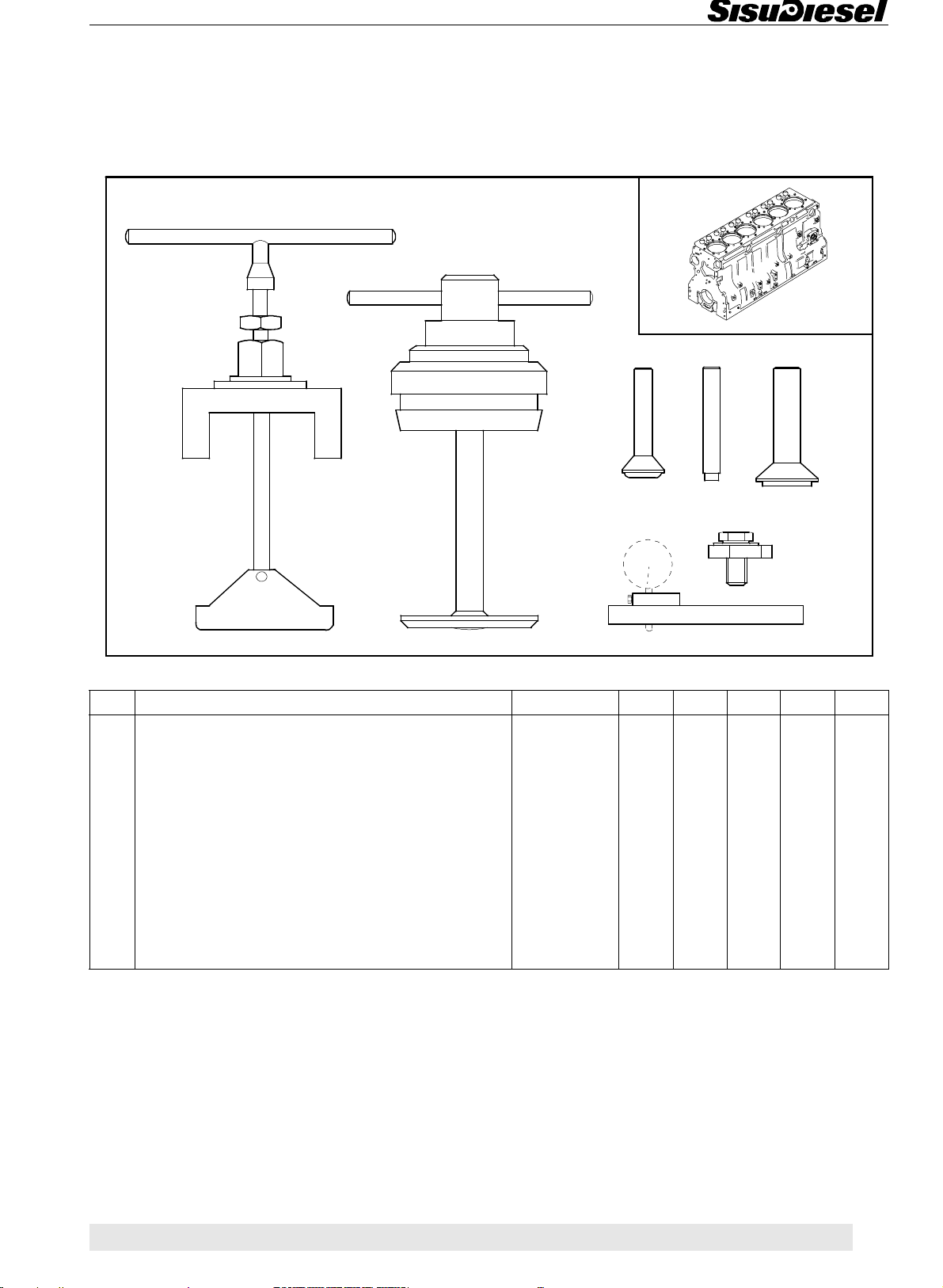
SPECIAL TOOLS
Cylinder block
General
345
12
7
Ref. Description Order no. 33 44 66 74 84
1 Puller for cylinder liner 9051 73100 x x x x
9104 51500 x
2 Milling cutter for cylinder liner seat 9101 65600 x x x x
9104 52000 x
- Spare cutting blade for milling cutter 9045 87600 x x x x x
3 Drift for 40 mm cup plug 9052 46620 x x x x x
4 Drift for 16 mm cup plug 9052 46650 x x x x x
5 Drift for fitting camshaft cup plug 9025 87400 x x x x x
6 Press tool for cylinder liner 9101 66300 x x x x x
7 Holder for dial gauge 9025 79200 x x x x x
6
28 0
Page 30
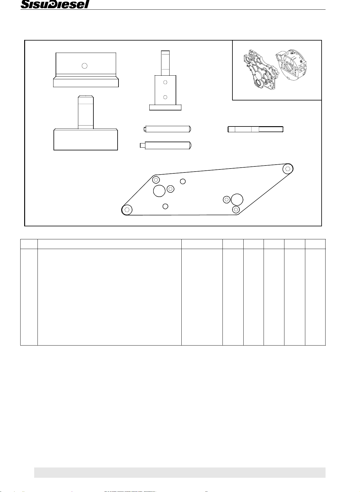
Timing gear- and flywheel housing
1
2
General
3
4
6
5
7
Ref.Description Order no. 3344667484
1 Centring tool for flywheel housing 9052 46400 xxxx
9104 52700 x
2 Drift for fitting rear crankshaft seal 9052 46300 xxxx
9104 52600 x
3 Drift for fitting front crankshaft seal 9030 15200 xxxx
9103 94600 x
4 Drift for tension pins in timing gear housing 9025 98800 xxxx
5 Drift for tension pins in timing gear- and flywheel hou 9025 98700 xxxxx
6 Centring pin for idler gear, narrow timing gear hous. 9104 34600 x
7 Centring tool for idler gear, broad timing gear hous. 9104 05400 x
0 29
Page 31
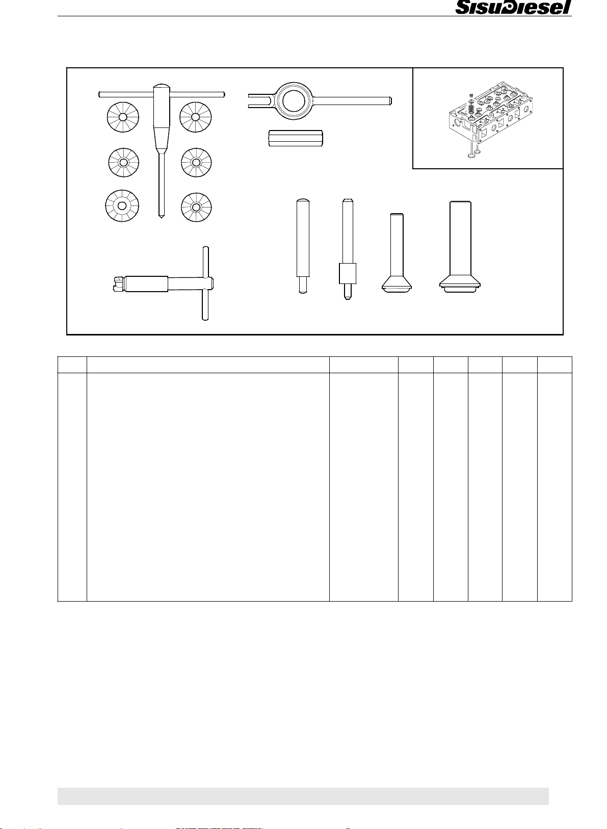
Cylinder head and valve mechanism
1
General
2
3
4
10
5
9
6
7
11 12 13 14
8
Ref. Description Order no. 33 44 66 74 84
1 T-handle for valve seat milling cutter 9101 66100 x x x x x
2 Milling cutter for facing exhaust valve seat 9101 71100 x x x x x
3 Milling cutter for exhaust valve seat 9101 65502 x x x x x
4 Inner milling cutter for exhaust valve seat 9101 65503 x x x x x
5 Milling cutter for facing inlet valve seat 9101 75800 x x x x x
6 Milling cutter for inlet valve seat 9101 65505 x x x x x
7 Inner milling cutter for inlet valve seat 9101 65506 x x x x x
8 Lever for compressing valve spring 9101 66200 x x x x x
9 Counter nut for lever above 9052 47200 x x x x x
10 Milling tool for injector seat 9101 66000 x x x x x
11 Drift for removing valve guide 9101 65800 x x x x x
12 Drift for fitting valve guide 9101 65900 x x x x x
13 Drift for 36 mm cup plug 9052 46660 x x x x x
14 Drift for 45 mm cup plug 9103 94800 x x x
30 0
Page 32
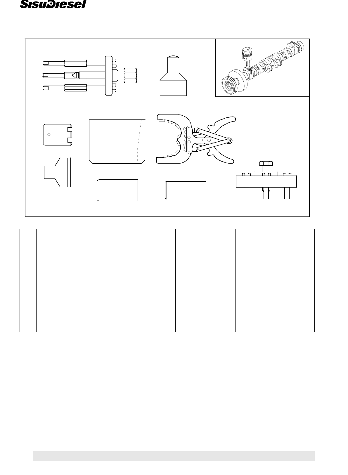
Crank mechanism
General
1
2
5
3
Ref.Description Order no. 3344667484
1 Puller for crankshaft gears 9052 48800 xxxx
2 Spanner for crankshaft nut 9024 55800 x x x
3 Spanner for crankshaft nut 9101 65700 x x x
4 Drift for fitting dust cover 9025 98900 xxxx
5 Conical sleeve for fitting pistons 9020 01100 xxxx
6 Piston ring pliers 9052 46900 xxxxx
7 Drift for fitting crankshaft gears 9103 94700 xxxxx
8 Drift for fitting oil deflector ring, crankshaft front end 9103 94900 x
9 Puller for crankshaft hub 9104 53300 x
4
6
987
9105 18700 x
0 31
Page 33
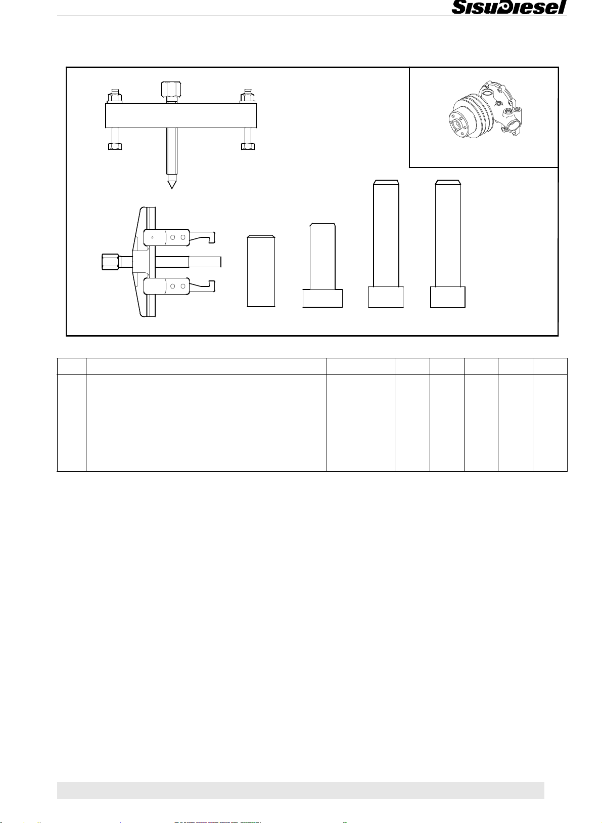
Coolant pump
General
1
2
Ref. Description Order no. 33 44 66 74 84
1 Puller for coolant pump impeller 9101 93200 x x
2 Puller for coolant pump impeller 9104 27700 x x
3 Drift for fitting coolant pump water seal 9051 79300 x x x x
4 Drift for fitting coolant pump bearings 9103 41300 x
5 Drift for fitting coolant pump shaft seal 9103 41000 x
6 Drift for fitting coolant pump water seal 9103 41100 x
6543
32 0
Page 34
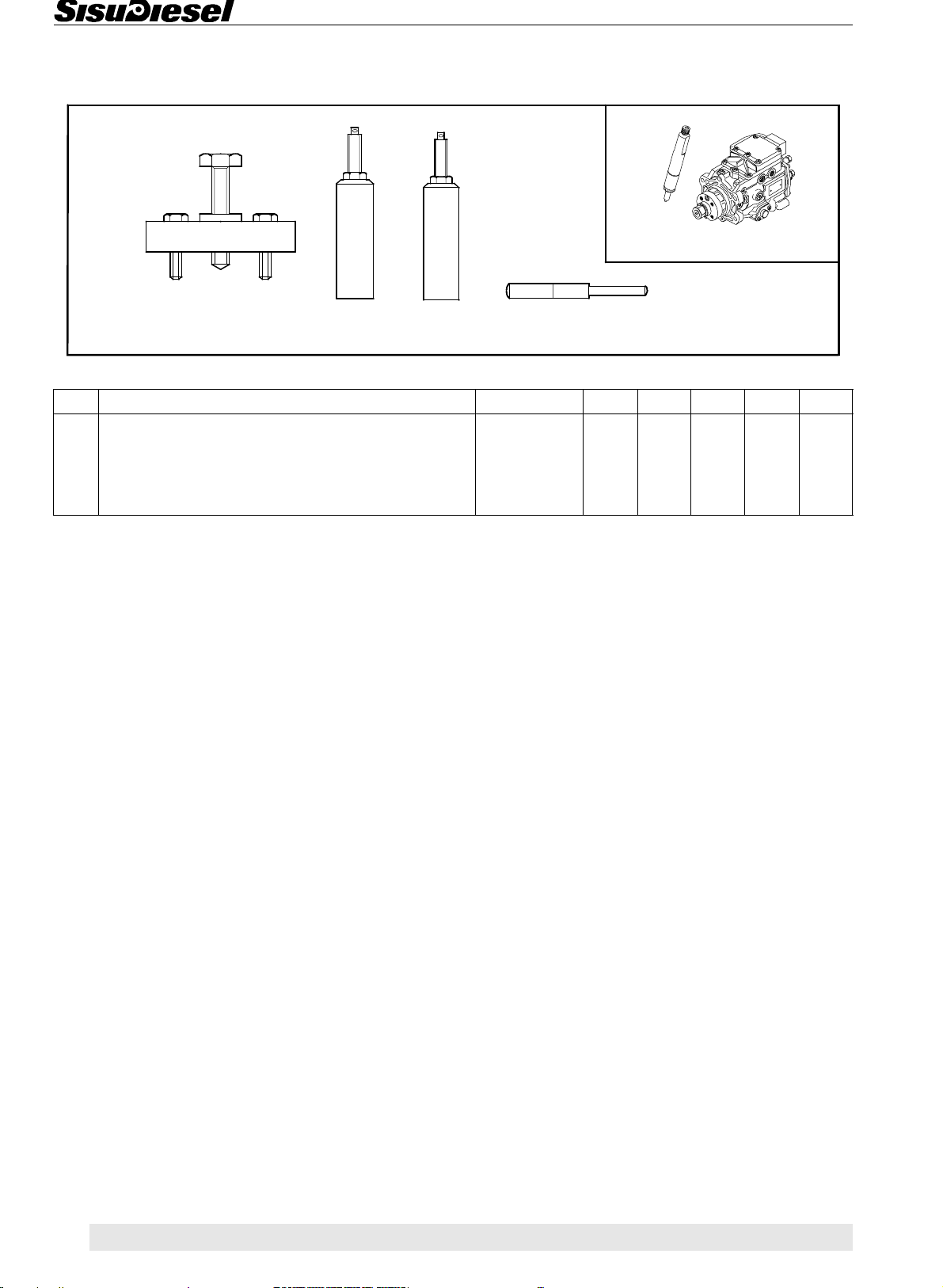
General
Fuel system
1
32
Ref.Description Order no. 3344667484
1 Puller for injection pump gear 9052 48900 x
2 Puller for injector (M12x1,5) 9051 71300 xxxx
3 Puller for injector (M14x1,5) 9104 53700 x
4 Timing pin for injection pump (Bosch VP 30 / VP 44) 9109 80100 xxxxx
4
0 33
Page 35
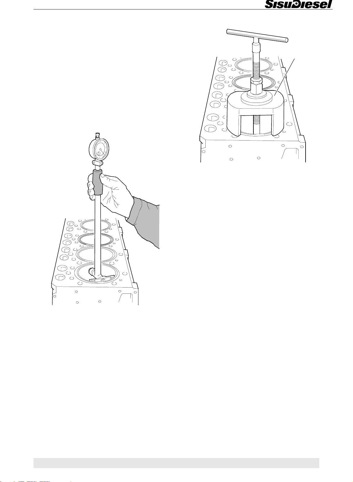
WORK INSTRUCTIONS
Cylinder Block
1. CYLINDER BLOCK
A. Measuring cylinder liner wear
1. Using a micrometer set the dial gauge to zero using
a new cylinder liner indicating the initial dimension of
the bore. See “Technical data”, point “Cylinder li-
ners”.
2. Clean the inner surface of the cylinder liner thoroughly before measurement.
9051 73100
9104 51500 (84)
2. Remove the cylinder liners using cylinder liner puller
9051 73100 or 9104 51500 (84-engines).
C. Checking cylinder block
3. Perform the measurement crosswise at the liner top
end, lower end and middle.
4. Check the gauge reading for maximum wear and
ovalness (compare with rated).
B. Removing cylinder liner
1. If the cylinder liners are to be used again they should
be marked so that they can be fitted in the same position.
1. Clean the cylinder block and all oil ways.
2. Check the cooling channels and remove the scale
and sediment to ensure engine cooling.
3. Check the tightness of the cup plugs and threaded
plugs in the cylinder block as well as the condition of the
cylinder block and sealing faces.
4. Measure the wear of the camshaft bearing points
(compare with rated).
Note! If it is necessary to machine the upper face of the
cylinder block, the pistons must be shortened by the
same dimension. Observe the valve disc spaces on the
piston upper face.
D. Changing camshaft bushing
33- and 44-engines
1. Extract the bushing with an internal puller, for example Sykes 854. If the camshaft rear end plug is removed
the bushing can be forced out with a long drift.
2. Clean the bushing location carefully.
34 1
Page 36
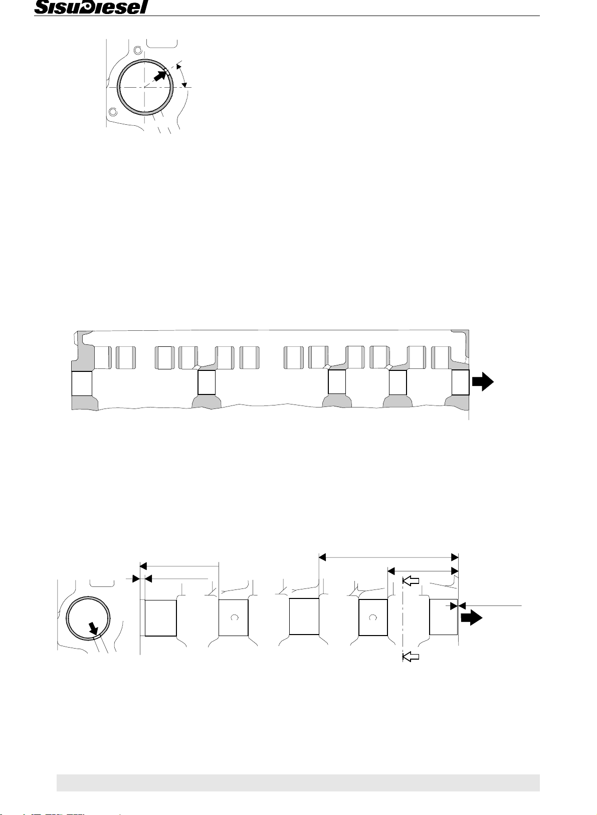
Cylinder Block
30°
3. Fit the oil hole of the bushing in 30° angle from hori-
zontal level as picture shows. It is unnecessary to ream
the bushing because it has a correct inner diameter
when it is fitted in place.
66-, 74-, and 84-engines
On the 66-, 74- and 84-engines, all camshaft bearing
points are provided with a separate bearing bushing.
1.Remove the camshaft rear end plug and tap the bushings out with a long drift. Observe the different outer diameters when removing.
2. Clean the bushings location carefully.
45
Hole diameters for the bushings. Numbering begins
from the front end of the engine.
Hole diameter
1. 55,62...55,65 mm
2. 55,42...55,45 mm
3. 55,22...55,25 mm
4. 55,42...55,45 mm
5. 55,64...55,67 mm
272 mm
A-A
7,2...8,0 mm
3
266 mm
134 mm
A
12
0,1...0,4 mm
51
4
3. Press in a new bushings (2 - 5). Observe the different
outer diameters. Note the position of the oil hole. It is
unnecessary to ream the bushing because it has a correct inner diameter when it is fitted in place.
1 35
3
2
A
Note! The cam shaft front end bushing (1) is equipped
with the oil groove on the outside. Fit the oil hole of the
bushing in 30° angle from horizontal level (see picture at
top of the page). The bushing is after assembly in its
correct measures (no need for machining).
Page 37
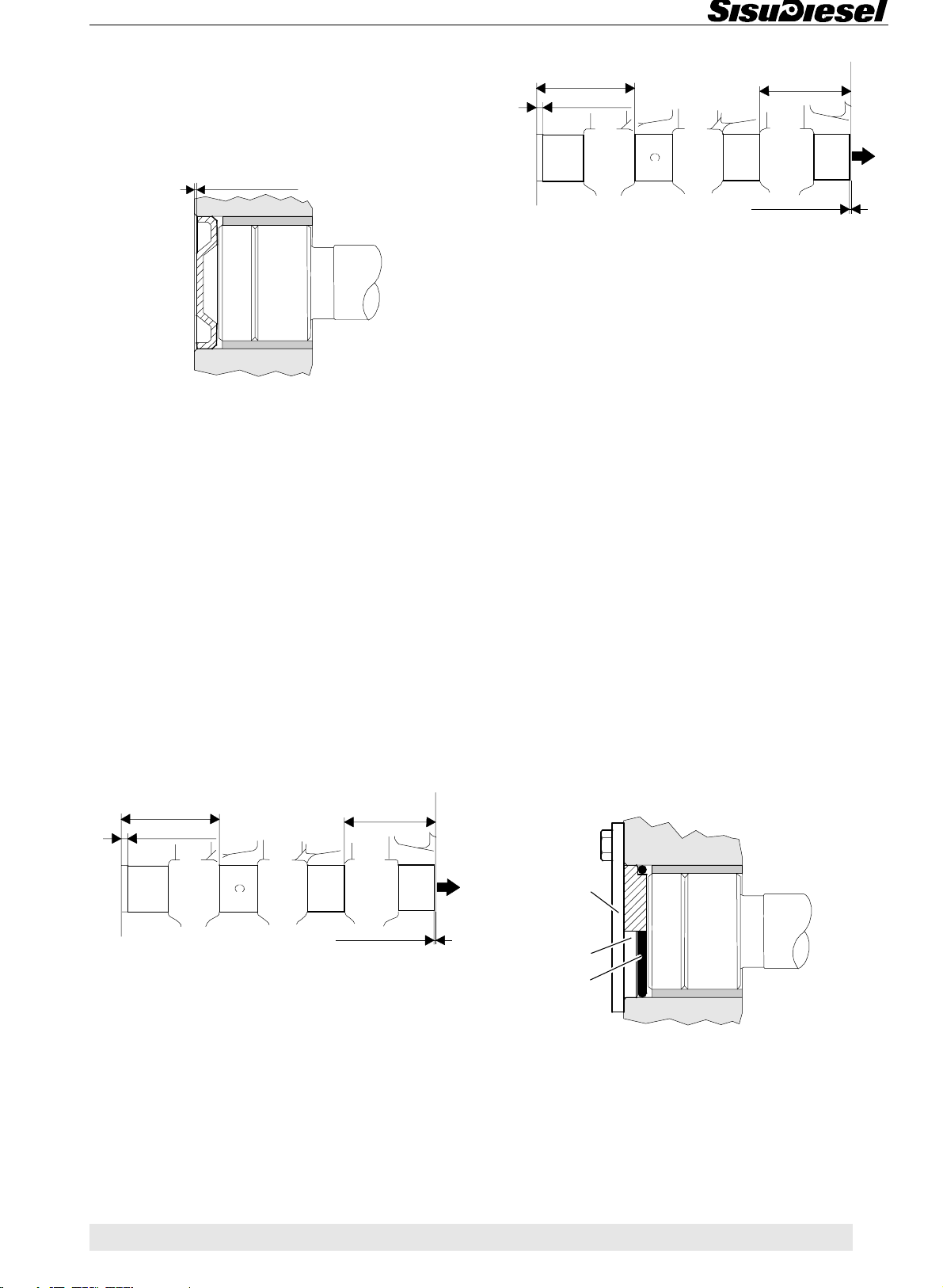
Cylinder Block
E. Fitting plug at camshaft rear end
1. Clean the seat for the plug.
2. Apply sealing compound to the contact surface of the
plug
max. 1,0 mm
3. Drive in the plug with fitting drift 9025 87400.
272 mm
7,2...8,0 mm
41
3
134 mm
2
0,1...0,4 mm
Order numbers of the oversize camshaft bushings and
hole diameters for the bushings, 44-engines. Numbering begins from the front end of the engine.
Order no. Hole diameter
1. 8368 66036 56,02...56,05 mm
2. 8368 52460 55,42...55,45 mm
3. 8368 52460 55,42...55,45 mm
4. 8368 52461 55,64...55,67 mm
Note! Do not drive in the plug too far because it will affect the camshaft end float.
F. Oversize bushings for camshaft
33- and 44-engines
If the location of the camshaft bushing (front bearing) is
damaged, a bushing with a 0,4 mm oversize outer diameter can be fitted. Bushings are available even for other camshaft bearings which do not normally have
bushings. Order numbers and machining dimensions
for the bushing locations are shown in the figure.
Observe the position of the bushing oil holes. It is unnecessary to ream the bushings after fitting.
140 mm
7,2...8,0 mm
41
3
134 mm
2
66-, 74- and 84-engines
Order numbers of the oversize camshaft bushings and
hole diameters for the bushings. Numbering begins
from the front end of the engine. Installing places are
same as with the standard bushings.
Order no. Hole diameter
1. 8368 66036 56,02...56,05 mm
2. 8368 52466 55,62...55,65 mm
3. 8368 52460 55,42...55,45 mm
4. 8368 52466 55,62...55,65 mm
5. 8368 52467 55,84…55,87 mm
G. Fitting plug at camshaft rear end (oversize bushings)
3
0,1...0,4 mm
Order numbers of the oversize camshaft bushings and
hole diameters for the bushings, 33-engines. Numbering begins from the front end of the engine.
Order no. Hole diameter
1. 8368 66036 56,02...56,05 mm
2. 8368 52460 55,42...55,45 mm
3. 8368 52460 55,42...55,45 mm
4. 8368 52461 55,64...55,67 mm
1
2
The camshaft rear end plug is replaced with plug 8363
24391 (1) and o-ring 6146 05125 (2) after machining.
Use plate 8361 24210 (3) in those engines where the
flywheel housing is not covering the blocking plug.
36 1
Page 38
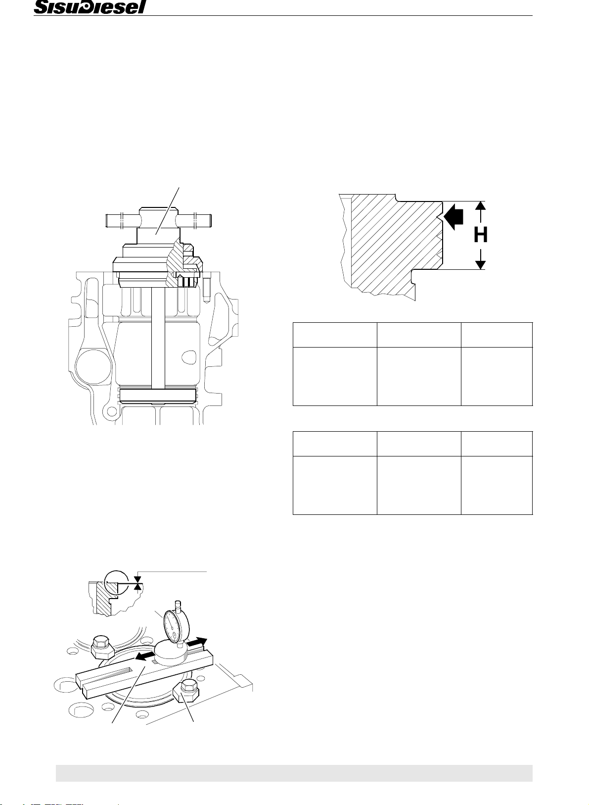
Cylinder Block
H. Fitting cylinder liner
1. Clean the cylinder liner and its recess in the cylinder
block. Without o-rings the liner should rotate easily in its
recess.
2. Apply a thin layer of marking paint on the underside
of the cylinder liner flange. Fit the cylinder liner without
o-rings and turn it forwards and backwards. Lift out the
liner and check that paint has been deposited on the
whole contact surface.
9101 65600
9104 52000 (84)
5. Fit the cylinder liners and fix each liner with two press
tools 9101 66300. Measure the cylinder liner height with
a dial gauge and holder 9025 79200. Zero the dial gauge against a flat surface, for example, the cylinder block
face. Measure each liner in four places. The height of
the liner above the cylinder block face should be
0,03...0,08 mm. The height difference between cylinder
liners under the same cylinder head must not exceed
0,02 mm, nor must an intermediate cylinder liner lie lower than an outer one.
6. If the cylinder liner height is too low, a liner with a
higher flange is fitted.
33-, 44-, 66- and 74-engines
Order no. H Marking-
grooves pcs
8366 47420
8366 47933
8366 47934
8366 47935
9,03
9,08
9,13
9,23
+0,02
+0,02
+0,02
+0,02
- (std.)
1
2
3
3. If the recess is damaged, or the cylinder liner height
(see point 5) needs to be adjusted, use milling cutter
9101 65600 or 9104 52000 (84-engines). If necessary,
a light lapping can be executed after milling with the
help of the cylinder liner. Apply lapping paste to the underside of the cylinder liner flange, and twist the liner
with twisting tool. Lapping is not suitable for adjusting
the cylinder liner height.
4. Clean the contact surfaces.
0,03...0,08 mm
84-engines
Order no. H Marking-
grooves pcs
8368 67048
8368 67050
8368 67051
8368 67052
9,03
9,08
9,13
9,23
+0,02
+0,02
+0,02
+0,02
- (std.)
1
2
3
Cylinder liners with oversize flanges (higher flanges)
are marked with grooves on the outer circumference as
follows:
1st oversize, 0,05 mm = 1 marking groove
2nd oversize, 0,10 mm = 2 marking grooves
3rd oversize, 0,20 mm = 3 marking grooves
Note! Recess depth is adjusted with a cylinder liner recess cutter 9101 65600 or 9104 52000 (84-engines).
7. If the liner height of a cylinder liner is not the same all
the way round, the cylinder liner flange and the cylinder
block recess depth should be checked. Cylinder liners
with warped flanges should be discarded.
9025 79200
9101 66300
1 37
Page 39
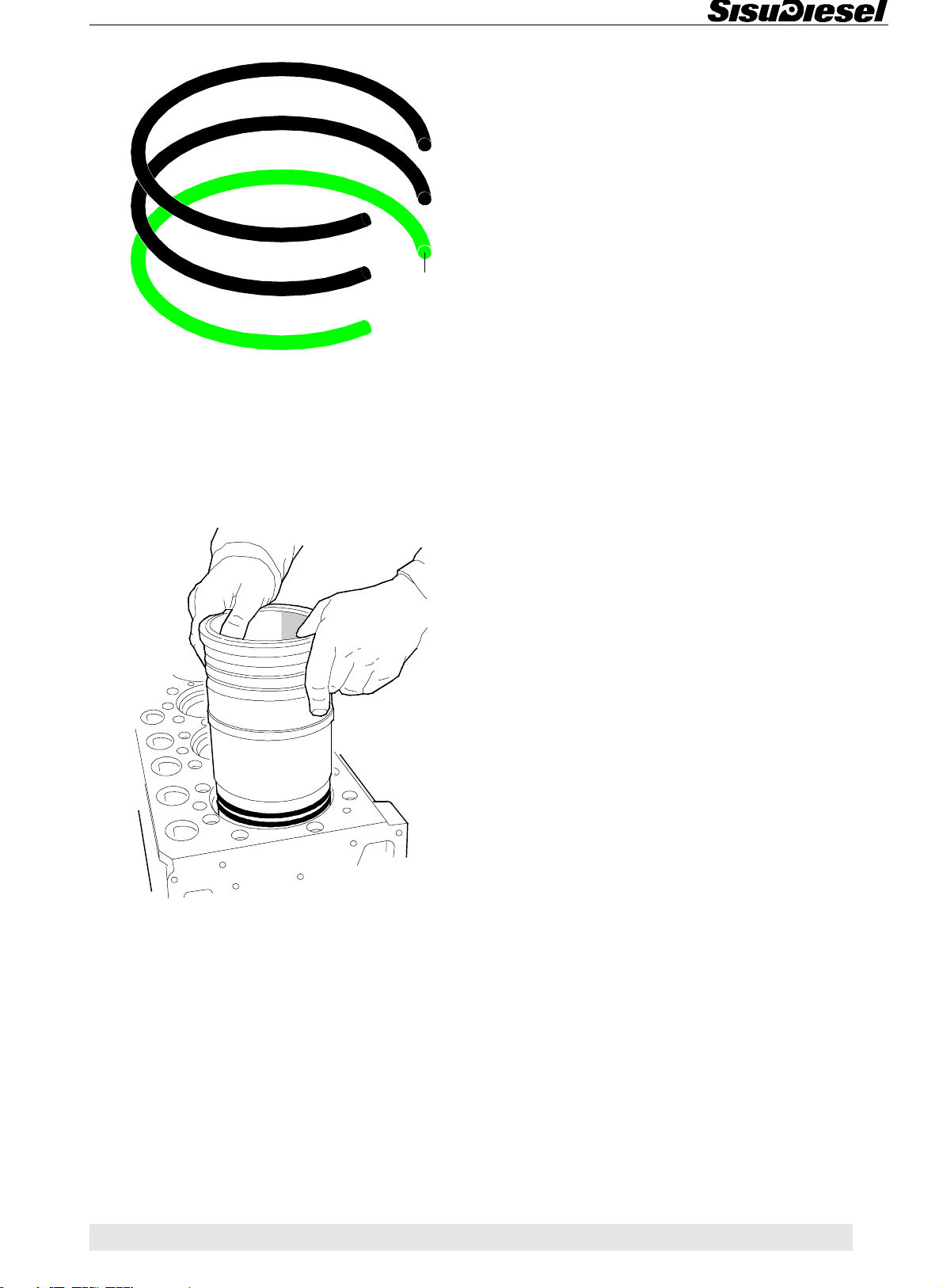
Cylinder Block
A
8. Fit the o-rings into the grooves in the cylinder liner.
84-engines, fit the o-rings into the grooves in the cylinder block. Fit the green o-ring (A) into the lowest groove. Lubricate the o-rings with a liquid soap (not with
engine oil).
Note! Stretch the o-rings as little as possible when fitting them. Max allowable stretching is 6 %.
9. Press the cylinder liners into the cylinder block. It
should be easy to press them fully home. Make sure
that the liners do not rise up after fitting.
38 1
Page 40
Cylinder Block
1 39
Page 41
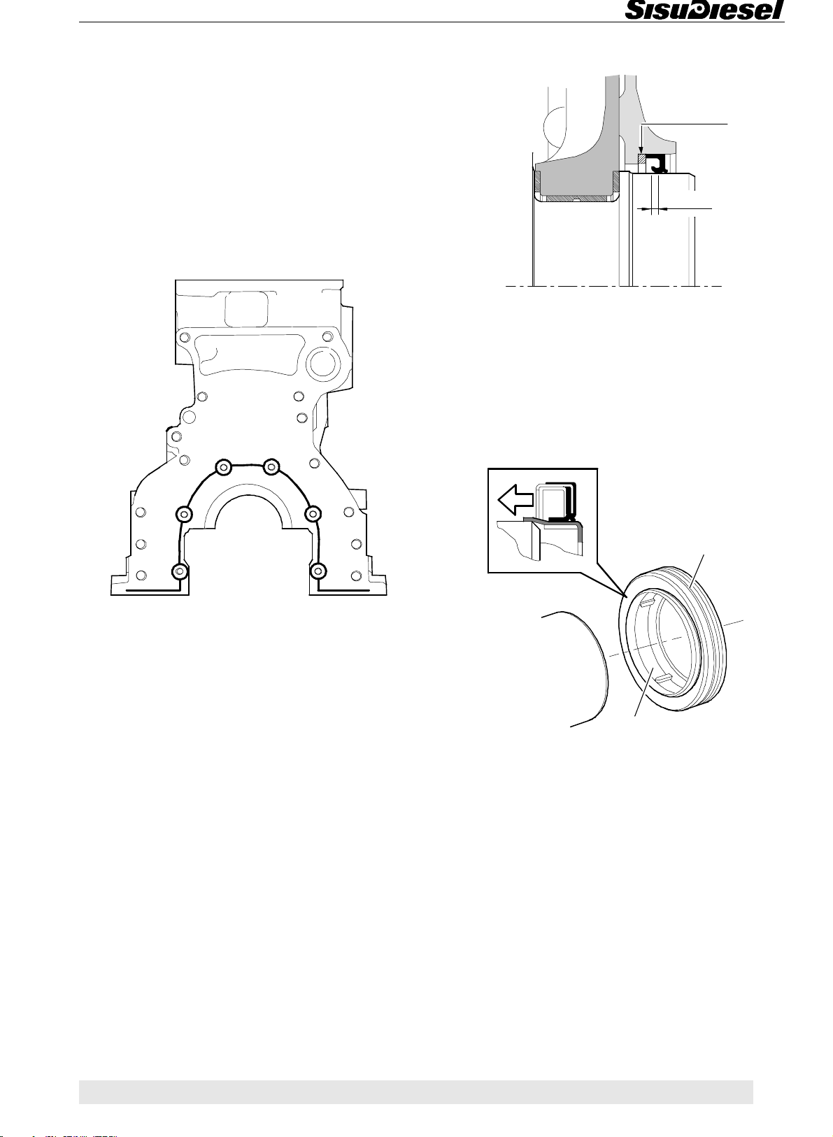
Flywheel Housing
2. FLYWHEEL HOUSING
A. Fitting flywheel housing
The flywheel housing is centred on the cylinder block by
two tension pins. Even the flywheel housings which are
delivered as spare parts have ready-made holes for the
pins.
1. Clean the sealing surfaces between the cylinder
block and the flywheel housing.
4. Clean the seal location and grind off any burrs.
8360 20054
2 mm
Note! If the crankshaft is worn at the sealing location, a
2 mm spacer ring, order no. 8360 20054, can be fitted
in front of the crankshaft rear oil seal.
5. Fit the seal as follows:
- Do not remove the plastic sleeve in before hand.
- Fit the seal dry, not oiled!
2. Apply silicone sealant as shown in picture above.
3. Lift the flywheel housing into place and fit all the bolts.
4. Centre the housing with centring tool 9052 46400 or
9104 52700 (84-engines). Note! This is important of the
engines with a turbine clutch. Fit the tension pins with
drift 9025 98700.
5. Tighten the fixing bolts, the inner ring socket head
bolts to 80 Nm and outer ring hexagonal bolts to 150
Nm.
B. Changing crankshaft rear oil seal
1. Lift out the engine. Remove the clutch assembly (and
possible turbine clutch).
2. Remove the flywheel.
B
A
- Put the sleeve (A) against the crankshaft rear end so
that the sleeve is on the shaft bevelling.
- Push the seal (B) over the sleeve on the shaft and further against the flywheel housing.
3. Remove the oil seal. Do not damage the crankshaft.
40 2
Page 42
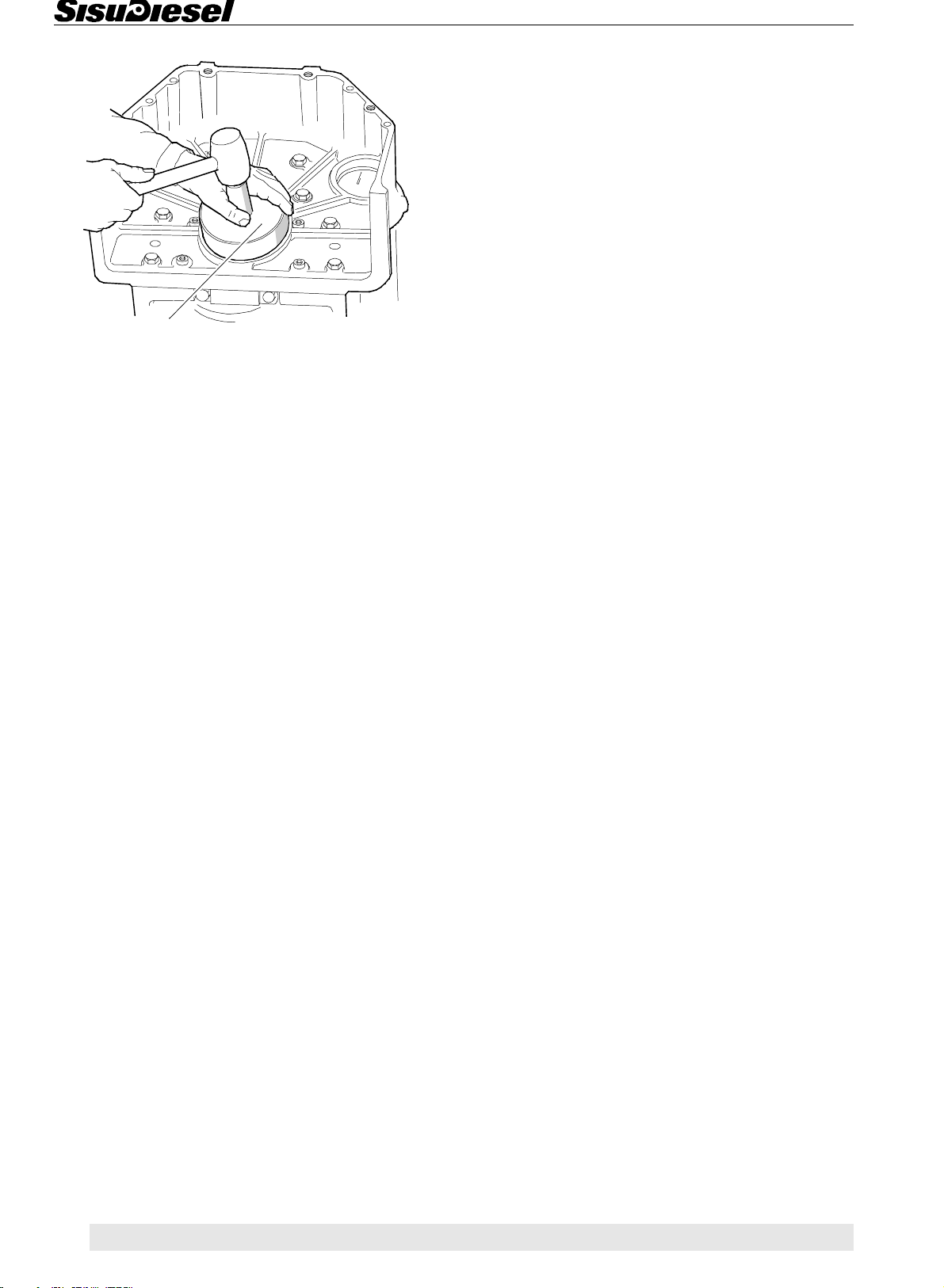
Flywheel Housing
9052 46300
9104 52600 (84)
- Remove the sleeve and hit the seal into position with
the fitting tool 9052 46300 or 9104 52600 (84-engines).
2 41
Page 43
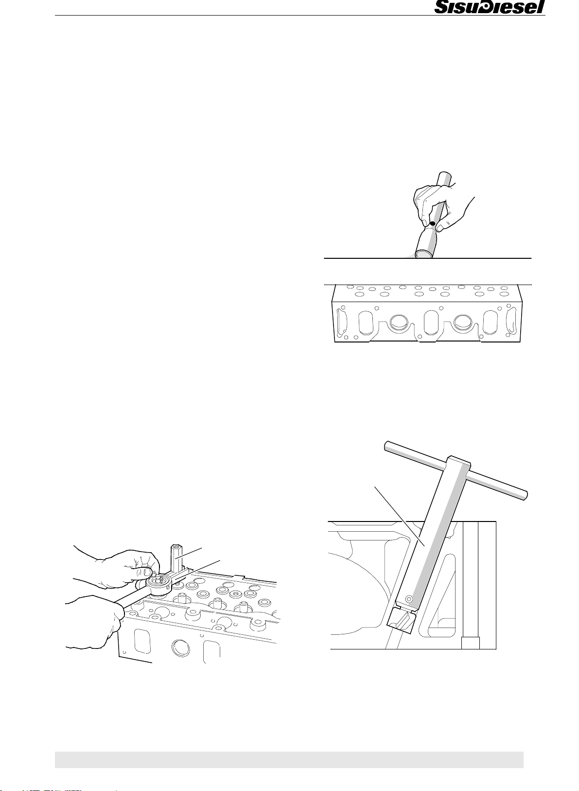
Cylinder Head
3. CYLINDER HEAD
A. Removing cylinder head
1. Clean the engine externally and drain the coolant.
Disconnect the coolant hoses from the cylinder head
and the thermostat housing.
2. Remove the suction hoses between the turbocharger
and the air filter and between the turbocharger and the
inlet manifold.
3. Disconnect the turbocharger pressure and return oil
pipes.
4. Disconnect the current from the main switch. Disconnect wires from the intake air heater.
5. Remove the injector leak-off fuel pipes and the delivery pipes. Remove the injectors. Fit blanking-off caps
on all open connections.
6. Remove the inlet and exhaust manifolds and the thermostat housing.
2. Compress the valve springs using lever 9101 66200.
Remove the valve cotters, spring guide and spring. Remove the valves.
C. Checking cylinder head
1. Remove the soot from the exhaust ports, clean the
sealing surfaces and wash the cylinder head.
2. Check for cracks and other damage.
Note! It is possible to remove the cylinder head even
thought these parts are attached to the head.
7. Remove the valve cover.
8. Remove the rocker arm mechanism and the push
rods.
9. Loosen all the cylinder head bolts first by a 1/4 turn
and then remove them. Remove the cylinder head.
B. Removing valves
Ensure that valves which are to be re-used are marked,
so that they are fitted in their original locations.
9052 47200
9101 66200
3. Check the flatness of the cylinder head by using a
straight edge. An uneven or warped surface should be
surface ground. The height of the cylinder head, after
grinding, should not be less than 104,00 mm. The valve
disc depth from the cylinder head surface should be
0,60 mm for the exhaust valves and 0,70 mm for the inlet valves.
9101 66000
1. Install the counter screw 9052 47200 for the valve
spring installing tool in the rocker arm cover bolt. On the
33-, 66-, 74- and 84-engines there is not a screw stud
at the valves for the centre cylinder. A bolt of suitable
length should be used instead.
4. Straighten and clean the injector location seat in the
cylinder head with cutter 9101 66000.
42 3
3
Page 44
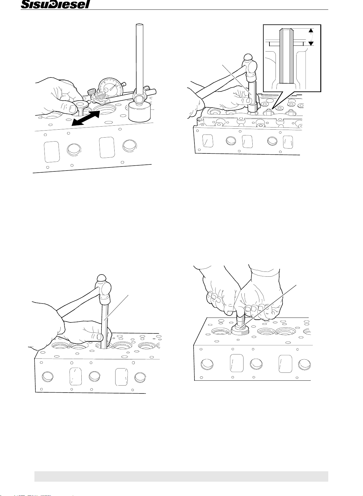
Cylinder Head
5. Measure the clearance between the valve stem and
the valve guide with a dial gauge. Lift the valve so that
the valve head is 15 mm from the face of the cylinder
head, and measure the clearance. It must not be greater than 0,30 mm for the inlet valves and 0,35 mm for
the exhaust valves. In order to establish the valve guide
wear, a new valve should be used when measuring.
21 mm
9101 65900
2. Lubricate the outside of the new guides and fit them
using drift 9101 65900, which ensures the correct fitting
height (21 mm over the spring face).
3. The guides are the same for the inlet and exhaust valves. Ensure that the steepest chamfer on the guide, faces the valve head. Check that the valves do not bind in
the guides.
D. Changing valve guides
9101 65800
1. Press or knock out the old guides using drift 9101
65800. Clean the valve guide locations.
E. Machining valve seat
9101 66100
Machine the damaged valve seat with milling cutter. If
the width of the seat exceeds 2,3 mm in exhaust and
3,7 mm in intake, it should be reduced primarily at the
outer edge.
3 43
The valve seat angle is 45°
+20'
35°
for inlet valve.
+20'
for exhaust valve and
Page 45
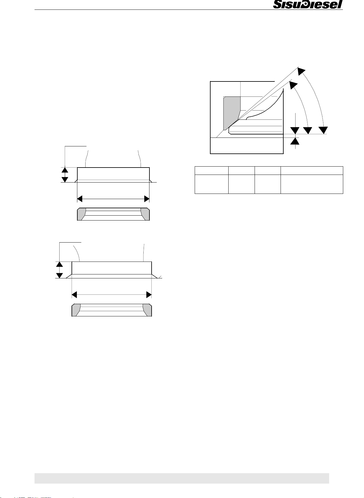
Cylinder Head
F. Changing valve seat rings
Exhaust valves are fitted with separate valve seat rings.
Also the engines with high output are equipped with separate inlet valve seats. If the sealing surface is damaged so badly that it cannot be repaired with machining,
the seat ring should be changed.
1. Grind the valve head on a discarded valve so that it
sits down in the valve seat. Fit the valve and weld it in
place in the seat. Cool with water.
2. Turn the cylinder head over and knock out the valve
and seat.
Exhaust
10,1 mm
44,000...44,025 mm
Inlet
±0,1
mm
11
G. Grinding valves
In order to ensure that there is a proper seal around the
valves, there is a difference in the sealing surface angles. Thus there is a very narrow sealing surface which
seals effectively even after prolonged running.
B
A
C
ABC (mm)
Inlet
Exhaust
35°
45°
-20'
-20'
1. Grind the damaged valve disc with a valve refacer.
Adjust angles to 45°-20' for exhaust valves and 35°-20'
for inlet valves.
2. If the edge of the valve head is less than 1,5 mm after
it has been ground, or if the valve stem is bent, the valve
should be discarded.
35°
45°
+20'
+20'
0,7
0,6
±0,05
(max. 2,20)
±0,05
(max. 2,20)
48,500...48,525 mm
3. Clean the valve seat location. Cool the new seat ring
in liquid nitrogen until it stops bubbling, or alternatively
place it in dry ice.
4. Fit the seat with a suitable drift. Machine the seat.
Note! Where necessary, standard size seats can be
replaced by inserts with a larger outer diameter. See
“Technical data”, point “Cylinder head”.
The inlet valve seat machined direct on the cylinder
head, can be provided with a separate valve seat ring,
order no. 8366 47936. Machine the seat insert location
on the cylinder head (see picture above). Fit the insert
like a seat of the exhaust valve.
3. If necessary, grind the end of the valve stem.
4. Lap the valves with lapping paste and check the contact surface with marking paint.
5. Clean the cylinder head and valves of any remaining
lapping paste.
H. Fitting valves
1. Check the valve springs for straightness, length and
tension using a spring tester. See “Technical data”,
point “Valves, rockers and tappets”.
2. Lubricate the valve stems and fit the valves in the correct order in the cylinder.
3. Fit the springs, spring guides and valve keepers with
the aid of a lever for compressing valve springs, 9101
66200.
4. Tap the end of the valve stems lightly after fitting the
valve in order to ensure that they are secure.
44 3
Page 46
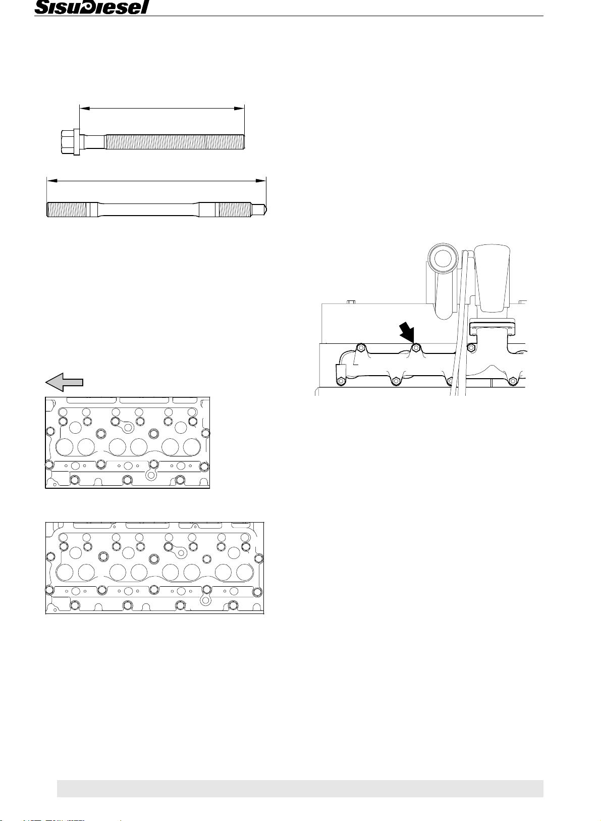
Cylinder Head
I. Fitting cylinder head
1. Measure the length of the cylinder head bolts. Compare with dimensions shown in figure below. Change
too long bolts.
max. 142 mm
max. 188,5 mm
2. Screw the cylinder head stud bolts in to the cylinder
block to a torque of 30 Nm. Fit the valve tappets if removed.
3. Check that the sealing surfaces are clean and fit the
cylinder head gasket(s) and the cylinder head(s). Ensure that on the six cylinder engines both cylinder heads
are parallel by fastening lightly the exhaust manifold before tightening the cylinder head bolts (the exhaust manifold can damage, if the heads are not parallel). Clean
and lubricate and fit the bolts.
5. Tighten the cylinder head bolts progressively as follows:
1. First tightening to 80 Nm
2. Tightening of 90°
3. Tightening again of 90°.
6. Adjust the valve clearances (see instruction 4 C).
7. Run the engine with a light load to the normal running
temperature (~75°C).
8. Tighten the bolts 60° and adjust the valve clearances.
Note! After this the cylinder head does not need retightening.
50 Nm
Engine front end
10 7
14
16
12
8
33, 66, 74, 84
19
22
21
20
18
44
59
31
2
12
10
8
4
6
6
2
1
3
15
17
13
11
14
11
4
7
9
5
17
16
15
13
4. Pictures above show the correct tightening order of
the cylinder head bolts. The order has also been marked on the cylinder heads.
Tighten the exhaust manifold nuts to 50 Nm. Do not
overtighten!
3 45
Page 47
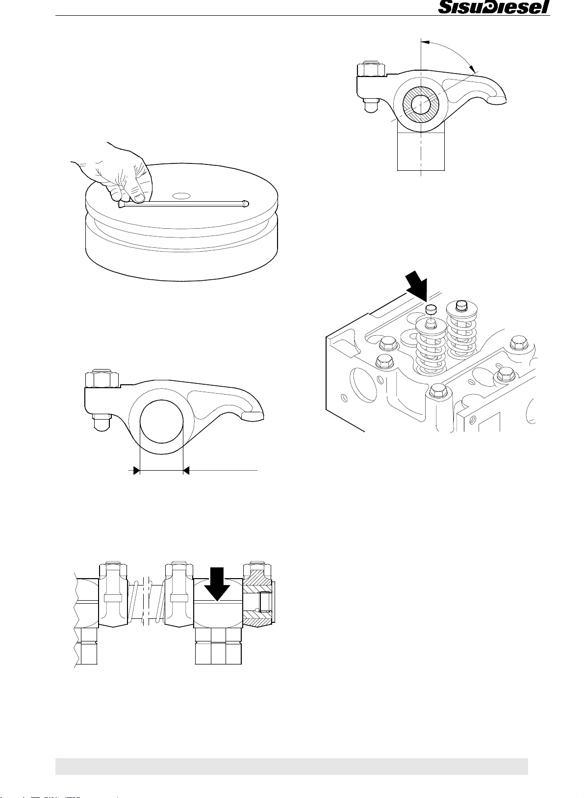
Valve Mechanism
4. VALVE MECHANISM
A. Reconditioning valve mechanism
1. Check the valve tappets, especially the contact surface against the camshaft. Worn or damaged tappets
should be discarded.
2. Check the straightness of the push rods by rolling
them on a surface table. Check also the spherical surfaces at the ends.
60°
5. Fit the plug to the other end of the rocker arm shaft.
Lubricate the shaft and fit various parts in a correct order. Note the correct position of the shaft and the bearing brackets. The split side of the bracket and the shaft
oil holes must be turned to the valve side (see pictures
above). Fit the other end plug.
3. Dismantle and clean the rocker arm mechanism.
Check the shaft for wear and that the oilways are clean.
23,000...23,021
4. Check diameter of the rocker arm bore,
23,000...23,021 mm. Change the worn or damaged
rocker arm. Where necessary grind the rocker arm valve contact surface to the correct shape. Do not grind
more than necessary as the hardened layer is thin.
Note! The valves can be fitted with a separate caps.
B. Changing camshaft / camshaft gear
1. Remove the valve cover. Remove the rocker arm
mechanism.
2. Remove the radiator, cooling fan, alternator and the
V-belt.
3. Remove the V-belt pulley, the crankshaft nut and the
hub (with damper).
84-engines, remove the belt pulley and damper.
Slacken the crankshaft nut. Do not remove it! Remove
the hub using puller 9104 53300. Take off the puller,
open the nut and remove the hub.
4. Remove the timing gear casing cover (engine front
cover).
46 4
4
Page 48
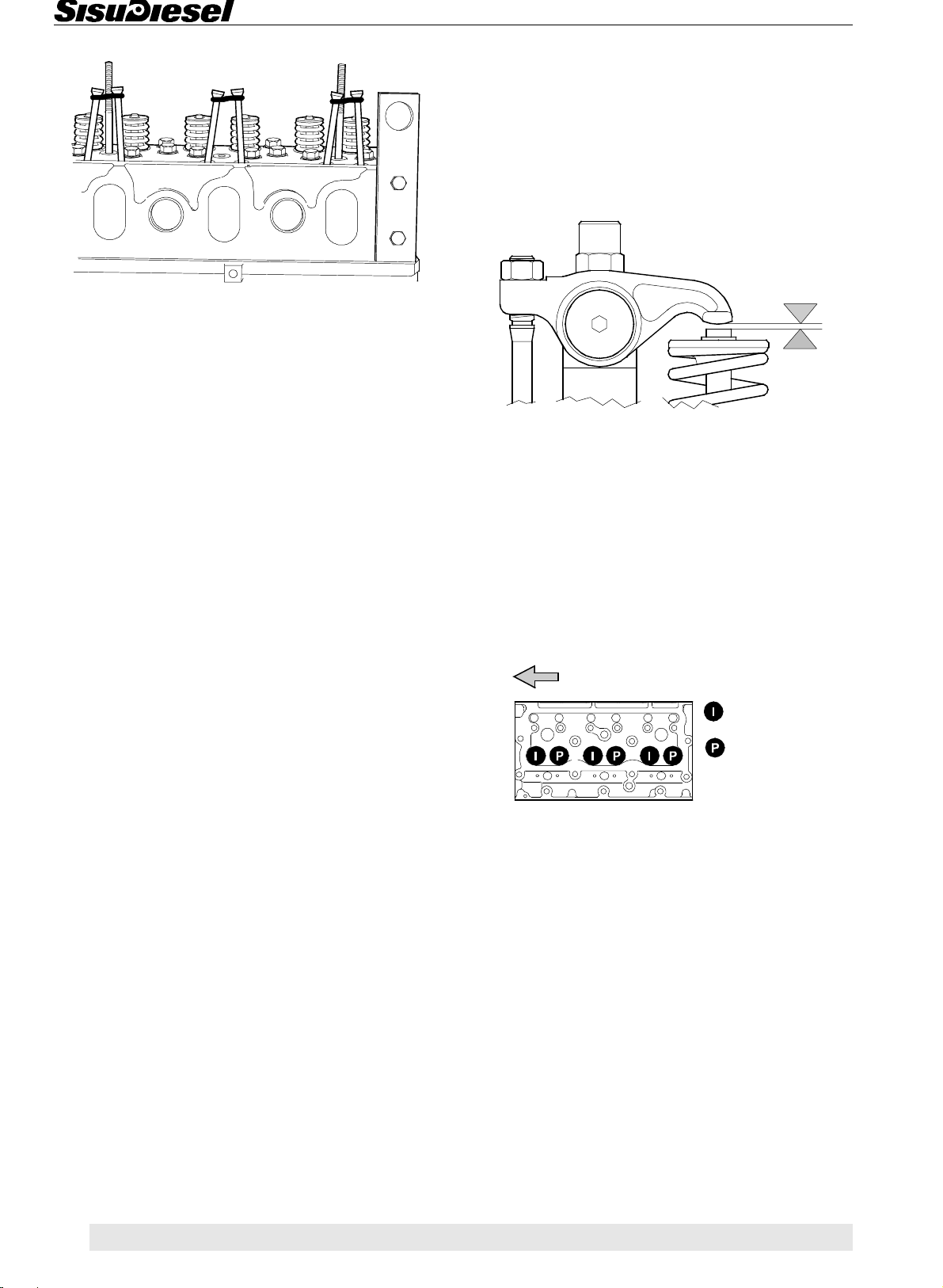
Valve Mechanism
C. Adjusting valves
The valve clearance, which can be adjusted on a hot or
cold engine, is 0,35 mm for both inlet and exhaust val-
ves. The clearance is adjusted when the respective piston is at T.D.C. in the compression stroke. The valves
for the different cylinders are adjusted in the same sequence as the order of injection.
5. Connect the push rods in pairs, using o-rings or elastic bands to prevent them from falling through.
Note! Do not connect the push rods too tightly as this
might cause them to bend or snap.
6. Crank the engine until the aligning marks on the idler
gear and camshaft gear are facing each other. Extract
the camshaft.
7. Separate the camshaft from the gear wheel using a
press or suitable drift.
8. Clean the parts which are to be refitted.
9. Fit the key in its groove. Heat the camshaft gear to
200°C in an oven and fit it on the shaft.
10. Lubricate bearing surfaces and lobes and insert the
shaft in the cylinder block. Ensure that the aligning
marks on the gears agree.
11. Fit the timing gear casing cover, the hub, damper
and crankshaft V-belt pulley.
0,35
Adjusting
• Loosen the locknut on the adjusting screw.
• Check the clearance with a feeler gauge and
adjust to the correct clearance by turning the
adjusting screw.
• Tighten the locknut and again check that the clearance is correct.
33-engines
Engine front end
INLET
EXHAUST
12. Free the push rods and fit the rocker arm
mechanism. Adjust the valves. Fit the valve cover.
13. Fit the other removed parts.
4 47
33
Check the valve clearances in the injection order of the
engine. Injection order is 1 - 2 - 3.
• Check valves in the 1st cylinder, when the exhaust
valve of no. 3 cylinder is completely open (valve
no. 6).
• Check valves in the 2nd cylinder, when the
exhaust valve of no. 1 cylinder is completely open
(valve no. 2).
• Check valves in the 3rd cylinder, when the exhaust
valve of no. 2 cylinder is completely open (valve
no. 4).
Page 49
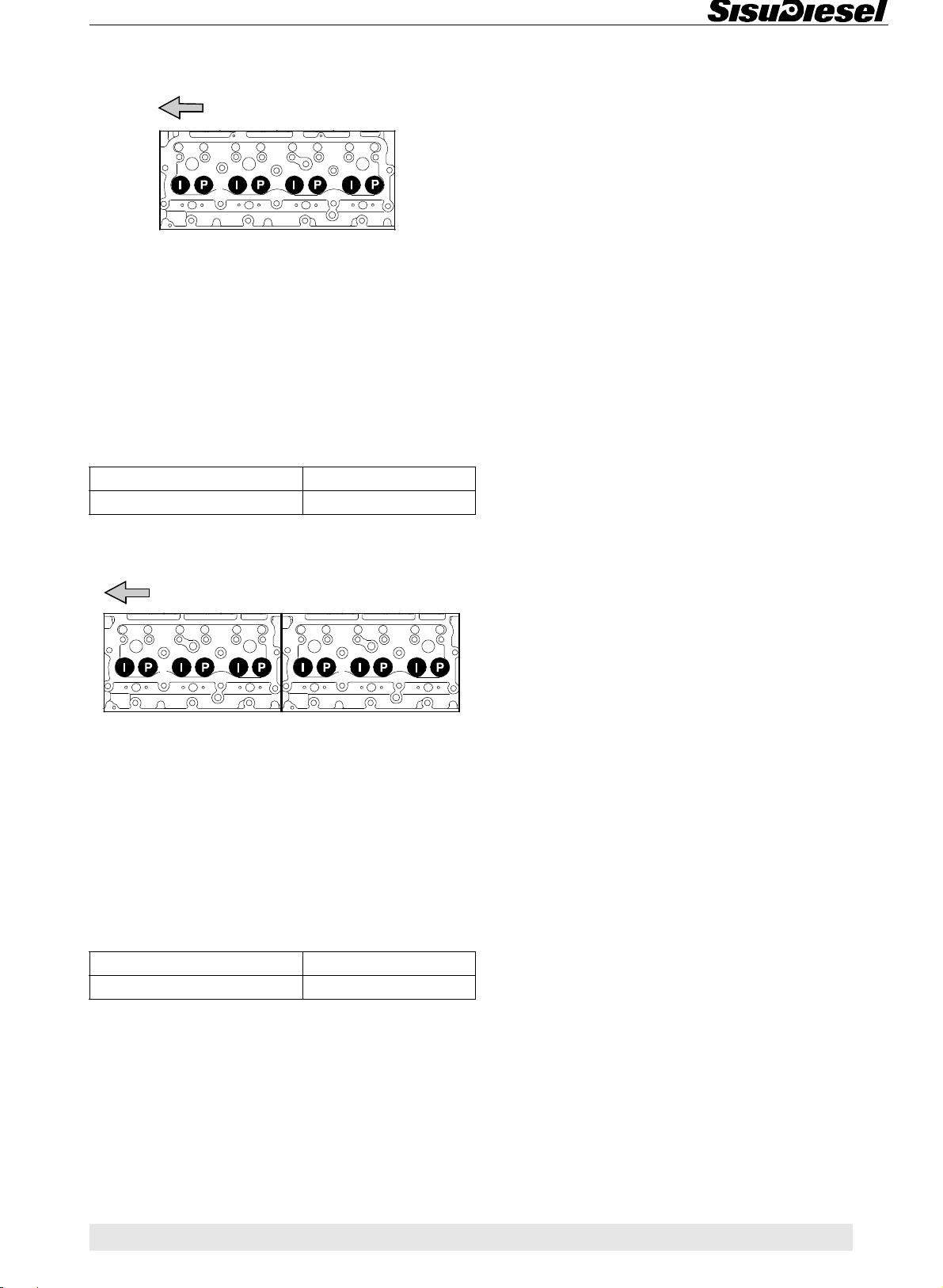
Valve Mechanism
44-engines
44
• Rotate the crankshaft in the running direction until
the valves in the 4th cylinder are rocking (exhaust
closes, inlet opens). Check the valve clearance of
the 1st cylinder.
• Rotate the crankshaft by 1/2 of a turn in the running direction so that valves in the 3rd cylinder are
rocking. Check valves in the 2nd cylinder.
• Continue according to the order of injection:
Injection order 1 - 2 - 4 - 3
Valves rock in cyl. no. 4 - 3 - 1 - 2
66-, 74- and 84-engines
66, 74, 84
• Rotate the crankshaft in the running direction until
the valves in the 6th cylinder are rocking (exhaust
closes, inlet opens). Check the valve clearance of
the 1st cylinder.
• Rotate the crankshaft by 1/3 of a turn in the running direction so that valves in the 2nd cylinder are
rocking. Check valves in the 5th cylinder.
• Continue according to the order of injection:
Injection order 1 - 5 - 3 - 6 - 2 - 4
Valves rock in cyl. no. 6 - 2 - 4 - 1 - 5 - 3
48 4
Page 50
Valve Mechanism
4 49
Page 51
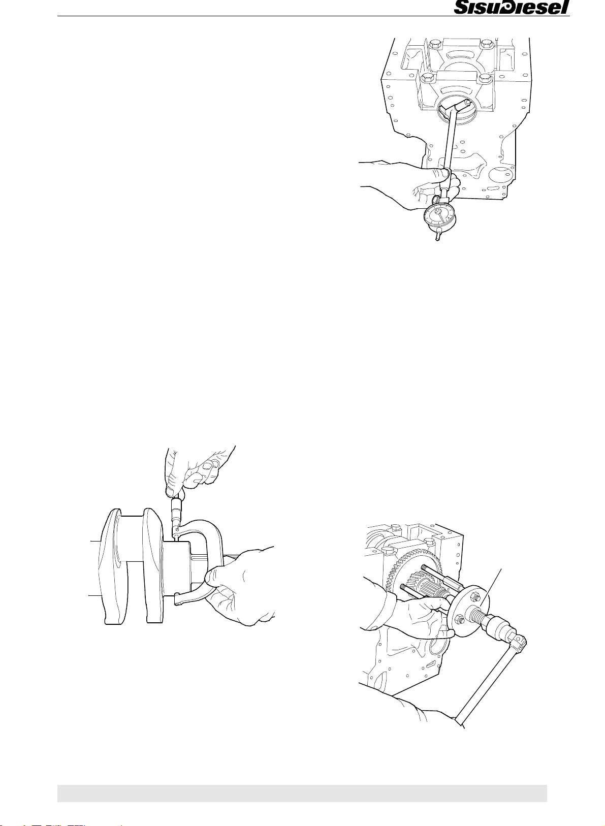
Crankshaft
5. CRANKSHAFT
A. Removing crankshaft
1. Remove the oil sump.
2. Disconnect the balancing unit lubricating oil pipe from
the cylinder block and unscrew the balancing unit fixing
bolts. Remove the balancing unit and the lubricating oil
pipe (only 44-engines).
3. Unscrew the lubricating oil pump pressure pipe fixing
screws from the cylinder block. Remove the oil pump
and the suction and pressure pipes.
4. Remove the flywheel and the flywheel housing.
5. Detach the belt pulley and the hub from the crankshaft front end. Remove timing gear housing. (see
instruction 9 A).
6. Remove the connecting rod bearing caps and push
the connecting rods out of the way of the crankshaft.
4. If the bearing clearance exceeds 0,18 mm for main
bearings or 0,14 mm for connecting rod big-end bearings with new bearing shells, the bearing journals on
the crankshaft should be ground. Refer to the specifications for the relevant correct undersize and the corresponding bearings, see “Technical data”, point
“Crankshaft”.
7. Remove the main bearing caps and lift out the crankshaft.
B. Checking crankshaft
1. Clean the crankshaft. Do not forget the oilways.
2. Measure the journal wear in several points. Out-ofround, taper or other wear must not exceed 0,03 mm.
Note! When grinding note that the journal edges must
remain round.
Note! If needed, also the main bearing can be fitted with
outer diameter 1,0 mm oversize and inner diameter 0,5
mm undersize. Order no. is 8361 40950. The main bearing housing is machined to 92,000...92,025 mm and
crankshaft to 84,485...84,520 mm. (Special bearings
not available for 84-engines.)
C. Changing crankshaft gears
9052 48800
3. Refit the bearing caps with new bearing shells and
tighten them to the correct torque. Measure the I.D. with
a dial gauge which has been zeroed to the dimensions
obtained in point 2. With this method the indicator
shows the actual bearing clearance. Measure in several
points in case the worn bearing housing is not round.
1. Apply puller 9052 48800 for the crankshaft gears and
pull off both gears.
50 5
5
Page 52
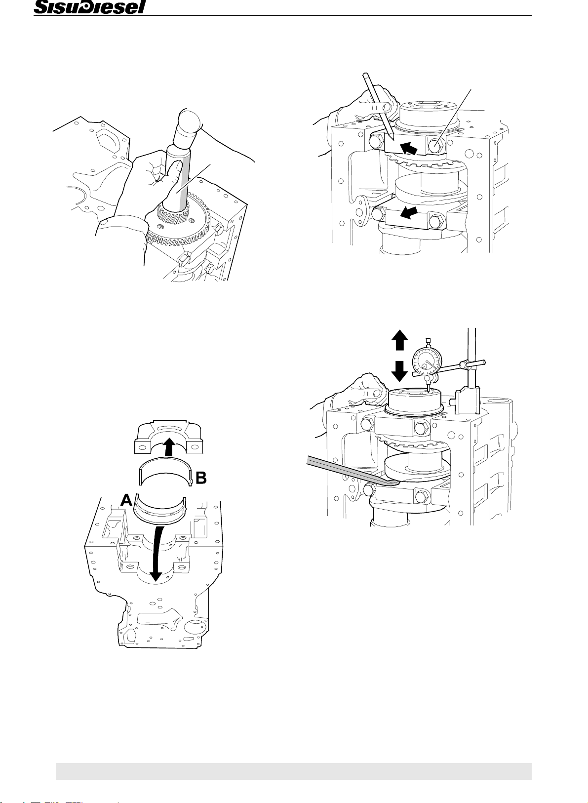
Crankshaft
84-engines, break the crankshaft gears using e.g. a
grinder. Grind the gears enough. Hit the gears apart
with a chisel. Do not damage the crankshaft!
2. Clean the seat on the crankshaft with, for example, a
wire brush.
9103 94700
3. Heat the new gears to 220...250°C. Tap them onto
the shaft with drift 9103 94700. Note the position of the
key and ensure that the aligning marks on the front gear
are visible. Leave it to cool.
3. Lubricate the bearing surfaces and fit the crankshaft.
Fit the crankshaft thrust bearings with the lubricating
grooves facing the crankshaft.
200 Nm
7
6
4. Fit the main bearing caps according to their numbering (bearing lock in the block and in the cap are on the
same side), the rear with thrust bearings provided with
guide lugs. Lubricate the bolts and tighten them to
200 Nm.
D. Fitting crankshaft
1. Clean the oilways, bearing shells and bearing locations. Check that the crankshaft is clean.
0,10...0,38 mm
5. Check that the crankshaft can rotate without binding.
Check the end float using a dial gauge. The correct end
float is 0,10...0,38 mm. If the end float is too large, oversize thrust bearings should be fitted.
Note! Bearing shells should never be reamed or machined in any other way, nor should the sides of the
bearing caps be filed
2. Assembly the bearing with oilholes/groove (A) to the
cylinder block and the bearing with no hole (B) to the
bearing cap. Ensure that the bearing shell clamping
claws fit into their notches and that the shells to be fitted
in the cylinder block have a hole coinciding with the oil
port.
5 51
Note! 33-engines, tightening torque of screws of crank-
shaft counterweight is 160 Nm. Apply locking fluid (e.g.
Loctite 2701) on the screw threads.
Page 53
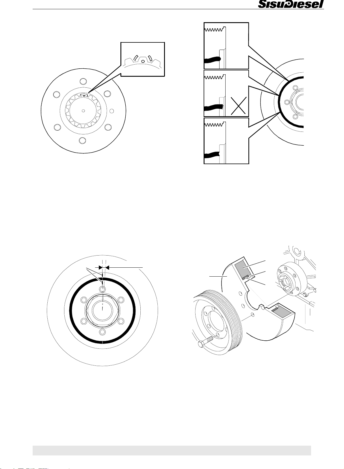
Crankshaft
E. Crankshaft hub piece
When fitting the hub piece to the crankshaft front end
note the correct position of the hub (engines with the
installation mark of the injection pump on the crankshaft
pulley/vibration damper). The hub piece has an installation mark - on two teeth and the corresponding installation mark o of the crankshaft is on one tooth.
OK
OK
OK
2. Check also the condition of the rubber element. If
rubber pieces have been loosened from the element,
rubber has been pressed to the depth of more than
3,5 mm or the outer circumference is slack or it moves
in the direction of the shaft, change the damper.
F. Checking element of the rubber damper
44- and 66-engines
A
1. Check the alignment marks (A) on both sides of the
rubber element. If the difference is more than 1,5 mm,
change the damper for a new one.
max. 1,5 mm
G. Viscose type vibration damper
66-, 74- and 84-engines
2
3
1
4
1. Housing 3. Liquid cavity
2. Damper mass 4. Bushing
In the 74- and 84-engines and some 66-engine versions
there is a vibration damper of so-called viscose type. Inside the damper there is a housing filled with stiff silicone oil in where the damping substance is situated with
very small tolerances.
52 5
Page 54
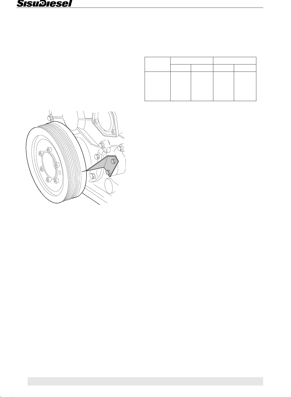
Crankshaft
Note! Even a small dent makes the vibration damper
inoperative. Do not remove it by turning forcibly and be
careful not to damage it when it is loose. If you detect a
dent on the outer surface, do not install the damper
back in the engine.
Note! Note! Make the installation mark of the injection
pump on the vibration damper with an electric pen (do
not tap).
H. Changing crankshaft pulley / vibration damper
5. Make the installation mark of the injection pump on
the vibration damper/pulley with an electric pen (do not
tap).
Piston distance (h) from top dead centre vs. crank angle
(α) with different injection pumps.
Engine
type
44 30° 10,213
66 30° 10,213
74 30° 11,692 26° 8,865
84 28° 10,997
Bosch VP 30 Bosch VP 44
α h (mm) α h (mm)
1. Loosen the alternator fixing screws and remove the
v-belt.
2. Open the bolts of the pulley/vibration damper and remove the parts. The pulley/vibration damper is positioned to the crankshaft hub with a tension pin.
3. Fix the new vibration damper/pulley on the crankshaft. Tap the tension pin in its place and tighten the fixing screws to a torque of 30 Nm.
Note! Vibration dampers (pulleys) delivered as spare
parts do not have the installation mark of the injection
pump. Make the marking on the new damper in connection with installation.
4. Rotate the crankshaft until the piston of the 1st cylinder reaches its top dead centre. Drop cyl. no. 1 inlet valve down against the piston head. Set the dial gauge on
top of the valve stem end and zero it at the piston top
dead centre. Then rotate the crankshaft opposite to running direction until dial gauge shows about 15 mm below TDC. After that rotate the crankshaft slowly to
running direction until the dial gauge shows the figure
corresponding injection timing (see table below).
5 53
Page 55
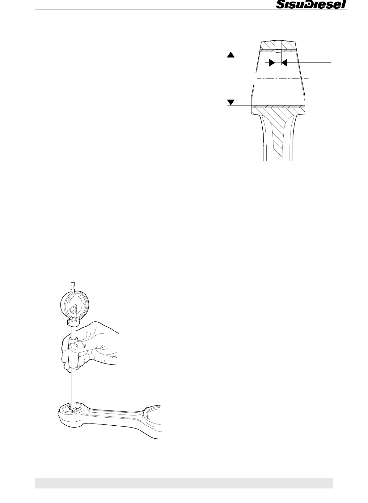
Connecting Rods and Pistons
6. CONNECTING RODS AND PISTONS
A. Removing pistons together with connecting rods
1. Remove the oil sump and the oil inlet and pressure
pipes.
2. Remove the cylinder head.
3. Scrape off the possible soot in the cylinder liner. If
the turning edge is clearly marked, smooth it down carefully with a scraper.
4. Remove the big-end bearing caps and bearing shells.
Place the shells in order if they are to be re-used.
5. Push up the piston and connecting rod with the shaft
of a hammer or similar wooden tool.
6. Remove the piston pin snap rings. Push out the pin.
Note! If the piston pin does not move under thumb
pressure the piston should be heated to 100°C.
3. If the piston pin bushing is worn, it should be driven
out using a suitable drift
Ø5 mm
Ø4 mm (84)
40,025...40,040 mm
44,025...44,040 mm (84)
4. Press the new bush in its place. Ensure that the oil
hole in the bush coincides with the respective hole in
the connecting rod. After fitting drill oil hole (84-engines)
and ream the bush to attain its correct diameter.
Note! The connecting rod can, if needed, be fitted with
a 0,5 mm oversize bushing. See “Technical data”,
point “Connecting rod”.
B. Changing connecting rod bearings
Piston pin bushing
1. Clean the connecting rod and bearing shells.
Big end bearing
1. Fit the bearing shells together and tighten the screws.
2. Measure the I.D. using a cylinder gauge which has
been zeroed to the diameter of the respective bearing
journal. If the clearance exceeds 0,14 mm with new
bearing shells, the big end journals require grinding.
Refer to the specifications for the correct undersize and
the corresponding bearing.
Note! Ensure that the radii at the end of the bearing
journals is not altered when grinding.
C. Checking connecting rod
The connecting rod is checked in a special fixture, intended for the purpose (e.g. Carl Larsson). See
“Technical data”, point “Connecting rod”.
2. Measure the I.D. of the piston pin bushing using a cylinder gauge.
54 6
6
Page 56
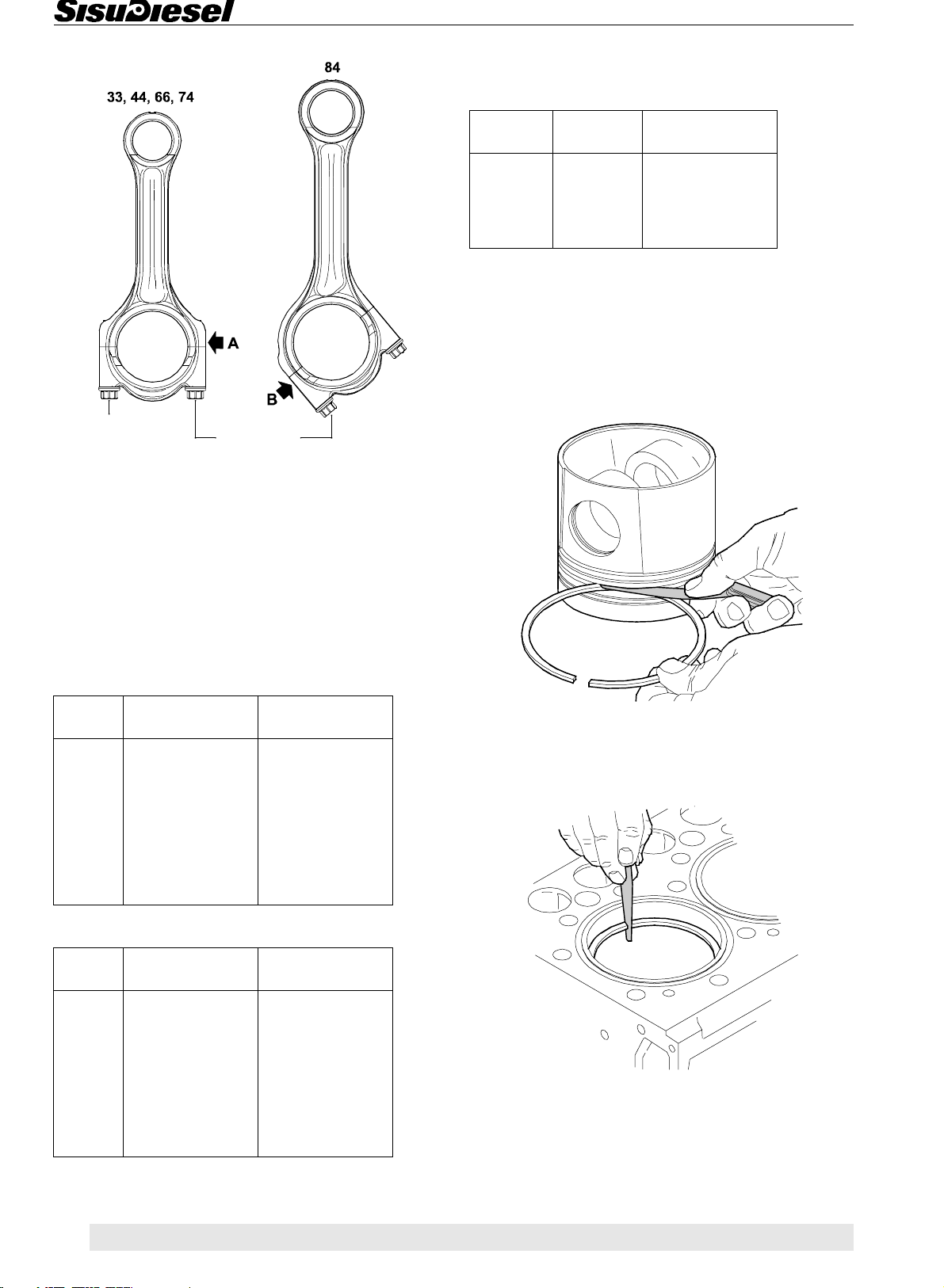
Connecting Rods and Pistons
The order number of the connecting rod kits as spare
part are as follows:
Torx E18
40 Nm + 90°
Note! Always change the screws when opened.
The connecting rods are divided into weight classes
with intervals of 20 g. The weight class (a letter) is stamped on the side face of the connecting rod. All the connecting rods in one engine should be of the same
weight class, that is to say the greatest permissible
weight difference is 20 g.
Engine
type
33 3 8366 40968
44 4 8367 40859
66, 74 6 8368 40928
84 6 8363 40948
Number
of cyl.
Order no.
D. Changing piston rings
1. Remove the piston rings with piston ring pliers 9052
46900. Do not open the rings more than necessary. If
the rings are to be used again ensure that they are fitted
in the same groove.
The letters show the weight classes as follows:
33-, 44-, 66- and 74-engines
Letter
(A)
W 8366 66434 2015 - 2034 g
84-engines
Letter
(B)
Order no. Weight
F 8366 66430 1935 - 1954 g
V 8366 66431 1955 - 1974 g
X 8366 66432 1975 - 1994 g
Y 8366 66433 1995 - 2014 g
Z 8366 66435 2035 - 2054 g
G 8366 66436 2055 - 2074 g
Order no. Weight
E 8368 64101 2230 - 2249 g
F 8368 64102 2250 - 2269 g
G 8368 64103 2270 - 2289 g
H 8368 64104 2290 - 2309 g
I 8368 64105 2310 - 2329 g
J 8368 64106 2330 - 2349 g
K 8368 64107 2350 - 2369 g
2. Clean the piston ring grooves and measure the piston
ring clearance, which must not exceed 0,15 mm. Determine whether too large a clearance is due to worn rings
or a worn groove. Change worn parts.
3. Measure the piston ring gap by pushing one piston
ring at a time into the cylinder bore. The piston ring gap
must not exceed 1 mm on 1. and 3. piston rings and 1,5
mm (84-engines, 1,3 mm) on 2. piston ring.
6 55
Page 57
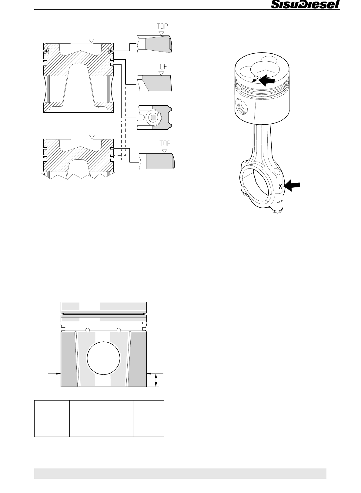
Connecting Rods and Pistons
F. Fitting piston pin
DS
D
4. Fit the piston rings on the piston using the piston ring
pliers. Ensure that the rings are fitted in the correct
groove and that "TOP", or the manufacturer's designation, faces upwards.
1. Place the connecting rod inside the piston and push
the piston pin into place.
E. Checking pistons
Check the condition of the pistons and piston pins. Pay
special attention to possible cracks on the edge of the
combustion chamber and on the upper edge of the piston pin hole. Measure the diameter of the piston at the
point shown in the figure below. Renew a piston if needed.
ØD
h
The combustion chamber and the weight class letter
should be on same side.
Note! 84-engines, the combustion chamber and the
weight class letter should be on opposite sides.
2. Fit the piston pin circlips. Ensure the circlips are pressed correctly into the grooves. The circlip ends must
point upwards.
G. Fitting piston together with connecting rod.
1. Check that the bearing locations are clean and place
the bearing shells in the connecting rod and bearing
cap. Note the position of the bearing shells.
2. Lubricate piston, rings and cylinder bore. Ensure that
the piston ring gaps are spread around the piston.
Engine D (mm) h (mm)
33, 44, 66 107,873...107,887 17,0
74 107,893...107,907 19,0
84 110,863...110,877 15,0
56 6
Page 58
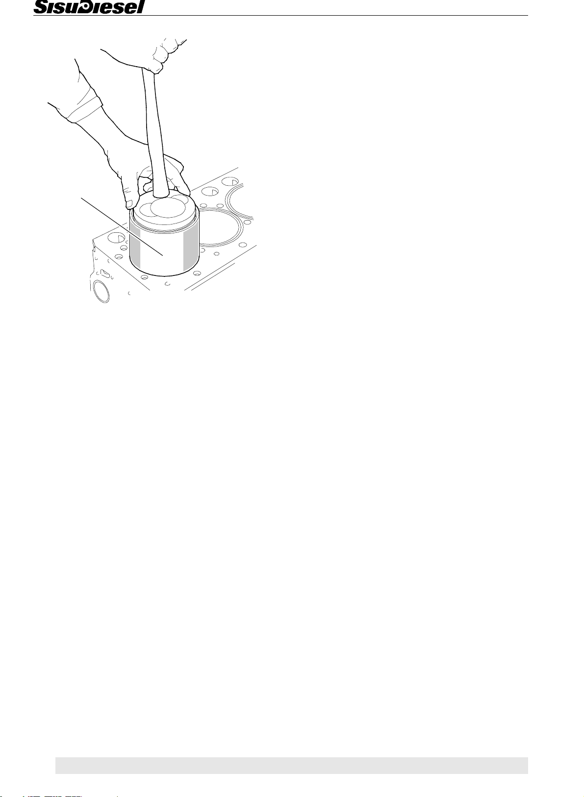
9020 01100
9105 18700 (84)
Connecting Rods and Pistons
3. Use a piston ring strap or preferably a fitting tool 9020
01100 or 9105 18700 (84-engines). Fit the piston with
the connecting rod so that the combustion chamber and
the fuel injector are on the same side (an arrow on the
piston must point forward).
4. Lubricate the big-end bearing journal and bearing
shells, and push the piston down. Fit the bearing cap so
that the notches for the guide lugs are in the same side.
Tighten the connecting rod screws to 40 Nm + 90°.
5. Check that the connecting rod has sufficient end float
on the big-end bearing journal.
6 57
Page 59
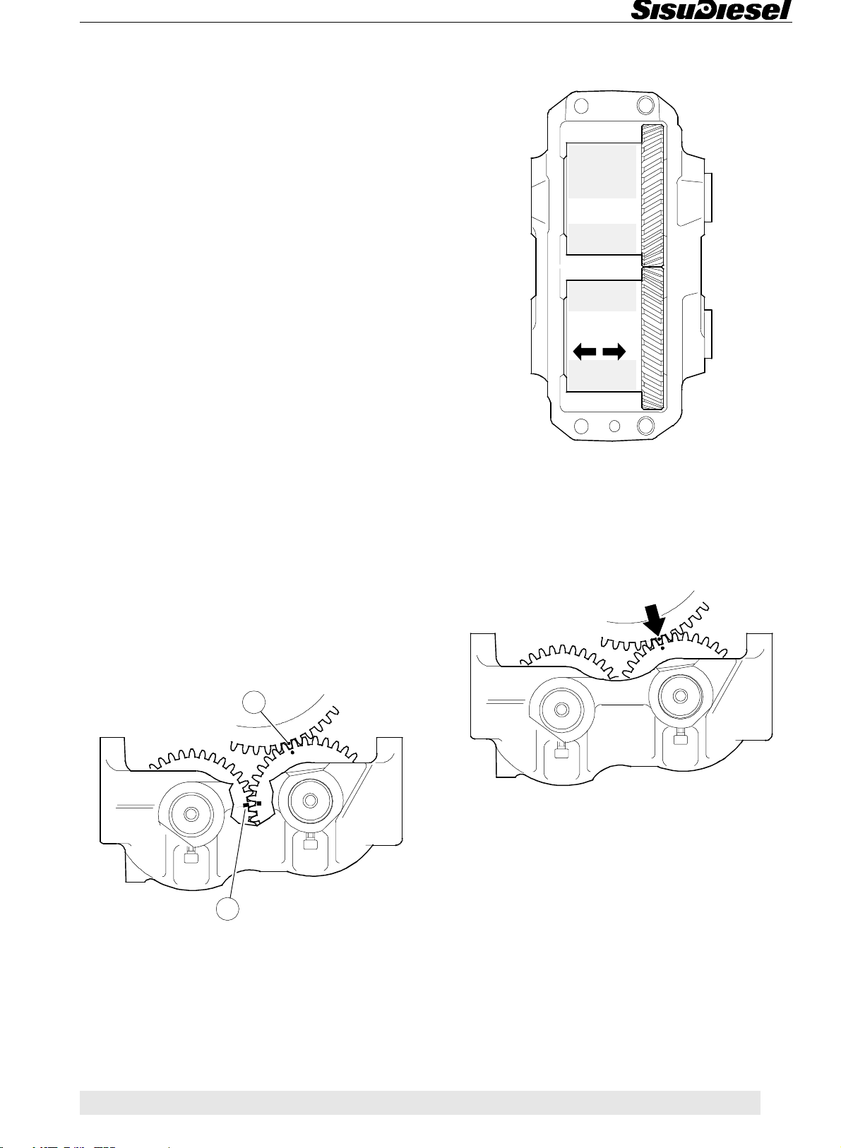
Counterbalance
7. COUNTERBALANCE (44-engines)
A. Removing and disassembling counterbalance unit
1. Remove the oil sump
2. Disconnect the lubricating oil pipe of the counterbalance unit.
3. Remove the counterbalance unit. Take care of any
shims.
4. Loosen the locking screws and press out the shafts
in the direction of the locking screws. Remove the counterweights and thrust washers.
5. Clean all parts.
B. Reconditioning counterbalance unit
Check the shafts, gear wheels and bushings for wear
and damage.
rings. Apply thread lock fluid (e.g. Loctite 270) to the
locking screws, and lock the shafts.
0,1...0,3 mm
4. Check that the tooth backlash is 0,05...0,25 mm and
that the end float is 0,1...0,3 mm.
1. If one of the gear wheels is damaged, change both
counter weights as a complete unit. The gear wheels
are not available separately as a spare part.
2. Remove, if necessary, the old bearing bushings with
a suitable drift. Before removing them, mark the position
of the bushing oil groove on the counter weigh. Press in
new bushings in the correct position. After fitting the
bushings should be reamed to a correct dimension, see
Specifications.
2
1
1. Synchronisation marking (notch)
2. Marking against crankshaft (punch mark)
3. Place the weights in the body, observing the notch
markings. The gear wheel with the punch mark runs
against the crankshaft and should therefore be placed
highest. Insert the shafts, remembering the thrust bea-
C. Fitting counterbalance unit
1. Fit the tension pins to the cylinder block.
2. Turn the crankshaft and weights so that the markings
agree, and lift the unit into place.
3. Tighten the screws to 60 Nm. Check that the tooth
backlash between the crankshaft and counterweight is
0,1...0,3 mm. The backlash can be increased by placing shims 0,2 mm thick (order no. 8361 19920) between the cylinder block and balancer unit body. One
shim (0,2 mm) changes tooth backlash about 0,07 mm.
4. Fit the lubricating oil pipe, using new seals.
5. Fit the oil sump.
58 7
7
Page 60
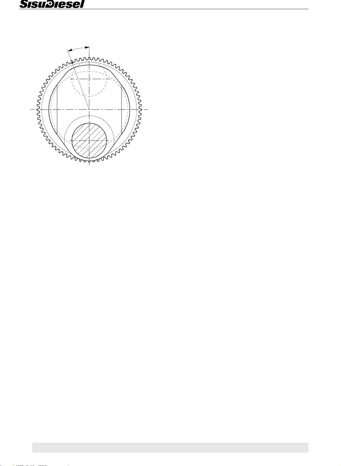
D. Changing crankshaft gear rim
20°
Counterbalance
1. Mark the position of the gear rim on the shaft.
2. Heat the gear rim with a welding torch and drive it off
using a suitable drift.
3. Heat the new gear rim to max. 250°C. Fit the gear rim
with the chamfer facing the crankshaft flange, and with
the teeth according to markings or according to figure
above. Tap the gear rim down and leave it to cool.
Note! The picture above shows a rear view of the
crankshaft and no. 2 cylinder big end bearing journal.
7 59
Page 61
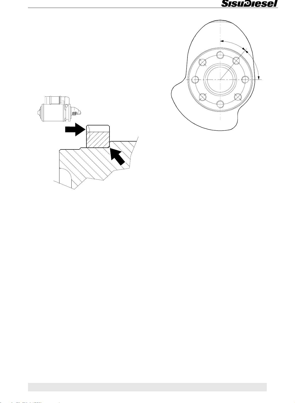
8. FLYWHEEL
Flywheel
A. Changing starter ring gear on flywheel
If the ring gear is worn, change it with a new one. The
ring gear cannot be turned around because its teeth are
chamfered and hardened on the starter motor side.
1. Remove the old starter ring by tapping it at various
points with a drift. Clean the flywheel contact face with
a steel-wire brush.
40°
50°
Note! 84-engines, the flywheel fixing bolt holes are unsymmetrical.
3. Tighten the flywheel retaining screws evenly to a torque of 150 Nm (200 Nm, 84-engines).
2. Warm the ring gear to the temperature of
150...200°C. Fit the ring gear with the inner diameter
chamfering turned against the flywheel and the teeth
chamfering against the starter motor.
3. Allow the ring gear to cool freely without using any
coolant.
B. Fitting flywheel
1. Clean the contact surfaces on the crankshaft rear
flange and on the flywheel.
2. Fasten the flywheel to the crankshaft rear end. As a
guide pins can be used suitable studs (2 pcs) which are
screwed in to the flywheel fixing bolt holes.
60 8
8
Page 62
Flywheel
8 61
Page 63
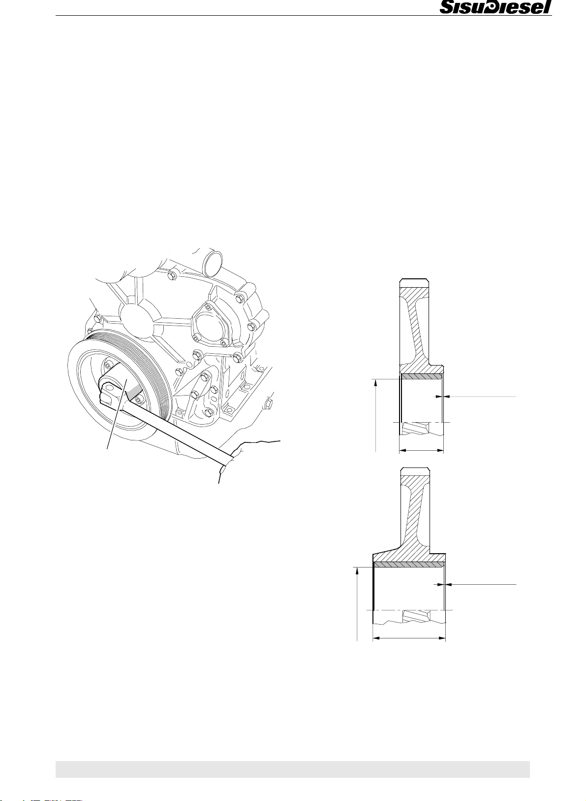
Timing Gear Assembly
9. TIMING GEAR ASSEMBLY
33-, 44-, 66- and 74-engines
A. Removing timing gear casing
As the timing gear casing bottom face forms a part of
the mating face for the oil sump gasket, the casing cannot be removed without first removing the oil sump.
1. Drain the engine oil and remove the oil sump.
2. Remove the radiator, fan, alternator, belt tensioning
and belt (if not removed earlier). If the engine is equipped with an air compressor or air conditioner, it has to
be removed.
7. Unscrew the idler gear bolts (17 and 22 mm). Remove the flange, gear wheel and bearing journal.
8. Extract the camshaft.
Note! If the cylinder head and valve mechanism have
not been removed, the tappets must be prevented from
falling down, see instruction 4 B.
9. Remove the timing gear casing. Ensure that all sealing surfaces are not damaged.
10. Remove the crankshaft front sealing ring from the
front casing and clean all the parts that have been removed.
B. Reconditioning idler gear
9101 65700
9024 55800
3. Loosen the crankshaft nut (special tool 9101 65700
for 33-, 44- and 66-engines or tool 9024 55800 for 74engines). Remove the hub (with belt pulley).
Note! On 66-engines the belt pulley must be removed
before unscrewing the nut. If the 66-engine is equipped
with a viscose damper, the front end nut is opened with
tool 9024 55800.
4. Remove the drive unit and hydraulic pump (if installed).
5. Remove the timing gear casing cover and the oil deflector ring at the front end of the crankshaft.
6. Remove the injection pump. See instruction 13 C.
0,10...0,25 mm
Ø55,00...55,03
Ø55,20...55,23
If the idler gear bushing is changed, press in a new
bushing so that its rear edge is 0,1...0,25 mm inside the
gear wheel rear edge.
30 mm
0,10...0,25 mm
50 mm
Note! If the timing gear casing is not to be changed, the
injection pump can remain in place. In which case disconnect all leads and pipes from the pump.
62 9
9
Page 64
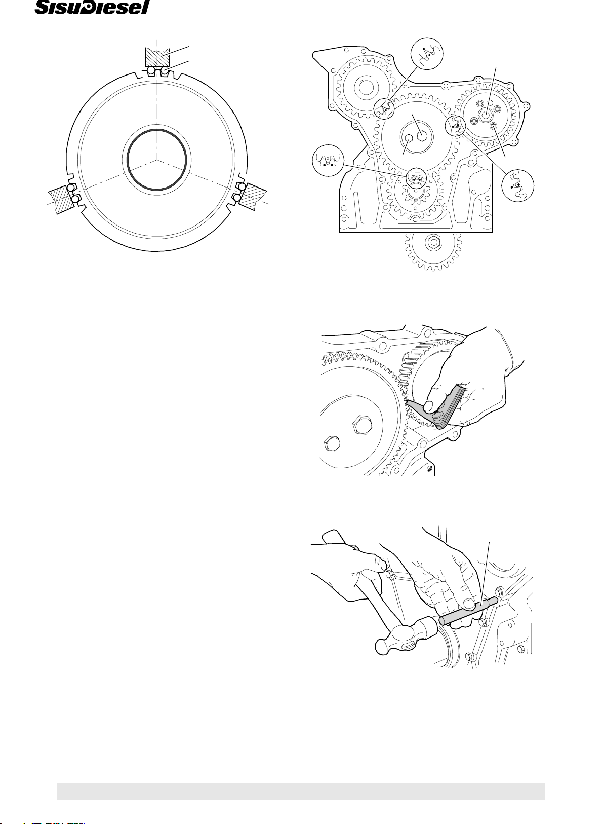
Timing Gear Assembly
1
2
200 Nm
Do not open!
1. Chuck of lathe
2. Roller 5 mm
Machine the idler gear bushing inner diameter to a correct dimension after fitting. Centre the idler gear according to figure above so that tooth backlash is kept the
same.
C. Fitting timing gear casing
The position of the timing gear casing and cover is determined by two tension pins. Therefore centring should
not be undertaken in connection with fitting. However,
the tooth backlash between the different gears should
be checked. Casing and covers that are delivered as
spare parts also have holes for the tension pins already
machined.
1. Fit the casing with a new gasket against the cylinder
block. Drive in the tension pins with drift 9025 98700.
Tighten bolts and nuts.
60 Nm
4. Fit the idler gear with shaft stud and ensure that the
markings are in the correct position. Fit the washer and
tighten the bolts to the correct torque.
5. Check the tooth backlash which should be
0,05...0,25 mm.
9025 98700
9025 98800
35 Nm
2. Fit the injection pump together with gear wheel (if removed).
3. Lubricate the camshaft bearings and insert the shaft
in the cylinder block. Release the push rods and tappets
if they have been suspended.
9 63
6. Fit the oil deflector ring on the crankshaft and fit the
timing gear casing cover using a new gasket. Drive in
the tension pins with drifts 9025 98700 and 9025 98800
respectively (the tubular pin round the screw stud).
Tighten bolts and nuts.
Page 65
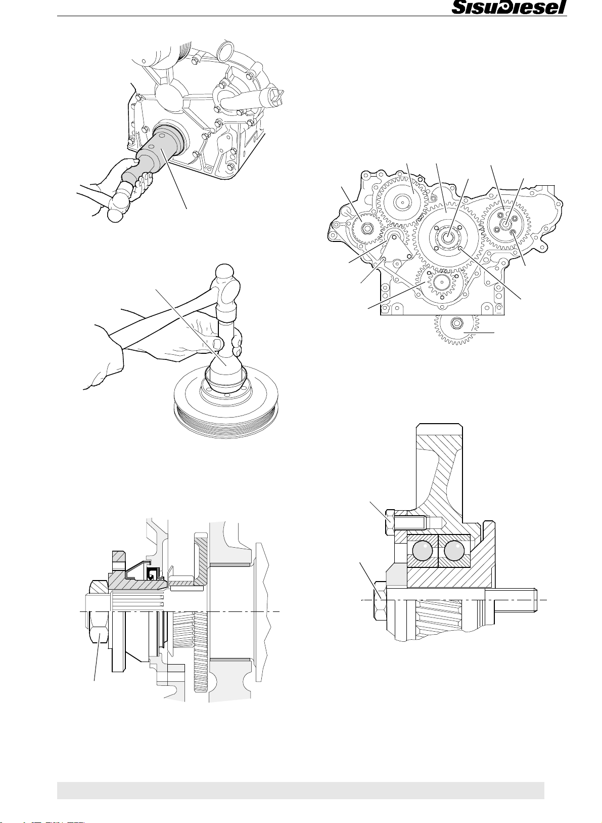
Timing Gear Assembly
11. Fit the other detached parts.
D. Idler gear with bevelled ball bearings
In some 66- and 74-engines versions bevelled ball bearings are need in the idler gear. The two-cylinder compressor, fitted to the gear housing, is run trough a
separate rear.
9030 15200
7. Fit the protective plate into the seal location and fit the
crankshaft front seal with special tool 9030 15200.
9025 98900
12
180 Nm
7
6
30 Nm
4
3
Do not open!
35 Nm
22 Nm
5
1. Camshaft gear 5. Oil pump gear
2. Idler gear 6. Idler gear of compressor
3. Injection pump gear 7. Compressor gear
4. Crankshaft gears
8. Fit the dust shield on the crankshaft hub, if it has been
removed. Use drift 9025 98900.
9. Lubricate both the seal and sealing surfaces and fit
the crankshaft hub (with belt pulley).
600 Nm (33, 44)
1000 Nm (66, 74)
10. Lubricate the crankshaft nut threads. Tighten the
nut to 600 Nm on 33- and 44-engines and 1000 Nm on
66- and 74-engines.
22 Nm
180 Nm
1. Fit the idler gear bearings, as the picture shows,
pressing from the outer ring. Fit the holding ring and
tight the bolts, lightly oiled, to 22 Nm. Press the shaft to
its position supporting the bearing from the inner ring.
The idler gear screw tightness is 180 Nm.
64 9
Page 66
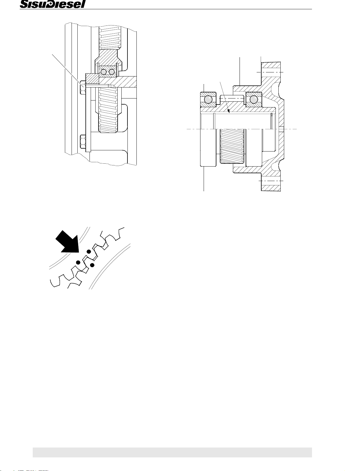
30 Nm
Timing Gear Assembly
E. Power take-off
In the engines is used a transmission that can be equipped with a PTO run from the camshaft gear. The PTO
can run e.g. a hydraulic pump.
A35x31
DIN 5482
m = 1,75
z = 18
2. If the compressor gear shaft has been removed, apply on its outer face Loctite 601 and hit the shaft in its position so that the shaft and gear housing back surfaces
are at the same level. Fit the bearing and the gear so
that the groove of the bearing inside ring comes outwards. Remember the lock rings! Fit the retaining ring
and tighten the screws to 30 Nm.
3. Note when assembling the camshaft, the timing mark
that differs from the other engines.
Note! Use molybdenite-sulphide (MoS2) ball bearing
grease (NLGI 2) for the grooves of the hydraulic pump
shaft and the coupling sleeve.
9 65
Page 67
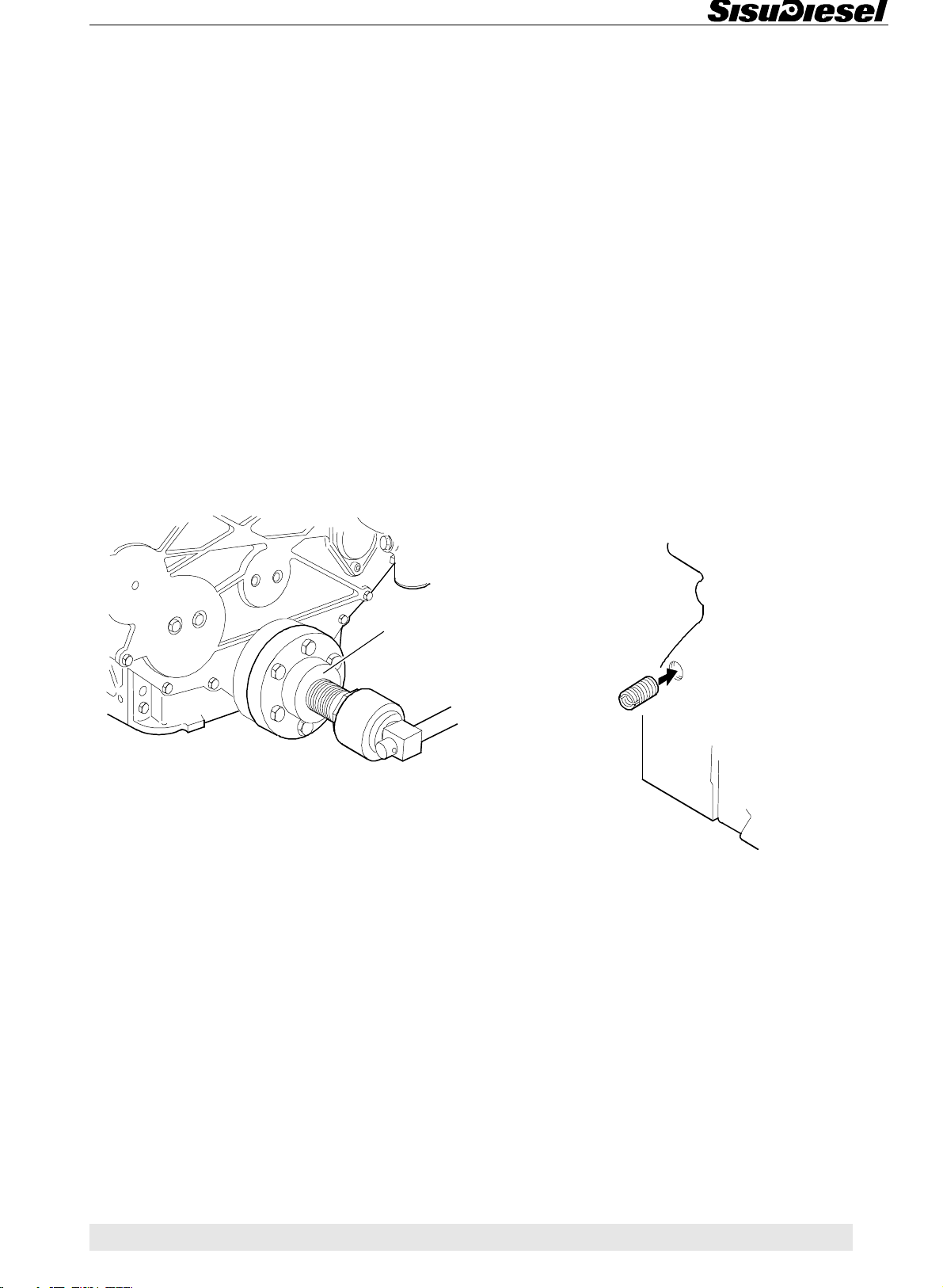
Timing Gear Assembly
9. TIMING GEAR ASSEMBLY
84-engines
A. Removing timing gear casing
As the timing gear casing bottom face forms a part of
the mating face for the oil sump gasket, the casing cannot be removed without first removing the oil sump.
1. Drain the engine oil and remove the oil sump.
2. Remove the radiator, fan, alternator, belt tensioning
and belt (if not removed earlier). If the engine is equipped with an air compressor or air conditioner, it has to
be removed.
3. Remove the crankshaft belt pulley and the vibration
damper.
Note! When removing the hub piece from the crankshaft front end mark the correct position of the hub.
7. Unscrew the idler gear screws and remove the idler
gear (broad timing gear casing).
8. Extract the camshaft.
Note! If the cylinder head and valve mechanism have
not been removed, the tappets must be prevented from
falling down, see instruction 4 B.
9. Remove the timing gear casing. Ensure that no sealing surfaces are damaged.
10. Remove the crankshaft front seal ring from the front
casing cover and clean all parts removed.
B. Fitting timing gear casing
The position of the timing gear casing and cover is determined by two tension pins. Therefore centring should
not be undertaken in connection with fitting. However,
the backlash between the different gears should be
checked. Casing and covers that are delivered as spare
parts also have holes for the tension pins already machined.
9104 53300
4. Loosen the crankshaft nut about two turns (special
tool 9024 55800). Fit extractor 9104 53300 and extract
the crankshaft hub. Take off the extractor, open the nut
and remove the hub.
Note! Do not remove the nut completely first. The
hub will be dashed dangerously when it is loosen.
5. Remove the cooling pump, observe the retaining screws on the injection pump side. Remove the timing
gear casing cover.
6. Remove the injection pump. See instruction 13 C.
Note! If the timing gear casing is not to be changed, the
injection pump can remain in place. In which case disconnect all leads and pipes from the pump. (Bosch P injection pump, loosen bottom mounting from the pump.)
1. Screw in the thread piece M14/M8 to the cylinder
block (narrow timing gear casing). Fit the casing with a
new gasket against the cylinder block. Hit in the tension
pins with drift 9025 98700. Tighten screws and nuts.
2. Fit the injection pump and its gear wheel (if removed).
3. Lubricate the camshaft bearings and insert the shaft
in the cylinder block. Release the push rods and tappets
if they have been suspended.
66 9
Page 68
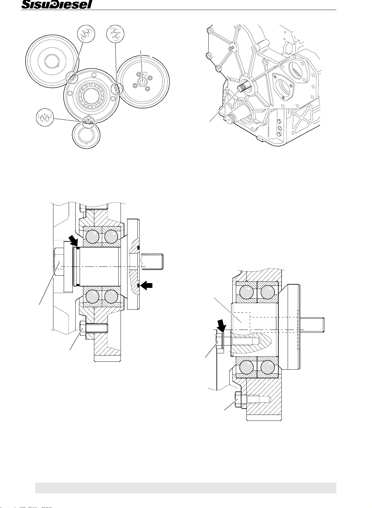
Timing Gear Assembly
Do not open!
9104 34600
Position of the timing marks.
Narrow timing gear casing
With the broad timing gear casing skip to the point 8.
180 Nm
5. Fit the guide pin 9104 34600 instead of the idler gear
bolt. Fit the camshaft axial controller in the cover (apply
sealing compound to the thread) and fit the cover. Hit in
the tension pins.
Note! If the crankshaft oil throwing ring is removed, fit it
(drift 9103 94900) before fitting the cover.
6. Tighten the cover screws. Remove the guide pin, fit
the idler gear shim and tighten the screw 180 Nm.
7. Skip to the point 12.
Broad timing gear casing
180 Nm
22 Nm
4. Assemble the idler gear as in picture. Place the o-ring
between the shaft and the cylinder block and fit the idler
gear in its place. Note the correct position of the timing
marks. Place an o-ring also in the shaft front end.
9 67
22 Nm
22 Nm
8. Assemble the idler gears as in picture. Fit the big idler
gear in its position. Note the position of the timing
marks. Fit also the small idler gear.
Page 69
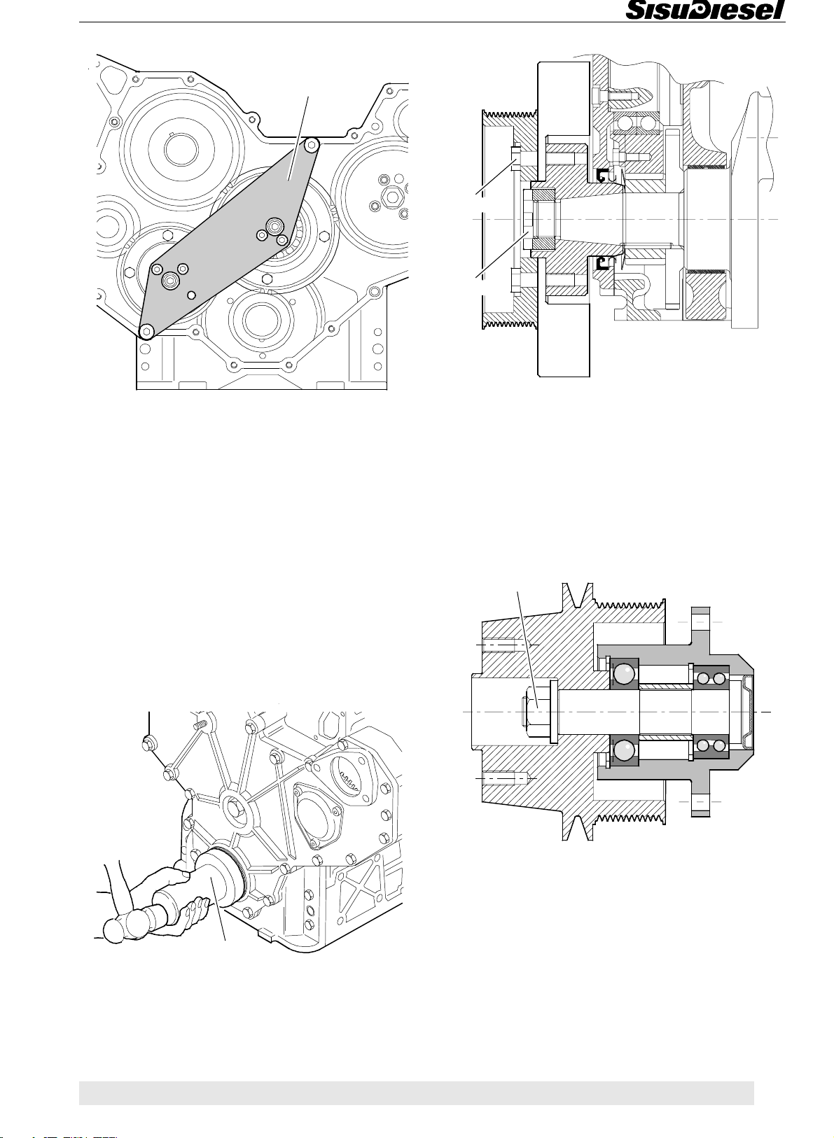
Timing Gear Assembly
9104 05400
9. Tighten the guide bolts in the guide unit frame and
position the unit on the idler gears as in picture (guide
bolts in the idler gear shaft holes and housing holes).
Tighten the idler gear bolts through the guide unit holes,
tighten 180 Nm. Remove the guide unit.
80 Nm
1000 Nm
13. Lubricate both the seal and sealing surfaces and fit
the crankshaft hub. Lubricate the crankshaft nut threads
and tighten the nut to 1000 Nm.
14. Fit the other removed parts.
10. Check the tooth backlash, which should be
0,05...0,25 mm.
11. Fit the drive unit shaft and camshaft axial controller
in the front cover (apply sealing compound to the
thread). Fit the cover and hit in the tension pins. Observe the idler gear shaft bolt seals. Fit the drive unit rear
bearing and cover.
Note! If the crankshaft oil throwing ring is removed, fit it
(drift 9103 94900) before fitting the cover.
9103 94600
12. Fit the protective plate into the bottom of the seal position and fit the crankshaft front seal with special tool
9103 94600.
C. Fan drive device
350 Nm
1. Assemble the drive device as the picture shows. Fit
inner bearing and circlip. Fill the bearing housing partially with heat resistant ball bearing grease (NLGI 2). Fit
the intermediate sleeve, outer bearing and circlip. Note
the position of the outer bearing as assembling.
2. Press the shaft into its position so that the pressing
force is not transmitted by the bearing balls.
68 9
Page 70
Timing Gear Assembly
3. Tap the blocking plug (if mounted) in its place with fitting drift 9025 87400.
4. Fit the belt pulley, washer and nut. Tighten the nut to
350 Nm.
9 69
Page 71
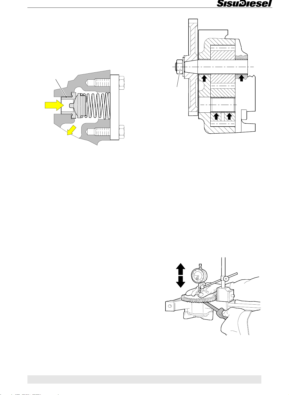
Lubrication System
10. LUBRICATION SYSTEM
A. Oil pressure regulating valve
If the engine lubricating oil pressure is insufficient or if it
varies, the regulating valve should be checked after first
checking the oil level.
Loctite 638
1. Remove the cover and the spring with valve plate.
2. Clean the parts and check that the sealing surfaces
are undamaged. Damaged parts should be changed.
Scrape off any remains of the gasket.
Note! There are two types of the spring.
60 Nm
7. On the 66-, 74- and 84-engines the bearing points
are provided with separate bearing bushings. If you
change the bushings, machine them to dimension of
18,000...18,018 mm after fitting.
C. Assembling and fitting lubricating oil pump
3. Apply locking fluid (e.g. Loctite 638) onto outside of
the valve seat. Tap the new valve seat in the cylinder
block using a suitable drift. Place the spring with valve
plate into the cylinder block and fit the cover with a new
gasket.
B. Removing and dismantling lubricating oil pump
1. Drain the engine oil and remove the oil sump.
2. Remove the oil pump suction and pressure pipe.
3. Remove the oil pump together with any shims between the pump and the cylinder block.
4. Remove the pump cover and the gasket. Remove the
gear on the dead axle.
5. Clamp the pump gear across the teeth in a vice fitted
with soft jaws, and loosen the drive gear nut. Knock the
gear wheel off by hitting the end of the shaft with a soft
hammer. Pull out the drive shaft-gear wheel.
6. Clean the parts and check for wear and other damage. See "Technical data", point "Oil pump". Change
damaged parts and all seals.
1. Fit the gear wheels in the pump body. Fit the cover
using a new gasket. Partly tighten the screws. Rotate
the pump shaft and tap the side of the cover lightly until
the position is reached where the shaft rotates most
freely. Tighten the screws and check that the shaft still
rotates freely.
2. Fit the drive gear onto the shaft. Apply locking fluid
(e.g. Loctite 242) onto the nut threads and tighten the
nut to 60 Nm. Remember the washer under the nut.
3. Fasten the oil pump in a vice and check the end float
between gear and pump housing. The clearance which
should be 0,03...0,11 mm, is adjusted by the number of
gaskets between the cover and body.
70 10
10
Page 72
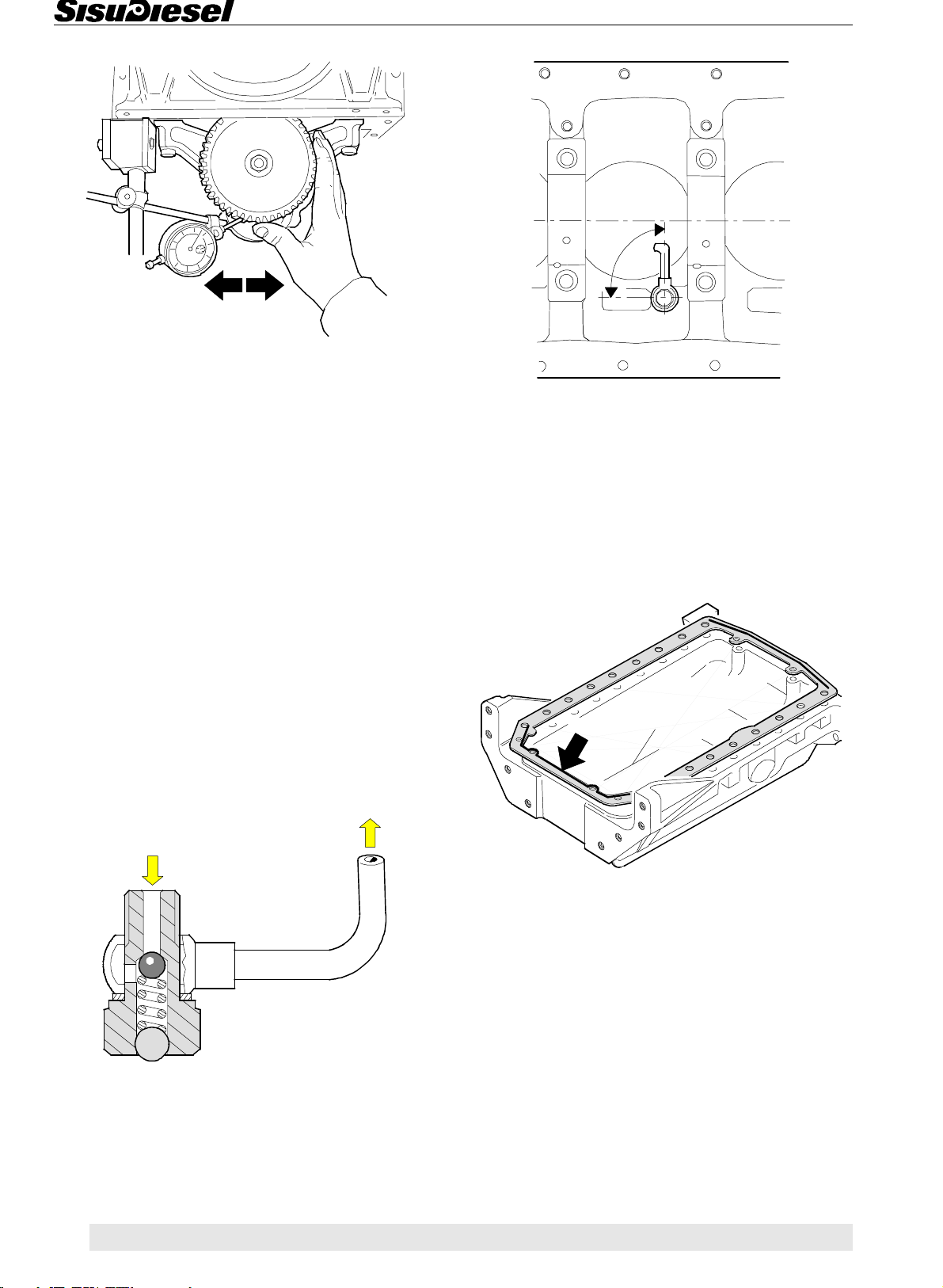
Lubrication System
4. Fit the pump and check the tooth backlash against
the crankshaft gear. The clearance, which should be
0,05...0,25 mm, is adjusted with shims between the
pump body and the cylinder block (shim 0,2 mm, order
no. 8360 07871). One shim increases/decreases the
backlash about 0,07 mm.
Note! When measuring the tooth backlash, the engine
should be the correct way up as the crankshaft bearing
clearance affects the tooth backlash.
5. Connect suction and pressure pipes together with
new seals.
90°
2. Fit the nozzle pipe at the angle of 90° to the centre
line of the crankshaft according to the above picture.
Tighten the valve to 30 Nm. Ensure that the pipe does
not touch the pistons or connecting rods when the engine is running.
E. Fitting oil sump gasket
6. Fit the oil sump and fill in the lubrication oil.
D. Piston cooling nozzles
The engines with high output are equipped with the piston cooling nozzles. The cooling nozzles can be removed after removing the oil sump. The nozzles have a
ball valve with an opening pressure of 3±0,25 bar.
1. Change the valve if necessary. Detach the valve from
the engine and remove the nozzle pipe. Fit a new valve.
TOP
Fit the oil sump gasket with the silicone stripes against
the cylinder block (self carrying and casted oil sumps).
F. Lubricating oil cooler
33-, 44,- 66- and 74-engines
Some engines are equipped with a oil cooler, positioned
in between the oil filter and the cylinder block.
1. The engine coolant should be drained before removing the lubricating oil cooler.
10 71
Page 73
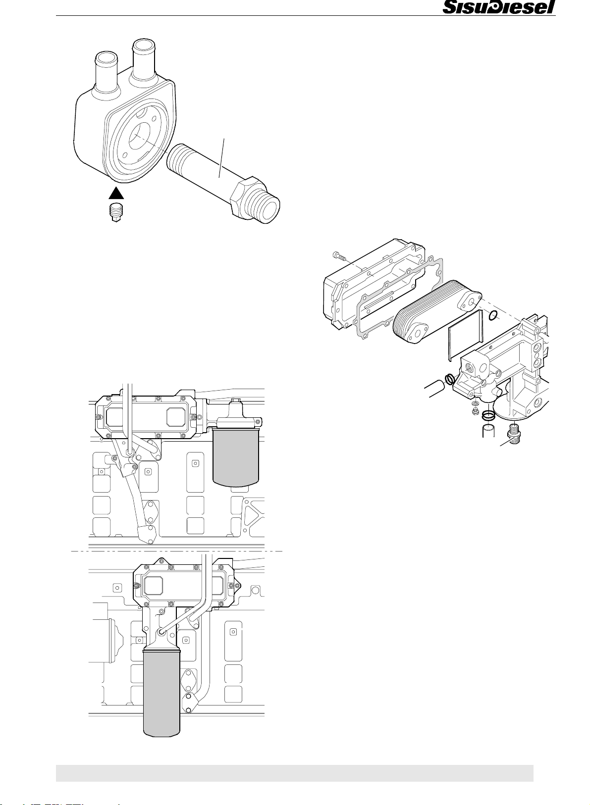
Lubrication System
60 Nm
2. Fit new sealing rings. Fit the cooler with draining plug
turned downwards. Connect coolant pipes in the correct
way.
3. Apply locking fluid (e.g. Loctite 242) to the nipple (the
thread which attaches to the cylinder block) and tighten
it to a torque of 60 Nm.
To remove
1. Open the coolant drain plug under the oil cooler and
drain the coolant into a suitable container. Remove the
pipe going into the thermostat housing.
2. Remove the turbo oil pipes and the oil pressure pipe
from the cylinder block. Remove the oil filter. Drain the
oil into a container.
3. Remove the oil cooler from the engine. Open the cooler housing and remove the guide plate. Unscrew the
cell screws and remove cell from the body. Clean the all
parts.
Fitting oil cooler
84-engines
Practically there are two different oil coolers, the difference being position of the oil filter, see picture below.
8368 59108
50 Nm
1. Assemble the oil cooler using new gaskets. Fit the
cell to the body. The oil side can be pressure tested before fitting the housing. Test pressure is 5 bar.
2. Push the guide plate between the cell and the body
and fit the housing. If needed now can the water side be
pressure tested, test pressure 5 bar.
3. Assemble the oil cooler to the engine and assemble
oil- and coolant pipes. Replace the oil filter.
4. Fill the coolant system. Start the engine and check for
leakages.
8363 36459
72 10
Page 74
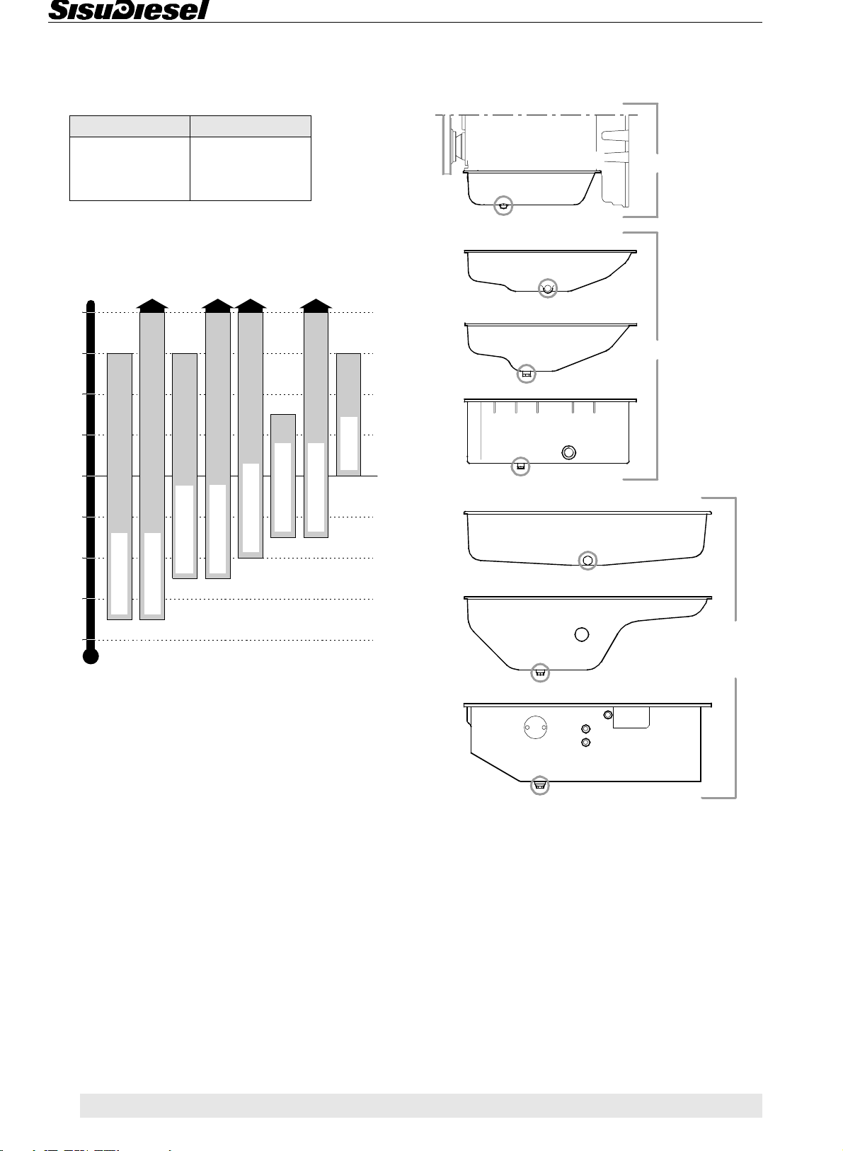
Lubrication System
G. Lubricating oil quality requirements
Use lubricating oils fulfilling following quality grades.
API -grade ASEA -grade
CG-4 E3-96
CH-4 E4-98
E5-99
Select viscosity grade from table below corresponding
to outside temperature.
°C
+40
+30
+20
+10
H. Oil capacities
min. 6,0 max. 7,5 dm
min. 8,0 max. 10,0 dm
min. 9,5 max. 11,5 dm
min. 25,5 max. 29,0 dm
3
3
3
33
44
3
-10
-20
-30
-40
0
min. 26,0 max. 30,5 dm
SAE 20W-20
SAE 20W-40
3
SAE 15W-40
SAE 30
SAE 10W-40
SAE 10W-30
min. 21,5 max. 25,5 dm
SAE 5W-30
SAE 5W-40
3
66
74
84
min. 42,0 max. 46,5 dm
1 dm3 = 1 litres
3
10 73
Page 75
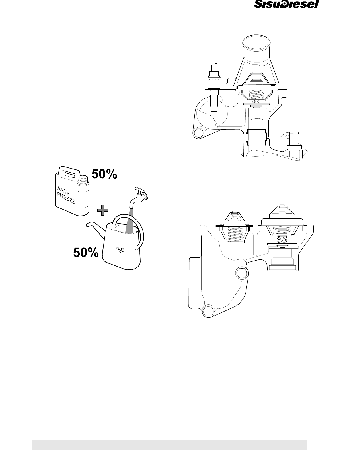
Cooling System
11. COOLING SYSTEM
A. Quality requirements of coolant
The coolant used must meet the demands of standard
ASTM D 3306 or BS 6580:1992.
• The cooling mixture must consist 40...60 % of ethylene/propylene-glycol based antifreeze and
water. The best proportion is 50 % of antifreeze
liquid and 50 % of water.
• The water used must be mechanically clean and
not too acid (e.g. swamp water) or too hard (calciferous well water).
• Check periodically the proportion (the frostproof)
of the coolant. Change the coolant every two
years.
33-, 44- and 66-engines
The thermostat is of a two-way type. Its opening temperature is 83°C.
Note! Never use only water as coolant!
B. Thermostat
Check the function of the thermostat as follows:
• Lower the thermostat into a vessel of boiling water
so that the thermostat does not touch the sides or
bottom.
• Opening must begin under 20 seconds.
• The thermostat must be fully open under 50 sec-
onds. Stroke, see "Technical data" point "Ther-
mostat".
66- and 74-engines
Some 66- and 74-engines have two separate thermostats. These are separated from the type of the single
thermostat and they are not interchangeable. To these
engine there are no separate winter thermostats.
74 11
11
Page 76
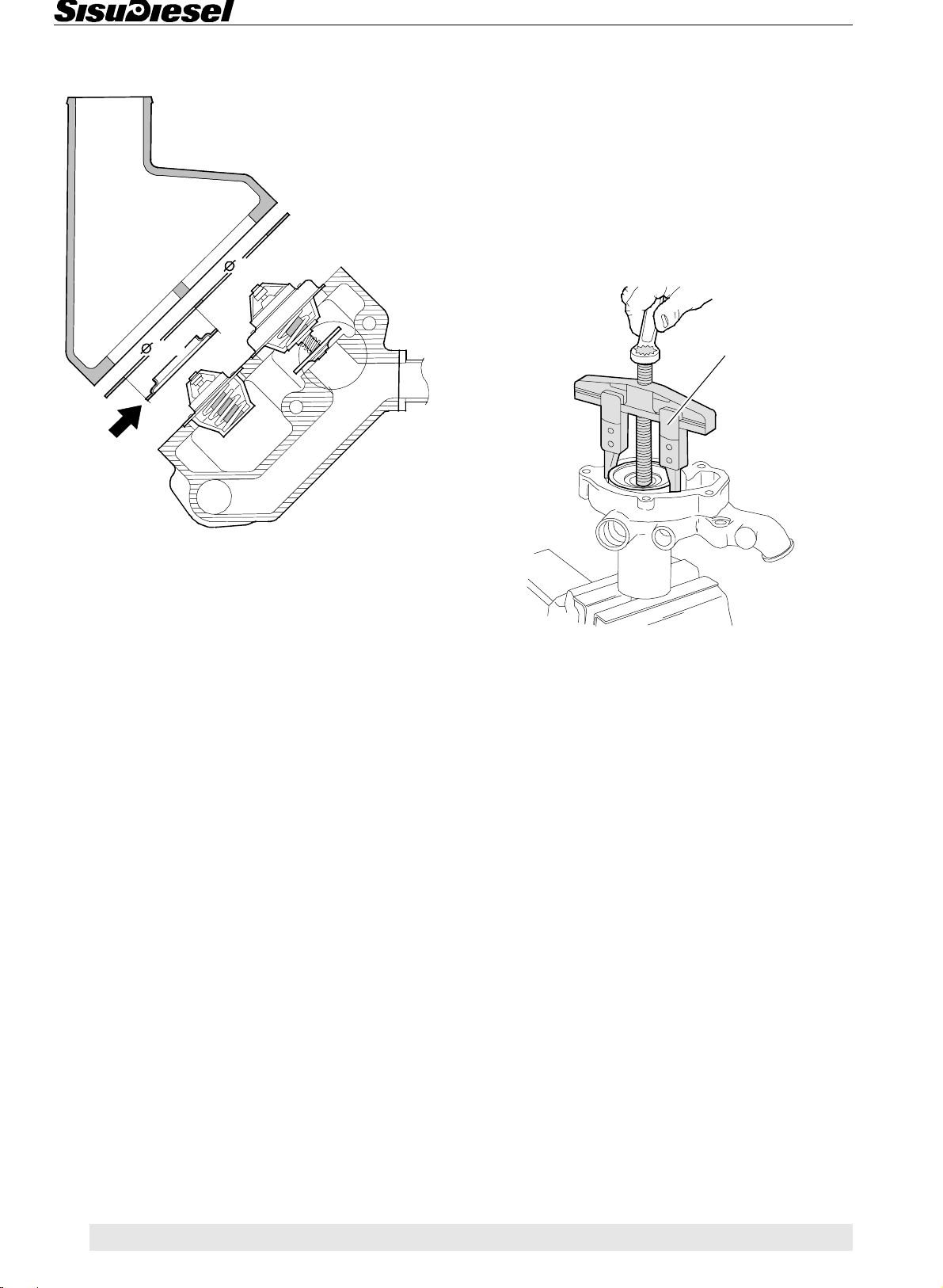
Cooling System
84-engines
67,5
62,0
C. Reconditioning coolant pump
33-, 44-, 66- and 74-engines
1. Drain the coolant. Remove the thermostat housing,
fan and the v-belt.
2. Remove the coolant pump. Detach the pump rear
plate and clean the sealing surfaces.
3. Unscrew the belt pulley fixing nut/screw and remove
the belt pulley.
9104 27700
84-engines have two separate thermostats. The smaller, single-acting thermostat opens at 79°C and the other, double-acting type, at 83°C. In 84-engines there
are no separate winter thermostats.
To remove
1. Drain the cooling system so that the coolant level is
below the thermostats position and disconnect the top
hose from the water outlet cover.
2. Remove the outlet cover and the thermostats. Clean
the sealing surfaces.
To replace
1. Put the thermostats in position in the housing. Fit a
new gasket and the outlet cover. For guiding you can
use M8 studs (2 pcs). Observe the plate (if mounted)
that comes on top of the smaller thermostat. Fit the gasket so that the bigger hole is on the same side as the
plate.
2. Connect the top hose and fill the cooling system.
4. Remove the impeller on the shaft with puller 9104
27700 (33- and 44-engines) or 9101 93200 (66- and 74engines).
5. Remove the circlip in the pump body. Press the shaft
together with bearings in the direction of the fan. Use
e.g. a hydraulic press. Support the pump body so that
the bearings have enough space for releasing.
6. Tap out water and shaft seals using a drift. Clean the
parts and inspect their condition. Replace faulty or worn
parts with new ones.
Note! If the pump bearings have to be changed, use a
reconditioning kit. This kit also contains all seals (see
Parts Catalogue).
7. Drive in the new shaft seal in the housing using a suitable drift. Put the bearings and the intermediate sleeve
onto the shaft. Grease bearings with heat-resistant ball
bearing grease (NLGI 2). Fit the shaft and the bearings
in such a way that the pressing force is not transmitted
by the bearing balls. Fit the circlip for the bearing.
11 75
Page 77
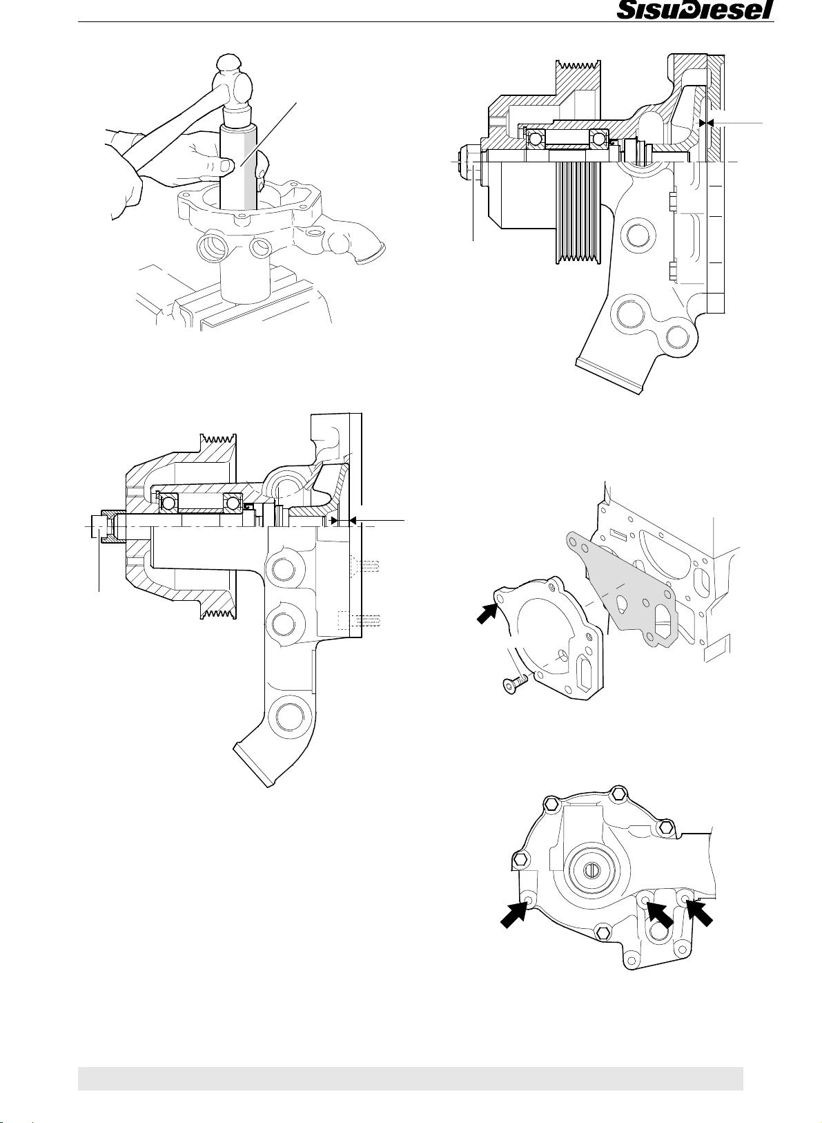
Cooling System
9051 79300
8. Fit the water seal with drift 9051 79300. Use as a
"lubricating liquid" coolant between the shaft and the
seal.
0,8...1,2
120 Nm
9,0...9,3
80 Nm
9. Press the impeller into position while, at the same time, supporting the shaft at the other end. The mounting
depth of the impeller is in 33- and 44-engines
9,0...9,3 mm (see picture above). Make sure that the
shaft can rotate freely. Fit the belt pulley and tighten its
attaching screw to a torque of 80 Nm. Note specially the
left hand thread of belt pulley attaching screw.
The mounting depth of the impeller is in 66- and 74-engines 0,8...1,2 mm (see picture above). Make sure that
the shaft can rotate freely. Fit the belt pulley and tighten
its attaching nut to a torque of 120 Nm.
Loctite 572
10. Fit the rear plate to the cylinder block using a new
seal. Use guide pin (Ø8 mm) in the hole shown with arrow in the picture above. Apply sealing compound to the
thread of screw.
On 66- and 74-engines, fit the rear plate to the pump
using a new seal. Use guide pins (Ø8,5 mm) in the holes shown with arrows in the picture above.
76 11
Page 78
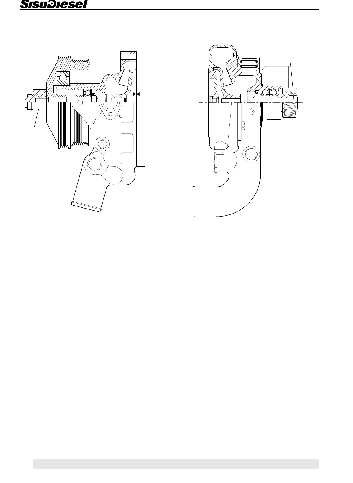
Cooling System
D. Coolant pumps with heavy duty bearings
66- and 74-engines
0,8...1,2
120 Nm
Note! If the pump bearings have to be changed, use a
pump repair kit. This kit also contains all seals (see
Parts Catalogue).
180 Nm
Some versions of 66- and 74-engines have a heavy
duty bearings in the coolant pump. The reconditioning
of this pump is done according to the instruction 11 C.
Note specially the position of the front bearing as assembling.
E. Reconditioning the coolant pump
84-engines
1. Drain the coolant. Disconnect the hose at the inlet
connection of the coolant pump. Loosen the coolant pipes from the coolant pump.
2. Release the three screws which retain the coolant
pump to the cover of the timing case-from the rear. Remove the coolant pump.
3. Unscrew the gear fixing nut and remove the gear. Remove the pump housing from the pump body.
4. Remove the circlip in the pump body. Press the shaft
together with bearings in the direction of the gear.
6. Tap the new shaft seal in the body using a drift 9103
41000. Grease bearings with heat resistant ball bearing
grease (NLGI 2). Press in the bearings and fit the circlip.
7. Fit the shaft in such a way that the pressing force is
not transmitted by the bearing balls.
8. Hit the water seal into its position with tool 9103
41100. Press the impeller to its position (towards the
shaft shoulder) supporting the shaft from the other end.
Make sure that the shaft can rotate freely.
9. Fit the gear on the shaft and tighten the nut to
180 Nm.
10. Fit the pump housing using new gasket.
11. Fit the pump using new o-ring.
Note! If both coolant pump and injection pump are removed, fit the coolant pump first (one fitting screw can
not be fitted as injection pump is in position).
5. Tap out the water seal and shaft seal using a drift.
Remove o-ring seals and clean the parts and inspect
their condition. Replace faulty or worn parts with new
ones.
11 77
Page 79
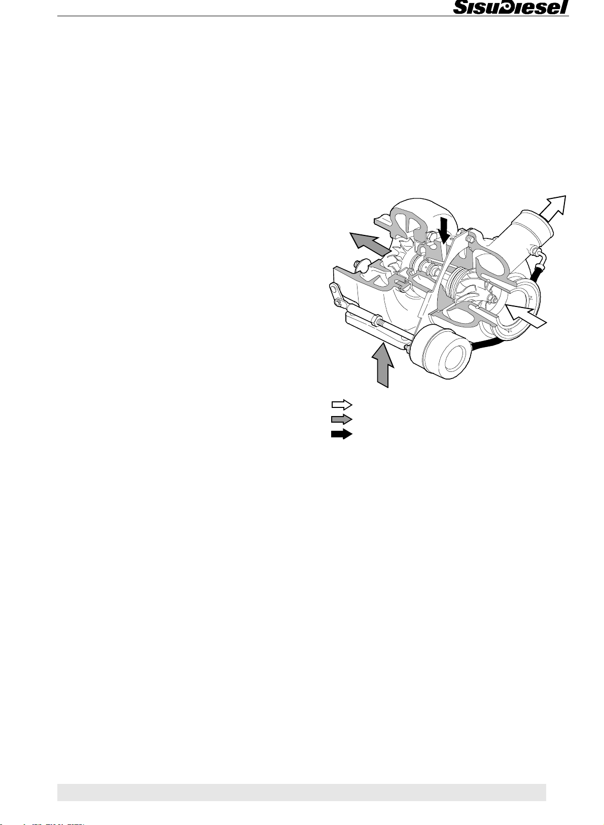
Inlet and Exhaust System
12. INLET AND EXHAUST SYSTEM
An engine that is equipped with a turbocharger is a great deal more sensitive to disturbances and impurities in
the inlet and exhaust systems than a naturally aspirated
engine. Therefore special attention should be given to
the whole inlet and exhaust system.
A. Checking air cleaner
The engine performance and length of service life depend to a great extent on the state of the air cleaner. A
defective air cleaner allows impurities to pass through,
which in time damage the turbocharger and the engine.
A blocked air cleaner lowers the engine output and also
causes oil leakage through the sealing ring on the turbocharger shaft.
Note! The safety filter inside the main filter should not
be removed unnecessarily, for checking or cleaning.
The safety filter must not be cleaned, but should be
changed when necessary.
5. Remove the manifold if necessary. Clean the sealing
surfaces and remove any carbon deposits. Check that
the sealing surfaces are flat. If the fastening flanges are
twisted or there are scratches on the sealing surfaces,
machine the flanges or renew the exhaust manifold.
6. Ensure that no loose objects or impurities have entered the exhaust pipe or the silencer. Any such loose objects or impurities can increase the back pressure for
the exhaust gases from the turbine wheel.
B. Checking inlet and exhaust pipes
Important! Leaks in the inlet or exhaust system mar-
kedly lower the effect of the turbocharger. Because of
the pressure, even small leaks in the manifold or in the
turbine inlet contact flange quickly increase in size. For
this reason all leaks must be dealt with immediately.
1. Inspect the pipes and sealing surfaces between the
air cleaner and the turbocharger, as well as between
the turbocharger and the intake manifold. If the intake
manifold is dusty on the inside, there is a leak in either
the air cleaner or the inlet pipes. Remedy the leak.
2. Clean the intake manifold sealing surface. Check that
the sealing surface is flat using a straight ruler. If the
surface is not flat or it has scratches, machine or renew
the intake manifold. On 66-, 74- and 84-engines ensure
that the cylinder heads are parallel.
3. Fit a new gasket and fasten the intake manifold. Tighten the manifold fixing screws to a torque of 30 Nm.
Fasten the air pipes carefully.
4. Check that the exhaust manifold is air tight. Tighten
the nuts to 50 Nm and inspect for any damage (cracks,
deformation, corrosion etc.). Check also the connection
between the turbocharger and the exhaust manifold.
Inlet air
Exhaust gases
Lubrication oil
C. Checking turbocharger
If a fault is suspected in the turbocharger it can be located in the following way:
1. Visually inspect the turbine and compressor wheels.
The vanes must not show any signs of damage, deformation or wear caused by foreign objects.
2. Investigate any oil leaks through the sealing rings on
the shaft in the turbine and compressor housing.
Note! At low idling there is always a certain amount of
oil leakage on the compressor side. However, this
should not cause too much concern unless the oil consumption is too great.
78 12
12
Page 80
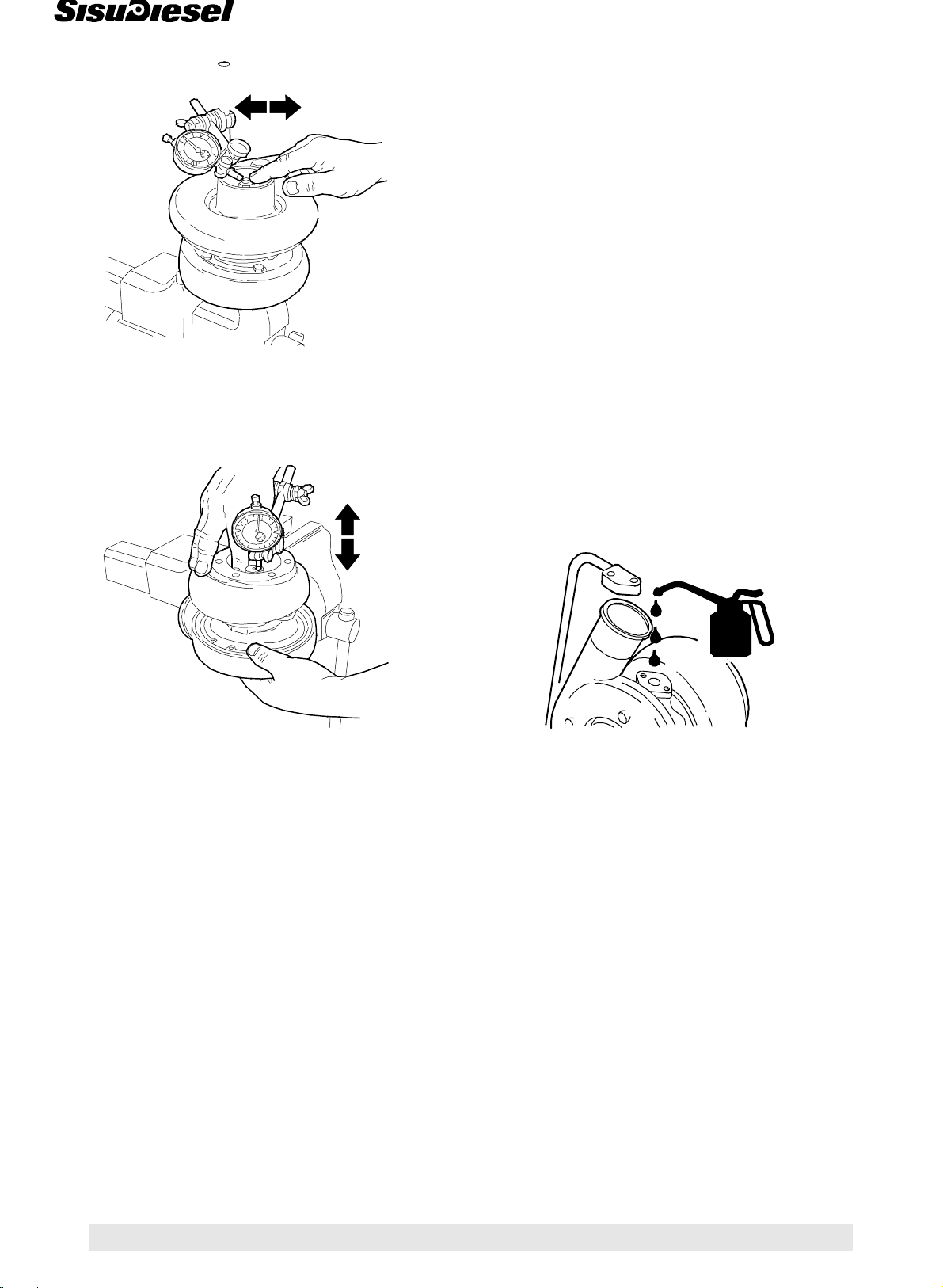
Inlet and Exhaust System
D. Fitting turbocharger
Locate the cause of the defects on the turbocharger.
Remedy the fault before fitting the new turbocharger.
In order for the turbocharger to work satisfactorily, it is
important that the engine oil is in good condition. Likewise the oil should be to the correct quality specification. The air filter and oil filter should be serviced
according to the Instruction Manual specification.
The setting of the injection system critically affects the
function of the turbocharger. The injection system
should be adjusted according to the manufacturers
instructions.
3. Check the turbine shaft running clearance. Place the
stylus of a dial gauge against the shaft and move the
shaft sideways. refer to the clearance given in the specifications. See "Technical data" point "Turbochar-
ger".
4. Check the shaft end float. Place the stylus of the dial
gauge against the end of the shaft and move the shaft
axially. Refer to the clearance given in the specifications. See "Technical data" point "Turbocharger".
1. Check the tightness of the intake and exhaust manifolds, and that they are securely fastened. Ensure that
there are no loose carbon or rust particles, or other foreign objects in the manifolds.
2. Connect the turbocharger to the exhaust manifold
and tighten down using a new gasket.
3. Connect the inlet pipe and the exhaust pipe on the
turbo.
4. Pour abt. 0,1 litres of pure engine oil into the bearing
housing before attaching the pressure oil pipe. This is
very important in order to ensure that the turbocharger
is lubricated at the time of starting.
If any defects or wear are confirmed, the turbocharger
should be reconditioned.
If the engine does not work correctly and the turbocharger is not defective or too worn, the fault could be traced
to one of the following items:
• Blocked air filter.
• Leakage in the inlet or exhaust systems. Leaking
flange seal.
• Defective injection pump or EEM 2 control unit.
• Defective or wrongly adjusted injectors.
• Low fuel pressure (e.g. blocked fuel filter).
• Low compression, wrong valve clearance.
12 79
5. Connect the pressure and return oil pipes. Use a new
seal. Check that there are no tensions in the pipes when
tightening.
6. Start the engine and check that there are no leaks.
Page 81
Fuel System
13. FUEL SYSTEM
Fortius series engine fulfils the emission requirements set by authorities (EU97/68/EC Stage 2 and EPA 40 CFR 89
Tier 2). The manufacturer guarantees that all engines of this type are equivalent to the engine that is officially approved. This must be noticed especially when performing periodical maintenance, follow carefully the service
schedule. Any adjusting and repair work for the injection system or the engine control unit can only be made by a
representative authorized by Sisu Diesel Inc. When performing any service or repair work use only original SisuDiesel spare parts. Inadequate or delayed service and the use of other than original SisuDiesel spare parts invalidates
the responsibility of Sisu Diesel Inc. on the fulfilment of the emission requirements.
Note! This manual gives only general instructions for repair and service measures related to the fuel system. This
applies particularly to changing of the injection pump which can be done only by a specially trained person who has
the necessary special tools and gauges. All service and repair work related to the fuel system requires special care
and cleanliness!
Injectors
Order no. Manufacturer Type Nozzle no. Opening pres-
sure bar
8368 54791 Stanadyne M 8368 54792 270
8368 54940 Stanadyne M 8368 54941 270
8368 54929 Stanadyne M 8368 54930 270
8368 54992 Stanadyne M 8368 54991 270
8366 59808 Stanadyne M 8366 59902 270
8367 64613 Stanadyne M 8367 64614 270
*)Value to be used when adjusting the opening pressure of a new or used injector.
Adjusting plate for injector (1,00…2,00 mm) order no. 8368 62000…8368 62020.
Tightening torques
Injector attaching nuts (on studs) ................................................. 15 Nm
Injector nozzle sleeve...................................................................60 Nm
Delivery pipe attaching nut to injector..........................................25 Nm
+8
+8
+8
+8
+8
+8
Setting pressure* bar
278 876
278 301
278 234
278 625
278 358
278 927
Code
80 13
13
Page 82
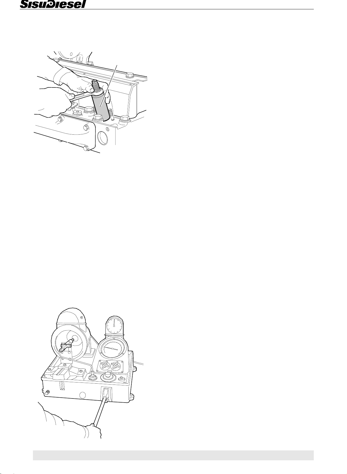
Fuel System
A. Removing injectors
1. Clean the injectors and the area around them. Disconnect the delivery pipes and the leak-off pipes.
9051 71300
2. Remove the injector attaching nuts and remove the
injector from the cylinder head. Fit protective plugs to all
connections. If the injector does not rise by hand, use
puller 9051 71300.
3. Remove the sealing washers from the bottom of the
injector location in the cylinder head if they do no come
out with the injector.
2. Secure the injector in a test bench and check the following:
• injector opening pressure
• the properties of the chattering (creaking) sound
and the form of the spray pattern
• sealing of nozzle valve against its seat.
Opening pressure
Pump a few times to fill the injector. Increase the
pressure in the injector until the chattering (creaking)
sound becomes audible. Read off the opening pressure
of the injector. If the opening pressure deviates from the
given value, the injector should be taken apart and
checked.
Adjustment is achieved by changing the shim. The
thickness of the shims varies from 1,00...1,90 mm and
they are available in increments of 0,05 mm. A thicker
shim will raise the opening pressure while a thinner one
lowers it. A difference in shim thickness of 0,05 mm
changes the opening pressure by approx. 5,0 bar. As
the opening pressure of the injector drops slightly after
adjustment, the opening pressure should be set to approximately 10 bar above the value given in the specifications. This value applies both to new and used
injector.
B. Inspecting injectors
Note! When pressure testing the injectors, it is important to avoid the nozzle end as the fuel jetting
out easily penetrates the skin. Also bear in mind
that the fuel "mist" is dangerous to inhale.
1. Clean the injector with cleaning fluid and a soft brush.
The carbon deposits must not be knocked off or removed in any other way which may damage the nozzle.
Chattering sound properties
Testing with a hand powered pump does not create the
same circumstances as when the injector is fitted in the
engine. Only with new nozzles are the test results reliable. With used nozzles, there is no chattering (creaking) sound when the tester is pumped at a certain rate.
This has to do with the design of the nozzles.
However, with a rapid pumping on the tester handle, it
should be possible to hear the chattering (creaking)
sound or/and see a mist of the fuel jetting out.
Tightness of nozzle
Press down the tester pump lever until the pressure rises to approx. 20 bar below the adjusting value. Maintain this pressure for approximately 10 seconds and
check whether drops of fuel are formed on the point of
the nozzle. If the injector leaks, it should be cleaned or
the nozzle should be changed.
13 81
Page 83
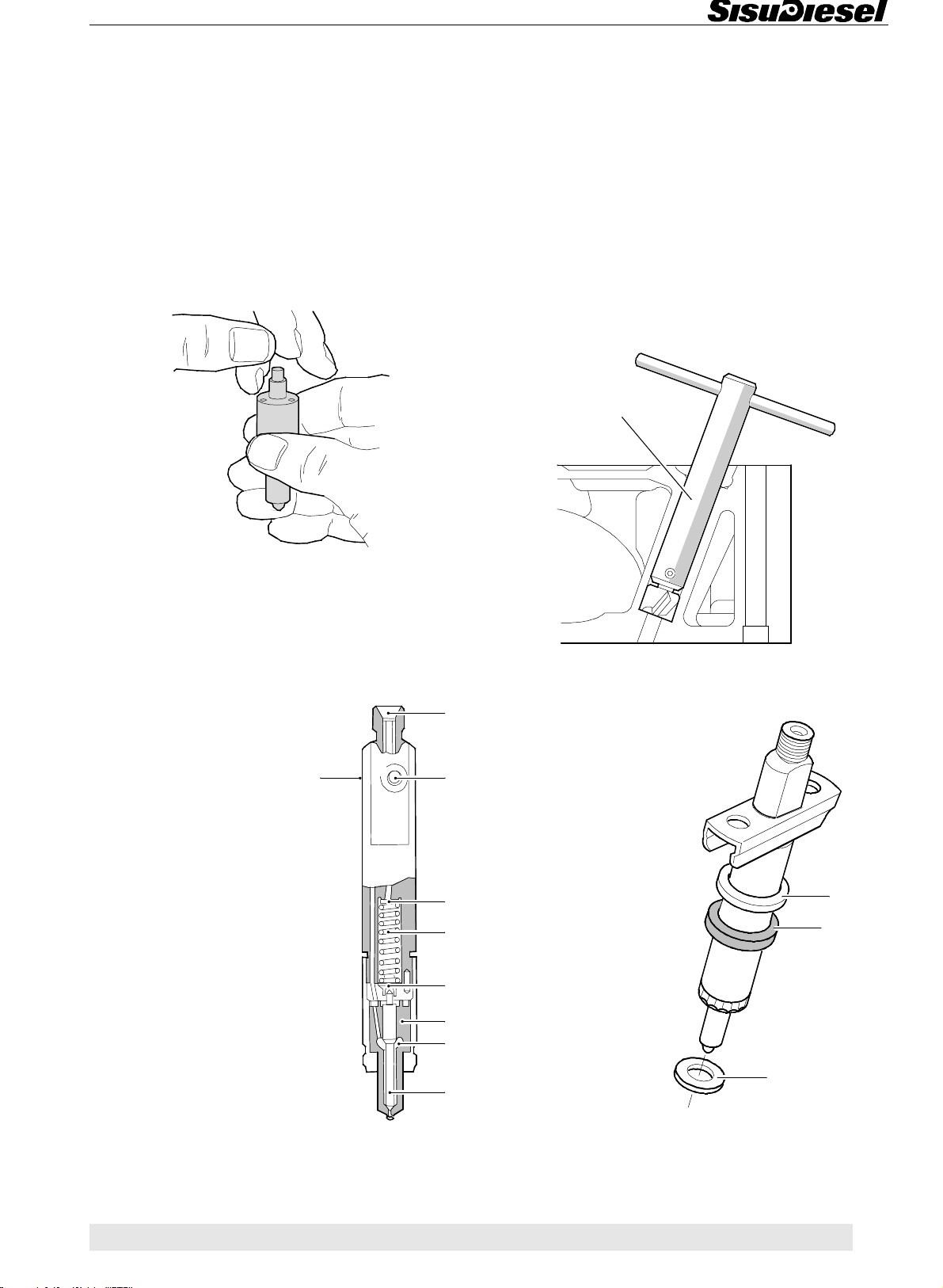
Fuel System
C. Reconditioning injectors
1. Secure the injector in a suitable way.
2. Unscrew the nozzle cap nut. Remove the nozzle and
the parts inside the holder.
3. Clean the nozzle in cleaning fluid both inside and outside.
4. Clean the nozzle holes with a suitable needle.
5. Test the movement of the nozzle valve as follows:
6. Before assembling, all parts should be carefully cleaned in clean fuel or testing fluid.
7. Put the same thickness of shim back as were fitted
earlier. Note possible adjustment of the opening
pressure. Assemble the rest of the injector. Note the position of the spring guide and the valve stop spacer.
8. Tighten the nozzle cap nut by hand and then to
60 Nm.
D. Fitting injector in engine
9101 66000
Rinse the parts thoroughly in fuel or testing fluid. Pull
the valve out of the nozzle body to 1/3rd of its length. If
the fit is correct, the valve should be able to slide down
in the nozzle body under its own weight. Turn the valve
slightly and repeat the test. Should the nozzle valve
bind slightly, it should be changed.
1
Injector
1. Fuel inlet
9
2
2. Leak-off pipe connection
3. Adjusting shim
4. Pressure spring
5. Pressure pin
6. Nozzle body
7. Pressure chamber
3
8. Injector needle
9. Number code
4
5
6
7
1. Clean the injector sealing surface in the cylinder
head. If necessary use a reamer 9101 66000.
1
1. Washer
2. Rubber ring
2
3. Sealing washer
3
8
2. Fit the injector in the cylinder head using a new sealing washer.
82 13
Page 84
Fuel System
Note! The spray pattern from the injector is not symmetrical on purpose. It is therefore important that the injector is fitted correctly in the cylinder head. The
connection for the leak-off line should be facing the valve mechanism.
3. Fit the attaching clamp and tighten the nuts evenly to
15 Nm.
4. Connect the leak-off line together with new sealing
washers and connect the delivery pipes.
Note! The screw studs in the cylinder head for the injectors should only be finger tight. If tools have to be used
the studs should be tightened only lightly.
Note! Make sure, that the injector is of a correct type.
Wrong injectors cause malfunctions and can damage
the engine.
E. Fitting delivery pipes
1. Check the state of the pipes. If there are kinks, damage by chafing, or if the tapered sealing end is damaged,
the pipes should be changed.
2. Fit the pipes without tension and check that they are
at right angles to the union. Tighten the delivery pipe attaching nuts to 25 Nm. Do not overtighten!
3. Fit the clamps for the pipes.
13 83
Page 85
Fuel System
Bosch VE rotary pump
Technical data
Injection pump
Type .............................................................................................Bosch VE rotary pump
Fitting position º BTDC (static):....................................................5º
Piston distance of the injection pump (in assembling) .................0,30 mm
Direction of rotation from the engine front.................................... Clockwise
Injection order:
- 33-engines .................................................................................1 - 2 - 3
- 44-engines .................................................................................1 - 2 - 4 - 3
- 66-engines .................................................................................1 - 5 - 3 - 6 - 2 - 4
Fuel system
Fuel ..............................................................................................The fuel must be according to norm EN 590
Fuel filters:
- Pre-filter .....................................................................................Stanadyne 30 µ, element no. 8368 66575
- Fuel filter .................................................................................... Stanadyne 5 µ, element no. 8368 66577
Fuel feed pump ............................................................................ Diaphragm pump, separate hand lever
Fuel feed pressure (static) ...........................................................0,48 bar
Fuel feed pressure min. (used pump) .......................................... 0,20 bar / max. rpm
Tightening torques
Injection pump retaining nuts M8 .................................................30 Nm
Injection pump gear retaining screws........................................... 35 Nm
Injection pump coupling flange retaining nut............................. 92,5 Nm
Delivery pipe attaching nut to pump.............................................25 Nm
84 13
Page 86
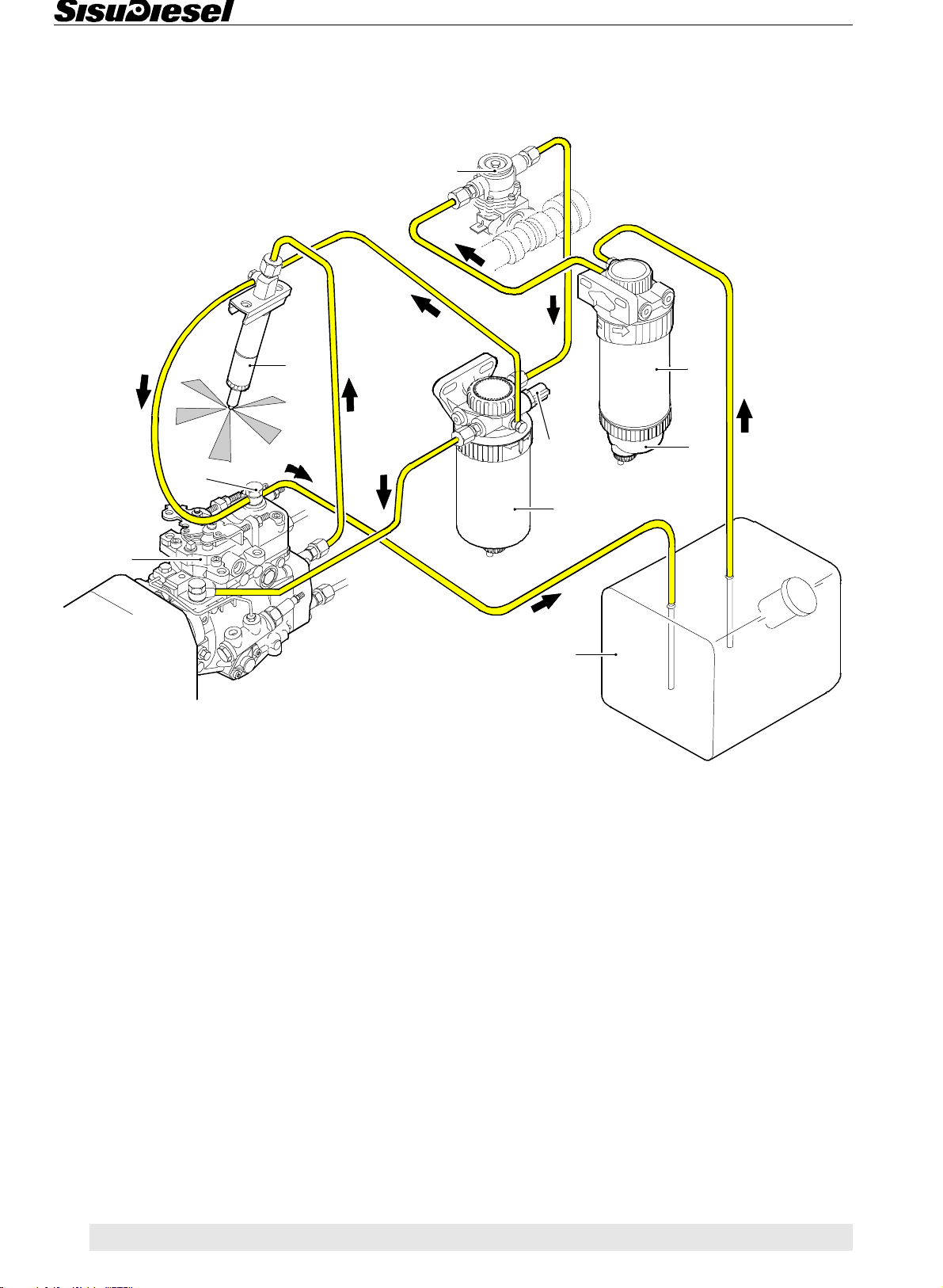
Fuel System
Fuel system, description
Some Fortius series engines are using a mechanically
controlled Bosch VE rotary injection pump.
4
7
9
8
5
6
1
Fuel system (injection pump Bosch VE)
1. Fuel tank 6. Injection pump
2. Pre-filter 7. Injector
3. Water separator (optional) 8. Overflow valve
4. Feed pump 9. Feed pressure sensor (0,05 - 0,2 bar)
5. Fuel filter
2
3
The fuel is pumped by feed pump from the tank via a
pre-filter, trough the filter to the injection pump. The injection pump forces the fuel into the injector that feeds
fuel into the combustion space in fine spray. Excess fuel
returns from the fuel injection pump through an overflow
valve to the fuel tank. The overflow pipe between filter
and injectors helps the automatic bleeding of the system.
13 85
The fuel system is equipped with a pressure sensor that
alarms before interference has developed. An option
the pre-filter can be equipped with a see-trough water
trap and with an electronic water in fuel sensor.
Page 87
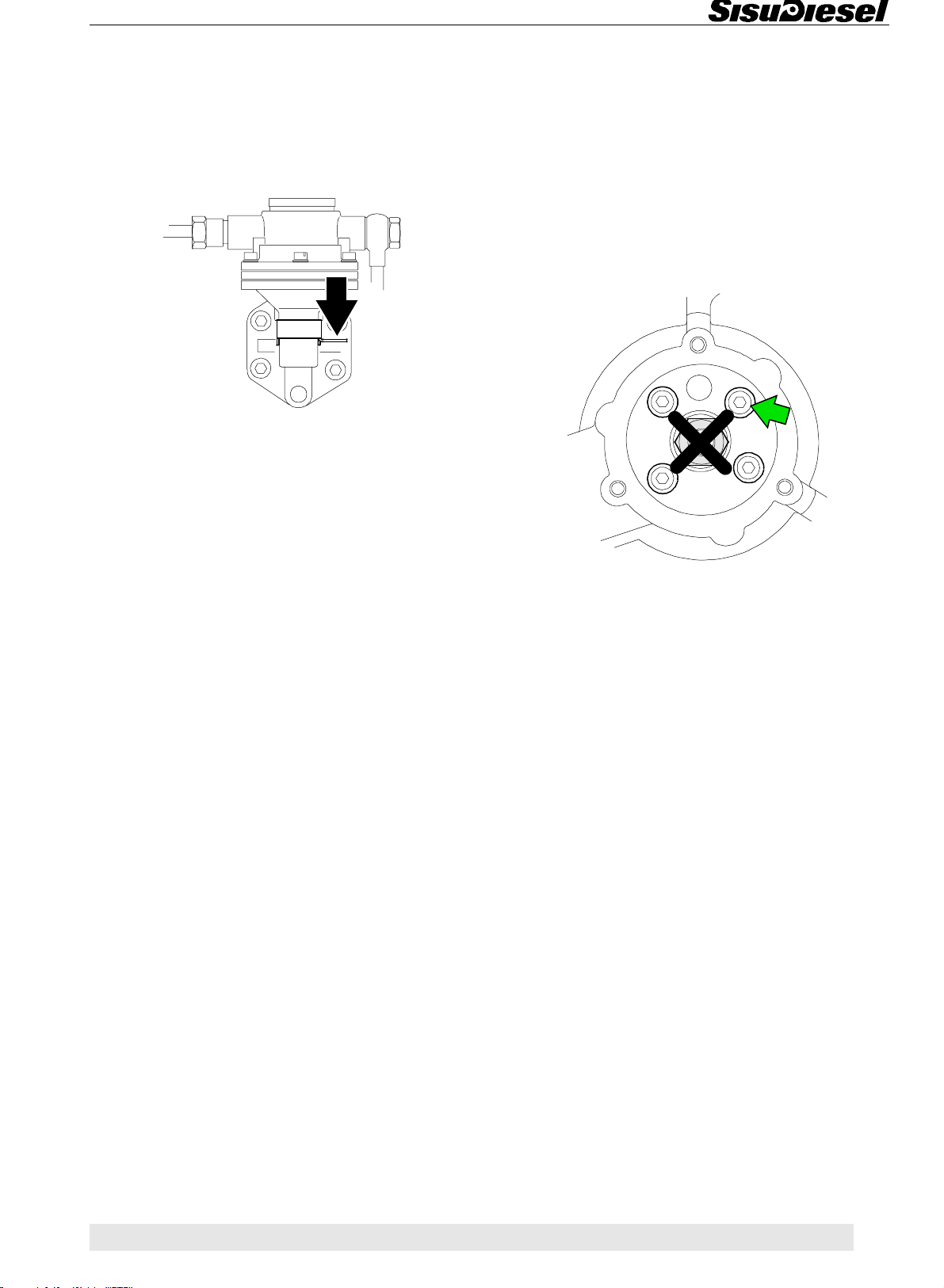
Fuel System
A. Bleeding the fuel system
Note! This fuel system bleeds automatically small
amounts of air bubbles from the filter and the pump
when the engine is running. However, bleed the system
always, when the fuel filters have been replaced or fuel
has run out during driving.
1. Pump by hand the fuel feed pump lever. If the pumping seems to be ineffective, turn the engine a little so
that the camshaft cam is not at the feed pump lifter.
2. Start the engine to idling speed, do not race. If the engine is not starting, loosen the connection of the bleeding pipe from the fuel filter to the injector. Pump with
the hand pump until fuel flows out of the connection.
Tighten the connection and clean off the over flown fuel.
3. Start the engine and make sure that there are no leaks.
B. Measuring the fuel feed pressure
C. Removing the fuel injection pump
1. Clean the injection pump and surroundings.
2. Remove the delivery pipes, the throttle cable wire
from the revolution lever and the stop solenoid wire
from the pump. Fit protective caps on the delivery pipe
unions.
3. Remove the injection pump gear cover. Rotate the
crankshaft until the piston of the 1st cylinder reaches
top dead centre in the compression stroke.
4. Unscrew the retaining screws of the gear (4 pcs) and
retaining nuts of the pump (3 pcs). Remove the injection
pump.
Note! If the front cover of the timing housing has not
been removed, the pump gear and the idler gear will
stay in gear connection with each other.
1. Clean the pre-filter and the fuel filter and related fuel
pipes from outside.
2. Disconnect the pressure switch from the fuel filter
and connect the gauge instead (the thread is M14x1,5).
3. Run the engine at low idling for a while and compare
the gauge reading with the given value (0,48 bar, minimum 0,20 bar at max. rpm).
Note! If the measured pressure is below the given value, cause may be:
• Clogged fuel filters.
• Malfunction of the feed pump.
• Suction piping clogged or leaking air.
• Empty fuel tank or unsuitable fuel (e.g. summer
fuel in the winter).
Note! Do not remove the coupling flange from the axle
of the pump.
D. Fitting the fuel injection pump
The injection pump is fitted in position according to the
static basic advance (5°) shown using the mark on the
crank shaft pulley / damper.
1. Turn the crankshaft to a position where the 1st cylinder piston reaches its compression stroke top dead
centre. Turn the crankshaft backwards until the mark on
the pulley passes the timing indicator. Then rotate the
crankshaft slowly in running direction until the mark on
the pulley is at the point of the timing indicator.
2. Clean the conic connection between the shaft of the
injection pump and coupling flange and fit the separate
coupling flange on the shaft of the injection pump. Do
not tighten the nut!
86 13
Page 88
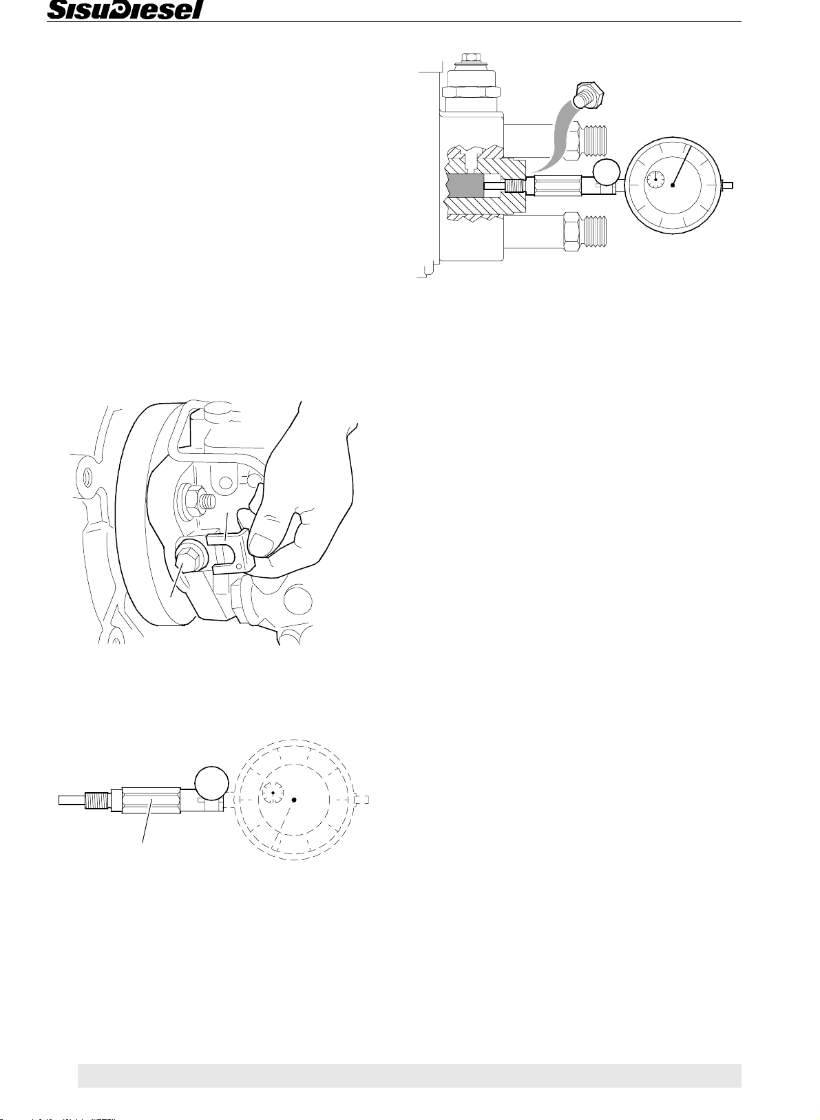
Fuel System
3. Check the condition of the o-rings between the pump
and the timing housing. Change the o-rings if needed.
Lubricate the o-rings and fit the assembling ring into the
timing housing.
Note! Use gasket sealant on the surfaces against the timing housing.
4. Place a new seal on the pump flange. Push the injection pump into place on the timing gear housing.
5. Fit the gear to the coupling flange of the injection
pump. Tighten the screws to 35 Nm.
6. Lock the crankshaft and tighten the nut of the coupling flange to 92,5 Nm. Fit the pump gear cover.
Note! The shaft of the injection pump is locked by a lock
screw. If the shaft slips when tightening the flange nut,
the injection pump will be damaged and must be replaced!
8. Remove the screw (tool size 12 mm), in the middle of
the back of the pump and fit the dial gauge into position.
9. Rotate the crankshaft opposite to running direction
until the movement of the dial gauge stops (piston of the
injection pump is in bottom dead centre). Set the dial
gauge to zero.
2
1
7. Open the lock screw (1) a little and fit the plate (2),
that came with the pump, under the screw. Tighten the
screw to 12,5 Nm. The shaft of the injection pump is
free now.
8366 62521
Setting tool for the injection pump. Adapter 8366 62521
and dial gauge (1/100 mm).
10. Rotate the crankshaft slowly in running direction until the mark on the crankshaft pulley is at the point of the
timing indicator. Read the distance of the injection
pump piston from the dial gauge, it should be 0,30 mm.
If the dial gauge shows different distance, turn the injection pump, depending on the need and check again.
11.When distance of the pump piston is correct, tighten
the retaining nuts of the injection pump.
12. Fit the injection pipes and check that they are in correct angles to the unions. Tighten the delivery pipe attaching nuts to 25 Nm. Do not overtighten!
13. Fit the fuel pipes, throttle cable and the electric wire.
14. The fuel system bleeding starts with opening the
fuel return pipe connection and pumping with the hand
pump until the injection pump housing is filled with fuel.
Tighten the connection. Open the injection pipe connections from the injector end (only about half turn, not more). Crank the engine for about 5 seconds, until fuel
comes out from every injection pipe. Tighten the injection pipe connections and start the engine. Clean off the
over flown fuel.
Note! If needed, a vacuum pump can be connected to
the fuel return connection. The pump sucks the fuel
from the tank via the injection pump. Connect the return
pipe when fuel flows out from the return connection.
13 87
Page 89
Fuel System
Bosch VP 30 and VP 44 rotary pump
Technical data
Injection pump
Type .............................................................................................Bosch VP 30 or VP 44 rotary pump
Fitting position º BTDC (static):
- VP 30 pump in 44-, 66- and 74-engines ....................................30º
- VP 44 pump in 74-engines......................................................... 26º
- VP 44 pump in 84-engines......................................................... 28º
Supply voltage.............................................................................. 12 V
Minimum voltage, at full load........................................................ 7 V
Minimum voltage, at idle speed.................................................... 6 V
Current drain (constant) ............................................................... max. 8 A
Direction of rotation from the engine front.................................... Clockwise
Injection order:
- 44-engines .................................................................................1 - 2 - 4 - 3
- 66-, 74- and 84-engines.............................................................1 - 5 - 3 - 6 - 2 - 4
Fuel system
Fuel ..............................................................................................The fuel must be according to norm EN 590
Fuel filters:
- Pre-filter .....................................................................................Stanadyne 30 µ, element no. 8368 66575
- Fuel filter .................................................................................... Stanadyne 5 µ, element no. 8368 66577
Feed pump ................................................................................... Electric type, with pre-filter
Supply voltage.............................................................................. 12 V
Current drain ................................................................................ max. 6 A
Feed pressure at idle speed......................................................... 1,0…1,2 bar, minimum 0,7 bar
Tightening torques
Injection pump retaining nuts M8 / VP 30 ....................................30 Nm
Injection pump retaining nuts M10 / VP 44 ..................................50 Nm
Injection pump gear retaining screws........................................... 35 Nm
Injection pump overflow valve ...................................................... 27 Nm
Delivery pipe attaching nut to pump.............................................25 Nm
88 13
Page 90
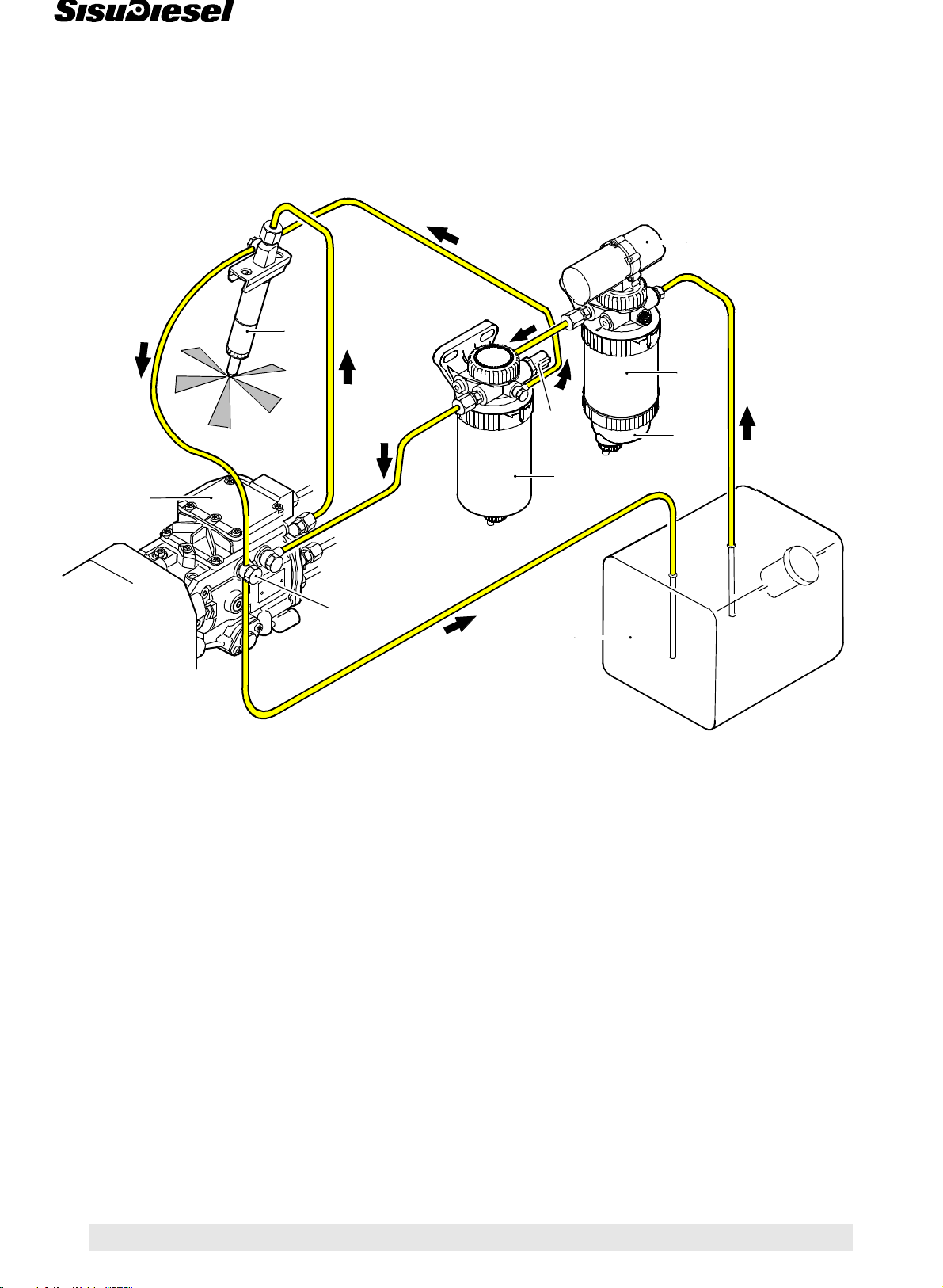
Fuel System
Fuel system, description
The Fortius series engines are using a solenoid controlled Bosch injection pump. The model of the rotary type
injection pump is either VP 30 or VP 44, depending on
the power range.
7
4
2
9
3
5
6
8
1
Fuel system (injection pump Bosch VP 44)
1. Fuel tank 6. Injection pump
2. Pre-filter 7. Injector
3. Water separator (optional) 8. Overflow valve
4. Feed pump 9. Feed pressure sensor (0,05 - 0,2 bar)
5. Fuel filter
The fuel is pumped by electric feed pump from the tank
via a pre-filter, trough the filter to the injection pump.
The injection pump forces the fuel into the injector that
feeds fuel into the combustion space in fine spray. Excess fuel returns from the fuel injection pump through
an overflow valve to the fuel tank. The overflow pipe
between filter and injectors helps the automatic bleeding of the system.
13 89
The fuel system is equipped with a pressure sensor that
alarms before interference has developed. An option
the pre-filter can be equipped with a see-trough water
trap and with an electronic water in fuel sensor.
Page 91
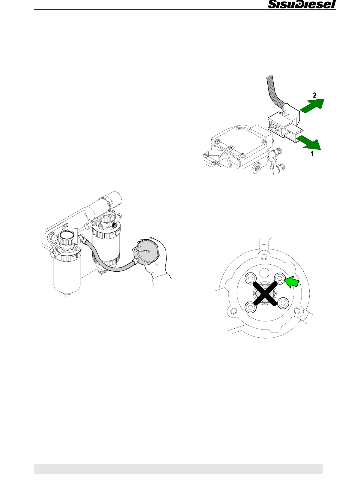
Fuel System
A. Bleeding fuel system
The Fortius series engines have an automatic fuel bleeding system. Changing the fuel filters or lack of fuel
does not require any separate bleeding. It is enough to
switch on the current and let the electric feed pump
work for about 30 seconds before start.
Note! In connection with service- or repair work (like
change of injection pump), there might be a situation
where bleeding the air requires special measures. In
this case open the injection pipe connections from the
injector end (only about half turn, not more). Let the
feed pump work for about 30 - 45 seconds and crank
the engine about 5 seconds, until fuel comes out from
every injection pipe. Retighten connections and start
the engine. Clean off the over flown fuel.
B. Measuring fuel feed pressure
1. Clean up the pre-filter and the fuel filter and related
fuel pipes from outside.
C. Removing fuel injection pump
1. Disconnect the electric main switch. Clean up the injection pump and surroundings.
2. Disconnect the fuel delivery pipes and injection pipes. Fit protective plugs in the fuel pipe connections.
3. Pull up the lock of the electric connector (1) and disconnect the connector (2). Be careful with not touching
the terminals in the connector.
2. Disconnect the pressure switch from the fuel filter
and connect the gauge instead (the thread is M14x1,5).
3. Run the engine at low idling for a while and compare
the gauge reading with the prescribed value (1,0…1,2
bar, minimum 0,7 bar).
Note! If the measured pressure is below the prescribed
value, this may be caused by:
• Clogged fuel filters.
• Malfunction of the feed pump.
• Suction piping clogged or leaking air.
• Empty fuel tank or unsuitable fuel (e.g. summer
fuel in the winter).
4. Remove the injection pump gear cover. Rotate the
crankshaft until the piston of the 1st cylinder reaches its
top dead centre in the compression stroke.
5. Unscrew the retaining screws of the gear (4 pcs) and
retaining nuts of the pump. Remove the injection pump.
CAUTION! NEVER OPEN THE NUT OF THE INJECTION PUMP HUB. The hub can be fitted back only in
test bench.
Note! If the front cover of the timing housing has not
been removed, the gear of the VP 30 pump and the idler
gear will stay in gear connection with each other. The
gear of the VP 44 pump can be removed, ensure therefore the alignment of the timing marks or make your
own marks before removing the gear.
90 13
Page 92
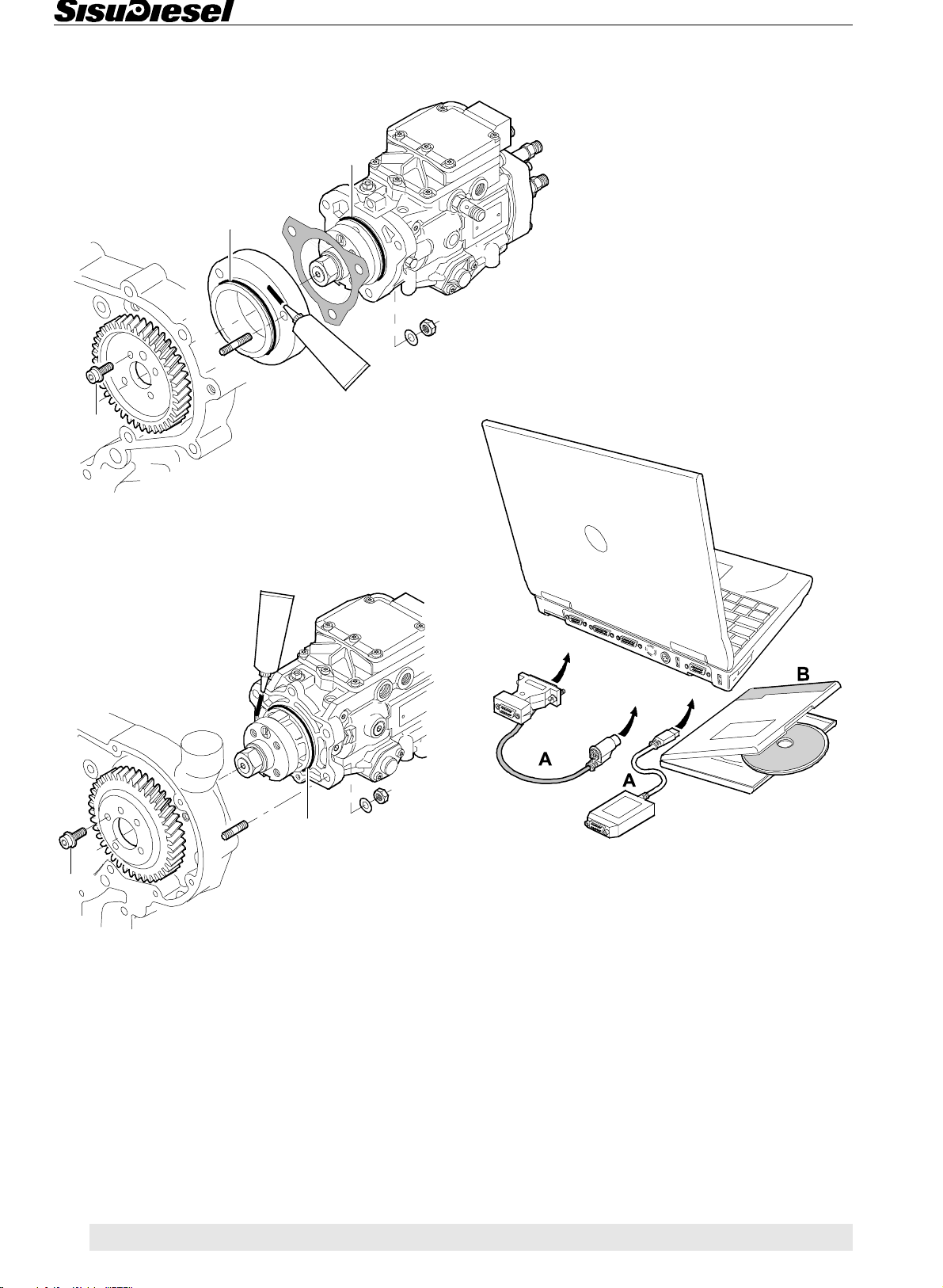
D. Fitting fuel injection pump
A
35 Nm
Fuel System
A
S
E
G
A
L
A
A
S
N
K
T
E
T
Injection pump VP 30 with mounting parts
A = O-ring seals
T
T
N
E
A
L
K
A
S
E
A
S
G
A
35 Nm
Injection pump VP 44 with mounting parts
A = O-ring seals
The injection pump is fitted in position according to the
static basic advance shown using the mark on the crank
shaft pulley / damper and using the special tool that focuses the position of the injection pump.
Parallel
PS/2
1
USB
2
Note! Changing a injection pump is possible to completion by using SisuEEM2 service tool.
This service tool that includes a CAN adapter (A
or A2)
1
and a WinEEM2s program (B) is used with a laptop.
See details from the chapter "Engine Control Sys-
tem".
Also an extension cable (D9 fully connected pin to pin
connector) is available and an adapter to the vehicle
connector. See details from the chapter "Engine Cont-
rol System".
The sale and supply of the service tool and the additional parts is done by Sisu Diesel Inc. Service Department.
13 91
Page 93
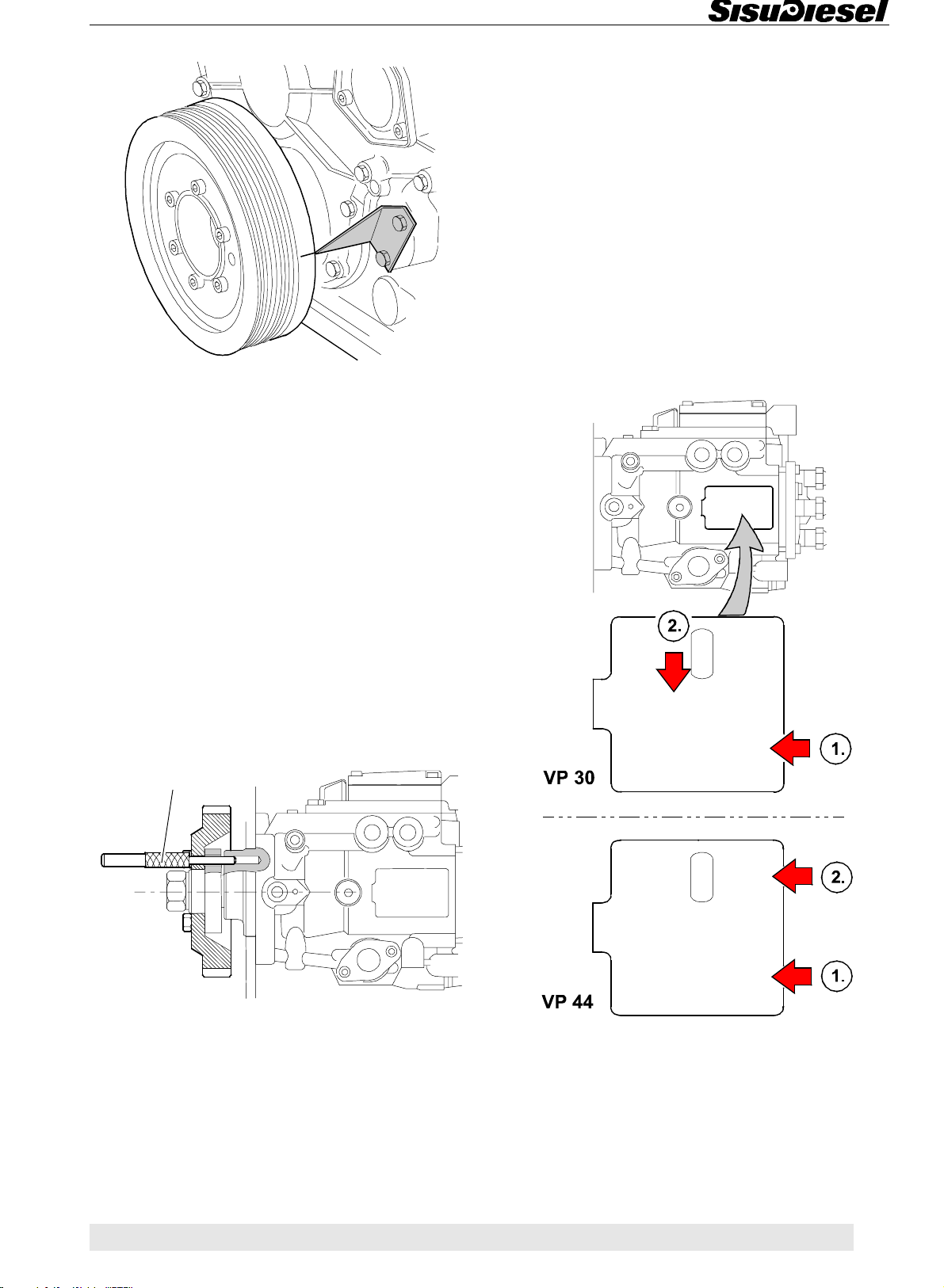
Fuel System
1. Turn the crankshaft to a position where the 1st cylinder piston reaches its compression stroke top dead
centre. Then turn the crankshaft backwards until the
mark on the pulley passes the timing indicator. After
that rotate the crankshaft slowly to running direction until the mark on the pulley is at the point of the timing indicator.
4. Tighten the retaining screws and nuts of the injection
pump and the gear. Pull out the timing pin and fit the
pump gear cover.
5. Fit the pipes without tension and check that they are
at right angles to the union. Tighten the delivery pipe attaching nuts to 25 Nm. Do not overtighten!
6. Fit the other detached parts.
7. Bleed the fuel system, see instruction 13 A.
Note! If the injection pump has been changed, the EEM
2 engine control system has to be fed with the new
serial numbering of the pump using the SisuEEM2 service tool, in the order shown in the picture below. See
more specifically in the service tool manual.
Note! Pulley / vibration damper delivered as spare part
do not have installation mark of the injection pump, see
instruction 5 H.
2. Check the condition of the o-rings between the pump
and the timing housing. Change the o-rings if needed.
Lubricate the o-rings and fit the assembling ring (not
used with VP 44 pumps in 74-engines) into the timing
housing.
Note! Use gasket sealant on the surfaces against the timing housing.
9109 80100
37990
Made in Germany
0470006004
015
288
BOSCH
41098
Made in Germany
011
BOSCH
042401
283
0470506042
142351
000
3. Fit the injection pump in position, so that timing pin
9109 80100 goes easily into the inspection hole through
the injection pump gear and finally to the pump housing.
Ensure at the same time that the timing marks on the
gears are against each other. See types of marking
from the chapter 9. 33-, 44-, 66- and 74-engines point C
and 84-engines point B.
92 13
Page 94
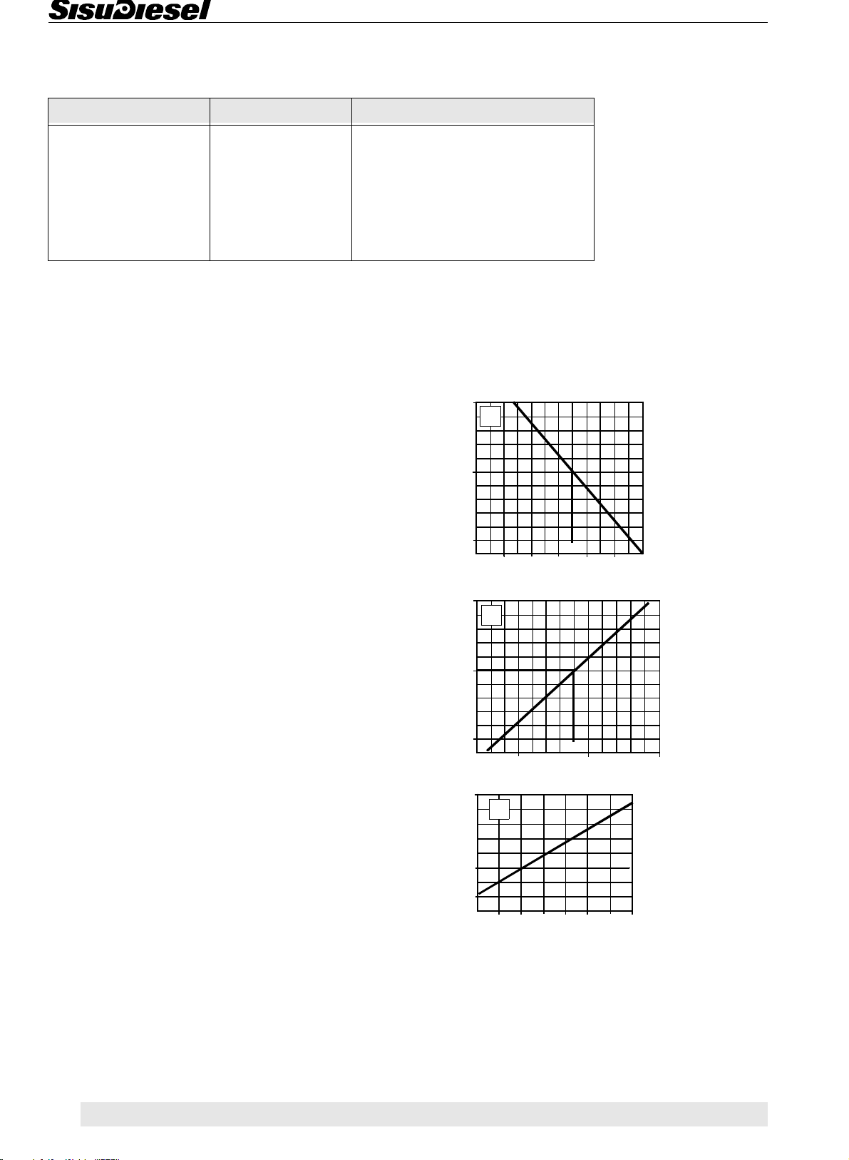
Fuel System
E. Fuel quality requirements
Requirement Test method
3
Density, +15°C
Viscosity, +40°C
0,82...0,84 kg/dm
2,0...4,5 mm
2
/s
Sulphur content max. 0,005 p-% EN ISO 14596:1998
Cetane number min. 51 EN ISO 5165:1998
Water content max. 200 mg/kg prEN ISO 12937:1996
lubricity/HFRR max. 460 µm ISO 12156-1
The fuel must be according to norm EN 590.
Engine output depending on fuel quality
Different fuel qualities like temperature, density and viscosity affect the actual output of the engine. Our outputs
are specified by fuel with a density of 0.84 kg/dm
specific heat rate of 42,7 Mj/kg at a fuel temperature of
+15°C.
EN ISO 3675:1998, EN ISO 12185
EN ISO 3104
3
and
OUTPUT %
+5
A
The correction in % caused by the change of fuel qualities is seen in the attached figures.
FIG. A. Engine output dependence on fuel temperature.
+35°C is the reference temp (correction 0%). The fuel
temperature is not only a function of ambient conditions
but also varies according to the fuel system of the application (tank size and location, return flow etc.).
FIG. B. Engine output dependence on fuel density. Normal value is 0,84 kg/dm
3
at +15°C.
FIG. C. Engine output dependence on fuel viscosity.
Normal value is 3 cSt at +20°C.
Note fig. B and C only if the fuel quality is changed.
In fig. A there are all the quality dependencies caused
by the change of the temperature. The fuel density and
viscosity can be seen in the produce declaration given
by the manufacturer.
The output correction is made as follows: Correction
percentages from figures A, B and C are summed up.
The given rated power is then corrected with the resulting percentage.
0
-5
OUTPUT %
+5
B
0
-5
OUTPUT %
+5
0
-2
10 20
0,80
C
2
35
30
FUEL TEMPERATURE °C
0,84
34
56
VISCOSITY cSt
40 50 60
0,85
DENSITY kg/dm
78
0,90
3
13 93
Page 95
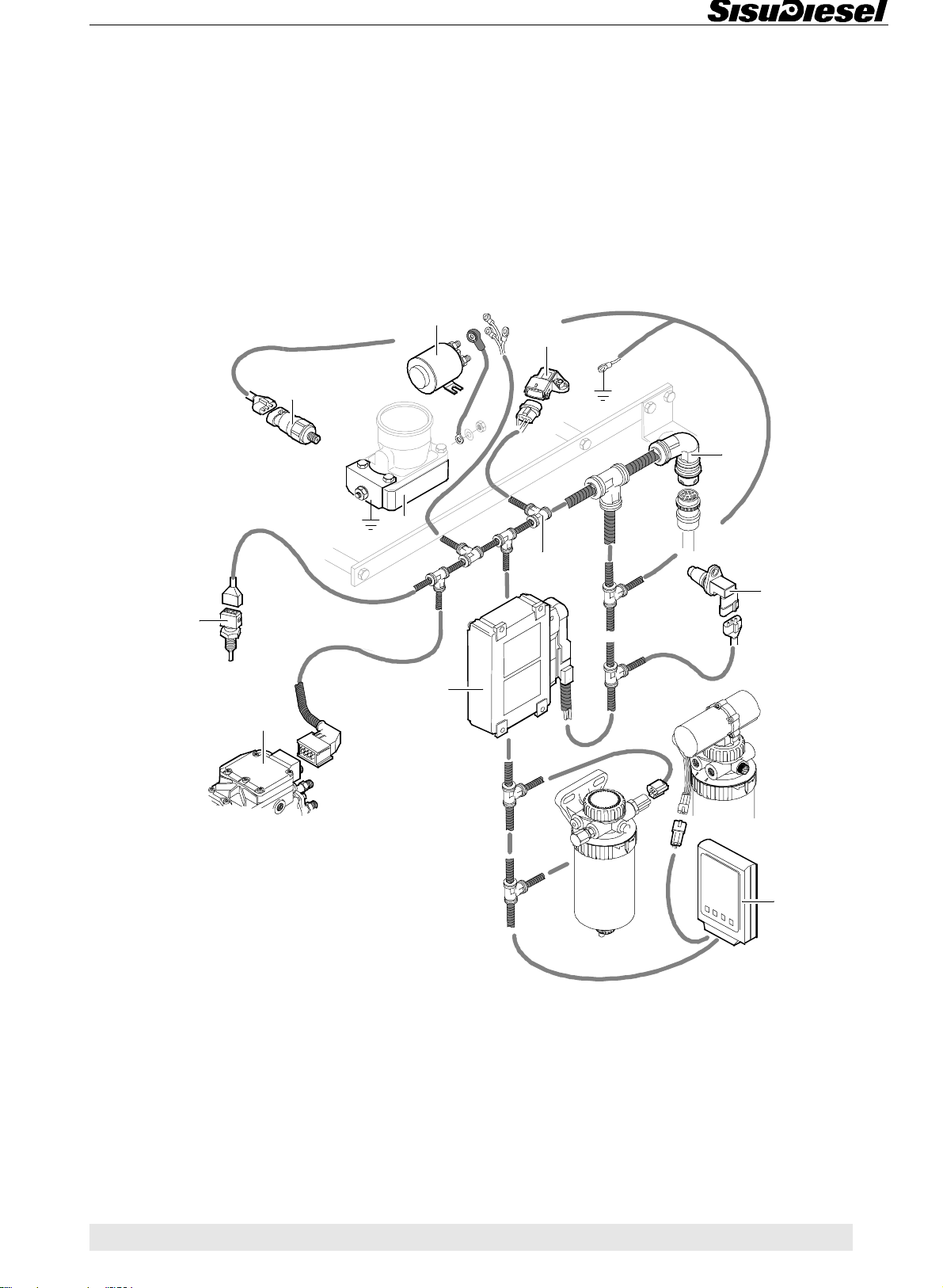
Engine Control System
14. ENGINE CONTROL SYSTEM EEM 2
Fortius series engine fulfils the emission requirements set by authorities (EU97/68/EC Stage 2 and EPA 40 CFR 89
Tier 2). The manufacturer guarantees that all engines of this type are equivalent to the engine that is officially approved. This must be noticed especially when performing periodical maintenance, follow carefully the service
schedule. Any adjusting and repair work for the injection system or the engine control unit can only be made by a
representative authorized by Sisu Diesel Inc. When performing any service or repair work use only original SisuDiesel spare parts. Inadequate or delayed service and the use of other than original SisuDiesel spare parts invalidates
the responsibility of Sisu Diesel Inc. on the fulfilment of the emission requirements.
Construction of the EEM 2
6
7
3
11
5
8
4
2
1
10
9
Parts of engine control system
1. Electronic control unit (ECU) 7. Boost pressure sensor
2. Coolant temperature sensor 8. Wiring set of engine
3. Oil pressure sensor 9. Voltage reducer 24 V > 12 V
4. Speed sensor 10. Pump control unit (PCU)
5. Electric intake air heater 11. Vehicle connector
6. Solenoid for intake air heater
94 14
14
Page 96
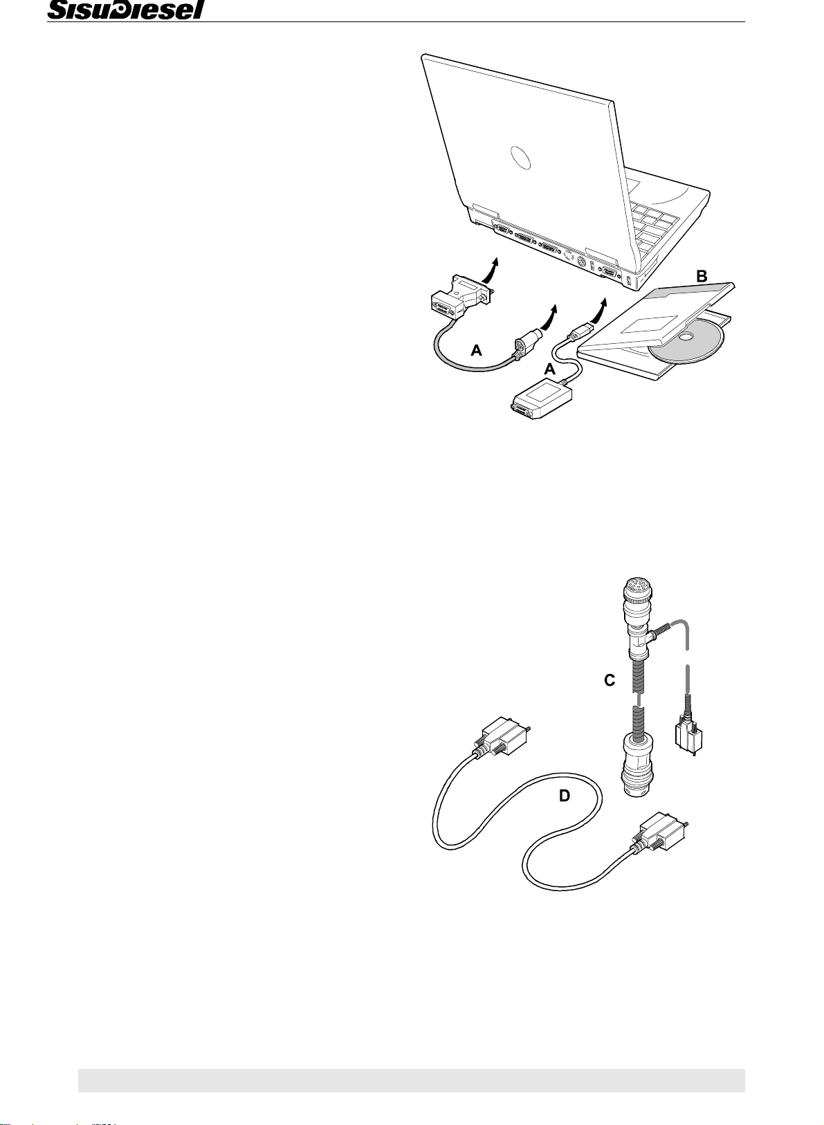
Engine Control System
EEM 2 Engine Control System, description
The basic function of the electric control of the engine is
continuos adjustment and measuring of the load, quantity of fuel and rotating speed. Other additional function
are for example cold start automatics and engine protecting automatics. The central unit of the electric control receives continuously signals from sensors that
measure different functions in the engine like rotating
speed, oil pressure, turbo pressure and coolant temperature. Through the CAN bus the central unit gets information from the control unit of the injection pump and
from the cabin about the need of load for the engine.
The EEM 2 unit makes it also possible to have a wide
diagnostics through code numbers or a diagnostic light.
Parallel
PS/2
USB
Service tool of EEM 2 system
The EEM 2 engine control system can only be ruled by
this service tool with additional parts.
This service tool, used together with a lap top, can be
used for adjusting the EEM 2 system, like running
speed adjusting, running hours adjusting (only adding is
possible) and throttle calibration. As well following the
fault diagnostics, updating software and other service
related purposes, like reading of running- and shutdown
memory are easy to do.
Repairing work, like changing a injection pump or electronic control unit (ECU), is possible to completion by
using SisuEEM2 service tool.
In addition, the service tool can be used to clear up the
stopping requests made, not depending of the engine,
for example power cuts or under voltage (like earthproblems, power needed when engine running ~10 A
and voltage >7 V) in the machine and the stopping requests caused by the gear box.
The service tool includes a license number. Each time
an engine has been connected to the service tool, for
adjustments or any other reason, this license number is
found in the EEM 2 system.
1
2
8366 62478 SisuEEM2 service tool
A
CAN adapter for connection via parallel port
1
B WinEEM2s program
8366 62493 SisuEEM2 service tool
A
CAN adapter for connection via USB port
2
B WinEEM2s program
1500 mm
The sale and supply of the service tool and the additional parts is done by Sisu Diesel Inc. Service Department.
14 95
Also an adapter to the vehicle connector and an extension cable (D9 fully connected pin to pin connector, 5 m)
is available.
C 8368 62480 Adapter for vehicle connector
D 8368 62483 Extension cable L = 5 m
Page 97
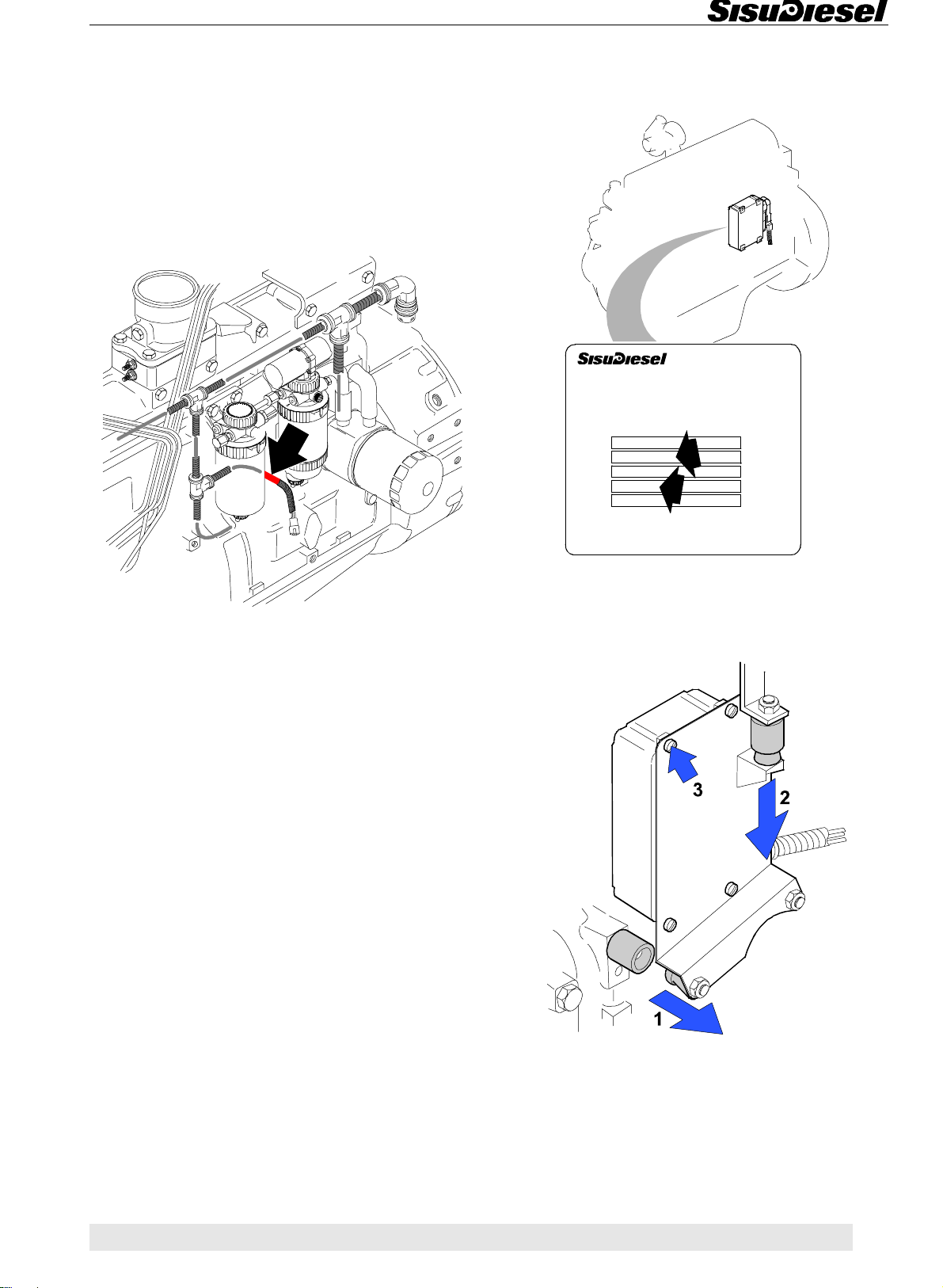
Engine Control System
The service tool can be connected using the adapter if
the engine is using any of following wiring harness:
• Order no. 8367 66799
• Order no. 8368 66719
• Order no. 8368 66795
• Order no. 8368 66955
• Order no. 8368 67071
A. Changing of Control Unit (ECU)
Manufacturer
SISU Diesel Inc.
FIN-37240 Linnavuori
EEM 2
Engine Control Unit
Hw. ver.
Partno
836864630
Cust.
Partno
Engi ne
M07575
Serial nr
Type
74 ETA
FINLAND
Order number of wiring harness is printed on red label
as shown in picture (optional water detector connector
wire).
Note! The specification of the application and the engine serial number are indicated on the type plate of the
EEM 2 control unit. These numbers must always be stated when ordering a control unit.
1. If the central unit is attached to the engine, pull the fixing stand first out from the rubber mounts (1), then
push the stand downward (2). Finally loosen the tightening screws (3).
96 14
Page 98
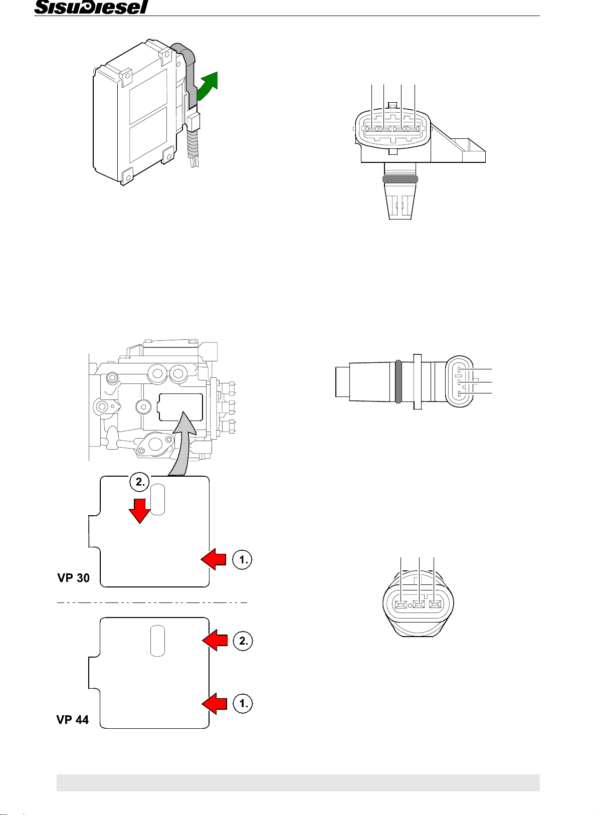
Engine Control System
2. Loosen the multi pin connector from the central unit,
opening the locking latch. Be careful with not touching
the terminals in the connector.
3. Attach the new central unit in opposite order.
Note! After changing of the central unit, the EEM 2 engine control system has to be fed with the new serial
numbering of the pump using the SisuEEM2 service
tool, in the order shown in the picture below. See more
specifically in the service tool manual.
B. Sensors of Engine Control System
Boost pressure sensor
2
34
1. Ground
2. Temperature signal
3. +5 V
4. Pressure signal
Location: Inlet manifold
Screw M5 / 3,3 Nm
1
Speed sensor
3
2
1
1. Ground
2. Rpm signal
3. +12 V
37990
Made in Germany
0470006004
015
288
BOSCH
41098
Made in Germany
011
042401
283
0470506042
Location: Cylinder block, left side
Screw M8 / 25 Nm
O-ring, order no. 6146 01524
Oil pressure sensor
1
23
BOSCH
142351
000
14 97
1. Ground
2. Pressure signal
3. +5 V
Location: Cylinder block, right side
Thread M10x1 / 25 Nm
Seal ring, order no. 6158 71016
Page 99
Electrical System
15. ELECTRICAL SYSTEM
A. Alternators
Bosch N1 28 V 10/80 A (SisuDiesel no. 8353 39751)
Nominal voltage . . . . . . . . . . . . . . . . . . . . . . . . . . . . . . . . . . . . . . . . . . 24 V
Output
1500 r/min . . . . . . . . . . . . . . . . . . . . . . . . . . . . . . . . . . . . . . . . . . . . .16 A
2700 r/min . . . . . . . . . . . . . . . . . . . . . . . . . . . . . . . . . . . . . . . . . . . . .53,5 A
6000 r/min . . . . . . . . . . . . . . . . . . . . . . . . . . . . . . . . . . . . . . . . . . . . .79 A
Min. slip ring diameter . . . . . . . . . . . . . . . . . . . . . . . . . . . . . . . . . . . . . . 26,8 mm
Brush length when new. . . . . . . . . . . . . . . . . . . . . . . . . . . . . . . . . . . . . 19 mm
Min. brush length. . . . . . . . . . . . . . . . . . . . . . . . . . . . . . . . . . . . . . . . . . 5 mm
Rotor resistance . . . . . . . . . . . . . . . . . . . . . . . . . . . . . . . . . . . . . . . . . . 7,5...8,2 ohm
Stator resistance . . . . . . . . . . . . . . . . . . . . . . . . . . . . . . . . . . . . . . . . . . 0,057...0,062 ohm
Regulating voltage . . . . . . . . . . . . . . . . . . . . . . . . . . . . . . . . . . . . . . . . 28 V
Tightening torques:
Shaft nut. . . . . . . . . . . . . . . . . . . . . . . . . . . . . . . . . . . . . . . . . . . . . . 55 Nm
Assembling screws . . . . . . . . . . . . . . . . . . . . . . . . . . . . . . . . . . . . . 4,1...5,5 Nm
Regulator screws . . . . . . . . . . . . . . . . . . . . . . . . . . . . . . . . . . . . . . . 1,6...2,3 Nm
Joint B- (M6) . . . . . . . . . . . . . . . . . . . . . . . . . . . . . . . . . . . . . . . . . . 4,8...6,8 Nm
Joint W (M5). . . . . . . . . . . . . . . . . . . . . . . . . . . . . . . . . . . . . . . . . . . 2,7...3,8 Nm
Joint D+ (M4) . . . . . . . . . . . . . . . . . . . . . . . . . . . . . . . . . . . . . . . . . . 1,6...2,3 Nm
Joint B+ (M8) . . . . . . . . . . . . . . . . . . . . . . . . . . . . . . . . . . . . . . . . . . 7,5...8,0 Nm
Bosch N1 28 V 0/100 A (SisuDiesel no. 8353 40374)
Nominal voltage . . . . . . . . . . . . . . . . . . . . . . . . . . . . . . . . . . . . . . . . . . 24 V
Output (warm generator, testing voltage 26 V)
2000 r/min . . . . . . . . . . . . . . . . . . . . . . . . . . . . . . . . . . . . . . . . . . . . .26 A
3500 r/min . . . . . . . . . . . . . . . . . . . . . . . . . . . . . . . . . . . . . . . . . . . . .72 A
7000 r/min . . . . . . . . . . . . . . . . . . . . . . . . . . . . . . . . . . . . . . . . . . . . .94 A
Min. slip ring diameter . . . . . . . . . . . . . . . . . . . . . . . . . . . . . . . . . . . . . . 26,8 mm
Brush length when new. . . . . . . . . . . . . . . . . . . . . . . . . . . . . . . . . . . . . 19 mm
Min. brush length. . . . . . . . . . . . . . . . . . . . . . . . . . . . . . . . . . . . . . . . . . 5 mm
Rotor resistance . . . . . . . . . . . . . . . . . . . . . . . . . . . . . . . . . . . . . . . . . . 7,5...8,2 ohm
Stator resistance . . . . . . . . . . . . . . . . . . . . . . . . . . . . . . . . . . . . . . . . . . 0,038...0,041 ohm
Regulating voltage . . . . . . . . . . . . . . . . . . . . . . . . . . . . . . . . . . . . . . . . 28,5 V
Tightening torques:
Shaft nut. . . . . . . . . . . . . . . . . . . . . . . . . . . . . . . . . . . . . . . . . . . . . . 70 Nm
Assembling screws . . . . . . . . . . . . . . . . . . . . . . . . . . . . . . . . . . . . . 4,1...5,5 Nm
Regulator screws . . . . . . . . . . . . . . . . . . . . . . . . . . . . . . . . . . . . . . . 1,6...2,3 Nm
Joint B- (M6) . . . . . . . . . . . . . . . . . . . . . . . . . . . . . . . . . . . . . . . . . . 4,8...6,8 Nm
Joint W (M5). . . . . . . . . . . . . . . . . . . . . . . . . . . . . . . . . . . . . . . . . . . 2,7...3,8 Nm
Joint D+ (M4) . . . . . . . . . . . . . . . . . . . . . . . . . . . . . . . . . . . . . . . . . . 1,6...2,3 Nm
Joint B+ (M8) . . . . . . . . . . . . . . . . . . . . . . . . . . . . . . . . . . . . . . . . . . 7,5...8,0 Nm
98 15
Page 100
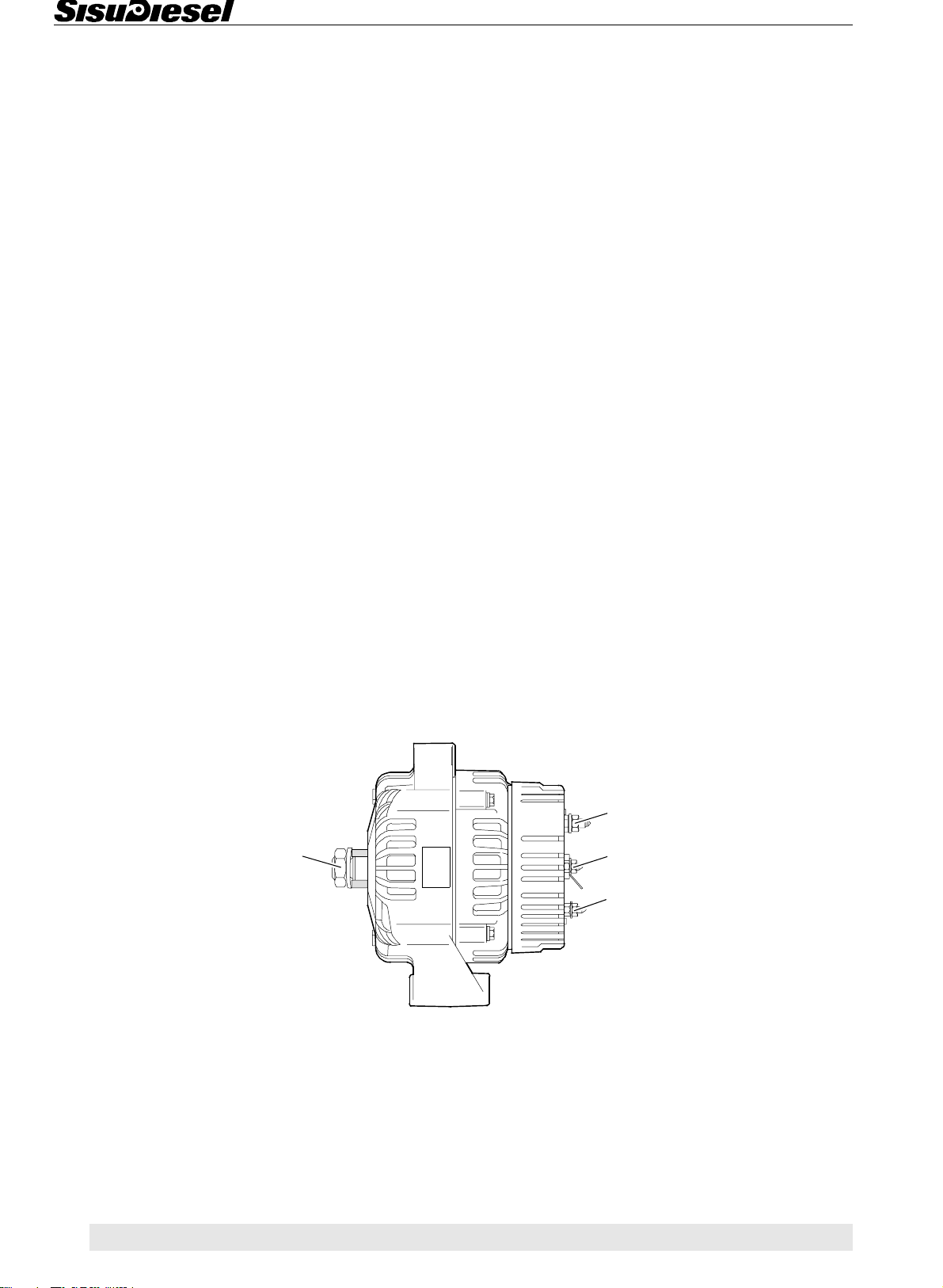
Electrical System
Bosch NC 14 V 150 A (Sisu Diesel no. 8368 64048)
Nominal voltage . . . . . . . . . . . . . . . . . . . . . . . . . . . . . . . . . . . . . . . . . . 12 V
Min. slip ring diameter . . . . . . . . . . . . . . . . . . . . . . . . . . . . . . . . . . . . . . 14,9 mm
Brush length when new . . . . . . . . . . . . . . . . . . . . . . . . . . . . . . . . . . . . . 12,5 mm
Min. brush length. . . . . . . . . . . . . . . . . . . . . . . . . . . . . . . . . . . . . . . . . . 5 mm
Tightening torques:
Shaft nut . . . . . . . . . . . . . . . . . . . . . . . . . . . . . . . . . . . . . . . . . . . . . . 60...70 Nm
Joint B+ (M8) . . . . . . . . . . . . . . . . . . . . . . . . . . . . . . . . . . . . . . . . . . 10 Nm
Joint D+ (M5) . . . . . . . . . . . . . . . . . . . . . . . . . . . . . . . . . . . . . . . . . . 5 Nm
Iskra AAK 3369 14 V 65 A (SisuDiesel no. 8366 66723)
Nominal voltage . . . . . . . . . . . . . . . . . . . . . . . . . . . . . . . . . . . . . . . . . . 12 V
Output (test voltage 13 V)
2000 r/min . . . . . . . . . . . . . . . . . . . . . . . . . . . . . . . . . . . . . . . . . . . . 38 A
4000 r/min . . . . . . . . . . . . . . . . . . . . . . . . . . . . . . . . . . . . . . . . . . . . 61 A
6000 r/min . . . . . . . . . . . . . . . . . . . . . . . . . . . . . . . . . . . . . . . . . . . . 65 A
Charge begins . . . . . . . . . . . . . . . . . . . . . . . . . . . . . . . . . . . . . . . . . . . . 1150 r/min
Max. allowed speed . . . . . . . . . . . . . . . . . . . . . . . . . . . . . . . . . . . . . . . 12 000 r/min
Min. slip ring diameter . . . . . . . . . . . . . . . . . . . . . . . . . . . . . . . . . . . . . . 27 mm
Min. brush length. . . . . . . . . . . . . . . . . . . . . . . . . . . . . . . . . . . . . . . . . . 5 mm
Rotor resistance . . . . . . . . . . . . . . . . . . . . . . . . . . . . . . . . . . . . . . . . . . 2,70...2,97 ohm
Stator resistance . . . . . . . . . . . . . . . . . . . . . . . . . . . . . . . . . . . . . . . . . . 1,60...1,80 ohm
Tightening torques:
1. Shaft nut . . . . . . . . . . . . . . . . . . . . . . . . . . . . . . . . . . . . . . . . . . . 50...70 Nm
2. Joint B+ (M6) . . . . . . . . . . . . . . . . . . . . . . . . . . . . . . . . . . . . . . . . 4,2...6,0 Nm
3. Joint D+ (M5) . . . . . . . . . . . . . . . . . . . . . . . . . . . . . . . . . . . . . . . . 2,7...3,8 Nm
4. Joint W (M 5) . . . . . . . . . . . . . . . . . . . . . . . . . . . . . . . . . . . . . . . . 2,7...3,8 Nm
1
2
3
4
15 99
 Loading...