

Page 1

SCH2P
Sirius Satellite Radio Connect Tuner
Installation and User Guide
Page 2
Congratulations on the purchase of your new SIRIUS Connect
SCH2P Satellite Radio Tuner
Your new SC H2P SIRIUS® Connect Tu ner is designed to work with SIRIUS-ready receivers.
Consult the SIRIUS website at http://www.sirius.com for model compati bility.
What is Sirius Sate llite R adio ?
Over 120 ch ann els of the bes t e ntertai nment a nd complet ely com mercial -fr ee musi c for
your car, h ome or off ice.
Only SIRIUS has more than 65 original music channels, from today’s hi ts to R&B oldies to
classical m asterpieces. From authentic country and real bluegrass to cool jazz, hot la tin, reggae, rock, and many more. Best of all, it’s all completely commercial -free.
SIRIUS also has more than 55 channels of world-class sports, news, an d entertainment.
Included as part of your subscription, you get up to 16 NFL games a w eek, up to 40 NBA
games a wee k, and up to 40 NHL games a week. (Games are broadcast dur ing their respective season s.) Coupled with great sports news from ESPN, the SIRIUS s ports offering is
unrivaled. And don’t forget a host of other great news and entertainm ent, like NPR, CN BC,
Fox News, R adio Disney, and E! Entertainment Radio. For more informat ion, visit the SI RIUS
website at http://www.sirius.com.
Page 3

Table of Contents
TABLE OF CONTENTS . . . . . . . . . . . . . . . . . . . . . . . . . . . . . . 3
WARNING AND SAFETY INFORMATION . . . . . . . . . . . . . . . . . . . . . . 4
Important Safety Instructions . . . . . . . . . . . . . . . . . . . . . . . . . . . .4
FCC Warning . . . . . . . . . . . . . . . . . . . . . . . . . . . . . . . . . . 5
Equipment Warning Labels . . . . . . . . . . . . . . . . . . . . . . . . . . . . 5
PACKAGE CONTENTS . . . . . . . . . . . . . . . . . . . . . . . . . . . . . . 6
CONTROLS AND CONNECTORS . . . . . . . . . . . . . . . . . . . . . . . . . 8
INSTALLATION . . . . . . . . . . . . . . . . . . . . . . . . . . . . . . . . 10
Mounting the Tuner . . . . . . . . . . . . . . . . . . . . . . . . . . . . . . 10
Connecting the AC Power Cord . . . . . . . . . . . . . . . . . . . . . . . . . 11
Installing the Outdoor Antenna . . . . . . . . . . . . . . . . . . . . . . . . . . 11
Connecting the Tuner . . . . . . . . . . . . . . . . . . . . . . . . . . . . . 23
Subscribing to the SIRIUS Service . . . . . . . . . . . . . . . . . . . . . . . . 24
OPERATION . . . . . . . . . . . . . . . . . . . . . . . . . . . . . . . . . 25
TROUBLESHOOTING . . . . . . . . . . . . . . . . . . . . . . . . . . . . . 26
SPECIFICATIONS . . . . . . . . . . . . . . . . . . . . . . . . . . . . . . . 28
COPYRIGHTS & TRADEMARKS . . . . . . . . . . . . . . . . . . . . . . . . 29
SIRIUS ID . . . . . . . . . . . . . . . . . . . . . . . . . . . . . . . . . . 30
[ Table o f Conte nt s ]
3
Page 4

Warning and Safety Information
Important Safety Instructions
Read these instructions.
•
Keep these instructions.
•
Heed all wa rnings.
•
Follow all instructions.
•
Do not use this apparatus near water.
•
Clean only with a dry cloth.
•
Do not bloc k any of the ventilation openings. Install in accordance w ith the manufactu rer’s
•
instruction s.
Do not inst all near any heat sources such as radiators, heat register s, stoves, or oth er ap-
•
paratus (in cluding amplifiers) that produce heat.
Do not defe at the safety purpose of the polarized or grounding type p lug. A polarized plug
•
has two bla des with one wider than the other. A grounding type plug h as two blades and
a third gro unding prong. The wide blade or the third prong is provide d for your safety . If
the provide d plug does not fit into your outlet, consult an electrici an for replacemen t of the
obsolete ou tlet.
Protect the power cord from being walked o n or pinched particularly at plugs, conve nience
•
receptacles , and the point where they exit from the apparatus.
Only use th e attachments specified by the manufacturer.
•
Use only wi th the cart, stand, bracket, or table specified by the man ufacturer, or sol d with
•
the apparat us. When a cart is used, use caution when moving the cart/ apparatus combina tion to avo id injury from tip-over.
Unplug this apparatus during lightning storms or when unused for long periods of time.
•
Refer all s ervicing to qualified service personnel. Servicing is requ ired when the app aratus
•
has been da maged in any way, such as power-supply cord or plug is dam aged, liquid has
been spille d or objects have fallen into the apparatus, the apparatus has been exposed to
rain or moi sture, does not operate normally, or has been dropped.
The apparat us should not be exposed to dripping or splashing liquids. Containers fille d
•
with liquid s, such as vases, cups, soda cans, etc., should be not pla ced on the appara tus.
[ Warni ng a nd Sa fe ty I nform at io n ]
4
Page 5
DISCONNECTI NG POWER FROM THE DEVICE — The AC power cord provided with the
•
device is u sed to disconnect the power from the device. Access to the power cord shoul d
remain easi ly accessible.
FCC Warning
This equipm ent may generate or use radio frequency energy. Changes or modifications to this
equipment m ay cause harmful interference unless the modifications are expressly approv ed in
this instal lation and user guide. The user could lose the authority t o operate this eq uipment if
an unauthor ized change or modification is made.
Note: This equipment has been tested and found to comply with Part 15 of the FCC Rules.
These rules are designed to provide reasonable protection against harmful interference. This
equipment may cause harmful interference to radio communications if it is not installed and used
in accordance with these instructions. However, there is no guarantee that interference will not
occur in a particular installation. If this equipment does cause harmful interference to radio or
television reception, which can be determined by turning the equipment off and on, the user is
encouraged to try to correct the interference by one of more of the following measures:
Relocate th e receiving antenna.
•
Consult the dealer or an experienced technician for help.
•
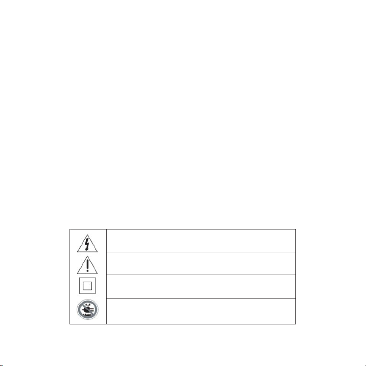
Equipment Warning Labels
This symbol found on apparatus indicates hazards arising
from danger ous voltages.
This symbol found on apparatus indicates the user should
read all sa fety statements found in the user manual.
This symbol found on apparatus indicates double insulation.
Warning! To reduce the risk of fire or electrical shock, do
not expose this apparatus to rain or moisture.
[ Warni ng a nd Sa fe ty I nform at io n ]
5
Page 6
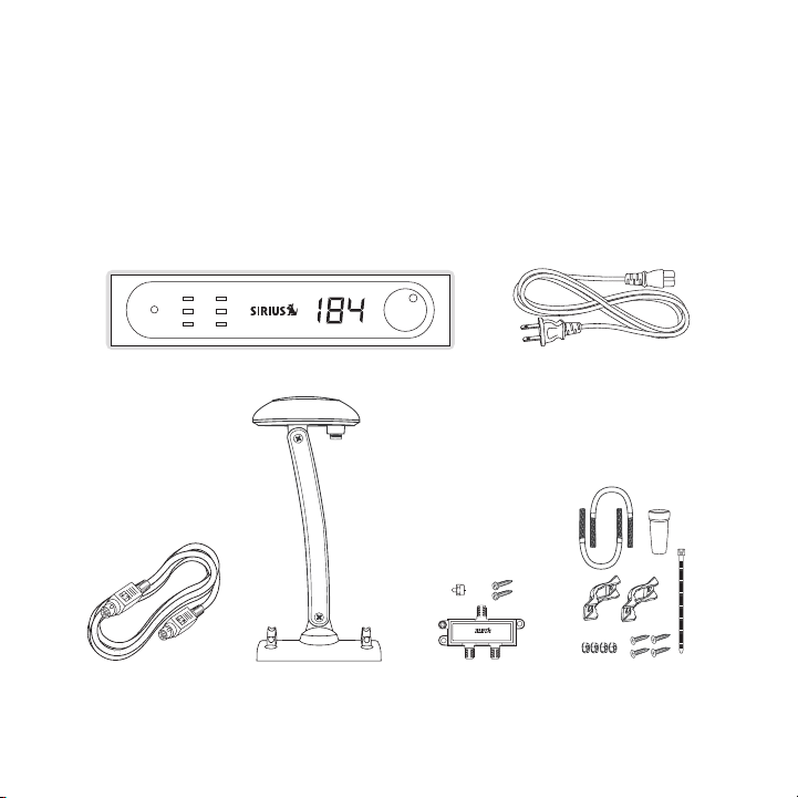
Package Contents
standby sat ter channel
The followi ng items are included with your purchase of the SCH2P SIRI US Connect Tuner.
Unpack the kit carefully and make sure that everything shown is prese nt. If anything i s missing
or damaged, or if the kit fails to operate properly, notify your deal er immediately. I t is recommended that you retain the original carton and packing materials in c ase you need to s hip your
kit in the future.
SIRIU S Con nect TunerSIRIU S Con nect Tuner
DIN C ableDIN C able
[ Packa ge C onten ts ]
6
Outdo or An tennaOutdo or An tenna
Split ter, Mount ing
Screw s, Te rmina tor
AC Po wer C ordAC Po wer C ord
Outdo or An tenna
Mount ing H ardwa re
Page 7
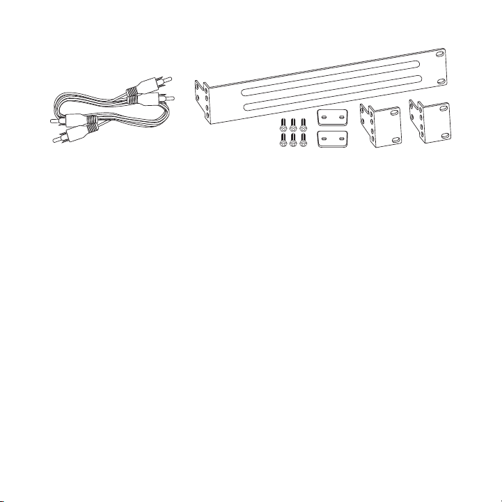
Audio Cabl eAudio Cabl e
Rack Mount ing H ardwa reRack Mount ing H ardwa re
[ Packa ge C onten ts ]
7
Page 8
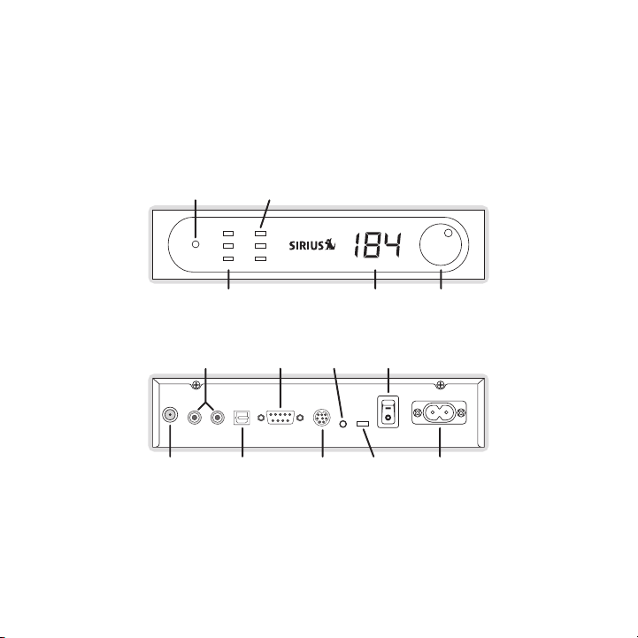
Controls and Connectors
standby sat ter channel
STANDBY
INDICATOR
TERRESTRIAL
SIGNAL STRENGTH
INDICATOR
SATELLITE
SIGNAL STRENGTH
INDICATOR
CHANNEL
DISPLAY
CHANNEL
TUNING
KNOB
ANTENNA OPTICAL
AUDIO OUTPUT
8-PIN
DIN PORT
CONTROL
SWITCH
1 2 3
AC POWER
CONNECTOR
LEFT/RIGHT
AUDIO
OUTPUT
RS232
PORT
INFRARED
CONNECTOR
ON/OFF
SWITCH
Figur e 1Figur e 1
Figure 1 an d the table following identify and describe the displays, controls, and con nectors
of the SCH2 P SIRIUS Connect Tuner.
[ Contr ol s and C on ne ct ors ]
8
Page 9
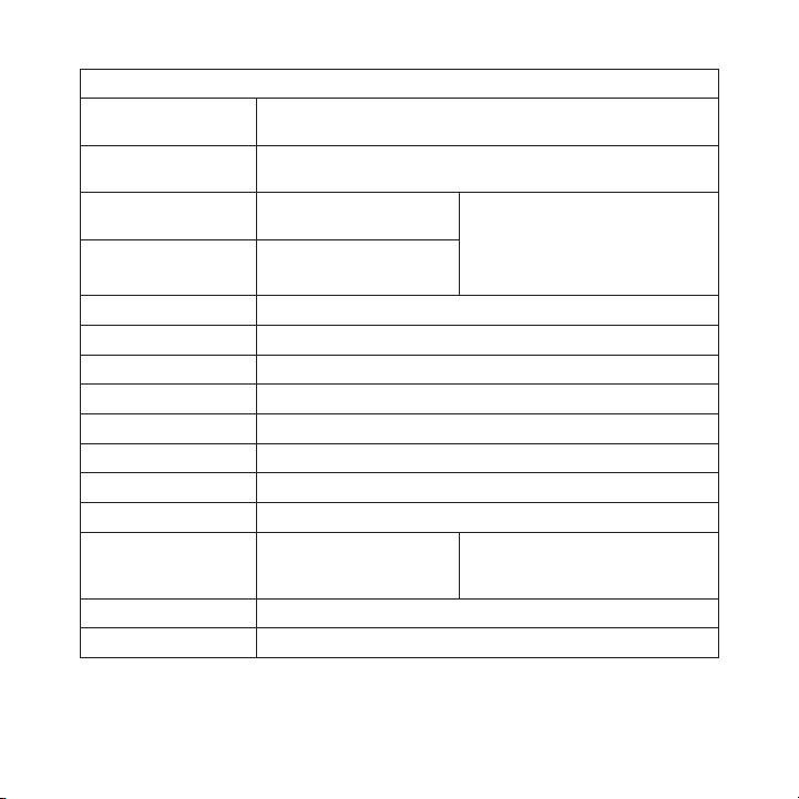
Desc ription of Tuner Display , Controls , and C onnectors
Disp lay/
Cont rol/Con nector
Stan dby
Sat
Ter
Chan nel
Chan nel Tun ing Knob
Ante nna
L - Audio - R
Opt. Audio
RS23 2
8-PI N
IR
Cont rol Swi tch
1 - 2 - 3
On/O ff Swit ch
AC P ower Co nne ctor
Desc ription
Standby ind icator light is lit when power is connected to the
tuner and t he On/Off Switch is On
Satellite s ignal strength
indicator l ights
Terrestrial signal strength
indicator l ights
Displays th e currently tuned channel
Used to tun e the satellite radio channel
Connects to the satellite antenna
Left/Right RCA-type analog audio output connectors
Toslink opt ical digital audio output connector
RS232 inter face connector for tuner control
8-PIN DIN i nterface connector for tuner control and audio output
Infrared co nnector
Switches co ntrol between
the RS232, 8-PIN DIN, or
Infrared co nnector
Turns the p ower to the tuner on and off
Connection for AC power cord
All Off: No Signal
One Light: Weak Signal Level
Two Lights: Good Signal Level
Three Light s: Excellent Signal Level
All Flashin g: Antenna not detected
1. L eft-mos t p osition : RS232
2. C enter p osi tion: 8-PIN DIN
3. R ight-mo st positio n: Infrared
[ Contr ol s and C on ne ct ors ]
9
Page 10
Installation
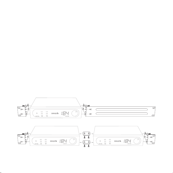
Figur e 2Figur e 2
Figur e 3Figur e 3
It is recom mended that prior to starting the installation, you read t his installation section completely and then follow the instructions. In addition, consult the ma nual of the audio device or
A/V system to which you will be connecting the tuner to determine the required install ation
configurati on.
Mounting the Tuner
When consid ering a mounting location be sure that you avoid any locat ion where the tun er
is exposed to moisture or extreme heat. The tuner can be placed on a flat surface or r ack
mounted usi ng the provided rack mounts.
If you will be rack mounting the tuner, attach the rack mounting hard ware to the tuner as
shown in Fi gure 2. If you have purchased two tuners and are rack moun ting both tuners, attach the ra ck mount hardware as shown in Figure 3.
10
[ Insta ll at ion ]
Page 11

RG-6 Cable
Outdoor
Antenna
Splitter
50’ MAX.
150’ MAX.
Terminator
1
RG-6 Cable
2
Figur e 3Figur e 3
Connecting the AC Power Cord
Connect the AC power cord to the AC power connector at the rear of th e tuner, and plug it
into a wall outlet. (Refer to Figure 1 on page 8.)
Installing the Outdoor Antenna
Before inst alling the outdoor antenna, read this entire section.
A successfu l antenna installation consists of three steps: Fir st, det ermining a locati on for the
antenna; Se con d, choosing a mounting option; and Thi rd, adjusting and aiming the anten na.
Please read the following three sections before beginning the antenna installation so that you
understand the entire installation process.
You will ne ed to purchase two RG-6 cables to complete the installatio n of the antenna. These
cables are the same as the cables used for cable TV installations, an d may be purchase d from
your local hardware store, home center, or electronics retailer. RG-6 cable is typical ly sold in
lengths of 25, 50, or 100 ft., all with “F” type connectors on each e nd.
Figure 3 sh ows the two cables you will need to purchase. The length o f cable 2 cannot
exceed 50 f t., and the overall length of both cables cannot exceed 15 0 ft.
[ Insta ll at ion ]
11
Page 12

Det er mi nin g a Loc ati on fo r the a nt en na
No obstructions to the
sky within this area
Figur e 4Figur e 4
For correct operation and best reception of the SIRIUS signal, it is important that the outdoor
antenna is located in a place where it will have a clear view of the SIRIUS satellites in the sky.
Obstructions such as bushes, trees, other homes or buildings, overhangs, soffits, chimneys,
gables, dormers, etc., will impair or prevent the antenna from receiving a signal.
The best reception is obtained if the pod portion of the antenna (where the SIRIUS logo is printed) has a clear 360 degree view of the sky within the cone-shaped area as shown in Figure 4.
12
[ Insta ll at ion ]
Page 13

If you cann ot obtain a clear 360 degree view of the sky, then you mus t at least have a clear
1
2
3
4
5
HORIZON
SKY
SOUTH
WEST EAST
NORTH
Figur e 5Figur e 5
view of the sky in the direction of the SIRIUS satellites, as shown i n the map in Figu re 5.
Use the abo ve map and find the area you are located in (1 to 5 ). Then find the directi on in
which you n eed to have a clear view of the sky:
Area 1: You will need a location with a clear view of the sky facing EAS T or N ORTHEAS T
or S OUTHEAS T
Area 2: You will need a location with a clear view of the sky facing NOR TH or N ORTH-
EAST
Area 3: You will need a location with a clear view of the sky facing NOR TH or N ORTH-
WEST
Area 4: You will need a location with a clear view of the sky facing WES T or
NORT HWEST o r S OUTHWES T
Area 5: You will need a clear view of the sky facing ST RAIGHT UP
[ Insta ll at ion ]
13
Page 14

Choose a mo unting location for the antenna which has an unobstructed view of the sky i n the
No obstructions to the
sky within the area facing
North to Northeast
N
W E
S
NORTH
Figur e 6Figur e 6
direction f or your area.
For example , suppose you live in Area 2. You determi ned that your ant enna will need to have
a clear vie w of the sky facing North or North east. T he exact directio n is determined b y your
specific lo cation in Area 2 relative to the X on the map: If you live in Texas, you wi ll need a
more North facing clear view of the sky whereas if you live in southe rn Califor nia, yo u will
need a more No rtheast facing clear view of the sky.
Figure 6 sh ows a correct antenna installation for Ar ea 2, with a clea r view of the sky in the
Nort h to No rth east direction.
14
[ Insta ll at ion ]
Page 15

Once you ha ve determined a possible mounting location for your area, it is recommended
MOUNTING
HOLES
Figur e 7Figur e 7
that you pu t the antenna in place temporarily and connect the antenna to your the tune r and
verify that your antenna is receiving a good SIRIUS signal. If a good SIRIUS signal is being
received, 2 or 3 of the signal strength lights will be lit on the fro nt of the tuner, either SAT or
TER, or bot h.
ant en na mo un ti ng op ti on s
There are t hree possible mounting options for the outdoor antenna, an d the antenna mou nting
location yo u have chosen may determine which mounting method you can use:
Wall Mount: Mounting the antenna directly on the side of a home or bu ilding.
Roof Mount: Mounting the antenna on the roof of a home or building.
Mast Mount: Mounting the antenna on a mast or pole, such as an existi ng satellite TV
dish mast, an existing TV antenna mast, or other mast or pole, not ex ceeding 2 inches in
diameter.
Wall Mou nt
The antenna mounting bracket should be oriented in a vertical positio n (as shown in Fi gure 7)
and mounted directly to the wall of the building or home using the pr ovided #10 screws .
[ Insta ll at ion ]
15
Page 16

Remember to avoid blocking the antenna’s view of the sky as described in the previous section
INCORRECT
VIEW OF THE SKY
IS OBSTRUCTED
BY THE SOFFIT
AND GUTTER
CORRECT
UNOBSTRUCTED
VIEW OF THE SKY
CORRECT
UNOBSTRUCTED
VIEW OF THE SKY
Figur e 8Figur e 8
by locating the antenna too high under the eaves or soffit of the home or building. (Figure 8)
Once you ha ve determined a suitable mounting location, use the mounti ng bracket as a t emplate and m ark the wall with the location of the four screw holes in the bracket. Then , using a
3/32 in. dr ill bit, drill pilot holes in the wall for the screws and then screw the br acket to the
wall.
16
[ Insta ll at ion ]
Page 17

Roof Mou nt
Figur e 9Figur e 9
When mounti ng the antenna on the roof of a home or building, mount th e antenna as clos e to
the peak of the roof as possible. Remember to avoid blocking the ante nna’s view of the sky by
locating it where a chimney, dormer, gable, etc., may obstruct the sk y view. (Figure 9 )
The antenna mounting bracket should be oriented in a vertical positio n as shown in Fig ure 5,
and mounted directly to the soffit or chimney of the building or home using the provid ed #10
screws.
Once you ha ve determined a suitable mounting location, use the mounti ng bracket as a
template an d mark the mounting area with the location of the four scr ew holes in the b racket.
Then, using a 3/32 in. drill bit, drill pilot holes for the screws. I t may be necessar y to fill the
holes with a small amount of caulk to insure a watertight installatio n. Screw the brac ket to the
mounting lo cation using the provided #10 screws.
[ Insta ll at ion ]
17
Page 18

Mast Mou nt
Figur e 10Figur e 10
The outdoor antenna can be mounted on most any mast or pole which doe s not exceed 2
inches in d iameter using the provided U-bolts and mounting brackets. If you have a sat ellite
TV dish, th e outdoor antenna may be mounted on the same mast as the s atellite dish, bu t
remember th at the dish cannot obstruct the antenna’s view of the sky in the direction which
you determi ned from the map in the previous section. (Figure 10)
To mount th e antenna to the mast, you will need to use the two provid ed U-bolts, the t wo
mounting br ackets, and the four hex nuts. Keep in mind that the anten na cable is route d under
the lower U -bolt, in the slot provided in the antenna base as shown i n Figure 11.
18
[ Insta ll at ion ]
Page 19

Slide one o f the U-bolts through the holes at the top of the mounting bracket. Then sl ide one
Figur e 11Figur e 11
Figur e 12Figur e 12
of the moun ting brackets over the two legs of the U-bolt. (Figure 12)
Next, screw the hex nuts on each leg until they are snug. Do not yet tighten the hex n uts be-
[ Insta ll at ion ]
19
Page 20

yond finger tight. Repeat this procedure with the other U-bolt. When all the hex nuts are snug,
1
Antenna Pod
HORIZONTAL LEVEL
SKY
Adjustment
Screw
Adjustment
Screw
2
Figur e 13Figur e 13
verify that the antenna is facing the correct direction and begin tig htening each hex nut with a
3/8” wrench . Turn each hex nut one-half turn and then move to the nex t hex nut repeati ng this
one-half tu rn pattern until all the hex nuts are equally tight. Tight en the hex nuts e nough so
that the an tenna is secured to the mast or pole, but do not overtight en them.
aDj us ti ng an D aim in g th e a nt en na
The pod por tion of the antenna (where the SIRIUS logo is printed) nee ds to be adjusted and
aimed so th at it is level and horizontal to the sky. There are two po ssible adjustment s that may
be made on the antenna to accomplish this: tilting the antenna pod it self (1), and adj usting
the antenna support arm (2), as shown in Figure 13.
Slightly lo osen the adjustment screws and position the antenna so tha t the top of the antenna
pod is leve l, with the top of the pod horizontal to the sky as shown. When the antenna is
adjusted co rrectly, tighten the adjustment screws but be careful not to overtighten th em.
20
[ Insta ll at ion ]
Page 21

cab Le i nsta LL atio n
Figur e 14Figur e 14
Once the an tenna is mounted according to the previous instructions, y ou can continue w ith
the cable p ortion of the installation:
Using one o f the RG-6 cables you purchased separately, slide the rubb er boot over the
1.
cable conne ction. Attach the cable to the antenna and slide the rubbe r boot over the
connection to provide a weatherproof seal. Install the cable tie arou nd the cable dire ctly
below the r ubber boot to prevent the rubber boot from slipping down. Trim off the
excess cabl e tie. (Figure 14)
Route the r emainder of the antenna cable into the home or building to where you are
2.
locating th e Splitter. When routing the antenna cable, be careful not to pinch, squash ,
kink, or cr imp the cable, or cut, damage, or puncture the external ja cket of the anten na
cable.
Connect the cable from the antenna to the IN port on the Splitter. (F igure 15) Note th at
3.
you must us e the Splitter.
[ Insta ll at ion ]
21
Page 22

IN
OUT1 OUT2
Figur e 15Figur e 15
Connect the other RG-6 cable you purchased separately to the O UT1 con nector of the
4.
Splitter an d route and connect the cable to the tuner. (Figure 15)
Connect the provided terminator to the unused OUT2 connector on the splitter. (Figure 15)
5.
22
[ Insta ll at ion ]
Page 23

Connecting the Tuner
The tuner can be connected to your audio system using the DIN port on SIRIUS-Ready audio
devices, the RS-232 port, or by using the Infrared connector. Each of these options are described in the following table. The control switch must be set to the correct position, 1, 2, or 3.
Conn ector
RS-232 1 (Left-mos t) This connec tion is typically used by high end multi-room
8-Pin DIN 2 (Center) This connection is typically used for SIRIUS-Ready receiv-
Cont rol
Swit ch Posi tio n
Desc ription
audio/visua l systems. Consult the appropriate manuals
for your A/ V system, your installer, or the manufacturer,
for informa tion about connecting the SIRIUS tuner to the
A/V system.
If your A/V system is not able to control the tuner, a
simple soft ware upgrade may be available from the
manufacture r of your A/V system which would add the
capability.
The audio s hould be connected using either the L/R
RCA-type au dio output jacks, or the optical audio output
connector. (You will need to purchase an optical audio
cable separ ately.)
ers which c an control the tuner using this connection.
Check the m anual which accompanied your receiver to
verify that it is SIRIUS-Ready.
If your rec eiver does not support audio input via the DIN
connection, you can connect the audio to your receiver by
using the L /R RCA-type audio output jacks, or the optical
audio outpu t connector. (You will need to purchase a n
optical aud io cable separately.)
[ Insta ll at ion ]
23
Page 24

Conn ector
Infrared 3 (Right-most ) This connec tion is typically used in older systems which
Cont rol
Swit ch Posi tio n
Desc ription
use an IR b laster to control the SIRIUS tuner. Instead
of using th e IR blaster, the IR signal can be hard-wired
directly in to this connection. Note that this type of connection onl y supports one-way control with no metadata
feedback av ailable.
The audio s hould be connected using either the L/R
RCA-type au dio output jacks, or the optical audio output
connector. (You will need to purchase an optical audio
cable separ ately.)
Subscribing to the SIRIUS Service
Before you can listen to the SIRIUS service, you need to subscribe to the Sirius Satel lite
Radio servi ce. Until you subscribe, you will only be able to tune to channels 0 and 18 4. To
subscribe, do the following:
Be sure tha t the tuner is correctly installed as described in this ma nual, and that th e
1.
antenna is oriented to receive the SIRIUS signal.
Turn the tu ner on. Verify that it is receiving a good signal. The tun er must remain on dur-
2.
ing the ent ire subscription process.
The tuners’ s unique 12-digit SIRIUS ID Number (SID) is on a label on the underside of
3.
the tuner, and is also available on the tuners’s packaging. Write the SID number down in
the space p rovided near the end of this guide.
Have your c redit card handy and contact SIRIUS on the Internet at:
4.
h ttps:// activat e.s iriusra dio.com /
and follow the prompts to activate your subscription. You can also call SIRIUS toll-free at:
1 -888-53 9-SIRIU S (1-888-539-7474).
When you ha ve successfully subscribed to the SIRIUS service, and the tuner has been
5.
updated wit h your subscription information, you will be able to tune to all the channe ls.
You are now ready to begin enjoying SIRIUS Satellite Radio’s digital entertainment!
24
[ Insta ll at ion ]
Page 25

Operation
Consult the owners manual of your SIRIUS-Ready receiver for operating instructions.
You can cha nge channels using the receiver or A/V system to which you connected the tu ner,
or by using the tuner’s channel change knob. Note that while the chan nel display on th e tuner
will always show the currently tuned channel number, the receiver or A/V system connec ted
to the tune r may not properly update its display if the tuner’s chann el change knob is used to
change chan nels.
[ Opera ti on ]
25
Page 26

Troubleshooting
Symp tom Solu tion
Tuner does not power onThe AC powe r cord is not connected, or the AC outlet into which
The SAT and TE R
lights on t he front
panel are f lashing
The SAT and TE R
lights on t he front
panel are o ff
Audio stati c or loss of
clarity
No sound Can your SI RIUS-Ready receiver receive audio via the DIN con-
it is plugg ed is not working.
Check that the AC power cord is connected to the tuner. Try
plugging th e AC power cord into a different outlet.
The satelli te antenna is not connected to the tuner.
Check the s atellite antenna connection to the tuner.
No satellit e signal is being received.
Check for o bstacles over or around the satellite antenna.
Change the location of the antenna to eliminate nearby obstacles
(buildings, trees, overhangs, etc).
Check the c able connections to the SIRIUS-Ready receiver or
A/V system.
nector? If not, then use the RCA-type audio connectors or the
optical aud io connection.
Check the c able connections to the SIRIUS-Ready receiver or
A/V system.
[ Troub le sh ootin g ]
26
Page 27

27
Page 28

Specifications
Operational Frequencies
Satellit e . . . . . . . . . . . . . . . . . . . . . . . . . . . . . . . . . . . . . . . . . . . . . . . 2322.293/2330.207 MHz
Terrestr ial . . . . . . . . . . . . . . . . . . . . . . . . . . . . . . . . . . . . . . . . . . . . . . . . . . . . . . 2326.250MHz
Power Requi rements . . . . . . . . . . . . . . . . . . . . . . . . . . . . . . . . . . . . . 110 Volts AC, less than 1A
Operation T emperature . . . . . . . . . . . . . . . . . . . . . . . . . . . . . . . . . -5° to +4 0° C (23° to 104° F)
Dimensions (Height x Width x Depth) . . . . . . . . . . . . . . . . . . . . . . . . . . . . . . 1.7” x 8.27” x 5.93”
(4.3 cm x 2 1 cm x 15.05 cm)
Audio Outpu t . . . . . . . . . . . . . . . . . . . . . . . . . . . . . . . . . . . . . . . . . . . . . . . . . . . . . . . . . 2.0v RMS
Signal-to-n oise (S/N) . . . . . . . . . . . . . . . . . . . . . . . . . . . . . . . . . . . . . . . . . . . . . . . . . . . . . . 75 dB
Antenna Typ e . . . . . . . . . . . . . . . . . . . . . . . . . . . . . . . . . . . . . . . . . . . . . . . . . . . Outdoor Ra dome
Antenna Con nector Type . . . . . . . . . . . . . . . . . . . . . . . . . . . . . . . . . . . . . . . . . . .“F” ty pe, Female
Data Interf ace . . . . . . . . . . . . . . . . . . . . . . . 8 pin DIN Control Port (audio, po wer, serial contr ol)
RS232 DSub9 Female Connector (control only)
Audio Inter face . . . . . . . . . . . . . . . . . . . . . . . . . . . . . . . . . . . . .RCA-type Stereo L/R Connector s
Optical Lin k Connector
[ Speci fi ca tions ]
28
Page 29

Copyrights & Trademarks
© 2007 Siri us Satellite Radio Inc. All Rights Reserved.
® “SIRIUS”, the SIRIUS dog logo, channel names and logos are trademar ks of Sirius Sate llite
Radio Inc. All Rights Reserved.
Hardware, s ubscription, and activation fee required. For full Terms & Conditions, visi t
http://siri us.com. Prices and programming are subjec t to change. Not available in HI a nd AK.
Equipment a nd subscription sold separately. Installation required wit h some equipment.
[ Copyr ig ht s & T ra de ma rks ]
29
Page 30

SIRIUS ID
Write down the SIRIUS ID (SID) of your SIRIUS radio in the space prov ided below.
SID: _______________________________________
30
[ SIRIU S ID ]
Page 31

SIRI US Cust ome r Servi ce: 1-888-539-7474
customercar e@sirius-radio.com
SIRI US Sate lli te Radi o Inc.
1221 Avenue of the Americas
New York, N Y 10020
1-888-539-7 474
http://www. sirius.com
Page 32

SI RIU S Sa tell ite Rad io I nc.
1221 Avenue of the Americas
New York, NY 10020
(800) 869-5590
http://sirius.com
SIRIUS SCH2P (0 91707)
 Loading...