

Page 1
INSTALLATION INSTRUCTIONS
INSTALLATION INSTRUCTIONS
CARE AND USE MANUAL FOR:
NOTICE D’UTILISATION ET D’ENTRETIEN POUR:
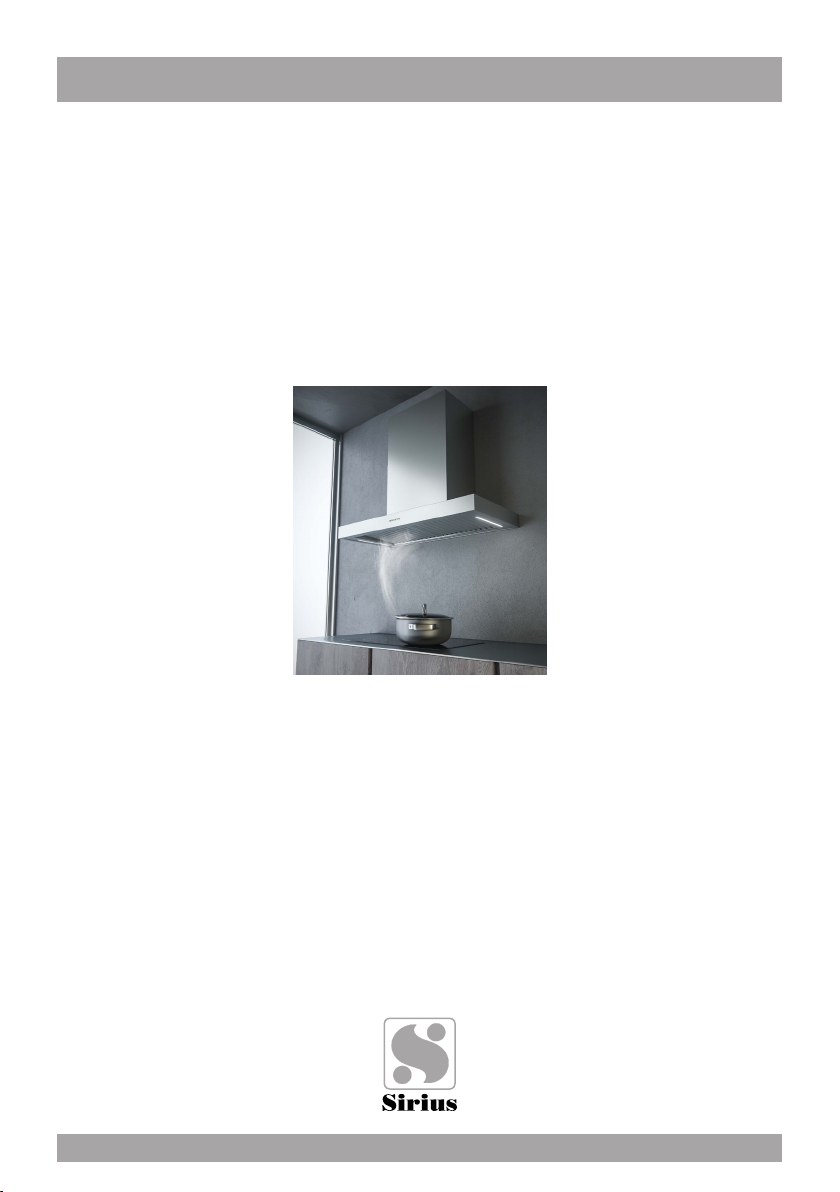
WALL RANGE HOODS
HOTTES MURALES
Models covered by this instructions:
Notice d’instruction pour les modèles:
SU107
*** BEFORE INSTALLATION ***
ENSURE THERE IS NO VISIBLE OR HIDDEN DAMAGE SUSTAINED DURING SHIPPING
*** AVANT L’INSTALLATION ***
S’ASSURER QUE LES PRODUITS N’ONT SUBI AUCUN DOMMAGE PENDANT LE TRANSPORT
*** SHIPPING DAMAGE ***
MUST BE REPORTED WITHIN 5 DAYS OF RECEIPT
*** DOMMAGES DE TRANSPORT ***
DOIVENT ÊTRE NOTIFIÉS DANS LES 5 JOURS SUIVANT LA RÉCEPTION
Page 2

WARNING
Thank you for purchasing a Sirius Range Hood.
Please read all the instructions in this manual before
installing the appliance.
Save these instructions for future reference.
Only use this appliance as an exhaust ventilation system for the removal of cooking vapors. DO NOT use to expel ammable substances or any other materials
or vapors.
The installation procedures in this manual are intended for qualied installers, service technicians or persons with similar qualied background.
DO NOT attempt to install this appliance yourself.
Ensure that electrical power is turned off at source before commencing installation.
All electrical wiring must be properly installed, insulated and grounded and conform
to all applicable codes and standards.
Make sure all existing duct work is clean of grease build up, or duct work should be
replaced, if necessary, to avoid the possibility of a grease re. Check all joints on
ductwork to ensure proper connection and all joints should be properly taped. Be
careful when cutting through ceilings or walls not to damage any hidden pipes or
electrical wiring. Ensure your kitchen has sufcient air return vents to replace the
exhausted air.
Fan ducts should always be vented to the outside of your home and never into
spaces within walls, ceilings, lofts or attics. Only use rigid, smooth steel for ducting.
The exhaust point of the blower requires a 6” round or 8” connection.
2
Page 3
TABLE OF CONTENTS
BEFORE YOU BEGIN 4
DUCTING
External venting Requirements 4
ELECTRICAL
Electrical Supply 5
INSTALLATION
Positioning the Range Hood 6
Marking the Fixing Holes for the Range Hood 6
Fixing the Main Support Bracket 6
Hanging the Range Hood 7
Connecting Electricity and Ducting 7
Connecting Chimneys 9
Re-Circulating Requirements 9
OPERATING PROCEDURES
General Advice 10
Functions 10
MAINTENANCE
Cleaning the Filter 11
Cleaning the Hood 11
Substitution of the LED bar 11
WARRANTY SERVICE 12
3
Page 4
BEFORE YOU BEGIN
The manufacturer declines all responsibility
in the event of failure to observe the instructions given here for installation, maintenance and suitable operation of the product. The
manufacturer further declines all responsibility for injury due to negligence and the warranty of the unit automatically expires due
to improper maintenance and/or installation.
DUCTING
(Not applicable if the range hood is used in
re-circulating mode).
WARNING: Do not vent this appliance into
any other ductwork, spaces between walls,
ceilings, attics, garages or any other conned space.
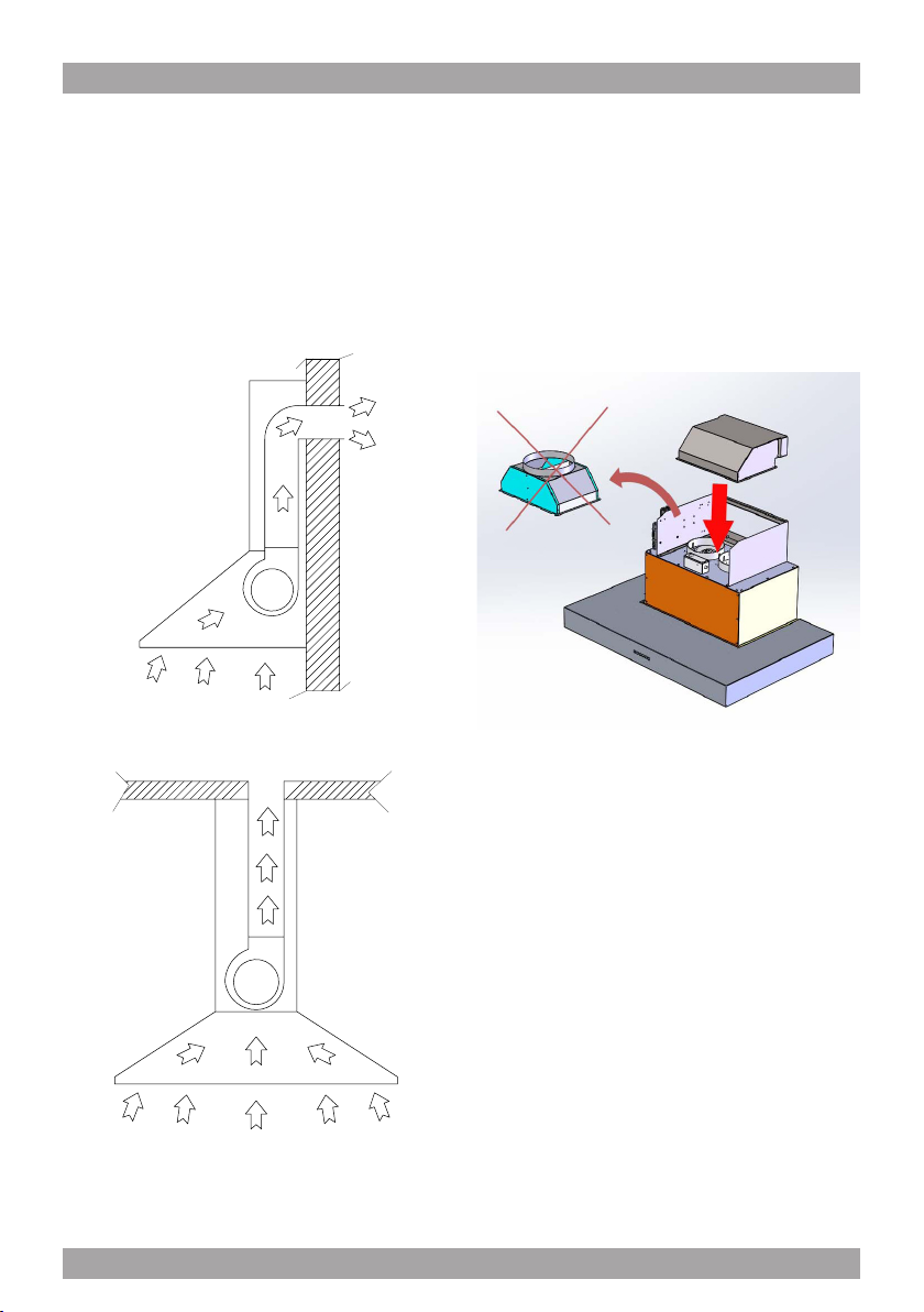
External Venting Requirements.
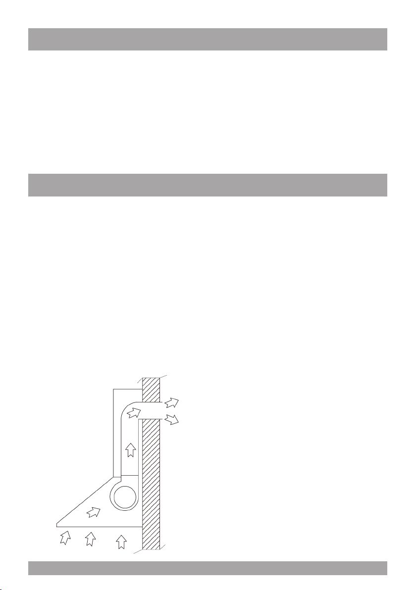
When planning new ductwork, always look
for the most direct route to the outside. Venting can be done through the roof or directly
through the back outside wall. (See Figure
1). Recommanded 18” from the top of the
hood to the rst elbow.
BEFORE YOU BEGIN: It is advisable to
test run the range hood before installation.
BEFORE STARTING – please read this
entire document and ensure you are fully
conversant with the require-ments and limitations. These units weigh approximately
125lbs and therefore require a minimum of
two people to install.
Only use rigid type metal ducting (plastic
ducting is generally not permit-ted by code).
Flexible ducting could restrict airow by up
to 50%. Always fasten connections with sheet metal screws and tape all joints with certied Silver Tape or Duct Tape.
Do not use screws to fasten ductwork to
the hood, only use tape as the screws will
stop the dampers from opening and your
hood will not work. This hood requires 8’’ for
the models with 2 motors. You can increase
the duct size of the duct run but never decrease it.
Use the shortest and most direct route possible. Always, wherever reduce the number
of transitions and turns with as few sharp
angles as possible.
g. 1
4
Two staggered 45 degree angles are better
than one 90 degree. Make these turns as far
away from the motor exhaust as possible,
with as much space between each bend as
possible.
Page 5
* Gas range or gas cook top recommanded
8”.
The ducting connection to the hood must
be in line with the central vertical axis of the
range hood 1” away from the back wall on
which the hood is to be mounted. The 1” is
important to enable the ceiling bracket (as
shown in Figure 2) to pass behind the ductwork servicing the range hood.
g. 2
ELECTRICAL
Range hoods may interrupt the proper ow of
combustion gases from replaces, gas furnaces and gas water heaters.
To minimize the risk of drawing these lethal
gases back into the home, please follow the
heating equipment manufacturers safety
standards and guidelines carefully.
Refer to NFPA and ASHRAE for additional
information.
WARNING: All electrical work must be
performed by a qualied electrician.
Please ensure that the appropriate electrical
codes or prevailing local building codes and
ordinances are adhered to.
Ensure that the electricity supply is disconnected at source. Do not use an extension
cord or adapter plug with this appliance.
This appliance must be grounded. Connect
to a properly grounded branch circuit, protected by a 15 amp circuit breaker.
Electrical Supply.
This range hood requires a 120V, 60Hz supply and draws a maximum of 3 amps. The
electrical supply to the range hood should be
at least 17” from the underside of the installed range hood.
For a typical installation, where the underside of the range hood will be 30” above the
counter top and the counter top is 36” above
the oor level, the electrical supply should be
76” above oor level and no further than 3” to
the right (as you face the wall) of the central
axis of the range hood.
5
Page 6
INSTALLATION
Positioning the Range Hood.
Determine the center point of the range hood.
This is generally the center of the range. Make
a mark on the wall a minimum of 25” above
the top of an electric range. If the range is gas,
the ideal minimum should be 30”.Using a spirit
level, draw a perfectly vertical line, starting at
the center mark, right up to the ceiling or the
highest point to where the hood will extend.
This is the central axis for the range hood.
Draw a horizontal line fractionally above where the bottom of the range hood will be positioned. This is the underside of the range hood.
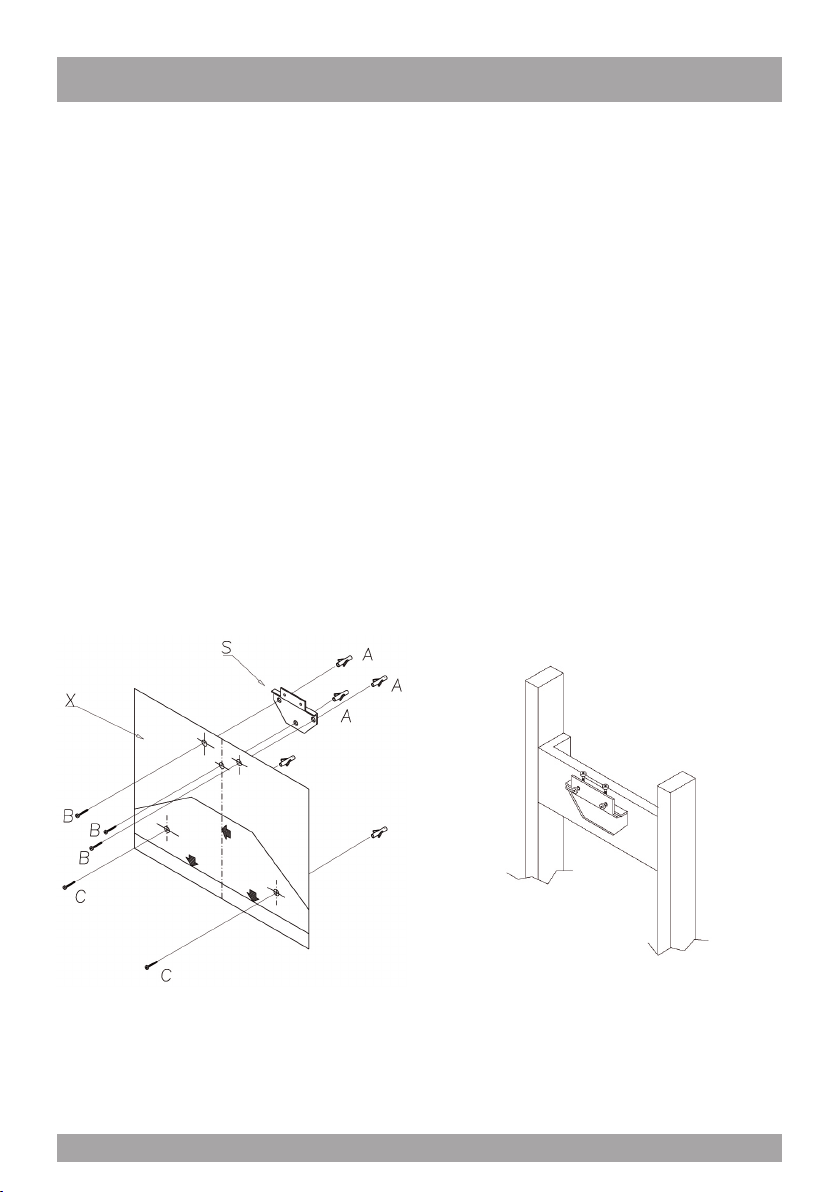
Marking the Fixing Holes for the Range
Hood.
Find the marking template provided called
the “Assembly Scheme”. Place the template
against the wall. Align the horizontal line on
the wall with the horizontal line on the template (indicated by two heavy arrows). Now
align the vertical line on the wall with the
“Central Axis” line on the template.
Using a sharp object, mark the wall through
the template at the center point of the three
holes. Lower down on the template, you will
see three sets of two holes. Only two of these
holes refer to your model. Check which model you have and, using a sharp object, mark
the two correct holes. These holes are used
to anchor the range hood horizontally from inside the hood once it has been hung from the
main bracket. Remove the template.
Fixing the Main Support Bracket
(CAUTION: Do not drill through any utilities inside the wall).
If the range hood will be xed to drywall we
strongly recommend that you discard the wall
plugs and screws supplied. These anchors are
only suitable for brick/masonry applications. We
suggest the use of a more appropriate anchor
system specically designed for drywall applications. Wherever possible, it is advisable to place
blocking between the studs, behind the drywall,
to attach the support bracket to, (refer to Figure 4).
g. 3
Gently tape the template to the wall making
sure it has no creases or folds (use a tape
that will not damage the wall nish). There
are three hole positions shown for the wall
bracket.
6
g. 4
Drill the appropriate size holes at the marks
made earlier and x the Support Bracket (“S”)
securely to the wall. Ensure that any wall anchors have been tted into the lower two holes, as the range hood will cover these holes
once hung on the Support Bracket (“S”).
Page 7
Hanging the Range Hood.
Prepare the range hood for installation.
Remove all lters to ensure they do not get
damaged during the installation process.
Hang the range hood on the bracket “S” (refer to Figure 6).
g. 6
The bracket xed onto the back of the range
hood will drop into the channel on the top
of bracket “S” on the wall. Ensure the hood
is securely engaged into the support brackt
the range hood must clip in behind the extended lip on the Support Bracket (“S”).
These screws are also used to make minor
adjustments to the levelling of the range
hood. Ensure the hood is level. Locate the
two holes “C” inside the housing of the range hood and secure the range hood to the
wall once the range hood is perfectly level
and vertical. (refer to Figure 3).
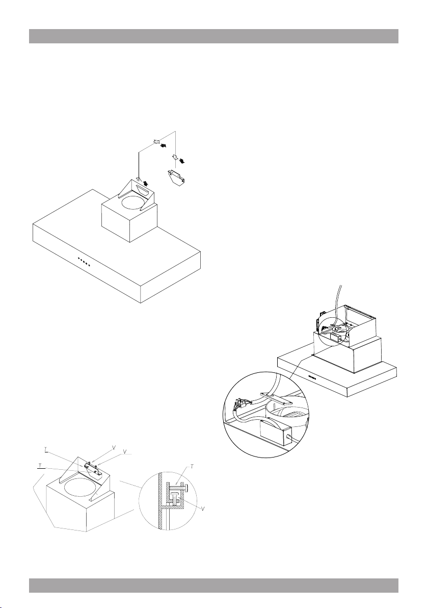
Connecting Electricity and Ducting.
Please refer to the Electrical Supply section
on page 5 for the required location of the
electrical supply.
CAUTION: Make sure the power is turned
off at source. Make electrical connections
(refer to Figure 8).
Ensure that the plastic aps at the exhaust
outlet for the fan move freely and have not
become jammed or stuck.
“Lock” the range hood onto the “S” bracket
using the four machine screws supplied (refer to Figure 7).
g. 7
g. 8
7
Page 8
Connect the appropriate length of ducting to
the fan exhaust point and join up with the
ducting to the exte-rior.
Do not x the ducting to the range hood
exhaust outlet with screws-use duct
tape. Use duct tape on all joints.
Figure 9 shows venting directly through the
wall. Venting up and through the ceiling to
the exte-rior is also possible racommended
to have 18” from the top of the hood to the
rst elbow.
g. 9
The air outlet of the product is oriented upwards: in the case that one prefers the air
outlet towards the rear side of the appliance,
it is only necessary to replace the air release
piece with the other one supplied with the
appliance.
g. 10
8
Page 9

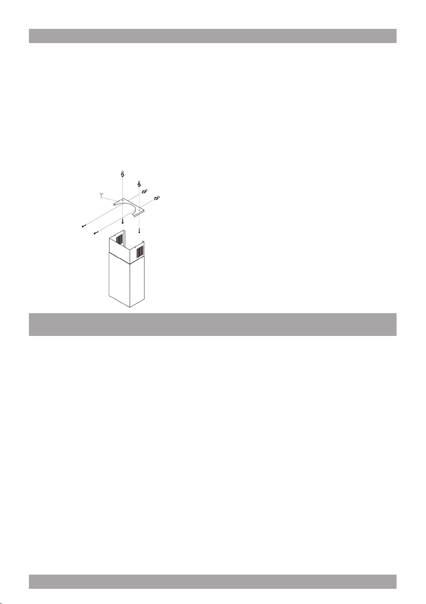
Connecting Chimneys
Remove the protective covering from the
decorative chimney and carefully slide the
sections together. Do not remove the tape
strips from inside the chimney as this protects the telescoping chimney-piece from
scratching. Holding the two chimney sections together carefully position them over
the ductwork and wiring. Position the upper
chimney so that it can be xed via the holes
on the side of the ‘Y” bracket on the ceiling
(refer to Figure 11).
The carbon lter (supplied separately) that
absorbs odors is installed behind the aluminium grease lter (refer to Fig 14).
g. 12
g. 11
Re-Circulating Requirements.
If the unit is to be used in the re-circulating
mode, t the carbon lter after the installation is complete t the deector with the
screws supplied to the upper telescope
chimney. There are holes in the back upper
edge of the decorative chimney for this purpose. A short length of ducting is connected
between the exhaust outlet on the fan and
the deector to direct the air back into the
kitchen through the vents at the top of the
upper decorative chimney.
g. 13
g. 14
9
Page 10

OPERATING PROCEDURES
Read all the instructions before operating
the appliance. Save these instructions for
future reference.
General Advice.
Ensure that the grease lters are in place.
Without these components, operating blowers could catch on to hair, ngers and loose clothing. Keep fan, lters and surfaces
clean of grease and fat. Always turn hood
fan ON when cooking. NEVER leave cooking unattended.
NEVER dispose cigarette ashes, ignitable
substances or any foreign objects into blowers.
Cooking that generates ame is not recommended as this hood is equipped with a
thermal overload that will shut down the motor if it senses excessive heat. When frying,
oil in the pan can easily overheat and ignite. Heat oil slowly in an appropriately sized
pot (covering the entire burner) to reduce
the risk of boiling over and burning.
In the event of a range top grease re, observe the following:
Switch OFF the range hood. Turn off the
cook top then smother ames with a close
tting lid, cookie sheet or other metal tray. If
the ames do not go out immediately.
FUNCTION
“Manual touch buttons Fig.15”.
A: Light ON/OFF button
B: Blower Speed 1 (low) or OFF
C: Blower Speed 2 (medium)
D: Blower Speed 3 (high)
E: Blower Speed 4 (intensive)
F: 10 Minute Timer
g. 15
The products are endowed with an electronic
device which allows the automatic switching
off after 4 hours working from the last operation.
SU Models only: Filter requires washing indicator After 30 hours of use, all the buttons
will light up to remind you that the grease lter should be cleaned. Follow the instructions
for cleaning lters in this booklet. Once the
grease lters have been cleaned and replaced, reset by pressing the timer button (F).
EVACUATE AND CALL THE FIRE DEPARTMENT.
Never pick up a aming pan – you may be
burned. DO NOT USE WATER including
wet dishcloths or towels, as a violent steam
explosion may occur.
10
Do not rely solely on this indicator - generally,
the grease lter should be washed on a regular basis to avoid grease lter res.
The blower should be turned on for approximately 5 minutes before cooking in order
to establish air currents upward through the
hood.
Use the low speeds for normal use and the
higher speeds for strong odors and fumes.
Page 11

MAINTENANCE
The range hood should provide many years of trouble free use provided it is properly
maintained. Be sure the lights are cool before
cleaning the hood - they are halogen and become extremely hot.
Cleaning the Filter.
The aluminium mesh lters should be washed by hand or in the dishwasher as required. Damaged and worn lters must be replaced immediately. (Do not operate blower
when lters have been removed). Allow lters
to dry before replacing them, otherwise water
will be drawn into the blower.
If a carbon lter has been tted, this must be
replaced every 6 months as a minimum, depending on usage and type of cooking that is
performed.
It is suggested that a spare set of carbon lters is kept on hand. These can be ordered
from the supplier of your range hood.
Cleaning the Hood
The outside and interior of your hood should
be wiped regularly with a clean, damp cloth
and mild household dish detergent or degreaser.
Do not use abrasive cleaning agents as these will destroy the brushed nish.
Substitution of the LED bar:
Using an appropriate tool, remove the LED
bar from its seat (refer to Fig. 21), disconnect
it electronically using the appropriate connector then substitute it with a LED bar with
same characteristics.
g. 21
Use a good quality non-abrasive foaming
type stainless steel cleaner for exterior surfaces.
Follow the manufacturers directions. Generally the foam is sprayed onto a clean dry
cloth and then applied to the stainless steel.
Allow the foam to react on the surface for a
few minutes and then wipe with a clean dry
cloth.
On the surfaces that are exposed directly to
heat from the cook-top, it is advisable to clean these regularly to avoid the deposits from
becoming baked on.
11
Page 12

YOU MUST REGISTER THE PURCHASE OF YOUR PRODUCT ON LINE AT HYPERLINK
“http://www.siriuscappe.com/canada/warranty.htm” TO CONVALIDATE YOUR WARRANTY.
YOU CAN FIND THE DATA OF YOUR HOODS ON A LABEL INSIDE THE HOOD. JUST REMOVE
THE GREASE FILTER TO READ IT.
To qualify for warranty service, you must notify Sirius After sale service at the email address
stated below or call toll free in Canada 1-800-463-2566 and provide the model number, description of the fault or defect and original date of purchase. Sirius reserves the right to request proof of original purchase. Sirius will at its sole option and discretion replace products
that arrive damaged through shipping, provided shipping damage is reported as stated above
within 5 business days of receipt of the shipped product or products.
ONE YEAR PARTS & SERVICE REPAIR WARRANTY:
During the rst year from date of original purchase, Sirius will, at its option, repair or replace, without
charge, any product or part which is found to be defective under normal use and service.
WHO IS COVERED:
Sirius Range Hoods warrants to the original consumer purchaser of its products that such products will
be free from defects in materials and workmanship for a period of one year from the original date of purchase. There are no other warranties, express or implied, including, but not limited to, implied warranties
of merchantability or tness for a particular purpose or application.
WHAT IS NOT COVERED:
This warranty does not extend to lters, lamps, batteries, ducts and ductwork components. This warranty does not cover normal maintenance and service or products or parts which have been subject to
misuse, negligence, accident, improper maintenance or repair, faulty installation or installation contrary
to recommended installation instructions. The warranty on glass screens is limited to manufacturing
defects only and expressly excludes cracks and breakages as a result of faulty installation.
WARRANTY SERVICE
Labor and
associated costs associated directly with removal and re-installation are expressly excluded.
The duration of any implied warranty is limited to the one year period as specied for the express warranty. Some states and provinces do not allow limitation on how long an implied warranty lasts, so the
above limitation may not apply to you.
For any service request please contact:
Sirius after sale service
Telephone (toll free):1-800-463-2566.
Sirius S.P.A.
Zona industriale Berbentina 6/A
60041 SASSOFERRATO (AN)
ITALY
Register Online! www.siriuscappe.com/canada/warranty.htm
Page 13

INSTRUCTIONS IMPORTANTES
POUR LA SÉCURITÉ
Merci d’avoir choisi une Hotte de Cuisine Sirius.
Veuillez lire attentivement toutes les instructions avant
l’installation et l’utilisation de l’appareil.
Conservez ces instructions an de pouvoir les consulter
au besoin.
Cet appareil est destiné à la ventilation générale seulement. NE L’UTILISEZ PAS
pour évacuer des vapeurs ou des substances dangereuses ou explosives.
Conez l’installation et les réparations uniquement à un professionnel, conformément aux normes de sécurité en vigueur.
N’ESSAYEZ PAS d’installer cet appareil par vous-même.
Avant l’installation veillez que l’appareil soit hors tension.
Tout le câblage électrique doit être correctement installé, isolé de mise à la terre
conformément aux codes et aux normes applicables.
Assurez-vous que les conduits d’évacuation sont propres et libres d’accumulation
de graisses ou remplacez les conduits pour éviter de provoquer un incendie.
Vériez que tous les joints du conduit sont bien xés et scellés. Faites attention
lors des travaux de maçonnerie de ne pas endommager des tuyaux ou câbles
électriques. Assurez-vous que votre cuisine est équipée de bouches de ventilation
qui évacuent l’air vicié.
Le conduit de ventilation doit toujours terminer à l’extérieur et jamais dans des
espaces clos, plafonds ou greniers. Pour le conduit utilisez seulement des éléments rigides en acier lisse. La sortie de la soufante nécessite d’un conduit rond
de 6”. Ou Huit pouces (ou 8’’).
13
Page 14

TABLE DES MATIÈRES
AVANT DE COMMENCER 15
CONDUIT
Version évacuation extérieure 15
ÉLECTRICITÉ
Alimentation Électrique 16
INSTALLATION
Positionnement de la Hotte 17
Perçage du Mur pour le Positionnement de la Hotte 17
Fixation Étrier de Support Principal 17
Accrochage de la Hotte 18
Branchement Électrique et Conduit 18
Raccordement de la Cheminée 20
Mode Recyclage 20
OPERATING PROCEDURES
Recommandations Générales 21
Fonctions 21
ENTRETIEN
Nettoyage des Filtres 22
Nettoyage de la Hotte 22
Replacement de la barre LED 22
SERVICE DE GARANTIE 24
14
Page 15

AVANT DE COMMENCER
Le fabricant décline toute responsabilité
en cas de dommages causés par un non
respect des instructions d’installation, d’utilisation et d’entretien contenues dans cette
notice. Le fabricant décline toute responsabilité causée par négligence et la garantie
cesse automatiquement en cas de mauvais
entretien et/ou installation du produit.
CONDUIT
(Ne s’applique pas si la hotte est en mode
Recyclage).
REMARQUE : Ne branchez jamais ce produit à un autre conduit d’évacuation, des
espaces entre deux murs, plafonds, greniers, garages ou espaces clos.
Version évacuation extérieure.
Lors du montage du conduit d’évacuation,
cherchez la voie la plus directe vers l’extérieur. Le conduit peut évacuer l’air par le
toit ou directement par le mur extérieur. (Voir
Fig. 1). Il est recommandé une distance de
18 pouces, à partir du sommet de la hotte
jusqu’au premier coude.
AVANT DE COMMENCER : On conseille
de vérier le fonctionnement de la hotte
avant son installation.
AVANT DE COMMENCER - Lisez attentivement cette notice an d’avoir les connaissances requises pour utiliser ce produit.
Ce produit pèse env. 125lbs et nécessite
donc un minimum de deux personnes pour
son installation.
Utilisez seulement des tuyaux rigides en
métal (les tuyaux en plastiques sont interdits
par le code).
Les conduits exibles limitent le ux d’air du
50%. Fixez toujours les raccords avec des
vis en tôle et isolez tous les joints avec du
ruban adhésif métallique (ou pour conduit).
N’utilisez pas des vis pour xer le conduit à la hotte; utilisez uniquement du ruban
adhésif, du moment que les vis peuvent empêcher l’ouverture des clapets anti retour et
en ce cas la hotte ne fonctionnera pas.
Cette hotte nécessite d’un conduit d’évacuation de 8’’ pour les modèles avec 2 moteurs. Il est possible d’utiliser un conduit
plus grand, mais pas un plus petit.
g. 1
Optez pour la voie la plus courte et la plus
directe. Evitez, si possible, le nombre des
raccords et des coudes.
Il est préférable d’utiliser deux coudes de
45° plutôt qu’un coude de 90°. Positionnez
les coudes loin de l’échappement du moteur
et évitez de les positionner trop prêt les uns
des autres.
15
Page 16

* Gaz fourneau ou gaz cuisinière recommandé: 8 pouces.
Le raccordement du conduit à la hotte doit
être en ligne avec l’axe centrale verticale de
la hotte de 1” et loin du mur postérieur sur
lequel la hotte sera positionnée. La mesure
1” est importante pour permettre au support
de plafond (voir Fig. 2) de passer derrière le
conduit de la hotte.
g. 2
ÉLECTRICITÉ
Les hottes peuvent empêcher la bonne évacuation des fumées des cheminées, des
fours et des chauffe-bains à gaz.
An de minimiser le risque que ces gaz mortels peuvent retourner dans la maison, observez les normes de sécurité et les directives
en vigueur.
Consultez les normes NFPA et ASHRAE
pour plus d’informations.
ATTENTION : Tous les travaux électriques doivent être effectués par un électricien qualié.
An d’assurer la qualité des travaux de construction et d’électricité observez les normes en vigueur.
Assurez-vous que l’alimentation électrique
est coupée. Evitez d’utiliser une rallonge ou
un adaptateur pendant cette opération.
Cet appareil doit être mis à la terre et le circuit doit être protégé par un disjoncteur de
15 amp.
16
Alimentation Électrique.
Cet appareil nécessite 120V/60Hz, une alimentation de 3amp. L’alimentation électrique
se doit trouver au moins à 17” du dessous de
la hotte installée.
Pour une installation type, où la distance entre la partie inférieure de la hotte et la surface
de la table de travail est de 30” et la distance
entre la table de travail et le sol de 36”, l’alimentation électrique se doit trouvée à 76” du
sol et pas plus de 3” à droite (en regardant le
mur) par rapport à l’axe centrale de la hotte.
Page 17

INSTALLATION
Positionnement de la Hotte.
Déterminez le centre de la hotte. Marquez
d’une croix sur le mur la hauteur de 25” si
votre table de cuisson est électrique et une
hauteur minimale de 30” si votre table de
cuisson est à gaz. En utilisant un niveau à
bulle tracez une ligne parfaitement verticale,
à partir du centre vers le plafond ou vers le
point le plus élevé où positionner votre hotte. C’est l’axe central de la hotte. Tracez une
ligne horizontale où le bas de la hotte sera
positionné. Il s’agit de la partie inférieure de
la hotte.
Perçage du Mur pour le Positionnement
de la Hotte:
Prenez le gabarit de perçage fourni, appelé
« Schéma de Montage ». Placez le gabarit
contre le mur. Alignez la ligne horizontale du
mur avec la ligne horizontale du gabarit (indiquée par les deux èches). Maintenant alignez la ligne verticale du mur avec la ligne
de l’ « axe central » du gabarit.
Utilisez un outil pointu, marquez le mur par le
gabarit au point milieu des trois trous. Au bas
du gabarit, il y a trois séries de deux trous. Seulement deux de ces trous se réfèrent à votre
modèle. Vériez quel modèle vous avez et, toujours en utilisant un outil pointu, marquez les
deux trous justes. Ces trous servent pour l’ancrage de la hotte horizontalement par l’intérieur
de la hotte, une fois quelle a été positionnée sur
le support principal. Retiré le gabarit.
Fixation Étrier de Support Principal
(ATTENTION de ne pas endommager les
conduites).
Si vous xez la hotte sur du plaque de plâtre,
on vous conseille vivement d’enlever/éliminer
les chevilles et les vis fournies. Ces ancrages
ne conviennent que pour une utilisation avec briques/maçonnerie. On vous conseille d’utiliser un
système d’ancrage plus adapté et spéciquement conçu pour la plaque de plâtre. Autant que
possible, il est préférable d’utiliser des blocages
entre les poutres, derrière la plaque de plâtre,
pour y xer l’étrier de support (voir Fig. 4).
g. 3
Appliquez doucement le gabarit sur le mur
en vous assurant qu’il est lisse et sans plis
(utilisez un ruban adhésif qui n’endommage
pas la nition du mur). Il y a trois positions de
perçage pour le support mural.
g. 4
Percez le mur aux endroits précédemment
marqués et xez bien l’étrier au mur. Assurezvous que les chevilles ont été insérées dans les
deux trous inférieurs, ainsi la hotte les couvrira
une fois qu’elle est positionnée sur l’étrier (“S”).
17
Page 18

Accrochage de la Hotte.
Préparez la hotte pour son accrochage. Enlevez les ltres pour ne pas les endommager pendant l’installation. Accrochez la hotte
sur l’étrier de support “S” (voir Fig. 6).
g. 6
L’étrier xé à la partie postérieure de la
hotte se glisse dans la rainure de la partie
supérieure de l’étrier de support “S” du mur.
Assurez-vous que la hotte est correctement
insérée dans l’étrier de support - la hotte
doit s’accrocher derrière le bord étendu de
l’Étrier de Support (“S”).
Ces vis sont également utilisées pour apporter des modications mineures au nivellement de la hotte. Assurez-vous que la
hotte est à niveau. Localisez les deux trous
pour vis “C” à l’intérieure de la hotte et xezla au mur en vous assurant qu’elle est parfaitement à niveau (voir Fig. 3).
Branchement Électrique et Conduit.
Faites référence au paragraphe Alimentation Électrique à la page 5 pour l’endroit où
effectuer le branchement.
ATTENTION : Assurez-vous que l’alimentation est coupée. Effectuez le raccordement
électrique (voir Fig. 8).
Veillez à ce que les volets en plastiques de
la sortie des fumées se bougent librement et
qu’ils ne sont pas bloqués ou coincés.
Fixez la hotte à l’étrier “S” avec les 4 vis à
métaux fournies (voir Fig. 7).
g. 7
18
g. 8
Page 19

Raccordez le conduit de longueur appropriée à la sortie d’air du ventilateur et puis
au conduit qui porte à l’extérieur.
La gure 9 montre l’évacuation à travers le
mur. Une évacuation par le plafond est également possible. Il est recommandé une distance de 18 pouces, à partir du sommet de
la hotte jusqu’au premier coude.
g. 9
Ne xez jamais le conduit à la sortie
d’évacuation de la hotte avec des vis utilisez uniquement du ruban adhésif.
Utilisez uniquement du ruban adhésif pour
tous les joints.
La sortie de l’air du produit est dirigée vers
l’haut: dans le cas où on préfère une sortie
vers la partie postérieure de la hotte, il faut
seulement remplacer le raccord par l’autre,
fourni dans l’équipement.
g. 10
19
Page 20

Raccordement de la Cheminée.
Enlevez la protection de la cheminée décorative et faites glisser soigneusement les sections ensemble. N’enlevez pas les bandes
adhésives à l’intérieur de la cheminée car
ils protègent le télescope contre les rayures.
Tenez les deux sections de la cheminée et
positionnez-les sur le conduit et le câblage.
Positionnez la cheminée supérieure de façon
qu’elle puisse être xée par les trous pour vis
du support “Y” au plafond (voir Fig. 11).
g. 11
Le ltre à charbon (fourni séparément) qui
absorbe les odeurs, se trouve derrière le
ltre à graisse en aluminium (voir Fig. 14).
g. 12
Mode Recyclage.
Si vous utilisez l’appareil en mode recyclage, insérez les ltres à charbon une fois l’installation complétée (voir Fig. 12).
Fixez le déecteur (voir Fig. 13) avec les
vis à la partie supérieure du télescope de la
cheminée. A ce propos, il y à des trous pour
vis sur l’arrière de la cheminée décorative.
Un conduit court se trouve entre la sortie
d’évacuation et le déecteur pour diriger l’air
dans la cuisine à travers des orices d’air
qui se trouvent sur la partie supérieure de la
cheminée décorative.
20
g. 13
g. 14
Page 21

OPERATING PROCEDURES
Lisez attentivement toutes les instructions
avant cette opération. Conservez ces instructions an de pouvoir les consulter au besoin.
Recommandations Générales.
Assurez-vous que les ltres sont en place.
Sans ces ltres, l’appareil peut aspirer vos
cheveux, doigts ou vêtements.
Maintenez propre de graisse le ventilateur,
les ltres et les surfaces. Mettez TOUJOURS en marche la hotte pendant la cuisson. Ne laissez JAMAIS des aliments cuire
sans surveillance.
Ne jetez JAMAIS les cendres de cigarettes,
des substances inammables ou autres
objets étrangers dans le ventilateur.
Evitez une cuisson qui peut générer des
ammes, car la hotte est équipée d’un
détecteur thermique qui arrête le moteur à
une chaleur excessive.
Lorsque vous faites des fritures, l’huile
dans la poêle peut facilement se surchauffer et s’enammer. Faites chauffer l’huile
lentement dans une casserole de taille appropriée (couvrant entièrement le brûleur)
réduisant ainsi le risque de la faire déborder
et s’enammer.
Dans le cas où l’huile s’enamme, observez
ce qui suit:
Eteignez la hotte. Eteignez la table de cuisson et étouffez les ammes avec un couvercle hermétique, une tôle à biscuits ou autre
plateau métallique. Si les ammes ne s’éteignent pas immédiatement.
SORTEZ ET APPELEZ LES POMPIERS.
Ne ramassez jamais une casserole enammée – vous pouvez vous brûler. N’UTILISEZ
JAMAIS DE L’EAU, y compris des serviettes
ou lavettes mouillées, car une explosion
peut se produire.
FONCTIONS
“Touches Sensitives Fig.15”.
A: Touche lumière ON/OFF
B: Vitesse ventilateur 1 (réduite) ou OFF
C: Vitesse ventilateur 2 (moyenne)
D: Vitesse ventilateur 3 (élevée)
E: Vitesse ventilateur 4 (intensive)
F: Minuterie 10 min
g. 15
Les produits sont doté d’un appareil électronique, qui permet l’éteindre automatique depuis 4 heures d’activité de la dernière opération.
Seulement pour modèle SU: Après 30 heures de fonctionnement de la hotte, tous les
voyants clignotent pour vous rappeler que les
ltres à graisse doivent être nettoyés. Suivez
les indications pour le nettoyage dans cette
notice. Une fois nettoyés et remplacés les ltres, réinitialisez en appuyant sur la touche
Timer (F).
Ne comptez pas uniquement sur cet indicateur. Généralement, les ltres à graisse doivent être nettoyés régulièrement, an d’éviter
toute incendie de graisse.
Allumez la hotte env. 5 minutes avant la cuisson, an d’établir des courants d’air vers le
haut et à travers la hotte. Utilisez les vitesses
basses pour une utilisation normale et les vitesses élevées pour les odeurs fortes et les
fumées.
21
Page 22

ENTRETIEN
Un entretien soigné garantit un bon fonctionnement et un bon rendement dans le temps.
Assurez-vous que les ampoules sont froides
avant de nettoyez la hotte - les ampoules halogènes deviennent très chaudes.
Nettoyage des Filtres.
Lavez les ltres à maille en aluminium à la
main ou au lave-vaisselle. Remplacez immédiatement les ltres usagés ou endommagés. N’utilisez jamais la hotte sans ses
ltres. Avant de replacer les ltres, assurezvous qu’ils sont bien secs pour ne pas endommager le ventilateur.
Remplacez le ltre au moins tous les 6 mois,
selon le type et la fréquence des cuissons.
Nous vous suggérons de garder des ltres
de recharge. Vous pouvez les commandés
auprès le fournisseur de votre hotte.
Nettoyage de la Hotte.
Nettoyez l’intérieur et l’extérieure de la hotte
avec un chiffon propre et du détergent doux.
Utilisez un détergent non abrasif sous forme
de mousse pour les parties en acier.
Lisez les instructions du fabricant.
Replacement de la barre LED :
En utilisant un outil approprié, enlever la barre LED de son siège (faites référence à la
Fig. 21), déconnecter – la électroniquement
en utilisant le connecteur approprié et puis la
replacé avec une barre LED avec les mêmes
caractéristiques.
g. 21
Généralement on conseille de vaporiser le
détergent sur un chiffon propre et de le passer sur les parties en acier inoxydable.
Laissez agir le produit sur la surface pendant
quelques minutes, puis nettoyer avec un chiffon.
Sur les surfaces qui sont exposées directement à la chaleur, on conseille de les nettoyer régulièrement pour éviter des taches
indélébiles.
N’utilisez jamais un produit abrasif qui peut
rayer et endommager l’acier.
22
Page 23

23
Page 24

IL EST NÉCESSAIRE D’ENREGISTRER EN LIGNE L’ACHAT DE VOTRE PRODUIT AU SITE HYPERLINK
http://www. siriuscappe. com/canada/warranty.htm POUR VALIDER LA GARANTIE.
VOUS TROUVEZ LES DONNÉES DE VOTRE HOTTE SUR L’ÉTIQUETTE À L’INTÉRIEUR DE LA
HOTTE. POUR LA LIRE, RETIREZ SIMPLEMENT LE FILTRE A GRAISSE.
Pour bénécier du service de garantie, informez le Service Après Vente Sirius à l’adresse e-
SERVICE DE GARANTIE
mail ci-dessous ou appelez le numéro gratuit CANADA 1-800-463-2566 et fournissez le code
du produit, la description du vice ou du défaut et la date d’achat du produit. Sirius se réserve
le droit de demander une preuve d’achat. Sirius, à sa propre discrétion, remplacera les produits endommagés pendant le transport, à condition que le dommage dû au transport est
signalé comme susmentionné, c’est-à-dire DANS LES 5 JOURS DE TRAVAIL APRÈS RÉCEPTION du produit ou des produits expédiés.
GARANTIE D’UN AN POUR LE SERVICE DE RÉPARATION:
Pendant la première année dès la date d’achat de votre produit, Sirius, à sa discrétion, réparera ou
remplacera gratuitement tout produit ou pièce qui s’avère défectueux dans des conditions normales
d’utilisation et d’entretient.
QUI EST COUVERT PAR LA GARANTIE:
Sirius Range Hoods garantit à l’acheteur original que tous ses produits commerciaux sont libres de tout
défaut de matériel et de fabrication, pour la durée d’un an à partir de la date d’achat. Il n’existe aucune
autre garantie, expresse ou tacite, y compris mais sans s’y limiter, aucune garantie de qualité commerciale ou d’adaptation à une utilisation particulière.
QU’EST-CE QUI N’EST PAS COUVERT PAR LA GARANTIE:
Cette garantie ne couvre pas les ltres, lampes, batteries, tuyaux et composants du conduit. Cette
garantie ne couvre pas l’entretien normal et le service après-vente technique standard, produits ou
pièces endommagées résultant d’une mauvaise utilisation, acte de négligence, ac- cident, entretien ou
réparation impropre, installation erronée ou installation contraire aux in- structions d’installation recommandées. La garantie sur les pièces/écrans en verre est limitée uniquement aux vices de fabrication et
exclut expressément toute rayure ou rupture résultant d’une mauvaise utilisation. Les frais de la maind’oeuvre et ceux qui sont directement associés au démontage et au remontage sont expressément
exclus.
La durée de toute garantie implicite est limitée à un an, ainsi que spécié par la garantie explicite.
Certains états et certaines provinces ne permettent pas de limitations quant à la durée d’une garantie
implicite, par conséquent les limitations ci-dessus peuvent ne pas s’appliquer à vous.
Pour toutes informations merci de contacter :
Sirius service après-vente
Téléphone (gratuit) 1-800-463-2566.
Sirius S.P.A.
Zona industriale Berbentina 6/A
60041 SASSOFERRATO (AN)
ITALY
Register Online! www.siriuscappe.com/canada/warranty.htm
90001070021 - GM 07/17
 Loading...