

Page 1

User Guide
Sportster 5
Satellite Radi o
Page 2

Page 3

Congratulations on the Purchase of your new SIRIUS Sportster
SP5 Plug-n-Play Radio
Your new SIRIUS Sportst er™ SP5 Plug-n-Play Radio lets you enjoy SIRIUS® Satellite
Radio’s digital ente rtainment anywhere you’ve installed the SUPH1C SIRIUS Universal
Plug and Play Home Kit, SUPV1C SIRIU S Universal Plug and Play Vehicle K it, or the
SUBX1C SIRIUS Plug and Play Universal Boombox (each sold separately). Use this
manual to familiarize yourself with all of SIRIUS Sportster’s features and ca pabilities. F or
the latest information about this and other SIRIUS Sportster products and accessor ies,
visit http://siriuscan ada.ca.
Page 4

Table of Contents
TABLE OF CONTENTS . . . . . . . . . . . . . . . . . . . . . . . . . . . 4
WARNING AND SAFETY INFORMATION . . . . . . . . . . . . . . . . . . . 6
Industry Canada (IC) Statement . . . . . . . . . . . . . . . . . . . . . . 6
Canadian Compliance . . . . . . . . . . . . . . . . . . . . . . . . . . 7
General Precautions . . . . . . . . . . . . . . . . . . . . . . . . . . . 7
Warnings . . . . . . . . . . . . . . . . . . . . . . . . . . . . . . . 8
COPYRIGHTS & TRADEMARKS . . . . . . . . . . . . . . . . . . . . . 10
PACKAGE CONTENTS . . . . . . . . . . . . . . . . . . . . . . . . . . 11
INSTALLATION . . . . . . . . . . . . . . . . . . . . . . . . . . . . . 14
Installing the Vehicle Dock . . . . . . . . . . . . . . . . . . . . . . . . 14
Installing the Magnetic Antenna . . . . . . . . . . . . . . . . . . . . . . 21
Antenna Mounting . . . . . . . . . . . . . . . . . . . . . . . . . . 22
Cable Routing . . . . . . . . . . . . . . . . . . . . . . . . . . . . 24
Tips . . . . . . . . . . . . . . . . . . . . . . . . . . . . . . . . 32
Connecting the Cigarette Lighter Adapter . . . . . . . . . . . . . . . . . . 37
Docking Your SIRIUS Radio . . . . . . . . . . . . . . . . . . . . . . . . 37
Connecting Your SIRIUS Radio to Your Vehicle’s Audio System . . . . . . . . . 38
Subscribing to the SIRIUS Service . . . . . . . . . . . . . . . . . . . . . 44
CONTROLS . . . . . . . . . . . . . . . . . . . . . . . . . . . . . . 45
SIRIUS Sportster SP5 Front Panel . . . . . . . . . . . . . . . . . . . . . 45
Remote Control Buttons . . . . . . . . . . . . . . . . . . . . . . . . . 48
Vehicle Dock Reference Guide . . . . . . . . . . . . . . . . . . . . . . . 51
OPERATION . . . . . . . . . . . . . . . . . . . . . . . . . . . . . . 52
Display Screen Information . . . . . . . . . . . . . . . . . . . . . . . . 52
Navigating Menus and Lists . . . . . . . . . . . . . . . . . . . . . . . . 53
Display (Disp) Button . . . . . . . . . . . . . . . . . . . . . . . . . . . 53
Search Modes (Preset, Category, Channel, Artist, Song Title) . . . . . . . . . . 55
[ Tabl e of Con tent s ]
4
Page 5

Direct Tuning . . . . . . . . . . . . . . . . . . . . . . . . . . . . . . 58
Channel Presets . . . . . . . . . . . . . . . . . . . . . . . . . . . . 58
Jump Button . . . . . . . . . . . . . . . . . . . . . . . . . . . . . . 60
Memory (MEMO) and Song Seek (S-Seek) Functions . . . . . . . . . . . . . . 61
Sports Alert . . . . . . . . . . . . . . . . . . . . . . . . . . . . . 69
Instant Replay . . . . . . . . . . . . . . . . . . . . . . . . . . . . . 70
FM Presets Button . . . . . . . . . . . . . . . . . . . . . . . . . . . 74
MENU OPTIONS . . . . . . . . . . . . . . . . . . . . . . . . . . . . 75
Sirius ID . . . . . . . . . . . . . . . . . . . . . . . . . . . . . . . . 76
Settings . . . . . . . . . . . . . . . . . . . . . . . . . . . . . . . . 77
FM Transmitter . . . . . . . . . . . . . . . . . . . . . . . . . . . . 78
Display Settings . . . . . . . . . . . . . . . . . . . . . . . . . . . 79
S-Seek alert settings . . . . . . . . . . . . . . . . . . . . . . . . . 83
Audio Level . . . . . . . . . . . . . . . . . . . . . . . . . . . . . 84
Channel Preview . . . . . . . . . . . . . . . . . . . . . . . . . . . 85
Factory Default . . . . . . . . . . . . . . . . . . . . . . . . . . . . 86
Parental Control . . . . . . . . . . . . . . . . . . . . . . . . . . . 87
Sports Alerts . . . . . . . . . . . . . . . . . . . . . . . . . . . . 89
Sports Selections . . . . . . . . . . . . . . . . . . . . . . . . . . . 90
NASCAR . . . . . . . . . . . . . . . . . . . . . . . . . . . . . . 90
NFL, NBA, NHL, College football, college basketball . . . . . . . . . . . . . 92
Clock . . . . . . . . . . . . . . . . . . . . . . . . . . . . . . . . 94
Alarm . . . . . . . . . . . . . . . . . . . . . . . . . . . . . . . . 95
Program Alert . . . . . . . . . . . . . . . . . . . . . . . . . . . . 96
Auto Shutdown . . . . . . . . . . . . . . . . . . . . . . . . . . . . 97
Sleep Mode . . . . . . . . . . . . . . . . . . . . . . . . . . . . . 97
Signal Indicator . . . . . . . . . . . . . . . . . . . . . . . . . . . . . 98
SPECIFICATIONS . . . . . . . . . . . . . . . . . . . . . . . . . . . .100
WARRANTY . . . . . . . . . . . . . . . . . . . . . . . . . . . . . . 101
SIRIUS ID . . . . . . . . . . . . . . . . . . . . . . . . . . . . . . . 102
[ Tabl e of Con tent s ]
5
Page 6

Warning and Safety Information
Industry Canada (IC) Statement
Operation is subject to the following two conditions: (1) this device may not cause interference, and (2) this devi ce must accept any interference, including interf erence that
may cause undesired op eration of the device.
To reduc e potential radio interferenc e to other users, the antenna type and its gain
should be so ch osen that the equivalent isotropically radiated power (e.i.r.p.) is not more
than that permitted fo r successful communication.
Note: This equipment has been tested and found to comply with the limits for a
CLASS B digital device, pursuant to Par t 15 of the FCC Rules. These limits are
designed to provide reasonab le protection against harmful interference wh en the
equipment is operated in a commercial environment. This equipment generates,
uses, and can radiate radio frequency energy and, if not installed and used
in accordance with the instructions, may cause harmful interference to radio
communications. However, there is no guaran tee that inte rferen ce will not occur
in a particular installation. If this equipment does cause harmful interference to
radio or television reception, which can be determined by turn ing the equipment
off and on, the user is encoura ged to try to correct the interference by one or
more of the following measures:
Reorient or relocate t he receiving antenna.
1.
Increase the separatio n between the equipment and the receiver.
2.
Connect the equipment into an outlet on a circuit differe nt from that to
3.
which the receiver is connected.
Consult the dealer or an experienced radio/TV technician for help.
4.
[ Warn ing and Safe ty Informat ion ]
6
Page 7

WARN ING
Changes or modificatio ns not expressly approved by the manufacturer could void the
user’s authority to op erate the equipment.
Canadian Compliance
This Class B digital a pparatus complies with Canadian ICES-003.
Cet appareil numérique de la classe B est conforme à la norme NMB-003 du Canada.
General Precautions
Liqu id Crystal Pr ecautions
If the LCD scre en on the SIRIUS Sportster is damaged, do not to touch the liquid crystal
fluid. If any of the f ollowing situations happen, take the action indicated:
If the liquid crystal fluid comes in contact with your skin, wipe the skin area with a
1.
cloth and then wash th e skin thoroughly with soap and running water.
If the liquid crystal fluid gets into your eye, flush the eye with clean water for at
2.
least 15 minutes. Seek medical care.
If the liquid c rystal fluid is ingested, flush your mouth thoroughly with water. Drink
3.
large quantities of wa ter and induce vomiting. Seek medical care.
Safe ty Precaution s
Be sure to obser ve the following warnings. Failure to follow thes e safety instructions a nd
warnings may result in a serious accident.
Do not operate the S IRIUS SP5 in a way that might divert your attention from d riving
•
safely. As a driver, you alone are responsible for safely operating your vehic le in accordance with traffic safety laws at all times.
[ Warn ing and Safe ty Informat ion ]
7
Page 8

Do not install the unit where it may obstruct yo ur view through the windshie ld, or of
•
your vehicle’s indicat or displays.
Do not install the unit where it may hinder the function of safety devices such as an
•
airbag. Doing so may prevent the airbag from functioning properly in the event of
an accident.
Be sure the unit is i nstall ed as described in these installation ins tructions and the
•
instructions which accompany each accessory kit. SIRIUS Satellite Radio is not
responsible for issues arising from installations which were not installed according
to the instructions.
To avoid short circuits, do not open the unit, and never put or leave any metallic
•
objects (coins, tools, etc.) inside the unit.
If the unit emits smoke or unusual odors, turn the power off immediately, and discon-
•
nect the unit from any power source.
Do not drop the unit o r subject it to strong shocks.
•
If the unit doesn’t seem to be working properly, turn the unit off, wait 10 seconds,
•
and then turn it on ag ain.
The insta llatio n and use suggestions contained in this ma nual are subject to any restric-
•
tions or lim itations that may be im posed by applicable law. The purchaser should check
applicable law for any restrictions or limit ations before installing and/or operating
this unit.
Warnings
Oper ating Tempera ture
The radio is designed to operate between -20° to +85° C (-4° to +185° F). Avoid leaving the
radio in a vehicle or elsewhere where the temperature may fall o utside this range. Extreme
temperatures or extreme temperature fluctuations can degrade the performance of the
LCD display screen, an d possibly damage it.
[ Warn ing and Safe ty Informat ion ]
8
Page 9

Clea ning and Main tenance
If t he radio or accessories becom e dirty, turn the power off and wipe them clean with a
soft cloth. Do not use hard cloths, strong cleaning fluids, paint thinner, alcohol, or other
volatile solvents to c lean. These may cause damage to the radio.
Ciga rette Lighter Adapter
The Vehicle Dock cannot be powered directly from a vehicle’s 12VDC power system. It must be
powered from the vehicle’s cigarette lighter or similar power port using the included Cigarette
Lighter Adapter or an equivalent DC power adapter (see your local electronics de aler).
Connecting the Vehicle Dock directly to the vehicle’s 12VDC power system ma y result
in damage to the Vehic le Dock or SIRIUS radio, or both.
[ Warn ing and Safe ty Informat ion ]
9
Page 10

Copyrights & Trademarks
© 2007 SIRIUS Satellit e Radio Inc. All Rights Reserved.
® “SIRIUS”, the SIRIUS dog logo, channel names and logos are trademarks of SIRIUS Satellite
Radio Inc. “NFL” and the NFL Shield logo, and the NFL Sunday Drive name and logo are
registered trademarks of the National Footb all League. “NHL” and the NHL S hield are
registered trademarks of the National Hockey League. “NBA” and the NBA silhouette
logo are registered trademarks of NBA Properties Inc. All other trademarks, servic e
marks, sports team names, album art, and logos are the property of their respective
owners. All Rights Res erved.
“Sportster” is a trad emark of SIRIUS Satellite Radio.
™
Portions of the s oftware on this radio are licensed under the eCos Licens e. Distribution
of eCos requires that the eCos source code be made available to SIRIUS Satellite Radio
customers. The eCos License and eCos source code are avai lable to the public at http://
www.sirius.com/ecoslic ense.
SIRIUS Satellite Radio reserves all rights to all radio software not covered under the
eCos license. This includes all portions of radio software that were not distributed to
SIRIUS as part of the eCos operating system.
Hardware, subscription and activation fe e required. For full Terms & Conditions, visit
http://sirius.com. Prices and programming are subject to change. Not available in HI
and AK. Equipment and subscription sold separately. Instal lation required with some
equipment.
[ Copy righ ts & Tra demarks ]
10
Page 11
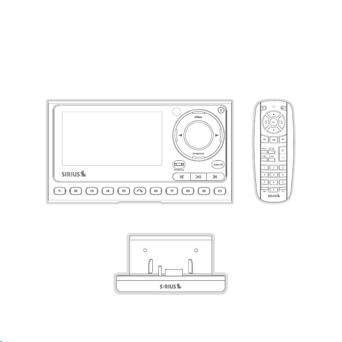
Package Contents
The following items ar e included with your SIRIUS Sportster SP5 radio:
Sport ster SP5 Radio
Vehic le Dock
Remot e Control
[ Pack age Cont ents ]
11
Page 12
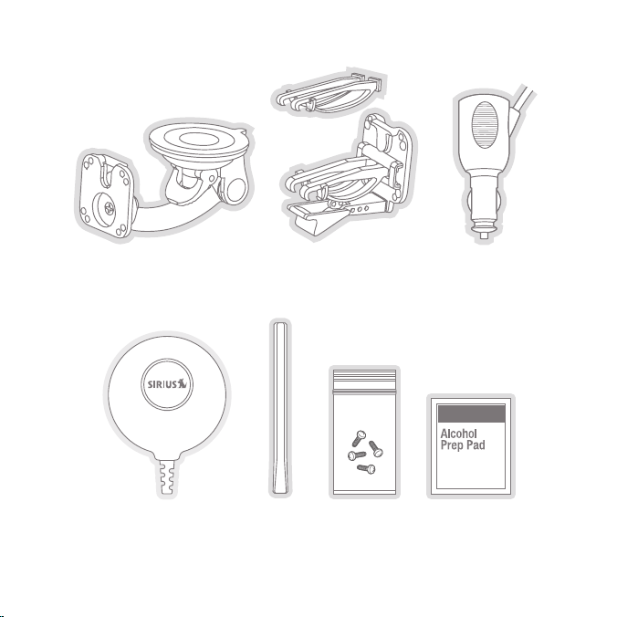
Sucti on Cup Mo unt
Vent Mount &
Exten ded Vent Hooks
Cigar ette Ligh ter
Adapt er
[ Pack age Cont ents ]
12
Magne tic
Anten na
Anten na
Cover /Tail
Mount ing
Screw s
Alcoh ol
Wipe
Page 13

Unpack your SIRIUS Sportster SP5 carefully and make sure that everything shown is
present. If anything is missing or damaged, or if your SIRIUS Sportster radio fails to
operate, notify y our dealer immediately. It is recommended that you retain the original
carton and packing mat erials in case you need to ship your radio in the future.
[ Pack age Cont ents ]
13
Page 14

Installation
SIRIUS suggests that you have your Sportster SP5 professionally-installed in
your vehicle. Prof ession al installation provides an exper ienced technician to install this product in your vehi cle, advice for selecting a suitable mou nting location for th e Vehicle Dock, installation of the antenna, and proper routing of all
the necessary wires and cables. If the locations of your SIRIUS radio and your vehicle’s FM antenna make the performance of your SIRIUS radio’s built-in FM transmitter within y our vehicle poor, a professional installer will have the necessary
accessories to install an optional FM Direct Adapter or audio cab le to connect the audio
output of the Vehicle Dock directly to your vehicle’s audio system. Ask your SIRIUS retailer if they provide professional installation services, or can recommend a professional
installation service.
Installing the Vehicle Dock
When installing the vehicle dock in your vehicle, choose a location that will not block
your vision, interfe re with the vehicle contro ls, or obstru ct the air bag. The location
should be easily accessible and provide good visibility of the displa y, and should not
be located where it will be in direct sunlight w hich will affect the visibil ity of the radio’s
display screen.
The mounting accesso ries necessary to install the vehicle dock in a vehicle are provided.
Figure 1 shows two examples of the SIRIUS radio mounted in a vehicle: A is the suction
cup mount method, and B is the vent mount method using the vent mount clip.
Note : The s upplied suction cup mount a nd vent mount should work in most vehicle s.
If your ins tallat ion req uires a diffe rent m ounting optio n, check with a loca l elec tronics retailer for other compati ble mo unts that are available se parate ly.
[ Inst alla tion ]
14
Page 15
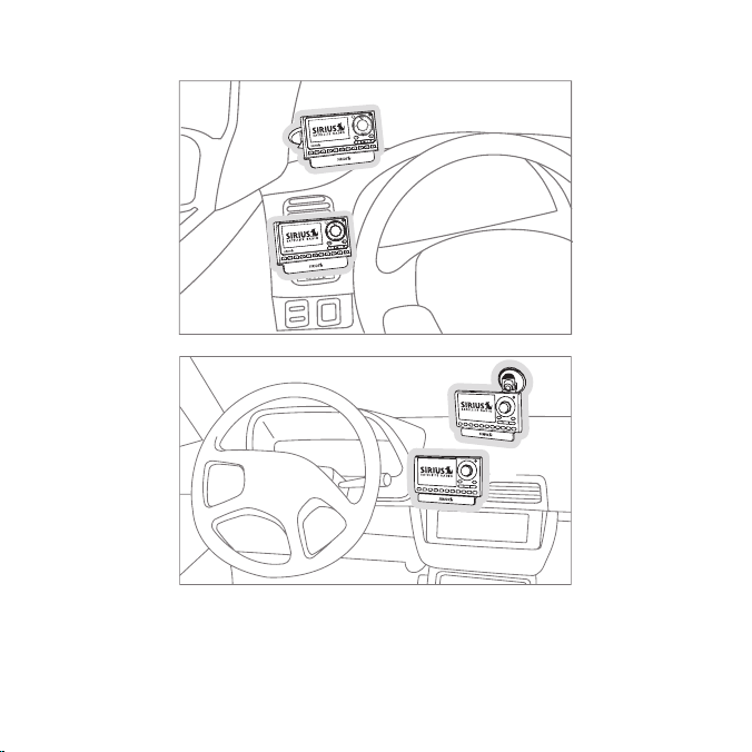
A.
B.
A.
B.
Figur e 1
Depending upon the mounting location you select in your vehicle, the mount shoul d be
attached to the vehicl e dock and installed as described in the following sections.
[ Inst alla tion ]
15
Page 16
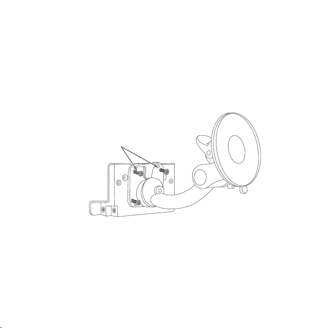
Suct ion Cup Mount Method (A)
Attach Dock
to Mount with
Included Screws
The suction cup mount may be attached to your vehicle’s windshield. Before attaching the
suction cup mount to your windshield, you should check your state and local laws for regulations
regarding mounting thi s device on your windshield.
To mount the vehicle dock using the su ction cup moun t, assemble t he mount as
follows:
Attach the vehicle doc k to the suction cup mount using the provided screws.
1.
(See Figure 2.)
Figur e 2
Clean the area where you are attaching the suction cu p with the supplied alcohol
2.
wipe.
[ Inst alla tion ]
16
Page 17
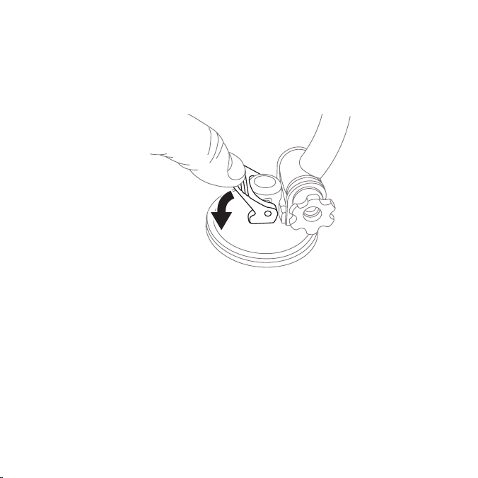
Be sure the cam lever is up (as shown in Figure 3) and position the suction cup mount
Press Lever
Down To
Lock Mount
3.
on the windshield or other location yo u have chosen. Press the cam lever a ll the way
down towards the base of the mount until it locks to firmly adhere the suction cup.
(To unlock the suction cup, lift the lever up.)
Figur e 3
[ Inst alla tion ]
17
Page 18
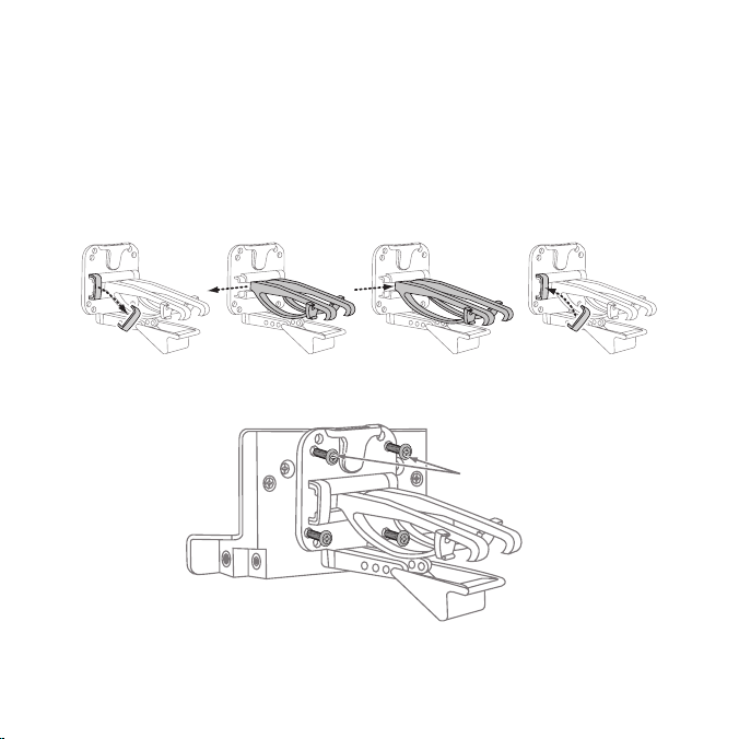
Slide Short
Vent Hooks Out
Remove
End Cap
Slide Extended
Vent Hooks In
Replace
End Cap
Attach Dock
to Mount with
Included Screws
Vent Mount Method (B)
To mount the vehicle dock using the vent mount method, install the vent mount as follows:
If the vent louvers in your vehicle are reces sed, you may need to use the longer vent
1.
hooks with the vent mount. Refer to Figure 4 and in stall the longer vent hooks into
the vent mount. Be sur e to observe the orientation of the vent hooks as shown.
Attach the vent mount to the ve hicle dock us ing the provided screws. (See Figure 5.)
2.
Figur e 4
Figur e 5
18
[ Inst alla tion ]
Page 19
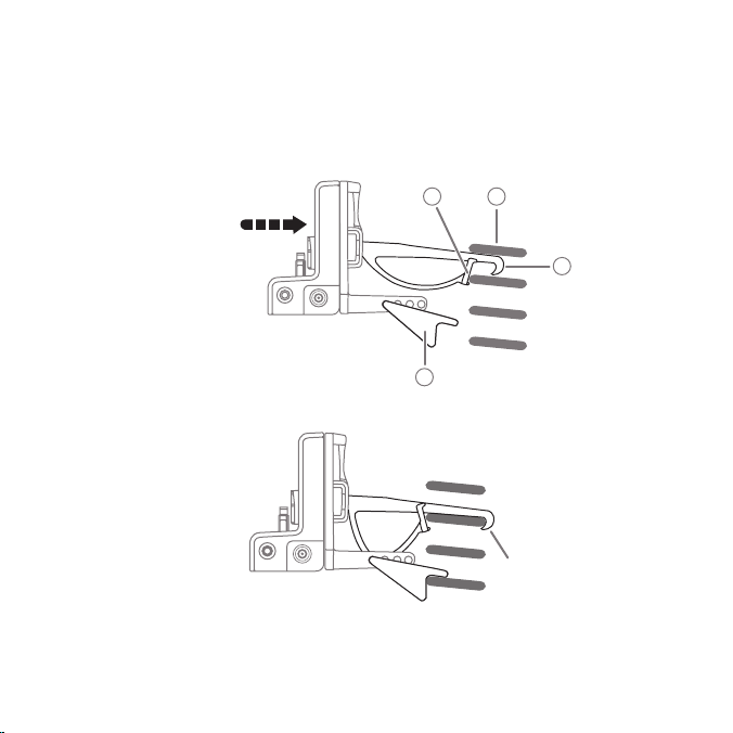
Refer to Figure 6 and attach the vent mount to a heating/air conditioning vent in
FM OUT
ANT
C
B
A
D
PUSH
FM OUT
ANT
HOOKED
3.
your vehicle. Position the two tension springs A against a vent louver B. Then push
the vent mount into the vent, far enough so that the ho oks C drop down and hook
the rear of the vent louver (see Figure 7). Once the hooks have grasped a vent
louver, the tension sp rings A will keep the vent mount hooked to the louver.
Figur e 6
[ Inst alla tion ]
19
Figur e 7
Page 20
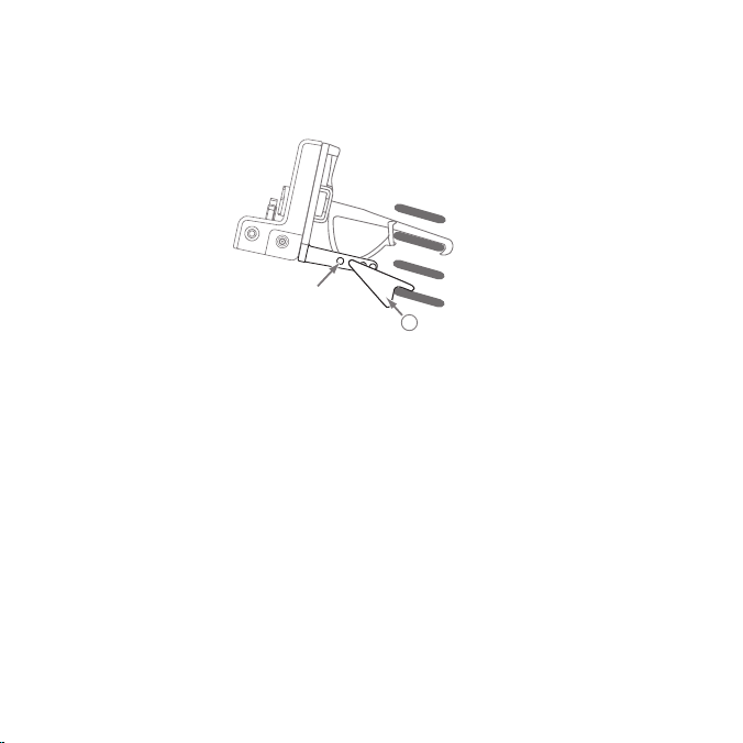
The angle of the vehicle dock ma y be changed by changing the position of foot D
FM
O
U
T
A
N
T
ADJUSTMENT
HOLES
D
4.
on the vent mount to a different adjustment hole. (See Figure 8.)
Figur e 8
[ Inst alla tion ]
20
Page 21

Installing the Magnetic Antenna
Caution
Because adhes ive is used in the installati on of the Rubber Antenna Cover/Tail, we
recommend that you install the antenna at or above room temperature (68° F). The
adhesive on the Rubber Cover/Tail may not adhere properly to the vehicle roof at temperatures lower than this. Warmer temper atures will also make it easier to route of the
antenna cab le through the rubber molding around the windows and in other areas in the
vehicle. Maximum adhesion usually occurs within 72 hours at room temperature, so you
should avoid car washes as well as other cont act w ith the antenna and Rubber Cover/
Tail during this 72 ho ur period.
Warning
Be sure not to cut, da mage, or puncture the external jacket of the antenna cable during
the install ation procedure. Damage to the ant enna cable can degrade the S IRIUS signal
or make it unav ailabl e, and can also cause water to intrude via the cable into the antenna
causing the antenna to fail.
Do not lengthen or shorte n the antenna cable by cutting it. Doing so will cause the
antenna to not functio n properly.
Installation
Installing the magneti c antenna consists of two steps:
Mounting the magnetic antenna and Rubber Antenna Cover/Tail on the vehicle
•
Routing the antenna ca ble through the vehicle to the Vehicle Dock
•
[ Inst alla tion ]
21
Page 22

Ant ennA Mou ntin g
Sedan/Coupe Pickup Truck SUV/Mini-Van
Convertible
The SIRIUS Magnetic Mount Vehicle Antenna has a strong magnetic mount designed
to hold it in place during norm al driving conditions (highway/city). This als o makes the
antenna easy to remove for transferring it to other vehicles.
Figure 9 shows the optimal mounting location for the antenna on several types of
vehicles. These mounti ng positions should be observed when installing the antenna:
Figur e 9
Seda n/Coup e/SUV/ Mini-V an: Install the antenna at the rear center of the roof,
•
near the rear window.
Pickup Truck: Install the antenna at the front center of the roof, near the windshield.
•
Conv ertibl e: Install the antenna at the front center of the trunk lid, near the rear
•
window.
[ Inst alla tion ]
22
Page 23

The SIRIUS antenna needs to have an unobstructed area of 3 inches by 3 inches
Rubber Antenna
Cover/Tail
Protective
Strips
Strain
Relief
Cable
Magnetic Antenna
(Upside-Down)
arou nd it. It is important to mount the antenn a where no obstructions will block the
antenna from receiving the SIRIUS signal. Objects which can obstruct the antenna
could be a roof rack, a sunroof, a roof-mounted cargo container, another antenna, etc.
If your v ehicle has a pot ential obstruction, be sure that the S IRIUS antenna is mounted
at least 3 inches away from it (but no closer than 3 inches from t he roof edge, or trun k
lid in the case of a c onvertible).
Note : Read the DO and DO N OT installation tips beginning on p age 32 for additional
antenna installation i nformation.
Follow this procedure to mount the antenna:
Select an appropriate mounting position for your type of vehicle that has an
1.
unobstructed area of 3 inches by 3 inches around the antenna.
Attach the Rubber Cover/Tail to the antenna, as shown in Figure 10, and press
2.
the antenna cable into the rubber cover/tail. The Rubber Cover/Tail will help to
position the antenna t he correct distance from the edge of the roof or trunk lid.
Clean the surface area of the vehicle where you will be installing the ant enna with
3.
the alcohol prep pad.
Figur e 10
[ Inst alla tion ]
23
Page 24

Peel the protective material from the adhesive strips (see Figure 10, on page 23)
4.
and press the rubber C over/Tail firmly into place on the vehicle.
Double check that the location of the antenna and rubber cover/ tail are correct, and
5.
continue to press firmly down on the Rubber Cover/Tail for another 30 seconds.
At room temperature (68° F), maximum adhesion usually occurs within 72 hours.
During this p eriod, avoid car washes and other contact with the antenna and the
Rubber Antenna Cover/T ail.
CAb le R outi ng
After you have mounted the antenna you can route the antenna cable to the SIRIUS
Vehicle Dock. Separate a ntenna cable routin g procedures are provided for each type of
vehicle: Sedan/Coupe, Pickup Truck, SUV/Mini-Van and Convertible.
Note that additional breakout illustrations for each step of the antenna cable routing
procedures can be found on the SIRIUS website at http://siriuscanada.ca. Click on the
Inst all/Ac tivate link and then follow the link for the Car Installation Tips.
[ Inst alla tion ]
24
Page 25
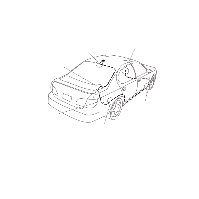
Seda n/Coupe Anten na Cable Rout ing Pr ocedure
1. F eed Cable Under
Rubbe r Molding
Around Wi ndow
4. Ro ute Cable from Tru nk Under
I nterior T rim, into Cabin an d
T owards Fr ont of Ve hicle
6. B ring Cabl e Out To
SIRIUS
Recei ver
Locat ion
5. Br ing Cable out from
T rim and R oute Unde r
C arpet to Dashboard
o r Console .
2. Ro ute Cable Out of
W indow Mol ding and
I nto Weath erstrippi ng
A round Tru nk Openin g
3. Ro ute Cable
A long Trun k Wall
a nd Into C abin
ANTENNA
Figure 11 shows how the antenna cable should be routed from the antenna to your
SIRIUS radio in a seda n/coupe.
Follow these detailed cable installation instructions:
Feed the cable f rom the antenna underneath the rubber molding around the re ar
1.
window. Use a plastic putty knife or similar object to lift the rubber molding around
the rear window and tuck the antenna cable underneat h the mol ding. Route the antenna cable arou nd and down the window to the lowest point. If your r ear window
does not have rubber molding, SIRIUS recom mends consulting with a professional
installer.
Figur e 11
[ Inst alla tion ]
25
Page 26

Route the antenna cable out of the window molding a nd into the rubber weather
2.
stripping around the trunk opening. Lift the weather stripping from the opening and
tuck the cable inside it, then replace the weather strippi ng. To avoid sha rp bends
in the cable, run the cable inside of the weather stripping for a few inches, then
remove the cable from the weather s trippi ng inside of the trunk. Keep the cable
away from hinges, gear s, etc., that could damage it.
Route the cable out from the rubber weather stripping and along the trunk wall.
3.
Continue routing the cable into the cabin through a conduit or along an existing
wiring harness.
Route the ca ble through the main cabin area unde r the interior trim, towards the fro nt of
4.
the vehicle. Use the plastic putty knife to lift the plastic tri m ju st e nough to tuck the cable under undern eath. Avoid side airbag locations on back pillars and abo ve the doors.
(Airbag locations are marked with “SRS” l ogos.) B e careful not to crimp or cut
the cable.
Bring t he cable out from the trim near the firewall a nd route it under the carpet
5.
toward the dashboard or console. Coil an y exces s cable in a hid den loc ation, such
as under the carpet, keeping it away from any vehi cle pedals or controls. Secure
the excess cable with wire ties.
Bring the end of the cable out at the SIRIUS Vehicle Dock location. Leave yourself
6.
enough cable so you can easi ly connect it to the antenna connector on the Vehicle
Dock.
[ Inst alla tion ]
26
Page 27
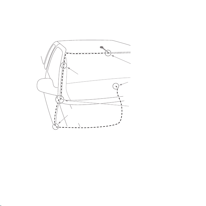
Pick up Truck Ante nna Cable Rou ting P rocedure
1. Rou te Cable Un der
Ru bber Moldin g
Ar ound Windsh ield
2. Con tinue Tucki ng Cable
Un der Molding To
Bo ttom of Win dshield
3. Rou te Cable Ou t of Moldi ng
an d Into Weat herstrippi ng
Ar ound Door O pening.
Co ntinue to B ottom of
Do or Opening.
4. Bri ng Cable ou t from
We atherstripp ing and
Ro ute Under C arpet
5. Bri ng Cable Ou t to
SI RIUS Receiv er
Lo cation
ANTENNA
Figure 12 shows how the antenna cable should be routed from the antenna to your
SIRIUS radio in a pick up truck.
Figur e 12
Follow these detailed cable installation instructions:
Use a plastic putty knife or si milar tool to lift the rubber molding around the wind-
1.
shield and tuck the an tenna cable underneath it.
Continue tucking the cable underneath the windshield molding aro und the wind-
2.
shield to the lowest c orner.
[ Inst alla tion ]
27
Page 28

At the lowest corner of the windshield, route the cable out of the windshield mold-
3.
ing an d into the rubber weather stripping around the door openin g. Lift the weather
stripping from the opening and tuck the cabl e inside it, then replace the weather
stripping. Run the cable inside of the weather stripping to the bottom of the door
opening.
Pull the cable out of the weather stripping at the bottom of the door opening and
4.
route it under the carpet toward the dashboard. Coil any excess cable in a hidden
location, such as under the carpet, keeping it away from any vehicle pedals or
controls. Secure the e xcess cable with wire ties.
Bring the end of the cable out at the SIRIUS Vehicle Dock location. Leave yourself
5.
enough cable so you can easi ly connect it to the antenna connector on the Vehicle
Dock.
SUV/ Mini-Van Ante nna Cable Rou ting P rocedure
Figure 13 (on page 29) shows how the antenna cable should be routed from the
antenna to your SIRIUS radio in an SUV or a Mini-Van.
[ Inst alla tion ]
28
Page 29
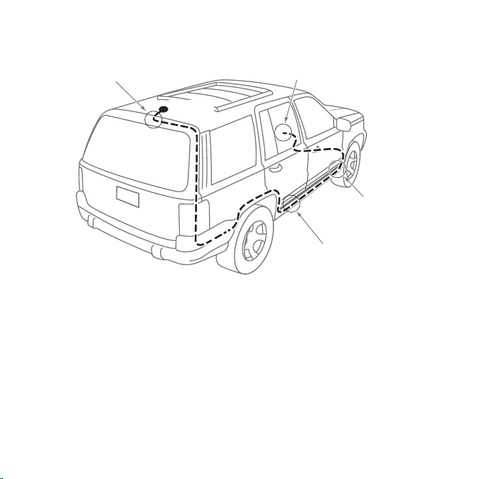
1. F eed Cable Under
Rubbe r Seal Around
Hatch Opening
3. Ro ute Cable
Under Carpet
to Da shboard
4. B ring Cable Out To
SIRIUS
Recei ver
Locat ion
2. Ro ute Cable Under I nterior
T rim, into Cabin a nd
T owards Front of V ehicle
ANTENNA
Follow these detailed cable installation instructions:
Feed the antenna cable underneath t he rubber weather stripping of the rear tail-
1.
gate window/door and route t he cab le alo ng the rear hatch. Lift the weather stripping from the opening and tuck the cable inside it, then replace the weather strip ping. Pull the cable out from weather stripping and route it into the cabin under the
interior trim. Avoid h inges or gears that could crimp or cut the cable.
Route the cable through the SUV’s main cabin area under the interior trim, towards
2.
the front of the vehicle. Use a plastic putty knife to lift the plastic trim just enough
to tuck the cab le under undern eath. Avoid sid e airbag locations on back pillars and
above the doo rs. (Airbag locations are marked with “SRS” logos.) Be careful not
to crimp or cut the ca ble.
Figur e 13
[ Inst alla tion ]
29
Page 30
Bring t he cable out from the trim near the firewall a nd route it under the carpet
6. Br ing Cable O ut To
S IRIUS
Receiv er
Locati on
1. Bri ng Cable fr om
An tenna Into Inside
of Trunk Lid
2. Tap e Cable Alo ng
In side of Lid to
Hi nge Strut
4. Rou te Cable fr om Trunk
Un der Interio r Trim, int o
Ca bin and Tow ards Front
of Vehicle
5. Bri ng Cable ou t from
Tr im and Rout e Under
Ca rpet to Das hboard
or Console.
3. Tie Cable to H inge Strut, Allowing
Sl ack for Lid to Open an d Close.
Ro ute Cable I nto Cabin
Th rough Exist ing Wire
Ch annel.
ANTENNA
3.
toward the dashboard or console. Coil an y exces s cable in a hid den loc ation, such
as under the carpet, keeping it away from any vehi cle pedals or controls. Secure
the excess cable with wire ties.
Bring the end of the cable out at the SIRIUS Vehicle Dock location. Leave yourself
4.
enough cable so you can easi ly connect it to the antenna connector on the Vehicle
Dock.
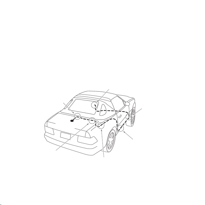
Conv ertible Anten na Cable Rout ing Pr ocedure
Figure 14 shows how the antenna cable should be routed from the antenna to your
SIRIUS radio in a conv ertible.
30
[ Inst alla tion ]
Figur e 14
Page 31

Follow these detailed cable installation instructions:
Bring the cable from the antenn a into the trunk at the front edge of the trunk lid.
1.
Keep any ben ds in the cable loose. Tape o r tie the cable along the inside of the
trunk lid to the trunk lid hinge strut.
Allow enough slack in the cable so the trunk lid can easily open and close and
2.
keep the cable a way from hinges, gears, etc., that could crimp or cut it. Route the
cable along the trunk wall and into the cabin through a conduit or along an exist ing
wiring harness.
Route the ca ble through the main cabin area under the interior trim, towards the
3.
front of the vehic le. Use a plastic putty knife to lift the plastic trim just e nough to
tuck the cable under underneath. Avoid sid e airbag locations on back pillars and
above the doo rs. (Airbag locations are marked with “SRS” logos.) Be careful not
to crimp or cut the ca ble.
Bring t he cable out from the trim near the firewall a nd route it under the carpet
4.
toward the dashboard or console. Coil an y exces s cable in a hid den loc ation, such
as under the carpet, keeping it away from any vehi cle pedals or controls. Secure
the excess cable with wire ties.
Bring the end of the cable out at the SIRIUS Vehicle Dock location. Leave yourself
5.
enough cable so you can easi ly connect it to the antenna connector on the Vehicle
Dock.
[ Inst alla tion ]
31
Page 32

tip s
The following DO and DO NOT antenna mounting tips illustrate how to install the
antenna for optimal performance, and a lso illustrate where the antenna s hould not be
installed.
Mount the antenna
DO
DO
32
on the roof, at least
3 inches from the
edge.
Mount the antenna on
the roof where it has
a clear view of the
sky in all directions.
[ Inst alla tion ]
Page 33

DO
3”
DO
Mount the antenna
on the roof where it
has at least 3 inch es of cl ear space
around it.
Use the supplied
Rubber Tail Cover to
protect the ant enna
cable.
[ Inst alla tion ]
33
Page 34

DO
NOT
Don’t mount the
antenna inside the
vehicle, for example,
on the dashboard.
DO
NOT
34
Don’t mount the
antenna on any of th e
vehicle’s front, back
or side pillars.
[ Inst alla tion ]
Page 35

DO
NOT
DO
NOT
Don’t mount the
antenna close to a
roof rack. Adjust the
rack so it’s further
away from the antenna or move the
antenna closer to the
center of the roof.
Don’t mount the
antenna close to
another antenna.
Mount it at least 3
inches away.
[ Inst alla tion ]
35
Page 36

Don’t mount the an-
FM OUT
ANT
Vehicle Dock
(Right Side)
Antenna
Connection
Antenna
Cable
Connector
tenna closer than 3
inches from the edge
DO
NOT
of the roof. Us e the
supplied rubber t ail/
cover as a guide for
judging prop er length
and correct positioning.
After you’ve routed the c able to the SI RIUS Vehicle Dock, c onnect the antenna c able to
the Ant connection on the right side of the Vehicle Dock. (See Figure 15.)
Figur e 15
36
[ Inst alla tion ]
Page 37

Connecting the Cigarette Lighter Adapter
Mounting
Slots
AUDIO
5VDC
Vehicle
Dock
(Left Side)
5V DC
Connection
12V
Power
Outlet
Cigarette Lighter
Adapter
Connect the provided cigarette lighter adapter to the 5VDC connector on the back of the
Vehicle Dock. (See Figure 16.)
Note : Do not p ower the Vehicle Dock directly f rom your vehicl e’s 12VD C power
syst em wi thout using the Cigaret te Lighter Adapter . Thi s could d amage the Ve hicle
Dock , your SIRIUS radio or bot h.
Docking Your SIRIUS Radio
To place your SIRIUS SP5 into
the Ve hicle Dock, align the radio against the rea r of the Dock
so that the rails on the Dock fit
into the mounting slots in the
back of the radio (Figure 17).
Slide the radio all the way down
onto the Dock so that it fits firmly.
Figur e 16
Figur e 17
[ Inst alla tion ]
37
Page 38

Connecting Your SIRIUS Radio to Your Vehicle’s Audio
AUDIO
5VDC
Stereo Cable (Sold Separately)
AUDIO
Jack
Vehicle Radio
To AUX IN
or LINE IN
Connector
Vehicle Dock
(Left Side)
System
There are two ways to connect your SIRIU S Sportster SP5 to your vehicle’s audio system:
Direct Connection or Wireless Connection. Which one w ill perform best in your vehicle
depends on your vehicl e’s audio system.
For the latest informa tion go to http://www.siriuscanada.ca/en/install/vehicle.aspx.
Direct Wired Audio Connection
If your veh icle’s audio system has an “Aux in” or “Line in” jack it is the best-quality audio
connection you can use for your SIRIUS radio. (And if th e Aux in or Line in connector is
located somewhere on the front of your veh icle radio or elsewhere in the cabin, this is
also the easiest way t o connect your SIRIUS radio.)
1. Purchase an audio cable that matches the connection type of your vehicle’s audio
system and your SIRIUS Vehicle Dock at your local electronics retailer.
• The Vehicle Dock requires a male
2. Plug the cable’s mal e
Vehicle Dock. Plug the other end into the Aux in/Line in connector on your vehi cle’s
1
” stereo connector into the AuD io jack on the left si de of the
/
8
audio system. (See Figure 18.)
[ Inst alla tion ]
38
1
” stereo connector.
/
8
Figur e 18
Page 39

Direct FM Audio Connection
FM OUT
ANT
Vehicle Radio
Antenna
Connection
Vehicle
Antenna
FM OUT
Jack
Vehicle Dock
(Right Side)
FM Direct Adapter
(Sold Separately)
If your vehicle’s audio system does not have an Aux In/Line In connection, a SIRIUS FM Di rect Ad apter (sold separately) will provide the next best quality connection between your SIRIUS radio and your vehicle radio. You will listen to your
SIRIUS radio throu gh your car radio’s FM tuner, but the SIRIUS FM Direct Adapt er
connects your vehicle’s FM radio directly to your SIRIUS radio’s FM Out j ack,
eliminating the outside static and interference you sometimes experience when
using a wireless FM co nnection. (See Figure 19.)
Figur e 19
NOTE : Profess ional in stallation may be required. See your local SIRI US retai ler.
The SIRIUS FM Direct Ad apter is available at you r loc al SIRIUS retai ler o r at
http://shop.siriuscanada.ca. Follow to the instructions included with the FM Direc t
Adapter.
[ Inst alla tion ]
39
Page 40

Cassette Adapter
AUDIO
5VDC
Vehicle Radio
Cassette Adapter (Sold Separately)
Vehicle Dock
(Left Side)
AUDIO
Jack
If your vehicle’s au dio system has a cassette player you can purchase a cassette adapter from
your local electronics retailer or from SIRIUS at http:// shop.s irius.com. Plug the adapter’s
connector into the AuDio jack on the left side of the Vehicle Dock , and insert the adapter
into your vehicle’s ca ssette player. (See Figure 20.)
Figur e 20
Note : Refer to th e cassette ad apter’ s instruction s for correct use.
Wireless Connection
If you cannot connect your SIRIUS radio directly to your vehicle’s audio system, your
SIRIUS radio contains an FM tran smitte r that will ‘broadcast’ its audio to your vehicle’s
FM radio.
To use this you need to tune the SIRIUS receiver’s FM transmitter to an FM frequency
that’s not being used in your area (If you use an FM channel that is being used by a
local broadcaster, it will interfere with the performance of your SIRIUS radio.)
See Figure 21, opposite..
[ Inst alla tion ]
40
Page 41

Vehicle
FM Antenna
SIRIUS Sportster SP5Vehicle Radio
Match Frequencies
Figur e 21
FM Presets
Button
Knob
1. Tune through your vehicle radio’s FM channels to find an FM channel (between 88.1MHz
and 107.9MHz) that is not broadcasting in your area.
2. Once you have located an FM channel that is not broa dcasting in your area, save it as
a preset on your vehic le radio. This will become your SIRIUS preset.
3. Dock your SIRIUS receiver and tu rn its power ON. Wait for the Channe l Update to
finish before pressing any buttons.
4. Press and hold the FM Presets button (see Figure 22, left). The Men u optio ns screen
will appear. Rotate th e Knob to highlight set tings a nd pre ss the Knob to select it.
5. The setti ngs screen will appear (see Figure 22, right). Rotate the Knob to highlight
FM trAnsMi tter and press the Knob to select it.
Figur e 22
[ Inst alla tion ]
41
Page 42

6. The FM tr AnsMitt er screen will appear (see Figure 23, left). Rotate the knob to hig hlight set FM pre sets and press the Knob to select it .
Figur e 23
7. The set FM pre sets screen will appear (see Figure 23, right). FM1 will be highlighted.
(FM1 is factory-set to 88.1MHz. This may not be the best frequency for your area.)
8. Press the Knob to select FM1. The set FM pr eset 1 screen will appear (see
Figure 24, left).
Figur e 24
9. Rotate the Knob to highlig ht the FM frequency that match es the channel that you
preset on your vehicle radio in Step 2 on page 41, then press the Knob to select it.
(See Figure 24, right. )
To listen to your SIRIUS radio, turn your SIRIUS radio ON, then turn your vehicle’s FM
radio ON and press the SIRIUS preset you set in Step 2 on page 41.
TIP: If you regularly travel between cities with different active FM channe ls, you may
need to find channels that are not broadcasting in each city. Your SIRIUS Sport ster SP5
[ Inst alla tion ]
42
Page 43

can store up to 5 preset FM transmit channels (see Figure 23, right), so you can easily
“FM OUT” JACK
2.5 MM PLUg
switch to the best FM channel for each city.
• To switch the FM transmit preset, press the FM Pr esets button on eith er the SP5 front
panel or the remote.
If you’re not sure which FM channels are not broadcasting in your home or travel cities, you can also go to http: //www. siriuscanada.ca/en/install/frequency.aspx and
search for a suggested FM channel based on your zip code.
Inst alling the FM Transmitter Antenn a
Note: You will only need to install the FM Transmitter Antenna (FMTA) if you are using the wireless
connection option. The use of the FMTA is highly recommended to improve your audio quality.
The FMTA brings the FM signal transmitted by your SIRIUS radio closer to your vehicle’s
FM antenna to provide a strong FM signal for good reception. To install the FTMA:
Connect the FMTA to the vehicle dock. Ins ert the FMTA 2.5 mm plug into the FM
1.
OUT connector of the v ehicle dock. (See Figure 25, left.)
Position FMTA inside the vehicle. The FMTA wire should be run with the power
2.
adaptor wire, and placed on the dash board or even placed under the dash pad
(if possible). (See Figure 25, right.) If your Sportster is mounted to the center
console, the FTMA wire should be run along console.
Hide the wires. Depending on the position of your Sportster, hide the wires by tuck-
3.
ing them into the seams in the dash board or the console seams where possible.
Figur e 25
[ Inst alla tion ]
43
Page 44

Subscribing to the SIRIUS Service
Before you can list en to the SIRIUS service, you need to subscribe to the SIRIUS
Satellite Radio servic e. To subscribe, do the following:
Be sur e that your SIRIUS Sportster SP5 is correc tly installed, is properly dock ed in
1.
the Vehicle Dock, and that the antenna is oriented to receive the SIRIUS signal.
Turn on the SP5. After the startup sequence, it will upd ate the SIRIUS
2.
channel line-up. Wait until the channel u pdates have completed befor e pressing any
buttons.
Once the channels have been updated, the radio will automatically tune to
3.
channel 184 and the display will change to Call 1-888-539-SIRIUS to Subscribe.
You will not be able to listen to a ny other channels until you activate your SIRIUS
subscription.
Use the SP5’s Knob to tune to channel 0 to display your SP5’s unique 12-digit
4.
SIRIUS ID Number ( SID). You can also tune to channel 0 by using the remote
control: Press the seLec t b utton, then the 0 (zero) button, and then the seLect
button again. The SID number is also avai lable on your SP5’s packaging, and may
also be accessed by pressing the Menu button and selecting sir ius iD. Write t he
SID number down.
Have your credit card ha ndy and contact SIRIUS on the Internet at:
5.
http s://ac tivate .siriu scanada.ca/ and follow the prompts to activate your
subscription. You can also call SIRIUS toll-free at 1-888-539-SIRIUS (1-888-539-
7474).
When you have successfully subscribed to the SIRIUS service your SP5 will
6.
display an alert. To c ontinue, press the Knob.
You a re now ready to begin enjoying SIRIUS Satellite Radio’s digital entertainment, and
can tune to other chan nels!
[ Inst alla tion ]
44
Page 45

Controls
5
8
12
10
4
13 14 13
11
2
6
9
7
1
3
SIRIUS Sportster SP5 Front Panel
Figure 26 and the section following identify and describe the SIRIUS Sportster SP5’s
buttons and controls.
Figur e 26
[ Cont rols ]
45
Page 46

Colo r LCD Dis play Screen: Provides information about the SP5’s operation, the
1.
program that is playin g and other programming that is available.
FM Presets/Me nu But ton: Lets you select between the diffe rent FM preset
2.
frequencies used by the SP5’s built-in internal FM transmitter. Press-and-hold
accesses Menu options to make setup and feature changes.
IR R eceive r: Receives IR signals from the included remote control.
3.
Disp lay (Disp ) Button: Pressing and releasing this button changes the text size
4.
of artist names and song titles on t he display screen. Pressin g and holding this
button displays the la st screen viewed in the Channel List mode (see page 53).
Powe r Butt on: Turns th e SP5 ON and OFF.
5.
Cate gory Buttons: Press-and-release navigates through the cAtego ry List scree ns
6.
which di splay the SIRIUS channel categories. Pre ssing and holding the buttons
increase or decrease the display’s brightness, or lets you adjust the Auto Brightness
settings, depending on the option selected in the Menu Options (see page 80).
Rota ry Knob/ Select Button: Rotating the Knob naviga tes through the different
7.
display screens; pressing the Kno b makes selections of items highl ighted on the
display screen. Rotating clockwise increases the channel numbe r (down the list),
and moves down when in a menu list; rotating counterclockwise decreases the
channel number (up the list), and moves up in when in a menu list. When not in
a menu or list, pressing the Knob selects the channe l entered using the Preset
Number buttons.
Memo ry (MeMo) Butto n (S-Seek Funct ion): Pressing and releasing this button saves
8.
artist name s and song titles. You can store up to 30 artist/song title combinations,
including favorite teams and traffic channels. Pressi ng and holding the MeMo button will enter the rec all mode, displaying the stored artist/song titles.
Band Button : Pressing and releasing this button switches between the preset
9.
banks A, B, and C, which hold 10 presets each for a total of 3 0. Pressing and
holding this button switches to the My pr esets category, which lets you see what
artists and songs are playing on each of your stored presets.
[ Cont rols ]
46
Page 47

Rewi nd But ton: Used to rewind throug h cont ent sa ved to Instant Re play.
10.
Pressing a nd releasing this button rewinds to the beginning of the song or
program. Pressing and holding rewinds by time through the saved content.
Fast -Forwa rd Button: Used to fast-forward through Instant Replay sa ved
11.
content. Pressing and releasing this button fast-forwards to the beginning of the
next song or program. Pressing and holding fast-forwards by time through the
saved content.
Play /Pause Butto n: Pauses and replays live or time-shifted cont ent from the cur-
12.
rently tuned channel. Pressing and holding thi s button displays the list of Saved
content.
Numb er Buttons (0 – 9): S et and select preset channels. Also used to directly-
13.
select channels.
Jump Button: Jumps to a preset favor ite channel. Pressing the but ton again
14.
returns back to the or iginal channel.
[ Cont rols ]
47
Page 48

Remote Control Buttons
91
8
3
5
4
6
7
2
11
12
13
14
15
16
10
Figure 27 and the sect ion following identify the remote control’s buttons.
Powe r Butt on: Turns th e SP5 ON and OFF.
1.
2.
Sele ct Button: Selects item s highlighted in a list; hold-down to jump to the previously-
received channel. When not in a menu or list, pressing the Select button selects the
channel entered using the number buttons.
Figur e 27
48
[ Cont rols ]
Page 49

Cate gory Buttons: Press and release navigates through the cAtegor y List screens
3.
which di splay the SIRIUS channel categories. Pre ssing and holding the buttons
increase or decrease the display’s brightness, or lets you adjust the Auto Brightness
settings, depending on the option selected in the Menu Options (see page 80)
FM Pr esets B utton: Select s between the different FM preset frequencies used by
4.
the SP5’s built-in int ernal FM transmitter.
Menu Button: Accesses the Me nu opt ions to make setup and feature changes.
5.
BanD Button: Pressin g and releasing this button switches between the preset
6.
banks A, B, and C, which hold 10 presets each for a total of 3 0. Pressing and
holding this button switches to the My pr esets category, which lets you see what
artists and songs are playing on each of your stored presets.
Memory (MeMo) Button (S-Seek Function): Pressing and releasing this button saves
7.
artist names and song titles. You can store up to 30 artist/song title combinations.
Pressing and holding will enter the recall mode, displaying the stored artist/song titles.
Disp lay (Disp) Button: Pressing and r eleasing this butto n changes the text size of
8.
artist names and song titles on the display s creen. Pres sing and holding this button displays the last screen viewed in the Channel List mode (see page 53).
Mute Button: Mutes the SP5’s audio output.
9.
Chan nel UP /DOWN Button s: Nav igates through channels and display screens.
10.
Rewi nd Button: Used to rewind through content saved to Instant Replay. Pressing
11.
and releasing th is button rewinds to the beginning of the song or pro gram. Pressing and holding rewind s by time through the saved content.
Fast-Forward Button: Used to fast-forward through Instant Replay saved content.
12.
Pressing and releasing this button fast-forwards to the beginning of the next song or
program. Pressing and holding fast-forwards by time through the saved content.
Play/Pause Button: Pauses and replays live or time-shifted content from the cur-
13.
rently tuned channel. Pressing and holding this button displays the list of Saved
content.
VOL+ / VOL– Butto ns: In crease s or decreases the audio volume.
14.
Numb er But tons ( 0–9): Select channels directly and select preset channels.
15.
[ Cont rols ]
49
Page 50

Jump Button: Jumps to a preset favor ite channel. Pressing the but ton again
Insert Battery
“+” Side Up
Remove
Cover
16.
returns back to the or iginal channel.
Remo te Control Ba ttery Install ation
To install the re mote control battery, turn the remote control over and l ocate the battery
cover near t he bottom edge. Open the battery co mpartment and place the battery in the
compartment with the + side of the battery facing up. Replace the battery cover on the
remote control. See Figure 28.
Figur e 28
50
[ Cont rols ]
Page 51

Vehicle Dock Reference Guide
AUDIO
5VDC
FM OUT
ANT
1 2 433 5
Figure 29 and the section following identify and describe the Vehicle Dock’ s features
and connectors.
Figur e 29
DC5V Power Connector: Power connection for the supplied cig arette lighter
1.
adapter (see page 37).
Audi o Out (au Dio) Connector: Audio output for directly connecting to your vehi-
2.
cle’s audio system (se e pages 38 & 40).
Dock ing Ra ils: Fit-into slots in the back of the SP5 to secure it while it is docked
3.
(see page 37).
FM out Connector: FM output for use with the optional FM Direct Adapter (see
4.
page 39).
Antenna (ant) Connec tor: Connec tion for the supplied magnetic antenna (see
5.
page 36).
[ Cont rols ]
51
Page 52

Operation
3-Digit
Channel Number
Channel Name
Band/Preset
Bank Number
Auto-Sizing/Scrolling
Artist Name
Auto-Sizing/Scrolling
Song Title
SIRIUS Signal
Strength Meter
8-Character
Category Name
Clock
Display Screen Information
Your SIRIUS Sportster SP5’s display screen pr ovides information about the operation of
the radio, such as the currently tuned channel, song or show b eing played, artist name,
time and other information. This screen is referred to as the Default screen in this manual.
Figure 30 identifies t he information displayed when listening to a typical broadcast.
Whenever you power the SP5 ON, the previously-selected channel will automatically
begin playing, and the currently-playing artist name and song title will be displayed.
[ Oper atio n ]
52
Figur e 30
Page 53

Navigating Menus and Lists
2-Line Text Format Large Text Format
The menu and list structures in your SIRIUS S portster SP5 are navigated by turning
the Knob to scroll through a menu or list to highlight your choice, and then pr essing
the Knob to select the choice. When using the remote control, menus and lists are
navigated by p ressing the Channel UP/DOWN but tons, and then pressing the seLect
button to select the c hoice.
Display (Disp) Button
Pressing and releasing the Disp button while the Default screen is d isplay ed toggles
between the 2-line artist name/song title text and large character displayed text (see
Figure 31). The large character format will change the character size and cause the field
to scroll fr om right to left. This fe ature is useful when viewing the display s creen from
a distance. Note t hat the displayed text will scroll only if the length of the artist or title
cannot be viewed in it s entirety.
Figur e 31
[ Oper atio n ]
53
Page 54

Pressing and holding the Disp button for 1½ seconds enters the Channe l List mode.
Channel NameCombination List
Song Title Artist Name
Once the Channel List mode is ac tive, r epeate dly pressing and releasing the Disp button
will cycle the display between these four screens (see Figure 32):
• Combina tion List S creen: Displays a list of chann el numbers and names along with the
currently-playing song titles and artist names on each channel.
• Ch annel Name S creen: Displays a list of channel numbers and channel names.
• Ar tist N ame Sc reen: Displays a list of the currently-playing artists on each channel.
• So ng Tit le Scr een: D isplays a list of the currently-playing songs on each channel.
Figur e 32
To exit the Channel List mode and return to the Default screen, press and hold the Disp
button.
[ Oper atio n ]
54
Page 55

Search Modes (Preset, Category, Channel, Artist, Song Title)
You can search for a nd select music four ways o n your Sportster SP5: by category, by
channel, by artist, an d by song title.
Sear ching Categor ies
If you want to browse different entertainment categories, press either Categor y button to
activate the Category Search mode, which will display a list of the currently-playing
artists and currently-playing song ti tles on the different channels o f the currently-active
category.
Use the Category buttons to scro ll through
1.
the music and entertainment categories
(see Figure 33). Note th at your preset ch annels
will be displayed as t he My prese ts category.
When the category you want is displayed
2.
(for example, Pop), use the Knob to browse
the available channels within the category
(on the remote, use the Channel UP/DOWN
buttons). When the desired channel is highlighted, press the Se lect button t o select
it. The channel will be selected and the
display w ill revert to the Default screen for the
selected channel.
Figur e 33
[ Oper atio n ]
55
Page 56

Pressing the Dis p button while in the cat-
Channel Name
Artist Name
Song Title
3.
egory search mode wi ll cycle between the
category’s channel names, the cur rentlyplaying artist names, and the currentlyplaying song titles to enable you to preview
what is playing on othe r channels before
making a selec tion. (See Figure 34.) When
the channel/artist/song you w ant is highlighted, press the Select button. The channel will
be selected and the display will revert to the
Default screen for the selected channel.
To exit the Category mode without changing
4.
to a ne w channel, press and hold the Disp
button for one second.
[ Oper atio n ]
56
Figur e 34
Page 57

Sear ching Channel s (Channel Li st Mod e)
Channel Name
Song Title
Artist Name
It is possible to search fo r a different channel while listening to your current channel. Be
sure that the display shows the Default display screen prior to the following steps:
Press and h old the Disp button for two
1.
seconds to activate the c hannel list mode.
The channel li st screen be displayed,
showing all a vailable chan nels regardless of category. Pressin g th e Disp button
while in the channel list mode will change
between channel name, artist nam e, and
song title (see Figure 35). You can use this
feature to search for a specific artist, song,
or show that may be pl aying at the time.
Turn the Knob to locate the channel you
2.
want (on the remote, use the Channel UP/
DOWN buttons).
Press the Select button to select the
3.
channel. To exit the channel list mode
without changing t o a new channel, press
and hold the Dis p button for one second.
Note : If you are in the channe l l ist mode and
view ing a sports catego ry channel list (NFL®
Zone , NHL® Zone, NBA® Zone) , pressing the
Disp button w ill toggle betw een the team
name s an d t he c urrent sco re of a ny live playby-p lay game.
Figur e 35
[ Oper atio n ]
57
Page 58

Direct Tuning
Channels can be directly accessed by pressing and releasi ng the Knob and then using the
0 – 9 keys to enter the desir ed channel number ( see Figure 36). Once the desired
number has been enter ed, the channel will change a nd the display will revert to the
Default screen for the selected channel. The SP5 will tune the channel immediately if
three numbers are entered (for example, “0 ”, ”0”, “7”), but if just one or two di gits are
entered, the radio wil l tune to the new channel after three seconds.
Figur e 36
Channel Presets
Channel presets lets yo u store up to 30 of your favorite channels as presets for quick
access with the press of a button.
Sett ing Channel P resets
Presets are stored in three banks, A, B, and C, each containing 10 channel presets.
Press the BAnD button to activate the pres et bank you want. The selected bank is
1.
shown in the lower right corner of th e Default display screen (s ee Figure 30, on
page 52).
Select the channel you want to preset.
2.
Press and hold for two seconds the numbered preset button (0 – 9) in which you
3.
want to store the chan nel.
[ Oper atio n ]
58
Page 59

The selected preset numbe r wi ll flash and then remain lit on the display to show
4.
that it has been memor ized.
If the preset button you selected al ready has a channel stored in it, the preset will be
replaced with the newl y stored channel.
Reca lling Channel Presets
The 10 preset s in the active bank (A, B, or C) can be sele cted by pressing the 0 through
9 buttons.
Press the BAnD button to activate the pres et bank you want. The selected bank is
1.
shown in the lower rig ht corner of the default display screen.
Press the desired preset button 0 – 9 to select the preset. The channel wil l change
2.
and the display will revert to the Default screen for the new chann el, with the preset shown in the lower right corner.
Pressing and holding t he BA nD button displays the My prese ts screen (see below).
My P resets screen
You can use the Knob t o quickly see what’s playing on all of your presets:
Press and hold the BAnD button to activate the My presets screen (see Figure 37).
1.
Figur e 37
Turn the Knob in either direction to move through the presets. When the preset you
2.
want to listen-to is h ighlighted, press the Select button to tune to it.
[ Oper atio n ]
59
Page 60

Turning the Knob will cycle through all of the stored preset s by preset bank and number
(for example, A-1, A-2...B- 1, B-2...C-1,C-2...). Continu ing to turn the Knob after the last
stored preset is displ ayed will return back to the first stored preset.
To exit the My pre sets screen and return to Default display screen, press and hold the
BAnD button.
Jump Button
Your SIRIU S Sportster SP5 features a special button
called Jump. This button can be programmed to jump
to a channel which is accessed frequently and temporarily such as weather, news, o r sports. The JuMp button lets you quickly tune to a specific cha nnel and then
tune back to the original c hannel by pressing the button
again (see Figure 38).
Refer t o Jump sett ings on page 79 fo r information on
configuring the JuMp b utton.
If the Ju Mp button is set to JumpSet, pressing the JuMp button will immediately tune to t he
programmed channel. Pressing the JuMp button again
will return to the channel to which you had been l istening immediately prior to pressing the JuMp button.
Note : The JuMP button settin g remains the same re-
gard less of which preset bank is cur rently select ed.
Figur e 38
[ Oper atio n ]
60
Page 61

Memory (MEMO) and Song Seek (S-Seek) Functions
Your Sportster SP5 lets you to capt ure and store information (artist, song, sports team,
or traffic city) about the programming on the curre ntly-t uned channel, up to a total of 50
items. The SP5 then co ntinuously searches all the SIRIUS channels and alerts you when
a match to a saved pro gram is being played. When a sports team (or teams) are stored
in memory, at the time the radio is initially powere d on, you will be alerted when the
sports teams are playing in a ga me being broadcast. Also, while listen ing to your SIRIUS
radio, you will be ale rted should one of the teams begin to play a game.
[ Oper atio n ]
61
Page 62

Stor ing Artist Na mes, Song Tit les, a nd Sports Tea ms to Memory
If you are listening to a song or other entertain ment channel, or a sports team, and wish
to save the artist, song, or sports team select ion to memory for future S-Seek alerts, do
the following:
For Artist Names o r Song Titles : If the currently tuned-channel is a music or entertainment channel, momentarily press and release the MeM o button. The rad io will
display a menu to choo se to store the artist name or the song title (see Figure 39).
Figur e 39
If eithe r the artist name or song title is not available to save, the choice will be
displayed as unavailab le (see Figure 40).
Figur e 40
Turn th e Knob (on the remote, use the Channel UP/DOW N buttons) to h ighlig ht store
Arti st or store son g (when available) and press the Select button to save the
current selection to m emory.
[ Oper atio n ]
62
Page 63

If both the artist and song are avai lable to save, you will be prompted again to save
Figur e 41
Figur e 42
whichever one you hav en’t yet saved, song title o r artist name. If you do not wish to
save, press the MeMo b utton to exit.
For Sports Events: If the currently-tuned channel is an NFL, NBA, NHL, NASCAR
or college play-b y-play sports broadcast, momentarily press and releas e the MeMo
button. The SP5 will display a menu to choose which sports team (or for NASCAR,
which car number) shou ld be saved to memory (see Figure 41)
If either of the teams is not available to save , that team will be displayed as unavailable (see Figure 42).
Turn the Knob (on the remote, use the Channel UP/DOWN buttons) to highlight the
desired sports team or car number (when available) and press the Select butt on to
save the current selec tion to memory.
[ Oper atio n ]
63
Page 64

The next screen will a sk which kind of alert you wish to have (see Figure 43).
Figur e 43
aler t: in itial will provide a pop-up alert when the team you have chosen is playing
a game; All will provide a pop-up alert when the team you have chosen is playing a
game, and when the sco re for the game is updated.
tick er: Displays the information (including the channel that is carrying the game) for
the team continually d uring a game they are playing. The currently-playing artist and
song title will still be visible when the ticker is active.
Turn the Knob (on the remote, use the Channel UP/DOWN buttons) to highlight the desired
alert and press the Select button to choose the
desired alert setting. To save your selection
turn the Knob to highlight DONE and press the
Select button. If you do not want to save, press
the MEMO button to exi t.
The radio wil l then revert to the last active display
mode.
If the new alert was successfully store d in memory, an Arti st/son g/gAMe st oreD pop-up screen
followed by an x use D/y eM pty screen will be
displayed for one and two seconds respectively.
X is the total number of listings st ored in m emory,
and Y is the total number of memory listings still
available for storage (see Figure 44).
[ Oper atio n ]
64
Figur e 44
Page 65

If all of the memory spaces are full when you press the MeMo button, a MeMor y F uLL
screen will be display ed for one second (see Figure 45).
Figur e 45
A re pLAce–cAnceL screen will then be displayed (see Figure 46).
Figur e 46
Turn the Knob (o n th e remote, use the Channel UP/DOWN bu ttons) to highlight whether to
replace an existi ng alert or cancel saving the alert to memory, and press the Select butt on.
If you chose to cancel saving the al ert, the SP5 will revert to the last active display mod e.
If you chose to replace an existing alert, a listing of all the alerts stored in memory will be
displayed (see Figure 47).
Figur e 47
[ Oper atio n ]
65
Page 66

Each listin g will be preceded by an icon that identifies the type o f listing: a musical note
for songs, a happy fac e for artists and a flag for sports teams/cars.
Turn the Knob (on the remote, use the Channel U P/DOWN b uttons ) to highl ight the
alert that you would like to rep lace and press the Select but ton to store the new alert.
If the new alert was successfully stored in memory, the Artist /song/gAMe st oreD
pop-up scre en followed by the x useD/y eMpty screen will be displayed for one and two
seconds respect ively (see Figure 44, on page 64). The SP5 will then revert to the last
active display mode.
View ing Program I nformation st ored i n Memory
To view the program in formation stored in memory:
Press a nd hold the MeMo button for three seconds to enter the S-Seek Browse
1.
mode. The program information stor ed in mem ory will be displayed in one-at-a-time
page format.
Use the Knob (on the remote, use the Channel UP/DOWN buttons) to scroll
2.
through the listings. This function allows you to review previously stored program
information. The information will be displayed as sports league or college/team
name or artist name/so ng title (see Figure 48).
Figur e 48
[ Oper atio n ]
66
Page 67

Dele ting a Song T itle Stored i n Memo ry
To delete a song title stored in memory:
Press and release the Select button while in s-se ek mode. A pop-up screen
1.
displaying various sel ectable options will be displayed (see Figure 49).
Figur e 49
Turn the Knob (on the remote, use the Channel UP/DOWN buttons) to highlight the
2.
DeLe te option.
Press the Select button. A DeLete confirmation screen will appear (see Figure 50).
3.
Figur e 50
To per manent ly delete the program from your list, use the Knob (on the remote, use
4.
the Channel UP/ DOWN buttons) to highlight YES and press the Select button to
confirm. The S-Seek Br owse mode screen (Figure 48, on page 66) will return.
[ Oper atio n ]
67
Page 68

Acti vating the So ng (S-Seek) A lert
When S-Seek alerts are enabled, whenever the Sportst er SP5 is on it automatically
searches the chann els to dete rmine if a match exists with the program information
stored in radio’s memory. If one or more matches are found, a s-se ek ALert pop-up
screen appears (see Figure 51, left) and an audible beep tone is heard, indicating
that a match was found . If more than one match is found the My siri us seeks screen
appears (see Figure 51, right), and you can use the Knob (on the remote, use the
Channel UP/DOWN b uttons) to select the song that you wish to listen to. If you do
not make a sele ction within 10 seconds, the screen will revert to the last active display
screen and tuning mode .
Figur e 51
To turn on S-Seek al erts:
Press and hold the MeM o button for three seconds to enter the S-Seek mode.
1.
Press the Select button. A pop-up screen displaying three selectable optio ns,
2.
song seek on, song seek oFF and De Lete are displayed (see Figure 49, on page
67).
Use the Knob (on the remote, use the Channel UP/DOWN buttons) to highlight
3.
the seek on option.
Press the Select butto n to turn on S-Seek alerts.
4.
[ Oper atio n ]
68
Page 69

spo Rts AleR t
Your SIRIUS Sportster SP5 can automatically identify when your fav orite sports team
is playing. When a game is found, a spo rts AL ert is displayed listing the sports events
which are currently being pl ayed (see Figure 52, left). Press the Select button to tune
to the event. If mor e than one match is found the My sport s Zon e screen app ears (see
Figure 52, right), and you can use the Knob (on the remote, use the Channel UP/DOWN
buttons) to select the game that you wish to hear.
Figur e 52
Refer to the Sports Alert section on page 90 for information on setting your favorite
sports teams. You can also use the S-Seek feature to add s ports alerts for additional
teams. Refer to the For Sports Events paragraph on page 63 for more information.
[ Oper atio n ]
69
Page 70

Instant Replay
The SIRIUS Sportster SP5 is capable of storing th e audio of the channel th at you’re
listening to for later playback (up to approximately 44 minutes, depending upon
the cha nnel to which you are tuned). As soon as you tune to a channel, the radio
automatically begins storing the audio, ena bling you to rewind at any time to replay the
audio again.
play /pause Button : If yo u are unable to continue listening to a channel, but don’t want
•
to miss the broadcast, pressing the pL Ay/pAu se button will mute t he audio and mark the
point in the broadcast so you can use Insta nt Replay to resume listening at a later time.
Pres sing an d relea sing th e pLAy /pAuse button again while the SP5 is m uted begins
playing the stored audio from the point at whi ch the program was paused. During Instant
Replay playback, the S P5 continues to store the channel’s live audio.
Pres sing and holding the pLAy/pAuse button changes the display to a listing of
the artist’s names in the stored audio, from the most recent to the oldest, beginning
with an entry called Live. Pressing the button toggles the display between th e arti st
name list and the song/program title list (see Figure 53). Use the Knob to highlight a
song to play and press the Select button to select it. Choosi ng Liv e exits the Instant
Replay mode, and the S P5 resumes playing the live broadcast.
Figur e 53
[ Oper atio n ]
70
Page 71

Fast-Forwa rD Button : This fast-forwards through the stored audio. Pressing-
•
and-releasing the FAs t-ForwA rD button fo rwards to the start of the next
song or program in the stored audio and playback automatically begins from
there. Repeatedly pressing and releasing the Fast-Forward button continues
to move forward in the stored audio to the starts of each so ng or program
until the end of the stored audio is reached. When the end of the stored
audio is reached, you will hear a beep (if the Power-Up Tone option is enabled, see page
80), the SP5 will exit the Instant Replay mode and resume playing the live broa dcast.
Pres sing-a nd-hol ding the FAst -ForwA rD button for one second advances the
Instant Replay playback forward in 10-seco nd intervals, which increases to 15and then 30-second intervals the longer you press the button. Playback begins
immediately when you release the button. When you reach the end of the stored
audio you will hear a beep, the SP5 will exit the Insta nt Replay mode and resume
playing the live broad cast.
rewi nD Button : This rewinds (mo ves backwards) through the st ored audio.
•
Pres sing-a nd-rel easing the rewinD button rewinds to the start of t he cur-
rent song or program in the stored audio, and playback automatical ly begins. Repea tedly pressing and relea sing the rewi nD button continues to
move backwards in the stored audio to the start of each previous song or program until the beginning of the stored audio is reached. If you reach the beginning of the stored audio you will hear a beep (if the Power-Up Tone option
is enabled, see page 80) and Instant Replay playba ck automatically begins.
Depending upon where in a particular broadcast the channel was selected,
the start of a song or program may not be available in memory. If this occurs, playback will start from where the audio began to be stored . Press-
ing- and-ho lding the rewi nD butto n for one second rewinds the Instant Replay
playback in 10-second intervals, which increase to 15- and then 30-second intervals
the longer you press the button. Playback begins immediately when you release the
button. If you reach the beginning of the stored audio while rewinding you will h ear
a beep and playback wi ll automatically begin.
[ Oper atio n ]
71
Page 72

Note : When the radio is tuned to anothe r channel, all audio stored in the Insta nt
Play Position
Indicator
Amount of
Memory Filled
End of Stored Audio
Beginning of Live Broadcast
Instant Replay
Time Position
Progress Bar
Repl ay me mory is e rased and the tuned chan nel b egins to play. Tuning to
anot her channel may automa tically o ccur if anothe r feature of t he radio has been
prog rammed to do so.
Prog ress Bar. While playing from Instant Rep lay memory, status information is
•
shown at the bottom of the SP5’s display screen (see Figure 54).
Figur e 54
As the Instant Replay memory fills, the Progress Bar fills fro m the rig ht side, provid ing
a visual indicati on of how much of the Instant Replay memory is filled. The end of the
bar indicates the end of the stored audio, where the live broadcast begins. When all
available memory has been used, the bar will be complet ely filled all the way to the
left.
A diamond-shaped Play Position I ndicator is superimposed over the Prog-
ress Bar, indicating the current playback pos ition in the Instant Replay memory. Wh en you are play ing the s tored audio, this ind icator will move to the
left, showing the progression of the play back thro ugh the Instant Replay
memory. Whe n you pause the playback, t he Play Position Indicator will stop
moving, indicating you r current position in the Instant Replay memory.
[ Oper atio n ]
72
Page 73

While you are in the playback mode, the radio continues to store t he audio from the
Instant Replay
Fast-Forward Mode
Instant Replay
Rewind Mode
Instant Replay
Pause Mode
channel. Obviously, you will be unable to “catch up” to the live broadcast during playback, as new audio is being stored at the same rate at which you are playing back the
stored audio. You can use the FAst -ForwAr D button to ski p a head or exit the Instant
Replay mode, and begin listening to the live broadcast again.
When paused, and the Instant Replay memory is 10 seconds fro m becoming full, you
will hear two beeps (if the Power-Up Tone option is enabled). When the memory is full,
the SP5 will aut omatically begin playback, and will continue to store the c hannel audio,
overwriting the oldest portion of the audio previously stored.
The Instant Replay Time Position indicates the exact amount of time the Play Position
Indicator (see Figure 54, on page 72) is behind the live broadcast, expressed as
Hours:Minutes:Seconds, and displayed as a negative number. For example, if –00:02:40
is displayed, this would indicate that the Play Position Indicator is 2 minutes and 40
seconds behind the liv e broadcast.
When you put Instant Replay into the Fast-Forward, Rewind or Pause Modes, ico ns appear on the screen to indicate the active mode (see Figure 55).
Figur e 55
[ Oper atio n ]
73
Page 74

FM Presets Button
If you are using a wireless connection between your SIRIUS SP5 and your vehicle’s
audio system (see page 41), you can easily select between the five different FM
transmitter preset frequ encies by pressing the FM Presets/Menu button (or pressing the
FM Presets button on t he remote).
Press the FM Presets/ Menu button (on the remote, press the FM Tr ansmitter
1.
button). The currently-stored FM preset will appear (see Figure 56). The SP5’s FM
transmitter ‘broadcast s’ on the FM frequency shown.
Figur e 56
To switch the SP5’s FM transmitter to the ne xt stored FM preset, press the FM Presets/
2.
Menu button again (on the remote, press the FM Presets button again). Th e SP5’s FM
transmitter now br oadcas ts on this FM Preset 2’s frequency (see Figure 57). Each
press of the FM Presets/M enu button (or each press of the FM Presets button on
the remote) will change to the next FM Preset. (Pressing the FM Pres ets/Menu button while FM Preset 5 is active will change back to FM Preset 1.)
Figur e 57
Note: To set or change the FM Preset frequencies, see FM Transmitter, on page 78.
[ Oper atio n ]
74
Page 75

Menu Options
Menu Options allows you to set and/or change the various features and settings of your
SIRIUS Sportster SP5. To enter the menu options, press and release the Menu button.
The Menu optio ns screen will be displayed (see Figure 58).
Figur e 58
Use the Knob (on the remote, use the Channel UP/DOWN buttons) to highlight selections
in the menu lists and press in the Select button to select them. To exit a menu, press the
Menu button.
The following selections (shown in bold text) are a vailab le from the Menu opt ions screen,
and allow you to chang e the parameters for the items listed under the heading:
Siri us ID
Sett ings
FM Transmitter
Jump Settings
Display Settings
S-Seek Alert Sett ings
Audio Levels
Channel Preview
Factory Default
Parental Control
Spor ts Alerts
Time Based Featur es
Clock
Alarm
Program Alert
Sleep Mode
Auto Shutdown
Sign al Indicator
[ Menu Opt ions ]
75
Page 76

Each of these menu o ptions is explained in the following sections. Note that if a
selection is not made within 10 seconds, the SP5 will exit the Me nu opti ons screen and
revert back to the Def ault display screen.
Sirius ID
This displays your 12-digit SIRIUS ID (SID) number (see Figure 59). The SID is unique
to each SIRIUS radio, and is required to activate y our SIRIUS service. We recommend
that yo u write this number in the space provided near the end of this user guide. No
adjustments are allowed in this mode. To exit, press the Select button or press the
Menu button.
Figur e 59
[ Menu Opt ions ]
76
Page 77

Settings
The Settings menu allo ws you access the following settings:
FM Transmitter
•
Jump Settings
•
Display Settings
•
S-Seek Alert Settings
•
Audio Levels
•
Channel Preview
•
Factory Default
•
Parental Control
•
Press the Menu button, then highlight and select setting s. The settin gs screen will
appear (see Figure 60) .
Figur e 60
[ Menu Opt ions ]
77
Page 78

FM tRAn sMit teR
The FM trAnsM itter menu option allows you to enable or disable the SP5’s built -in FM
transmitter, and selec t up to 5 different FM transmitter frequencies.
FM P resets
Select the FM trAn sMitte r menu option. The FM trAns Mitter screen will appear. See
1.
Figure 61, left.
Figur e 61
Highlight FM and press the Select button to select ON or OFF. (Selecting OFF
2.
turns the SP5’s FM tra nsmitter OFF.)
Highlight and select se t FM preset s. The set FM pre sets scre en will appear
3.
(see Figure 61, center ).
FM1 is factory-set to 88.1MHz. This may not be the best frequency for your area.
4.
To change it, highlig ht and select FM1. The set FM preset 1 screen will appear
(see Figure 61, right) .
Highlight an FM frequency that’s not being used by a broadcaster in your area,
5.
then press the Select button to select it. The set FM pre sets screen will return.
Repeat Steps 4 and 5 t o set FM transmitter frequency presets FM2 – FM5.
6.
Note : To switch the FM transmi tter prese t frequency while listeni ng to your SP5,
pres s the FM Prese ts/Men u but ton o n the SP5 fron t pan el, or pr ess t he FM Pre sets
butt on on the rem ote.
[ Menu Opt ions ]
78
Page 79

Dis plAy s etti ngs
You can control the SP5’s Auto Dimmer feature, adjus t the bri ghtness and contrast of
the SP5’s color LCD display screen, and can se lect from 15 different color options for
the screen and the SP5 ’s buttons:
Select t he DispLAy sett ings menu option. The Display Settings screen will appear (see
Figure 62). Select one of the following options:
Figur e 62
Br ightne ss: You can manually set the brightness for the LCD backlight and th e front-panel
buttons, and you can control the action of the SP5’s auto dimmer feature. When you
select the Brightness option, the Brightness screen will appear (see Figure 63, left).
Figur e 63
Manu al: The Manual Brightness screen will appear (see Figure 63, right). Use the
Knob to manually adjust the display’s brightness. The bar graph on the display screen
will move to indicate the change. When you’re finished, press the Menu button to
exit.
[ Menu Opt ions ]
79
Page 80

• Setting the brightness to the lowest setting enable s a Dark Mode that extinguishes all
illumination except for 5 seconds after any button is pressed. This is useful when
using the Sleep Mode ( see page 98).
Note : Yo u ca n in crease and red uce the screen brig htness without ente ring
the Menu syste m by press ing and holdi ng the Category < and > buttons (see
page s 45 – 46).
auto Matic: This le ts you control the SP5’s a uto dimmer feature. The auto dim mer will
automatically dim the SP5’s display in low-light conditions, and will automatically
brighten the display w hen the ambient light is bright.
1. When the Auto Brigh tness screen app ears (see Figure 64), use the Knob to
highlight either the “ L” or “H” indicator.
Figur e 64
• The “L” indicator controls how much the SP5’s display will aut omatic ally dim
in lo w-light conditions. The “H ” indicator controls how much the SP5’s display
will automatically bri ghten in high ambient light conditions.
2. Use the Category < > button s to a djust the value of the highlighted indicator.
3. Use the Knob to hig hlight the other indicator and use the Category < > buttons
to set its value.
4. Press the Select butt on to save the settings and return to the Brigh tness
screen.
• Pressing the Men u button will cancel your settings and return to the Brightn ess
screen.
[ Menu Opt ions ]
80
Page 81

Cont rast: This setting adjus ts the relat ionship between the background and the text on
the LCD display sc reen. The bar graph on the display screen will move to indicate the
change (see Figure 65) . When you’re finished, press the Menu button to exit
Figur e 65
[ Menu Opt ions ]
81
Page 82

Colo r Options: You can sele ct from 15 different color combinations for the SP5’s
LCD screen background and text, and the front-panel button backlight color. Selecting
coLo r options activates the coLor options screen. Turning the Knob (on the remote,
pressing the Channel UP/DOWN buttons) will cycle the SP5 through the following color
combinations:
scre en
Back ground
Blue
Blue
Green
Pink
Red
Amber
Aqua
White
Dark Gray
Dark Gray
Dark Gray
Dark Gray
Dark Gray
Dark Gray
Dark Gray
Note: The scr een background, screen text and butt on bac klight colors will change in
real-t ime as you turn the Knob or p ress the Channel UP /DOWN buttons.
[ Menu Opt ions ]
82
scre en
text
White
Amber
White
White
White
White
White
Blue
Blue
Red
White
Green
Amber
Pink
Aqua
Butt on
Back light
Blue
Blue
Green
Pink
Red
Amber
Aqua
Blue
Blue
Red
White
Green
Amber
Pink
Aqua
Page 83

s-s eek AleR t se ttin gs
This menu lets you turn S-Seek ON or OFF, turn the audible alert tone ON or OFF, turn
the on-screen alerts ON or OFF and browse all of the S-Seek memory entries. In addition, you can clear al l 50 S-Seek entries.
Select the s-see k ALer t sett ings me nu opt ion (see Figure 66).
1.
Figur e 66
The following S-Seek o ptions are available:
2.
s-seek: Turns the S-Seek function ON or OFF.
s-seek tone: T urns t he audible S-Seek alert ON or OFF.
s-seek vi siBLe: Turns the on-screen S-Seek alerts ON or OFF (see Figures 51 & 52
on pages 68 & 69).
Br owse s-seek: Lets you look-through all of your S -Seek memory entries.
DeLete ALL s-seek: This clears all S -Seek memory entries. When se lected , a cLeAr
ALL MeMory confirmation screen will be displayed. Select yes to clear all S-Seek
entries or no to cance l.
[ Menu Opt ions ]
83
Page 84

AuD io l evel
You can adju st the audio output level of your Sportster SP5 to match the levels of
the other source components in your audio system, or to fine-tune the audio level for
best perf ormance. This is imp ortant when using both the included Vehicle D ock or the
optional Home Docking Station. Th e audio level setting affects bot h the Audio Output
and the FM transmitter output audio levels.
Select the AuD io LeveL menu option. The AuDio Le veL screen will appear (see
1.
Figure 67).
Figur e 67
The power -up tone sounds when the SP5 powers ON or OFF. Use the Select
2.
button to cycle betwee n ON and OFF.
Highlighting and selecting AuDio LeveL displays the AuDi o Leve L scre en, which has
3.
a “–” sign to the left and a “+” si gn to the right (see Figure 68). Use the Knob (on
the remote, use the Channel UP/DOWN bu ttons) to adjust to the desired audio
output level.
Figur e 68
[ Menu Opt ions ]
84
Page 85

ChA nnel pRe view
Activating Channel Preview lets you browse what’s on other channels when the
Default Screen is active. Normally, when the Default Screen is active, rotating the Knob or
pressing a Channel UP or DOWN button on the remote automatically tunes th e Sportster
SP5 to t he next higher or lower channel. When Ch annel Preview is active, rotating th e
Knob or using the Channel UP/DOWN buttons will ch ange the display to show what’s
on the next higher or lower channel while the SP5 remains tuned to the channel you’re
listening to.
• If you want to l isten to the new channel, press the Select button. If you don’t press the
Select button, after 5 seconds the SP5’s display reverts back to the Default Display.
To a ctivate Chann el Preview:
In the setting s screen (see page 77), highlight the chAnne L pr eview option (see
1.
Figure 69).
Figur e 69
Use the Select button to cycle between ON and OFF. (Default is OFF.)
2.
[ Menu Opt ions ]
85
Page 86

FACt oRy D eFAult
The FActory DeF AuLt option will restore all the original factory setti ngs in your SIRIUS
Sportster SP5. Note that factory default will not reset the lock code if you have changed
it from the default lo ck code (see page 88). To perform a factory default reset:
Select the Factory Default menu option. The FA ctory DeFA uLt screen will appear
1.
(see Figure 70, left).
Figur e 70
Use the Select button to choose yes or no. Choosing no will cancel the operation
2.
and return to the Menu options screen. If you choose yes you will be asked to
confirm your choice (see Figure 70, right). Choosing yes again reverts the following
SP5 parameters to their original factory settings:
• All presets revert to empty
• Reset to Normal Tuning
Mode
• Reset to Default sc reen
• Reset previous power
state setting to: Off
• FM Frequency Setting:
88.1MHz
• FM Transmitter: On
• Sports Alert: Clear all
favorite teams
• Jump Set tings: Clear jump
setting
[ Menu Opt ions ]
86
• Display Brightness: 80%
• Display Contrast: 50 %
• Auto Memory Search: On
• Clear all S-Seek store d
entries
• Audio Level: -3dB
• Power-Up and S-Seek
Tones: On
• Clock Format: 12 Hou r
• Clock Time Zone: Eastern
Time Zone
• Clock Daylight Savings
Time: Observed
• Alarm: Off
• Alarm Time: Cleared
(12:00pm)
• Program Alert: Off
• Program Alert Time:
Cleared (12:00pm)
• Program Alert Day:
Cleared (Monday)
• Program Alert Channel:
Cleared (184)
• Auto Shutdown: Disab led
• Sleep Mode: Off
Page 87

pARe ntAl Cont Rol
Your SIRIUS Sportst er SP5 has the ability to lock channels you do not want others
(such as children) to access without your permission. Locked channels will not appear when browsing channels with the Knob or Channel Select buttons. When the
anyone tries to access a locked channel using the Direct Tuning function (see page 58),
an enter coDe screen will be displayed and the channel won’t be accesse d until the
correct code is entere d.
Lock ing or Unlock ing a Channel
To lock or unlock a ch annel:
Select the pAren tAL contr oL menu option. The pAren tAL contro L screen will appear
1.
(see Figure 71, left).
Figur e 71
Select the Lock/unLock menu option. You will need to enter the lock code to
2.
proceed. Refer to Changing the Lock/Unlock Code, on page 88 for informa tion on
how to set the lock co de.
Once you enter the lock code the Lo ck/unL ock screen will appear (see
3.
Figure 71, right). Highlight the channel you wish to lock or un lock from the channel
list. Pressing the Select button will eithe r add the word Lo c k next to the channel
name to in dicate that the channel will be locked , or unlock a locked channel by
removing the word Lock .
[ Menu Opt ions ]
87
Page 88

Chan ging the Lock /Unlock Code
The first time you access the Lock/un Lock menu, you must enter the default lock code.
The default lock code is 0 0 0 0 . You can keep this code or change it. To change the
lock code:
Select the pAren tAL contr oL menu option. The pAren tAL contro L screen will appear
1.
(see Figure 71, on pag e 87)
Select the eDit co De menu option. The ente r coDe screen will appear (see
2.
Figure 72).
Figur e 72
Enter the default lock code (0 0 0 0) or the current l ock code if you have changed
3.
it from the default co de.
The new c oDe prompt will be displayed. Enter your new four digit code using the
4.
0 – 9 number buttons. You will then be prompted to enter the new code again to
confirm.
When the new lock code is confirmed, the lock code is changed.
5.
Note : You ca n use t his sam e proce dure to change the lock code again a fter yo u have
chan ged it from t he default co de.
[ Menu Opt ions ]
88
Page 89

Sports Alerts
The Sports Alerts screen lets you store your favori te sports teams and NASCAR car
numbers in mem ory. (You may select multiple teams/cars within each sport or league.)
Your SIRIUS Sportster SP5 will cons tantly scan the channels and will alert you when a
team or car you stored in memory is playing a game or running a race, or when there is a
score updat e for a team, depending upon which o ptions you have chosen for each tea m
or car number. Sports teams which you have selected and whi ch are currently playing
will be displayed in a category called My Sports Zone.
Select spor ts ALerts from the Menu Options. The sports ALert s screen will appear
(see Figure 73).
Figur e 73
The following options are available:
seLe ctions : L ets you store teams/c ar numbe rs in memory and select the types of
•
alerts (Pop-Up Alert and/or Sports Ticker) you want to appear when they are playing.
(See Selections, on page 90 for details.) The bracketed number indicates the total
number of teams and ca r numbers you have selected.
ALer t: Use the Select button to turn the pop-up alert ON or OFF for all selected
•
teams or car numbers. See page 69 for Alert details.
tick er: Use the Select button to turn the Sports Ticker ON or OFF for all selected
•
teams or car numbers. See page 93 for details about the Sports Ticker.
[ Menu Opt ions ]
89
Page 90

spo Rts sele Ctio ns
Choose seL ection s from the sports ALe rts screen (s ee Figure 73, on page 89).
The spor ts seLecti ons screen will appear (see Figure 74). Highlight and sele ct the
category of the tea m/car number you wish to add (NASCAR, NFL, NBA, NHL, College
Football, College Basketball). The bracketed numbers indicate the number of teams/c ar
numbers you have alrea dy selected for each category.
Figur e 74
nAs CAR
The NASCAR screen will appear when you select NASCAR (see Figure 75, left).
Figur e 75
1. Highlight seLect cArs, then press the S elect button. The seLe ct cAr s screen will
appear (see Figure 75, cente r).
2. To select a driver’s car number, h ighlig ht and select ADD new cAr?. Enter the
driver’s car number on the ADD new cAr screen that appears (see Figure 75,
right). After you enter the num ber, press the Select button. Repeat this for each
driver you want to fol low. (You can select a maximum of 5 cars.)
[ Menu Opt ions ]
90
Page 91

Selecting the all car s option notif ies you when any NASCAR driver is
racing. You can choose to be notified either by the po p-up NASCAR Alert, by the
NASCAR ticker, or by b oth (see Figure 76, below):
a) Pres sing the Select button will select ti cker (a c heck-mark will appear in the
adjacent box). Pressin g the Select button again will select ALe rt.
b) Pressing the Select button a third time will desele ct tick er (the check-mark will
disappear); pressing t he Select button a fourth time will deselect AL ert.
Figur e 76
When you’re done selecting drivers/car numbers, press the Menu button. T he NASCAR
screen will retu rn (see Figure 75, left, on page 90). Select the type s of NASCAR alerts
you want:
rAce AL ert: Displ ays a pop-up alert when any race featuring your selected cars is
running (see Figure 76, l eft). The alert will show the driver’s name/car number and
the channel carrying t he race. Use the Select button to choose on or oFF.
tick er: Displays informati on for ra ces featuring your selected car numbers continually
while races are running (see Figure 76, right). The currently-playing artist and song
title will still be visible when the ticker is active. Use the Select button to choose on
or oFF.
[ Menu Opt ions ]
91
Page 92

nFl , nb A, n hl, Coll ege Foot bAll , Co lleg e bA sket bAll
When you select one of the above leagues on the spo rts seLe ctions screen (see Sports
Selections, on page 90), that league’s screen will appear (see Figure 77, left). Note that
although the NFL is shown here, the screens for all the leagues contain the same options.
Figur e 77
To S elect Teams:
1. High light and select s eLect te AMs. The seLe ct nFL teAMs screen will appear (see
Figure 77, right).
2. Sele ct the teams you want to follow (you can select as many teams as you wish).
Note that for college teams, you will be al erted for all teams playing for that college.
There are 30 college t eams currently licensed for broadcast by SIRIUS.
3. For each team you select you can choose to be notified either by a pop-up Sports
Alert (see Figure 52, on page 69), by the league’ s ticker (see Figure 78, on page 93),
or by both:
a) Use the Knob to highlight the team you want to follow. Selecting t he all teaMs
option notifies you wh en any teams in the league are playing.
b) While the team is highlighted, pressing the Select button will select ticke r (a
check-mark will appear in the adjac ent box). Pressing the Select button again will
select ALe rt.
c) Pressing the Select button a third time will deselect ticker (the check-mark will
disappear); pressing t he Select button a fourth time will deselect AL ert.
4. Repeat Step 3 for each team you want to follow.
[ Menu Opt ions ]
92
Page 93

Leag ue Settings:
The NFL s creen (Figure 77, on page 92) lets you turn Alerts and/or the Ticker ON and
OFF for all of your selected teams in the league without having t o do so for each team
individually:
gAM e ALer t: A pop-u p alert will be displayed when any of your selected teams is
playing, and when the team(s) begin playing a game. Use the Select button to
choose on or oFF .
ALL scores A Lert: Provides the same alerts as t he gAM e ALert, and also alerts you
when the scores for the team(s) are updated. Use the Sel ect but ton to c hoose on
or oFF.
tic ker: Dis plays the informati on (including th e channel that i s carrying the
game) for the teams you have selected continually during a game they are
playing (see Figure 78). The curr ently-playing artist and song title will still be
visible when the ticke r is active. Use the Select button to choose on or oF F.
Figur e 78
[ Menu Opt ions ]
93
Page 94

Time-Based Features
Time-Based Features menu lets you access the cLock, ALArM, prog rAM ALert, Auto
shut Down, and sL eep Mo De functions.
Press the Menu button and select tiMe BAseD FeAtu res. The tiM e BAse D FeAt ures screen
will appear (see Figure 79).
Figur e 79
Clo Ck
The cLock screen (see Figure 80) allows you to setup the clock that appears on the
Default Screen, based on the format desired and the time zone in which you reside.
The actual time is provided via the SIRIUS satellite signal, and will automatically update
your SP5.
Figur e 80
Format: Display s the time in either a 12-hour (default) or 24-hour (military) format.
[ Menu Opt ions ]
94
Page 95

tiMe Zo ne: Sin ce the clock adjusts the time automatically, it is important to specify
your time zone. Select from the list of the available time zones:
(GMT-9:00) Alaska Time Zone
(GMT-8:00) Pacifi c Time Zone
(GMT-7:00) Mounta in Time Zone
(GMT-6:00) Centra l Time Zone
(GMT-5:00) Easter n Time Zone
(GMT-4:00) Atlant ic Time Zone
(GMT-3:30) Newfou ndland Time Z one
DAyLigh t sAvin gs tiMe: Select on if your area observes Daylight Savings Time;
select oFF if your area does not.
AlA RM
The ALArM screen (see Figure 81) lets you to set your Sportster SP5 to turn ON at a
specific time. The last selected channel prior to shutdown will play when the SP5
powers-on. After highl ighting an item, use the Select button to make your choices.
Figur e 81
ALArM ti Me: This lets you set the alarm time. Use the Category < and > butt ons and
the Knob to select the time when you want the SP5 to power on. (The defa ult time
is 12:00 PM). When the desired time is displayed, press the seL ect button.
ALArM type: This lets you se t the alarm to activate at the same t ime every day, t he
same time each weekday or only on the days you select.
AL ArM: Select on to activate the alarm; sele ct oFF to de-activate the alarm.
[ Menu Opt ions ]
95
Page 96

Snooze function: When the alarm turns the SP5 ON, pressing any button will mute th e
audio and turn the backli ght off for 8 minutes, aft er which time the audio an d backlight
will turn ON a gain. Pressing the seLec t button will can cel the alarm function until the
next day but leave the SP5’s audio ON; pressing the power button will turn the SP5
OFF.
pRo gRAM Ale Rt
The progrAM ALert screen (see Figure 82) allows you to progra m the SP5 to switch to a
selected channel at a spe cific time. The SP5 must be powered ON for this feature to
function. After highli ghting an item, use the Select button to make your choices.
Figur e 82
progrAM DAy: You can set the Program Alert to activate every day, weekdays only,
weekends only, or on a specific day.
progrAM tiMe: Use the Category < and > buttons and the Knob to set the time the
SP5 will switch to the selected channel. AM or PM will change automatically when
the AM or PM threshold has been exceeded. When the desired time is displayed,
press the Select button.
pr ogrAM chAnne L: Select the channel you want the SP5 to play.
progrAM ALert on/oF F (Defa ult is Off): Select on to enable Program Alert; selec t
oFF to disable Program Alert.
[ Menu Opt ions ]
96
Page 97

Aut o sh utDo wn
The Auto shu tDown screen (see Figure 83) lets you program the SP5 to automatically shut
OFF after a one-hour period of inactivity (no button presses or other user intervention).
Figur e 83
After 59 minutes of inactivity, a beep tone will sound and a cAnceL Auto shutDow n
display promp t appears on the screen to allow you to delay the autom atic shutdown.
Pressing the Select bu tton will reset the Auto Shutdown for another 1-hour period.
sle ep M oDe
The sLee p MoD e screen (see Figure 84) lets you program the SP5 to sh ut OFF after a
selected period of tim e.
Figur e 84
sL eep Mo De ON/OFF: Activates and de-activates the Sleep Mode function.
tiMe: Select the desired amount of time (15/30/45/60 minutes) before the SP5
shuts OFF.
[ Menu Opt ions ]
97
Page 98

Signal Indicator
When using the optional Home Docking Station or Boombox indoors, it is important to aim the
antenna for maximum signal reception. The signAL inDi cAtor screen (see Figure 85)
visually shows the strength of the satellite and terrestrial signals being received by the
SP5. (Refer to the Home Docking Station installation guide for more information about
properly orienting the antenna.)
Figur e 85
The SAT bar graph indicates the strength of the satellite signal strength; t he TER bar
graph indicates the st rength of the terrestrial signal strength (if available).
[ Menu Opt ions ]
98
Page 99

Troubleshooting
Symp tom Solu tion
SIRIUS Sportster
does not power on
SIRIUS Sportster
displays: Antenna Not
Detected
SIRIUS Sportster
displays: Acquiring
Signal
Audio static or loss o f
clarity
No sound The audio cables are n ot connected, or the FM radio is
Blown fuse, or the pow er cable is not properly connected.
Check for a bad fuse a nd check power cable connection
The satellite antenna is not connected to the radio dock.
Check the satellite an tenna connection to the dock.
No satellite signal is being received.
Check for obstacles ov er or around the satellite antenna.
Change the vehicle loc ation to eliminate nearby obstacles
(bridges, overpasses, tress, buildings, etc.).
The FM frequency conta ins static.
Locate a quiet FM freq uency on your vehicle radio and set
the FM transmitter fre quency of the SIRIUS Sportster to
match.
If using the AUX audio connector, check the cable connections.
set to the wrong frequ ency. Check the audio cables at the
radio and the radio. T une the FM radio to the same FM
frequency the SIRIUS r adio is tuned.
[ Trou bles hoot ing ]
99
Page 100

Specifications
Satellite Frequencies ................................ ...... ..............................2 322.29 3/2330.207 MHz
Terrestrial Frequencie s ............................................................ ...... .................. 2326.2 50MHz
Power Requirements ....................................................... ... 5.2 Volts, Negative Ground, DC
Audio Output ......... ...... ....................................... 2.8V (normal); 3.0V (max.) (Peak-to-Peak)
Total Harmonic Distort ion (THD) ............................... ...................................................<0.3%
Signal-to-noise (S/N)................... ...... ........................................................Gre ater t han 75dB
Operation Temperature ................... ................................... -20° to +85° C (-4° to +185° F)
Radio Dimensions (Leng th x Height x Depth) ....................114.2mm x 62.5mm x 16.9mm
(4.5” x 2.5” x 0.6”)
Radio Weight ........... ...... ............................................................................. .......121g (4.2 oz.)
Remote Control Dimensi ons (Width x Height x Depth) ..............41mm x 105mm x 18mm
(1.6” x 4.1” x 0.7”)
Remote Control Battery Requirements ................................................. ...... ..............CR2025
Cigarette Lighter Adap ter Fuse Requirement ....................................... ...... ...2A Slow Blow
Cigarette Lighter Adap ter Cable Length .................................... ...... .................... 1.8m (6ft.)
Cigarette Lighter Adap ter Operating Temperature ....... .-20° to +85° C (-4° to +185° F)
Antenna Type ......... ...... ....................................................................... ....Low Pr ofile Magnetic
Antenna Cable Length ............................................................... ..... 21’ (single micro-cable)
Antenna Connector Type ........ ...... ..............................................................SMB (right-angle)
Audio Out Interface ............................................................ ...... ..... 1/8” / 3.5mm Stereo Jack
[ Spec ific atio ns ]
100
 Loading...