

Page 1
User Guide
SIRIUS CONNECT™
Veh icl e Tun er
Page 2

Congratulations on the Purchase of your new SIRIUS
SCC1 SiriusConnect Vehicle Tuner.
The SCC1 SiriusConnect Vehicle Tuner is designed to work with any Sirius-Ready or
SAT Radio Ready headunit. Some headunits will require the use of a SiriusConnect
Interface Translator. Please consult your headunit manufacturer for more details
concerning compatibility and interface availability. The SCC1 can also be integrated
in select factory audio systems. Please consult your retailer for interface compatibility
options. For the latest information about this and other SIRIUS products and
accessories, visit http://www.sirius.com.
Compatible with Sirius-Ready or
SAT-Radio Ready Headunits
May requir e a Si riusConnect
Interface cable or translator
Page 3

Table of Contents
TABLE OF CONTENTS . . . . . . . . . . . . . . . . . . . . . . . . . . . 3
WARNING AND SAFETY INFORMATION . . . . . . . . . . . . . . . . . . . 4
Safety Precautions . . . . . . . . . . . . . . . . . . . . . . . . . . . . 4
FCC Warning . . . . . . . . . . . . . . . . . . . . . . . . . . . . . . 5
FCC Compliance . . . . . . . . . . . . . . . . . . . . . . . . . . . . 5
Canadian Compliance . . . . . . . . . . . . . . . . . . . . . . . . . . 5
COPYRIGHTS & TRADEMARKS . . . . . . . . . . . . . . . . . . . . . .6
PACKAGE CONTENTS . . . . . . . . . . . . . . . . . . . . . . . . . . . 7
CONNECTIONS . . . . . . . . . . . . . . . . . . . . . . . . . . . . . . 8
Connector Information . . . . . . . . . . . . . . . . . . . . . . . . . . 8
Basic system wiring options . . . . . . . . . . . . . . . . . . . . . . . . 9
INSTALLATION . . . . . . . . . . . . . . . . . . . . . . . . . . . . . 10
Installing the SCC1 Vehicle Tuner . . . . . . . . . . . . . . . . . . . . . 10
Alternate Mounting Methods . . . . . . . . . . . . . . . . . . . . . . . . 11
Mounting the Magnetic Antenna . . . . . . . . . . . . . . . . . . . . . . 12
OPERATION . . . . . . . . . . . . . . . . . . . . . . . . . . . . . . 19
Activating Your SCC1 Tuner . . . . . . . . . . . . . . . . . . . . . . . . 19
SPECIFICATIONS . . . . . . . . . . . . . . . . . . . . . . . . . . . . 20
SIRIUS ID . . . . . . . . . . . . . . . . . . . . . . . . . . . . . . . 21
[ Tabl e o f Co nte nts ]
3
Page 4

Warning and Safety Information
Safety Precautions
Be sure to observe the following warnings. Failure to follow these safety instructions
and warnings may result in a serious accident and/or personal injury.
Install the cables and wiring so that it is not crimped or pinched by screws or
•
sharp metal edges. Route the cables away from moving parts or sharp pointed
edges. This will prevent crimping and damage to the wiring. If the wiring must pass
through a metal hole, be sure to use a rubber grommet to prevent the wire’s insulation from being cut by the metal edge of the hole.
Use caution if you need to disconnect the battery terminal. Please consult the vehi-
•
cle’s owner’s manual or a service technician prior to removing the battery positive
or ground connection, as it may cause damage to the vehicle’s electrical system or
require reprogramming of the vehicle’s computer-controlled devices.
Do not operate any function that takes your attention away from safely driving your
•
vehicle. Any function that requires your prolonged attention should only be performed after coming to a complete stop. Always stop the vehicle in a safe location
before performing these functions. Failure to do so may result in an accident.
Do not open, disassemble, or alter the unit in any way. Doing so may result in fire,
•
electric shock or product damage.
Do not insert any objects into the unit. Doing so may result in fire, electric shock or
•
product damage.
Do not install in locations that might hinder vehicle operation. Doing so may ob-
•
struct vision or hamper movement which can result in a serious accident.
[ Warn ing and Sa fety In formati on ]
4
Page 5

Do not install the unit to high levels of humidity, moisture or dust. Doing so can
•
result in electric shock or product failure.
FCC Warning
This equipment may generate or use radio frequency energy. Changes or modifications to this equipment may cause harmful interference unless the modifications are
expressly approved in this User Guide. The user could lose the authority to operate
this equipment if an unauthorized change or modification is made.
FCC Compliance
Note: This equipment has been tested and found to comply with Part 15 of the FCC
Rules. These rules are designed to provide reasonable protection against harmful interference. This equipment may cause harmful interference to radio communications if
it is not installed and used in accordance with these instructions. However, there is no
guarantee that interference will not occur in a particular installation. If this equipment
does cause harmful interference to radio or television reception, which can be determined by turning the equipment off and on, the user is encouraged to try to correct the
interference by one of more of the following measures:
Relocate the receiving antenna.
•
Increase the separation between the other equipment and the receiver.
•
Consult the dealer or an experienced radio technician for help.
•
Canadian Compliance
This Class B digital apparatus complies with Canadian ICES-003
Cet appareil numérique de la classe B est conforme à la nome NMB-003 du Canada.
[ Warn ing and Sa fety In formati on ]
5
Page 6

Copyrights & Trademarks
© 2007 Sirius Satellite Radio Inc. All Rights Reserved.
® “SIRIUS”, the SIRIUS dog logo, “SiriusConnect”, channel names and logos are
trademarks of Sirius Satellite Radio Inc. All Rights Reserved.
Hardware, subscription, and activation fee required. For full Terms & Conditions, visit
http://www.sirius.com. Prices and programming are subject to change. Not available
in HI and AK. Equipment and subscription sold separately. Installation required with
some equipment.
[ Copy rig hts & T rade mar ks ]
6
Page 7
Package Contents
AN
T
EN
N
A
SC OUTPUT
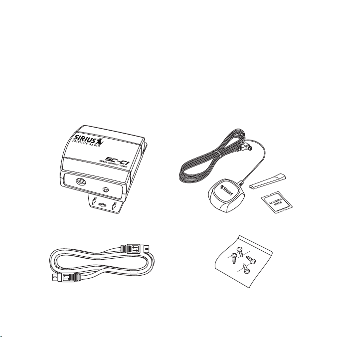
The following items are included with your purchase of the SIRIUS SCC1 SiriusConnect Vehicle Tuner. Unpack the kit carefully and make sure that everything shown is
present. If anything is missing or damaged, or if the unit fails to operate properly, notify
your dealer immediately. It is recommended that you retain the original carton and
packing materials in case you need to ship your kit in the future.
SCC1 Vehicle Tuner
(with mountin g plate attached )
Siriu sConnect Interfa ce Cable
(Male /Male)
Mini- magnetic antenna with 21 ’ cable,
tail cover an d alcoho l pad
Mount ing scre ws
(x4)
[ Pack age Con ten ts ]
7
Page 8
Connections
6
7
3
1
4
8
1 Battery
2 Power Enable
3 Serial Data (RX)
4 Ground
5 Audio Right
6 Serial Data (TX)
7 Audio Ground
1 Audio Left
5
2
Figur e 1
Figur e 2
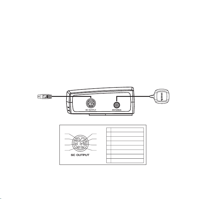
Connector Information
Figure 1 identifies and describes the connectors on the SCC1 Vehicle Tuner. Figure 2
identifies the 8-pin pin-out configuration.
SC O UTPUT: Connection for the SC Interface Cable.
•
ANTE NNA: Connection for the satellite antenna.
•
Conne ct to Sir ius-Ready
Headu nit or Si riusConnec t
Inter face Tran slator
Note 1: The Serial Data TX and RX li nes in the Siri usConne ct Inte rface c able ar e crosse d.
Note 2: The Audio o utput is 1volt RM S.
8
[ Conn ect ions ]
Page 9

Basic system wiring options
Syste m 1
Syste m 2
Syste m 3
The SCC1 SiriusConnect Vehicle Tuner is designed to work with any Sirius-Ready
or SAT Radio Ready headunit. Some headunits will require the use of a SiriusConnect Interface Translator. Please consult your headunit manufacturer for more details
concerning compatibility and interface availability. The SCC1 can also be integrated
in select factory audio systems. Please consult your retailer for interface compatibility
options.
SiriusC onnect 8-pin DIN Cable
Sirius -Ready o r SAT Rad io Ready headunit with a S iriusConn ect 8-pi n DIN con nector. N ote that the head unit must be
capabl e of dir ectly com municatin g to the SCC1 tun er protoc ol.
Headuni t cable to S iriusConnect Interface Cable
Sirius -Ready o r SAT Rad io Ready headunit with an optional headunit specific connecto r/adapte r. Note t hat the h eadunit
must b e capabl e of dire ctly comm unicatin g to the SCC1 tune r protoc ol.
Headuni t bus cable SiriusC onnect Cable
Sirius -Ready, SAT Radio Ready or select OEM headu nits with optiona l SiriusC onnect In terface translato r.
Optional
SiriusCo nnect
Interfac e
[ Conn ect ions ]
9
Page 10

Installation
AN
T
EN
N
A
S
C
O
U
T
P
U
T
Installing the SCC1 Vehicle Tuner
It is recommended that prior to starting the installation, you thoroughly read this
manual and follow the guidelines listed below.
Consider the mounting location carefully. You should make sure that you avoid the
following:
Any location where the tuner is exposed to moisture.
•
Any location where the unit is exposed to extreme heat.
•
Any location where the tuner cannot get adequate ventilation.
•
Any location that would interfere with moving parts on the vehicle or hamper driving.
•
Moun ting t he SCC 1 Tuner
Be sure that you find a location that is flat and has
clearance above the unit to prevent any damage as
well as allowing for ventilation.
Caut ion: If you are attaching the unit directly to the
vehicle’s chassis, be sure that you check to make
sure the area behind the unit is free from moving
parts, fuel or brake lines, wire harnesses, or any
other items which may get damaged by drilling a
mounting hole or using the supplied screws.
[ Inst all atio n ]
10
Page 11

Alternate Mounting Methods
Figur e 3
Figur e 4
Figur e 5
The mounting plate can be removed allowing the
SCC1 to be mounted directly to a surface using
either double-sided stick tape, hook and loop, or
other adhesive material. Simply remove the 2
screws on the bottom of the SCC1 tuner to remove
the bracket, as shown in Figure 3 (right). If using
adhesive material, avoid covering the SID label.
Comb ining with a Sir iusConnect Inter face Device
Some third-party interfaces are designed with the same asymmetrical chassis as the
SCC1. To connect the units together, simply remove the mounting brackets from each
unit, rotate them 90° and connect as shown in Figures 4 and 5 below.
[ Inst all atio n ]
11
Page 12

Mounting the Magnetic Antenna
The installation of the magnetic antenna consists of two installation steps:
Mounting the magnetic antenna and cover/tail on the vehicle
•
Routing the antenna cable through the vehicle to the tuner
•
The magnetic mount antenna has a strong magnetic mount designed to hold the
antenna in place during normal driving conditions (highway/city). This also allows for
easy removal for transferring the antenna to other vehicles.
Figure 6 shows the optimal mounting location for the antenna on several types of
vehicles. These mounting positions should be observed when installing the antenna:
Seda n/Coupe/SUV/Mini -Van: Install the antenna at the rear center of the roof,
•
near the rear window.
Pick up Truck: Install the antenna at the front center of the roof, near the wind-
•
shield.
Conv ertible: Install the antenna at the front center of the trunk lid, near the rear
•
window.
The antenna needs to have an unobstr ucted area of 3 inches by 3 inch es around it.
It is important to mount the antenna where no obstructions will block the antenna from
receiving the SIRIUS signal. Objects which can obstruct the antenna could be a roof
rack, a sunroof, a roof mounted cargo container, another antenna, etc. If your vehicle
has a potential obstruction, be sure that the SIRIUS antenna is mounted at least 3
inches away from it (but no closer than 3 inches from the roof edge, or trunk lid in the
case of a convertible).
[ Inst all atio n ]
12
Page 13

Moun ting t he Ant enna on the Vehic le
Figur e 6Figur e 6
Sedan /CoupeSedan /Coupe
Picku p TruckPicku p Truck
SUV/M ini-VanSUV/M ini-Van
Conve rtibleConve rtible
Follow this procedure to mount the antenna:
Select an appropriate mounting position for your type of vehicle that has an
1.
unobstructed area of 3 inches by 3 inches around the antenna.
Attach the rubber cover/tail to the antenna, as shown in Figure 7, and press the
2.
antenna cable into the rubber cover/tail. The rubber cover/tail will help to position
the antenna the correct distance from the edge of the roof or trunk lid.
Clean the surface area of the vehicle where you will be installing the antenna with
3.
the alcohol prep pad.
Peel the protective material from the adhesive strips (Figure 7) and press the
4.
rubber cover/tail firmly into place on the vehicle (Figure 8).
[ Inst all atio n ]
13
Page 14

Rubber Cover/Tail
Protective Material
Adhesive Strips
Strain Relief
Antenna Cable
Double check that the location of the antenna and rubber cover/tail are correct,
Figur e 7Figur e 7
Figur e 8Figur e 8
5.
and continue to press firmly down on rubber cover/tail for another 30 seconds.
At room temperature (68 degrees), maximum adhesion usually occurs within 72
hours. During this period, avoid car washes and other contact with the antenna
and rubber antenna cable cover/tail.
14
[ Inst all atio n ]
Page 15

Ante nna Ca ble Ro uting
1. Fe ed Cable Un der
Rubber Molding
A round Windo w
4. Rou te Cable fr om Trunk
Un der Interio r Trim, int o
Ca bin and Tow ards Front
of Vehicle
6. Br ing Cable T o
T uner and
Conne ct
t o the Tuner
5. Bri ng Cable ou t from
Tr im and Rout e Under
Ca rpet to Das hboard
2. Rou te Cable Ou t of
Wi ndow Moldin g and
In to Weathers tripping
Ar ound Trunk Opening
3. Rou te Cable Al ong
Tr unk Wall an d Into
Ca bin
Figur e 9Figur e 9
When you have successfully mounted the antenna on the vehicle, you can begin the
cable routing portion of the installation. Separate antenna cable routing procedures
are provided for each type of vehicle:
Seda n/Coupe on page 15
•
Pick up Truck on page 16
•
SUV/ Mini-Van on page 17
•
Conv ertible on page 18
•
Seda n/Coup e Ante nna Cable R outing Proce dure
Figure 9 shows how the antenna cable can be routed from the antenna to the tuner
in a sedan/coupe. The exact routing of the antenna cable may vary depending upon
where you have installed the dock in your vehicle. Avoid side airbag locations on back
pillars and above the doors. (Airbag locations are marked with “SRS” logos.)
[ Inst all atio n ]
15
Page 16

1. Rou te Cable
Un der Rubber
Mo lding Aroun d
Wi ndshield
2. Con tinue Tucki ng Cable
Un der Molding to
Bo ttom of Win dshield
3. Rou te Cable Ou t of Moldin g
an d Into Weat herstrippin g
Ar ound Door O pening.
Co ntinue to B ottom of
Do or Opening.
4. Bri ng Cable ou t from
We atherstripp ing and
Ro ute Under C arpet.
5. Bri ng Cable to the
Tu ner
and C onnect
to the Tuner
Figur e 10Figur e 10
Pick up Tru ck Ant enna Cable Routin g Proc edure
Figure 10 shows how the antenna cable should be routed from the antenna to the
tuner in a pickup truck. The exact routing of the antenna cable may vary depending
upon where you have installed the dock in your vehicle. Avoid side airbag locations on
back pillars and above the doors. (Airbag locations are marked with “SRS” logos.)
16
[ Inst all atio n ]
Page 17

SUV/ Mini-V an Ant enna Cable Routin g Proc edure
1. Fe ed Cable U nder
Rubber Seal Arou nd
Hatch Opening
3. Ro ute Cable
Under Carpet
to Das hboard
4. Br ing Cable to the
T uner and C onnect
t o the Tune r
2. Rou te Cable U nder
In terior Tri m, into
Ca bin and To wards
Fr ont of Veh icle
Figur e 11Figur e 11
Figure 11 shows how the antenna cable should be routed from the antenna to the tuner in an SUV or a Mini-Van. The exact routing of the antenna cable may vary depending
upon where you have installed the dock in your vehicle. Avoid side airbag locations on
back pillars and above the doors. (Airbag locations are marked with “SRS” logos.)
[ Inst all atio n ]
17
Page 18

6. Br ing Cable t o the
T uner
and C onnect
t o the Tuner
1. Bri ng Cable fr om
An tenna Into Inside
of Trunk Lid
2. Tap e Cable Alo ng
In side of Lid to
Hi nge Strut
4. Rou te Cable fr om Trunk
Un der Interio r Trim, int o
Ca bin and Tow ards Front
of Vehicle
5. Bri ng Cable ou t from
Tr im and Rout e Under
Ca rpet to Das hboard
3. Tie Cable to H inge Strut, Allowing
Sl ack for Lid to Open an d Close.
Ro ute Cable I nto Cabin
Th rough Exist ing Wire
Ch annel.
Figur e 12Figur e 12
Conv ertibl e Ante nna Cable R outing Proce dure
Figure 12 shows how the antenna cable should be routed from the antenna to the
tuner in a convertible. The exact routing of the antenna cable may vary depending upon
where you have installed the dock in your vehicle. Avoid side airbag locations on back
pillars and above the doors. (Airbag locations are marked with “SRS” logos.)
18
[ Inst all atio n ]
Page 19

Operation
Activating Your SCC1 Tuner
You must activate the SCC1 tuner before you can begin to receive the SIRIUS Satellite Radio Service.
In order to activate your radio subscription, you will need the SIRIUS ID (SID) which
uniquely identifies your tuner. The SID can be found on a sticker located on the SCC1
packaging, or on the bottom of the SCC1 itself. When you have located the SID, write
it down in the space provided near the end of this manual and store it for future reference.
The SID can also be recalled from your Sirius-Ready headunit. Most units will display
the SID on either Channel 0 or on Channel 255. Please consult your headunit owners
manual or user guide for specific details.
Power on your system and make sure that you are receiving good signal and that you
are able to hear audio on the SIRIUS Preview channel, Channel 184.
Have your credit card handy and contact SIRIUS on the Internet at:
http s://activate.sir ius.radio.com/
and follow the prompts to activate your subscription. You can also call SIRIUS toll-free at:
1-888 -539-SIRIUS (1-8 88-539-7474)
Once the tuner is activated, you will be able to begin enjoying SIRIUS Satellite Radio’s
digital entertainment, and can tune to other channels.
Operation Information
Consult the owners manual for your Sirius-Ready headunit or SiriusConnect Interface
for operating instructions.
[ Oper ati on ]
19
Page 20

Specifications
Operation Frequencies . . . . . . . . . . . . . . . . . . . . . . . . . . . . . . . . . . . . . . . . . . . . . . . . . . .
Satellite . . . . . . . . . . . . . . . . . . . . . . . . . . . . . . . . . . . . . . . . . . 2322.293/2330.207 MHz
Terrestrial . . . . . . . . . . . . . . . . . . . . . . . . . . . . . . . . . . . . . . . . . . . . . . . . . . 2326.250MHz
Power Requirements . . . . . . . . . . . . . . . . . . . . . . . . . . . . . . . 12 Volts DC (1Amp MAX),
Operation Temperature . . . . . . . . . . . . . . . . . . . . . . . . . . -20° to +85° C (-4° to 185° F)
Audio Output . . . . . . . . . . . . . . . . . . . . . . . . . . . . . . . . . . . . . . . . . . . . . . . . . . . 1V (R MS)
Signal-to-noise (S/N) . . . . . . . . . . . . . . . . . . . . . . . . . . . . . . . . . . . . . Greater t han 75dB
Receiver Dimensions (SCC1 only) . . . . . . . . . . 86.7mm x 88.7mm x 33.2m m (WxHxD)
Receiver Weight (with packaging). . . . . . . . . . . . . . . . . . . . . . . . . . . . . . . . . . . . . . 520g
Receiver Weight (SCC1 only) . . . . . . . . . . . . . . . . . . . . . . . . . . . . . . . . . . . . . . . . . 120g)
Receiver Weight (SCC1 with Mounting Bracket) . . . . . . . . . . . . . . . . . . . . . . . . . . 180g)
Antenna Type . . . . . . . . . . . . . . . . . . . . . . . . . . . . . . . . . . . . . . . . . . . . . . . . . .Automotive
Antenna Cable Length . . . . . . . . . . . . . . . . . . . . . . . . . . . . . . . . 21’ (sing le micro-cable)
Antenna Connector Type . . . . . . . . . . . . . . . . . . . . . . . . . . . . . . . . . . . . . . . . . . . . . . SMB
[ Spec ifi cati ons ]
20
Page 21

SIRIUS ID
Write down the SIRIUS ID (SID) of your SCC1 Tuner in the space provided below.
SID:
[ SIRI US ID ]
21
Page 22

Page 23

Page 24

siriu s .com
SIRIUS Satellite Radio Inc.
1221 Avenue of the Americas
New York, NY 10020
800.869. 5590
SCC1 (SCC1092407b)
OO.ABCD1.001
 Loading...