

Page 1
User Guide
SIRIUS CONNECT™ TUNER
Page 2

Congratulations on your purchase of the SIRIUS Connect
SCH1P2 Satellite Radio Tuner!
Your new SCH1P2 SIRIUS Connect Satellite Radio Tuner is designed to work with
SIRIUS-Ready receivers. Check the SIRIUS website for model compatibility.
For the latest information about this and other SIRIUS products and accessories, visit
http://www.sirius.com.
Page 3

Table of Contents
TABLE OF CONTENTS . . . . . . . . . . . . . . . . . . . . . . . . . . . 3
COPYRIGHTS & TRADEMARKS . . . . . . . . . . . . . . . . . . . . . .4
WARNING AND SAFETY INFORMATION . . . . . . . . . . . . . . . . . . . 5
FCC Information . . . . . . . . . . . . . . . . . . . . . . . . . . . . 5
Canadian Compliance . . . . . . . . . . . . . . . . . . . . . . . . . . 6
Safety Precautions . . . . . . . . . . . . . . . . . . . . . . . . . . . . 6
PACKAGE CONTENTS . . . . . . . . . . . . . . . . . . . . . . . . . . . 7
CONNECTORS . . . . . . . . . . . . . . . . . . . . . . . . . . . . . . 9
INSTALLATION . . . . . . . . . . . . . . . . . . . . . . . . . . . . . 11
Mounting the SCH1 Tuner . . . . . . . . . . . . . . . . . . . . . . . . 12
Installing the Outdoor Antenna . . . . . . . . . . . . . . . . . . . . . . . 12
Wiring the SCH1 Tuner . . . . . . . . . . . . . . . . . . . . . . . . . . 24
Subscribing to the SIRIUS Service . . . . . . . . . . . . . . . . . . . . . 26
OPERATION . . . . . . . . . . . . . . . . . . . . . . . . . . . . . . 27
SPECIFICATIONS . . . . . . . . . . . . . . . . . . . . . . . . . . . . 28
SIRIUS ID . . . . . . . . . . . . . . . . . . . . . . . . . . . . . . . 29
[ Tabl e o f Co nte nts ]
3
Page 4

Copyrights & Trademarks
© 2008 Sirius Satellite Radio Inc. All Rights Reserved.
® “SIRIUS”, the SIRIUS dog logo, channel names and logos are trademarks of Sirius
Satellite Radio Inc. All Rights Reserved.
™ “SiriusConnect” is a trademark of Sirius Satellite Radio Inc.
Hardware, subscription, and activation fee required. For full Terms & Conditions, visit
http://sirius.com. Prices and programming are subject to change. Not available in HI
and AK. Equipment and subscription sold separately. Installation required with some
equipment.
[ Copy rig hts & T rade mar ks ]
4
Page 5
Warning and Safety Information
FCC Information
This device complies with part 15 of the FCC Rules. Operation is subject to the following two conditions:
1. This device may not cause harmful interference, and
2. This device must accept any interference received, including interference that
may cause undesired operation.
Note: This equipment has been tested and found to comply with the limits for
a CLASS B digital device, pursuant to Part 15 of the FCC Rules. These limits
are designed to provide reasonable protection against harmful interference
when the equipment is operated in a commercial environment. This equipment
generates, uses, and can radiate radio frequency energy and, if not installed
and used in accordance with the instructions, may cause harmful interference
to radio communications. However, there is no guarantee that interference will
not occur in a particular installation. If this equipment does cause harmful interference to radi o or television reception, which can be determined by turning the
equipment off and on, the user is encouraged to try to correct the interference
by one or more of the following measures:
1. Reorient or relocate the receiving antenna.
2. Increase the separation between the equipment and the receiver.
3. Connect the equipment into an outlet on a circuit different from that to
which the receiver is connected.
4. Consult the dealer or an experienced radio/TV technician for help.
WARN ING
Changes or modifications not expressly approved by the manufacturer could void the
user’s authority to operate the equipment.
[ Warn ing and Sa fety In formati on ]
5
Page 6

Canadian Compliance
This Class B digital apparatus complies with Canadian ICES-003.
Cet appareil numérique de la classe B est conforme à la norme NMB-003 du Canada.
Safety Precautions
Be sure to observe the following warnings. Failure to follow these safety instructions
and warnings may result in a serious accident and/or personal injury.
Install the cables and wiring so that it is not crimped or pinched by screws or
•
sharp metal edges. Route the cables away from moving parts or sharp pointed
edges. This will prevent crimping and damage to the wiring. If the wiring must pass
through a metal hole, be sure to use a rubber grommet to prevent the wire’s insulation from being cut by the metal edge of the hole.
Do not open, disassemble or alter the unit in any way. Doing so may result in fire,
•
electric shock or product damage.
Do not insert any objects into the unit. Doing so may result in fire, electric shock or
•
product damage.
Do not install the unit to high levels of humidity, moisture or dust. Doing so can
•
result in electric shock or product failure.
[ Warn ing and Sa fety In formati on ]
6
Page 7
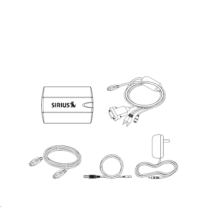
Package Contents
The following items are included with your purchase of the SCH1P2. Unpack the kit
carefully and make sure that everything shown is present. If anything is missing or
damaged, or if the kit fails to operate properly, notify your dealer immediately. It is recommended that you retain the original carton and packing materials in case you need
to ship your kit in the future.
SCH1 SIRIUS C onnect T unerSCH1 SIRIUS C onnect T uner
DIN C ableDIN C able
RG-17 4 Adapte r CableRG-17 4 Adapte r Cable
RS232 Adapter CableRS232 Adapter Cable
AC Po wer Adap terAC Po wer Adap ter
[ Pack age Con ten ts ]
7
Page 8
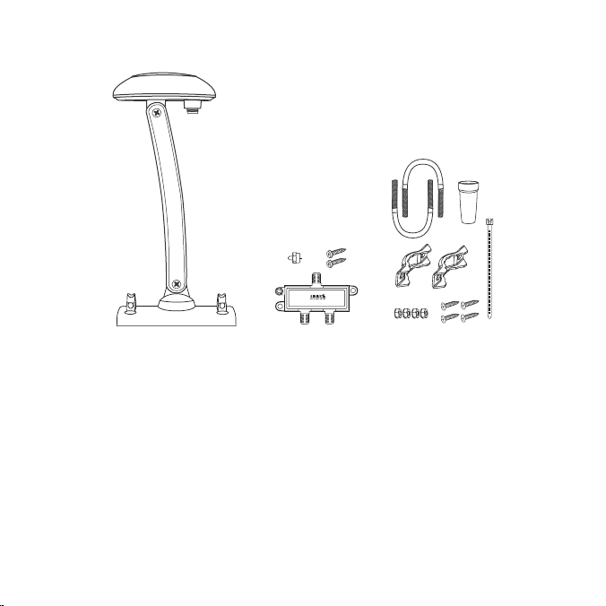
[ Pack age Con ten ts ]
8
Outdo or Anten na and A ntenna I nstallat ion Item sOutdo or Anten na and A ntenna I nstallat ion Item s
Page 9
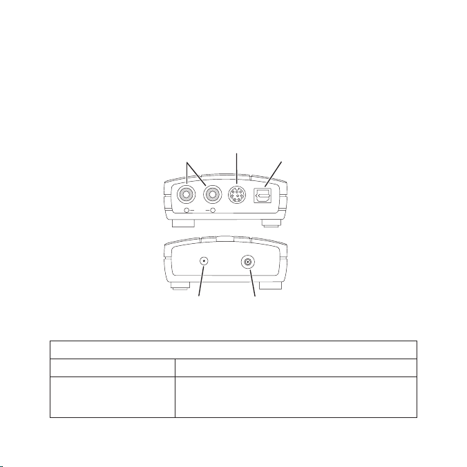
Connectors
AUDIO
OUT
8 PIN
OPTICAL
R L
DC 5V
ANT
Audio
Connectors
L/R
Optical
Audio
Connector
DIN
Connector
AC Adapter
Connector
Indoor/Outdoor
Antenna
Connector
Figur e 1Figur e 1
Figure 1 and the table following identify and describe the connectors of the SCH1
Tuner.
Desc ription of the S CH1 Connectors
Conn ector Desc ription
L/R audio connection for RCA-type audio cables.
Audi o Connector L/R
(Optional, cable not provided.) (Used when audio is
not provided via the DIN cable.)
[ Conn ect ors ]
9
Page 10
Desc ription of the S CH1 Connectors
Conn ector Desc ription
DIN Connector
Opti cal Audio Connec tor
AC A dapter Connector
Indo or/Outdoor Anten na
Conn ector
[ Conn ect ors ]
10
Connection for the DIN cable to the SIRIUS-Ready
receiver.
Audio connection when using an optical cable. (Optional, cable not provided.) (Used when audio is not
provided via the DIN cable.)
Connection for the AC Power Adapter. Note that the
AC Power Adapter is used only when your SIRIUSReady receiver does not supply power to the tuner via
the DIN cable connection.
Connector for the Indoor/Outdoor Antenna.
Page 11

Installation
It is recommended that prior to starting the installation, you read this installation section completely and follow the instructions. In addition, consult the manual of the audio
device to which you will be connecting the SCH1 Tuner to determine the required
installation configuration.
The SCH1 Tuner can be connected to a SIRIUS-Ready receiver using the DIN cable,
or by using the provided RS-232 Adapter Cable.
When connecting using a DIN cable:
If power for the SCH1 Tuner is not provided by your audio device via the DIN cable
•
connection, you will need to use the provided AC Power Adapter to provide power
for the SCH1 Tuner.
If audio input from the SCH1 Tuner is not supported via the DIN cable connection
•
of your audio device, you will need to connect the audio output of the SCH1 Tuner
to your audio system via the RCA-type or Optical audio output connectors of the
tuner. (You will need to purchase the appropriate cable separately.)
When connecting using the RS-232 Adapter Cable:
The AC Power Adapter must be connected to the power connector on the RS-232
•
Adapter Cable.
Note : Do not connect the AC Power Ad apter to the SCH 1 Tuner when us-
•
ing the RS-232 Adapt er Cable.
The maximum length of RG-6 cable between the Outdoor Antenna and the SCH1
Tuner is 50 ft. For longer lengths the Splitter/Amplifier must be used. When the Splitter/Amplifier is used, the maximum lengths of RG-6 cable are 100 ft. from the Outdoor
Antenna to the Splitter/Amplifier, and 50 ft. from the Splitter/Amplifier to the SCH1
Tuner. (Refer to Figures 15 & 16.) RG-6 cable(s) are not provided.
[ Inst all atio n ]
11
Page 12

SCREW
MOUNTING SLOTS
Figur e 2Figur e 2
Mounting the SCH1 Tuner
Consider the mounting location carefully to be sure that you avoid the following:
Any location where the tuner is exposed to moisture.
•
Any location where the tuner is exposed to extreme heat.
•
The tuner may be mounted on a wall with #10 screws, using the slots on the underside of the tuner to hang on the tuner on the screws. (Figure 2) Alternately, the tuner
may placed on any flat surface.
Installing the Outdoor Antenna
Before installing the indoor/outdoor antenna, read this entire section. To ensure consistent reception of the SIRIUS signal it is important that the antenna be installed and
oriented according to these installation instructions.
Dete rminin g a Lo cation for the An tenna
For correct operation and best reception of the SIRIUS signal, it is important that the
[ Inst all atio n ]
12
Page 13

outdoor antenna is located in a place where it will have a clear view of the SIRIUS
No obstructions to the
sky within this area
Figur e 3Figur e 3
satellites in the sky. Obstructions such as bushes, trees, other homes or buildings,
overhangs, soffits, chimneys, gables, dormers, etc., will impair or prevent the antenna
from receiving a signal.
The best reception is obtained if the pod portion of the antenna (where the SIRIUS
logo is printed) has a clear 360 degree view of the sky within the cone-shaped area
shown in Figure 3.
If you cannot obtain a clear 360 degree view of the sky, then you must at least have a
clear view of the sky in the direction of the SIRIUS satellites, as shown in the following
map diagram.
[ Inst all atio n ]
13
Page 14

1
2
3
4
5
HORIZON
SKY
SOUTH
WEST EAST
NORTH
Use the above map and find the area you are located in (1 to 5). Then find the direc-
Figur e 4Figur e 4
tion in which you need to have a clear view of the sky:
Area 1: You will need a location with a clear view of the sky facing EAST or
NORT HEAST or SOUTHEA ST
Area 2: You will need a location with a clear view of the sky facing NORTH or
NORT HEAST
Area 3: You will need a location with a clear view of the sky facing NORTH or
NORT HWEST
Area 4: You will need a location with a clear view of the sky facing WEST or
NORT HWEST or SOUTHWE ST
Area 5: You will need a clear view of the sky facing STRAIGHT UP
14
[ Inst all atio n ]
Page 15

Choose a mounting location for the antenna which has an unobstructed view of the sky
No obstructions to the
sky within the area facing
North to Northeast
N
W E
S
NORTH
Figur e 5Figur e 5
in the direction for your area.
For example, suppose you live in Are a 2. You determined that your antenna will need
to have a clear view of the sky facing North or Nort heast. The exact direction is
determined by your specific location in Area 2 relative to the X on the map: If you live
in T exas, you will need a more North facing clear view of the sky whereas if you live in
sout hern California, you will need a more Northeast facing clear view of the sky.
Figure 5 shows a correct antenna installation for Ar ea 2, with a clear view of the sky in
the North to Northea st direction.
[ Inst all atio n ]
15
Page 16

MOUNTING
HOLES
Figur e 6Figur e 6
Ante nna Mo unting Options
There are three possible mounting options for the outdoor antenna, and the antenna
mounting location you have chosen may determine which mounting methods you can
use:
Wall Mount: Mounting the antenna directly on the side of a home or building.
•
Roof Mount: Mounting the antenna on the roof of a home or building.
•
Mast Mount: Mounting the antenna on a mast or pole, such as an existing satellite
•
TV dish mast, an existing TV antenna mast, or other mast or pole, not exceeding 2
inches in diameter.
Wall Mount
The antenna mounting bracket should be oriented in a vertical position (Figure 6) and
mounted directly to the wall of the building or home using the provided #10 screws.
Remember to avoid blocking the antenna’s view of the sky as described in the previous section by locating the antenna too high under the eaves or soffit of the home or
building. Refer to Figure 7.
[ Inst all atio n ]
16
Page 17

UNOBSTRUCTED
VIEW OF THE SKY
INCORRECT CORRECT
UNOBSTRUCTED
VIEW OF THE SKY
CORRECT
OBSTRUCTED
Once you have determined a suitable mounting location, use the mounting bracket as
Figur e 7Figur e 7
a template and mark the wall with the location of the four screw holes in the bracket.
Then, using a 3/32 in. drill bit, drill pilot holes in the wall for the screws and then
screw the bracket to the wall.
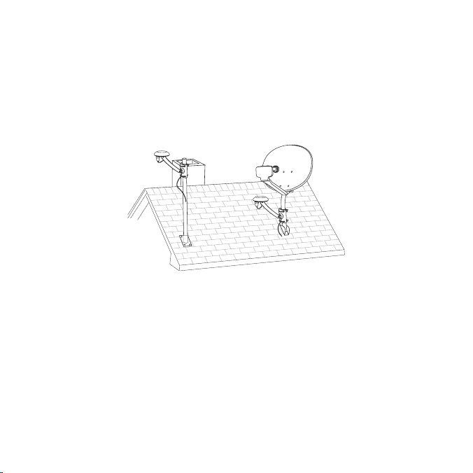
Roof Mount
When mounting the antenna on the roof of a home or building, mount the antenna as
close as possible to the peak of the roof. It can be mounted on the chimney or on the
soffit of the home or building. Do not mount it directly on the roof surface to avoid
leaks. Remember to avoid blocking the antenna’s view of the sky by locating it where a
chimney, dormer, gable, etc., may obstruct the view of the sky.
[ Inst all atio n ]
17
Page 18

MOUNTING
HOLES
Figur e 8Figur e 8
Figur e 9Figur e 9
The antenna mounting bracket should be oriented in a vertical position as shown in
Figures 8 and 9, and mounted directly to the building or home using the provided #10
screws.
Once you have determined a suitable mounting location, use the mounting bracket as
a template and mark the mounting surface with the location of the four screw holes in
the mounting bracket. Then, using a 3/32 in. drill bit, drill pilot holes for the screws. It
may be necessary to fill the holes with a small amount of roof cement or caulk to insure
a watertight installation. Screw the bracket to the mounting surface using the provided
#10 screws.
[ Inst all atio n ]
18
Page 19
Mast Mount
Figur e 10Figur e 10
The outdoor antenna can be mounted on most any mast or pole which does not
exceed 2 inches in diameter using the provided U-bolts and mounting brackets,
as shown in Figure 10. If you have a satellite TV dish, the outdoor antenna may be
mounted on the same mast as the satellite dish, but remember that the dish cannot
obstruct the antenna’s view of the sky in the direction which you determined from the
map in the previous section.
To mount the antenna to the mast, you will need to use the two provided U-bolts, the
two mounting brackets, and the four hex nuts. Keep in mind that the antenna cable is
routed under the lower U-bolt, in the slot provided in the antenna base as shown in
Figure 11.
[ Inst all atio n ]
19
Page 20

Figur e 11Figur e 11
Figur e 12Figur e 12
Slide one of the U-bolts through the holes at the top of the mounting bracket. Then slide
one of the mounting brackets over the two legs of the U-bolt as shown in Figure 12.
Next, screw the hex nuts on each leg until they are snug. Do not yet tighten the hex
[ Inst all atio n ]
20
Page 21

nuts beyond finger tight. Repeat this procedure with the other U-bolt. When all the hex
1
Antenna Pod
HORIZONTAL LEVEL
SKY
Adjustment
Screw
Adjustment
Screw
2
Figur e 13Figur e 13
nuts are snug, verify that the antenna is facing the correct direction and begin tightening each hex nut with a 3/8” wrench. Turn each hex nut one-half turn and then move
to the next hex nut repeating this one-half turn pattern until all the hex nuts are equally
tight. Tighten the hex nuts enough so that the antenna is secured to the mast or pole,
but do not overtighten them.
Adju sting and Ai ming the An tenna
The pod portion of the antenna (where the SIRIUS logo is printed) needs to be
adjusted and aimed so that it is level and horizontal to the sky. There are two possible
adjustments that may be made on the antenna to accomplish this: tilting the antenna
pod itself (1), and adjusting the antenna support arm (2), as shown in Figure 13.
Slightly loosen the adjustment screws and position the antenna so that the top of the
[ Inst all atio n ]
21
Page 22

Figur e 14Figur e 14
antenna pod is level, with the top of the pod horizontal to the sky as shown. When
the antenna is adjusted correctly, tighten the adjustment screws but be careful not to
overtighten them.
Take the RG-6 cable and thread one end of the cable through the opening in the end
of the rubber boot as shown in Figure 14. Then connect the cable to the antenna pod
as shown in the illustration following.
Slide the rubber boot over the cable connection to provide a weather proof seal and
install the cable tie around the cable directly below the rubber boot to prevent the rubber boot from slipping down. Trim off the excess cable tie.
Connect the RG-6 cable to the RG-174 adapter cable as shown in Figure 15. For RG6 lengths greater than 50 ft., connect as shown in Figure 16.
Connect the RG-174 Adapter Cable to the SCH1 Tuner ANT connection.
[ Inst all atio n ]
22
Page 23
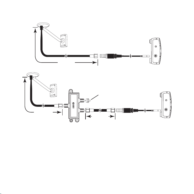
RG-174
RG-6
Adapter Cable
50’ MAX.
DC 5V
ANT
RG-174
RG-6
RG-6
Terminator (or
connect to
second tuner)
Splitter/Amplifier
Adapter Cable
100’ MAX.
50’ MAX.
DC 5V
ANT
IN
OUT1 OUT2
Figur e 15Figur e 15
Figur e 16Figur e 16
Test ing an d Opti mizing the Antenn a Sign al Strength
The stronger the SIRIUS signal strength, the less likely it is that you will experience an
interruption of the audio when listening to a broadcast. To assist you in adjusting the
antenna aiming for optimal reception, the SIRIUS-Ready receiver can display a screen
showing the strength of the SIRIUS signal being received, similar to Figure 17.
To access the antenna aiming or signal indicator screen, consult the user guide which
accompanied your SIRIUS-Ready receiver. The SATELLITE portion of the display
screen (Figure 17) shows the strength of the signal being received from the satellite,
while the TERRESTRIAL portion of the display screen shows the strength of the signal
being received from terrestrial based transmitters, if available.
[ Inst all atio n ]
23
Page 24
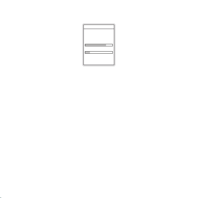
Antenna Aiming
Press BACK when done
SATELLITE
Adjust your antenna
position to maximize signal
strength.
TERRESTRIAL
Figur e 17Figur e 17
Wiring the SCH1 Tuner
The SCH1 Tuner can be wired using the DIN cable connection as shown in Figure 18,
or using the RS232 Adapter Cable as shown in Figure 19.
When connecting using a DIN cable:
If power for the SCH1 Tuner is not provided by your audio device via the DIN cable
•
connection, you will need to use the provided AC Power Adapter to provide power
for the SCH1 Tuner.
If audio input from the SCH1 Tuner is not supported via the DIN cable connection
•
of your audio device, you will need to connect the audio output of the SCH1 Tuner
to your audio system via the RCA-type or Optical audio output connectors of the
tuner. (You will need to purchase the appropriate cable separately.)
When connecting using the RS-232 Adapter Cable:
The AC Power Adapter must be connected to the power connector on the RS-232
•
Adapter Cable.
Note : Do not connect the AC Power Ad apter to the SCH 1 Tuner when us-
•
ing the RS-232 Adapt er Cable.
Please consult your audio equipment manuals for the wiring connections needed for
the SCH1 Tuner to operate with your particular equipment.
[ Inst all atio n ]
24
Page 25

AUDIO
OUT
8 PIN
OPTICAL
R L
DC 5V
ANT
AUDIO OUTPUT L/R
(OPTIONAL, CABLE
NOT INCLUDED)
OPTICAL LINK
(OPTIONAL, CABLE
NOT INCLUDED)
DIN CABLE
TO SIRIUS-READY
RECEIVER
INDICATOR
LIGHT
AC POWER ADAPTER
(OPTIONAL, AC ADAPTER IS
USED ONLY IF POWER IS NOT
SUPPLIED VIA DIN CABLE)
OUTDOOR ANTENNA
AUDIO
OUT
8 PIN
OPTICAL
R L
DC 5V
ANT
RS-232
ADAPTER
CABLE
OUTDOOR ANTENNA
INDICATOR
LIGHT
NOTE: DO NOT CONNECT THE AC POWER
ADAPTER HERE. CONNECT ONLY TO
THE RS-232 ADAPTER CABLE.
RS232 CABLE
TO SIRIUS-READY
RECEIVER
AUDIO OUTPUT
L/R
AC POWER
ADAPTER
Figur e 18Figur e 18
Figur e 19Figur e 19
[ Inst all atio n ]
25
Page 26

Subscribing to the SIRIUS Service
Before you can listen to SIRIUS radio, you need to subscribe to the SIRIUS Satellite
Radio service. To subscribe do the following:
1. Be sure that the SCH1 is correctly installed according to the previous installation
instructions.
2. Refer to the operators guide that accompanied your receiver. Turn the receiver
on and select SIRIUS radio.
3. After the startup sequence, the SCH1 will update the SIRIUS channel line-up. Wait
until the channel updates have completed before pressing any buttons.
4. Once the channels have been updated, the display will change to Ca ll 1- 888-
539- SIRIU S to Subscr ibe and will tune to channel 184. You will not be able to
listen to SIRIUS satellite radio until you activate your SIRIUS subscription.
5. You’ll need to ascertain the SCH1’s unique 12-digit SIRIUS ID number (SID). The
SID number can be found in several places:
On a label on the SCH1P2 packaging
•
On the underside of the SCH1
•
The SID ca n be d isplayed by tunin g to channel 0 .
•
Write down the SID number in the space provided near the end of this manual.
6. Have your credit card handy and contact SIRIUS on the Internet at:
https:/ /activate.sirius radio.com/
and follow the prompts to activate your subscription. You can also call SIRIUS
toll-free at:
1-888-5 39-SIRIUS (1-888-539-7474).
7. When you have successfully subscribed to the SIRIUS service, and the SCH1
has been updated with your subscription information, an alert will be displayed
indicating that the tuner has been subscribed.
You are now ready to begin enjoying SIRIUS Satellite Radio’s digital radio entertainment and traffic service!
[ SIRI US ID ]
26
Page 27

Operation
Consult the owners manual of your SIRIUS-Ready receiver for operating instructions.
The SCH1 Tuner has an indicator light which provides basic status information about
the tuner. When the tuner is first powered on, this light will be red to indicate the
tuner is receiving power. After the tuner is initialized by the Sirius-Ready receiver or
controller:
Stea dy Red: Initial power-on indication.
Flas hing Red: Indicates that the antenna is not connected to the Tuner.
Stea dy Amber: Indicates that the antenna is connected to the Tuner, but no signal
is being received.
Stea dy Green: Indicates that the Tuner is functioning properly and receiving a
good signal.
[ Oper ati on ]
27
Page 28

Specifications
Operational Frequencies
Satellite . . . . . . . . . . . . . . . . . . . . . . . . . . . . . . . . . . . . . . . . .232 2.293/2330.207 M Hz
Terrestrial . . . . . . . . . . . . . . . . . . . . . . . . . . . . . . . . . . . . . . . . . . . . . . . . . 2326.250MHz
Power Requirements . . . . . . . . . . . . . . . . . . . . . . . . . . . . . . . . . . . . . . . . . . . . 5 Volts DC
Dimensions. . . . . . . . . . . . . . . . . . . . . . . . . . . . . . . . . . . . . . . . . 1” x 2.6” x 3.6” (WxHxD)
26mm x 66mm x 92mm (WxHxD)
Antenna Type . . . . . . . . . . . . . . . . . . . . . . . . . . . . . . . . . . . . . . . . . . . . . . . . . . Windowsill
Antenna Cable Length . . . . . . . . . . . . . . . . . . . . . . . . . . . . . . . . .21’ (single micro-cable)
Connector Type . . . . . . . . . . . . . . . . . . . . . . . . . . . . . . . . . . . . . . . . . . . . . . . . . . . . . SMB
Audio Interface. . . . . . . . . . . . . . . . . . . . . . . . . . . . . . RCA-type Stereo L/R Connectors
Optical Link Connector
Audio Output . . . . . . . . . . . . . . . . . . . . . . . . . . . . . . . . . . . . . . . . . . . . . 0.75v, 550 Ohm
Signal to Noise Ratio . . . . . . . . . . . . . . . . . . . . . . . . . . . . . . . . . . . . . . . . . . . . . . . . 80dB
Weight . . . . . . . . . . . . . . . . . . . . . . . . . . . . . . . . . . . . . . . . . . . . . . . . . . . 0.1 kg. (3.5 oz.)
Included Cable . . . . . . . . . . . . . . . . . . . . . . . . . . . . . . . . . . . . . . . . . . . . 8-Pin DIN Ca ble
[ Spec ifi cati ons ]
28
Page 29
SIRIUS ID
Write down the SIRIUS ID (SID) of your SCH1P2 in the space provided below.
SID: ____________________________________
[ SIRI US ID ]
29
Page 30

Page 31

Page 32

siriu s .com
SIRIUS Satellite Radio Inc.
1221 Avenue of the Americas
New York, NY 10020
800.869. 5590
SCH1P (SCH1P061608a)
OO.ABCD1.001
 Loading...