

Page 1
CATV
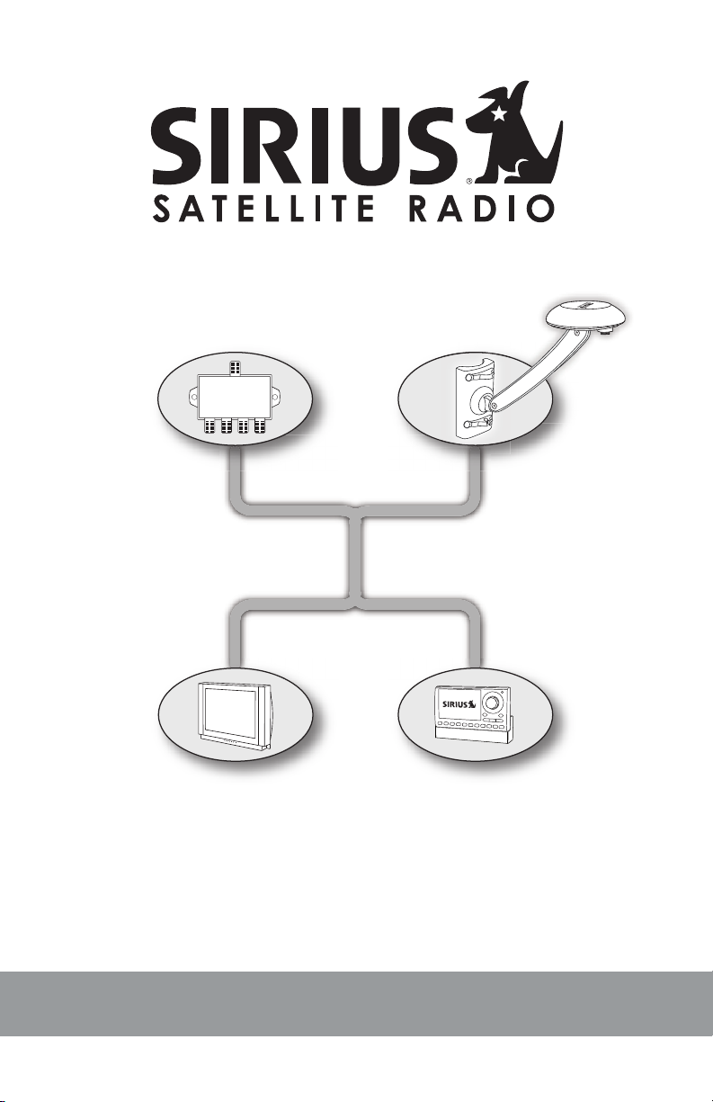
Home Signal Distribution Kit
for Cable TV Plus SIRIUS
For Use With a Single SIRIUS Receiver
Installation Manual
Page 2
Thank you for purchasing the Home Signal Distribution Kit for
A
B
C
F
G
H
I
J
D
E
Cable TV Plus SIRIUS
The Home Signal Distribution Kit for Cable TV Plus SIRIUS will allow you to connect a SIRIUS receiver using your existing cable TV RG-6 wiring. This allows you
great exibility as to where you locate the SIRIUS outdoor antenna and where
you locate your SIRIUS receiver. A short adapter cable is included for adapting
the RG-6 cable to your SIRIUS receiver.
The SIRIUS outdoor antenna is a high-performance antenna, specically designed to receive signals from the SIRIUS satellites and terrestrial (ground) transmitters when mounted outdoors on a home or other building, wall, pole, or roof.
The antenna has been approved by Sirius Satellite Radio to receive the SIRIUS
signal under a variety of conditions within the SIRIUS North American coverage
area.
Installation of the antenna and diplexers requires experience in mechanical and
electrical procedures. Review this installation manual before beginning the installation process. If you are not comfortable or experienced with the installation
procedures, SIRIUS recommends that you have a professional install the kit and
wiring for you.
The antenna should be mounted according to the instructions in this manual to
ensure the best quality reception of the SIRIUS signal. All necessary mounting
hardware for a variety of mounting options is included with this kit.
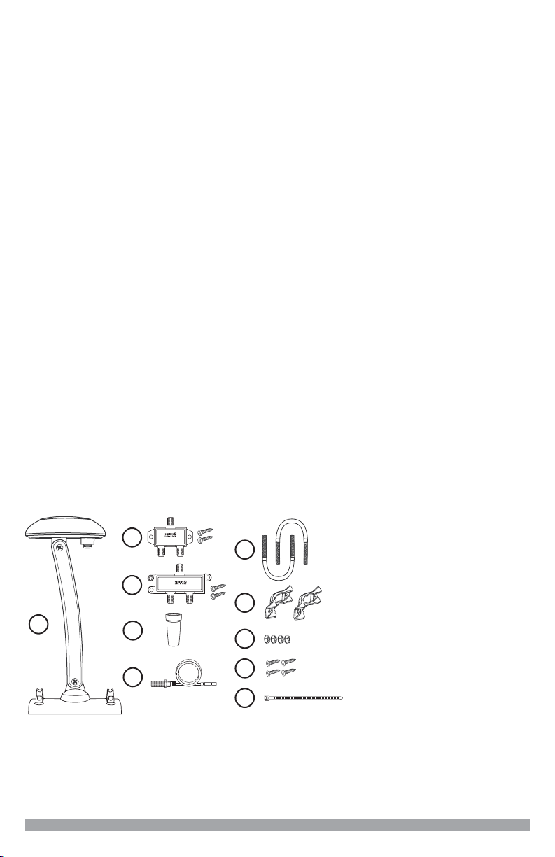
Box Contents
Open the box and verify that all the items shown below are included with the kit.
If any items are missing, please contact your dealer or retailer immediately. Keep
your purchase receipt and the packaging materials should you need to return or
ship the kit.
A. Outdoor Antenna
B. SRD2 Diplexer
C. SRD-2VB Diplexer
D. Rubber Cable Boot
E. RG-174 Adapter Cable
F. U-Bolts (2)
G. Mounting Brackets (2)
H. Hex Lock Nuts (4)
I. #10 Screws (4)
J. Cable Tie
2
Home Distribution Kit Installation Manual
Page 3
Tools Required
IN/OUT
CATV
MODEL SRD-2VB
DIPLEXER
15-2500 MHz
SIRIUS RADIO
POWER PASS
IN/OUT
CATV SIRIUS RADIO
IN/OUT
CATV
MODEL SRD2
DIPLEXER
15-2500 MHz
SIRIUS RADIO
POWER PASS
IN/OUT
CATV SIRIUS RADIO
DIPLEXER MODEL SRD2DIPLEXER MODEL SRD2
DIPLEXER MODEL SRD-2VBDIPLEXER MODEL SRD-2VB
A phillips-type screwdriver and a 3/8 in. wrench is needed for installation. Depending upon the type of installation, a power drill with a 3/32 in. drill bit may also
be required.
Caution and Warnings
WARNING: Be sure not to cut, damage, or puncture the external jacket of the
antenna cables during the installation procedure. Damage to the antenna cable
can cause the SIRIUS signal to be degraded or unavailable, and can also cause
water to intrude into the antenna cable causing the cable to fail.
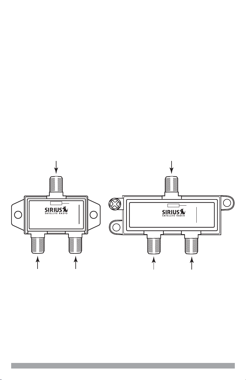
Diplexer and Diplexer Port Identication
For a successful installation, the various cables used in the installation process
described later in this manual must be connected to the correct ports on each
Diplexer. The following illustration identies the two different Diplexers, SRD2 &
SRD-2VB, and the 3 ports on each Diplexer. This diagram should be used for
reference during installation. The SRD-2VB Diplexer must be used nearest to
the SIRIUS receiver.
Home Distribution Kit Installation Manual
3
Page 4
Materials Required and Installation Considerations
Adapter
Cable
DEN
KITCHEN
BEDROOM
GARAGE/
WORKSHOP
SATELLITE
OUTDOOR ANTENNA
SATELLITE RADIO
MASTER BEDROOM
CATV SPLITTER
DIPLEXER SRD-2VB
TV
TV
TV
DIPLEXER SRD2
TV
C
A
T
V
D D
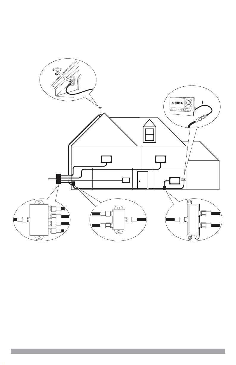
In order to install the antenna you will need to purchase several lengths of RG-6
antenna cables to complete your installation. The following illustration shows a
typical home installation.
A CATV splitter takes the cable TV service that comes into your home and splits
the signal so that cable TV service can be connected two or more TVs in the
different rooms in your home. In this manual, the CATV splitter is depicted as a
4-port splitter, however, the CATV splitter in your home may have 2, 3, 4, or more
ports.
The CATV splitter is usually located near where the cable TV wiring enters your
home, which is typically in a garage, basement, or utility room. You’ll need to
locate your CATV splitter in order to install the Home Distribution Kit.
You may need to purchase up to four separate RG-6 cables of the appropriate
lengths to install your Home Signal Distribution Kit. The number of cables which
will be needed is dependent upon how the existing CATV wiring is installed in
your home. Some homes have exposed, surface mounted CATV wiring while oth-
4
Home Distribution Kit Installation Manual
Page 5
ers have the CATV wiring built into the walls with a CATV connection point in the
RG-6
RG-6
1
EXISTING CATV RG-6 CABLES
CATV Splitter
CATV
D
Diplexer
SRD2
Diplexer
SRD2VB
2
RG-6
RG-174
Adapter Cable
D
6’
3
4
RG-6
Room where SIRIUS Receiver is being Installed
Other Rooms
Vicinity of CATV Splitter
EXISTING CATV
RG-6 CABLING
150
50’ MAX
’
room wall.
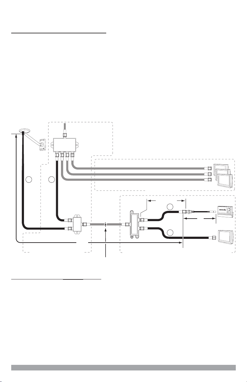
For homes having exposed wiring, cables will be needed for the following:
A length of RG-6 cable to go from the SIRIUS outdoor antenna to the loca-
1.
tion of the rst Diplexer (SRD2).
A length of RG-6 cable to go from the CATV splitter to the rst Diplexer
2.
(SRD2).
A length of RG-6 cable to go from the second Diplexer (SRD-2VB) to your
3.
TV.
A length of RG-6 cable to go from the second Diplexer (SRD-2VB) to your
4.
SIRIUS receiver. The length of this cable should not exceed 50 ft.
The cables which must be purchased are depicted in the following illustration as
solid black, while existing cables are shown as gray.
For homes having hidden wiring, cables will be needed for the following:
A length of RG-6 cable to go from the SIRIUS outdoor antenna to the loca-
1.
2.
3.
tion of the rst Diplexer (SRD2).
A length of RG-6 cable to go from the CATV splitter to the rst Diplexer
(SRD2).
A length of RG-6 cable to go from the CATV wall outlet connector to the
second Diplexer (SRD-2VB).
A length of RG-6 cable to go from the second Diplexer (SRD-2VB) to your
4.
SIRIUS receiver. The length of this cable should not exceed 50 ft.
Home Distribution Kit Installation Manual
5
Page 6
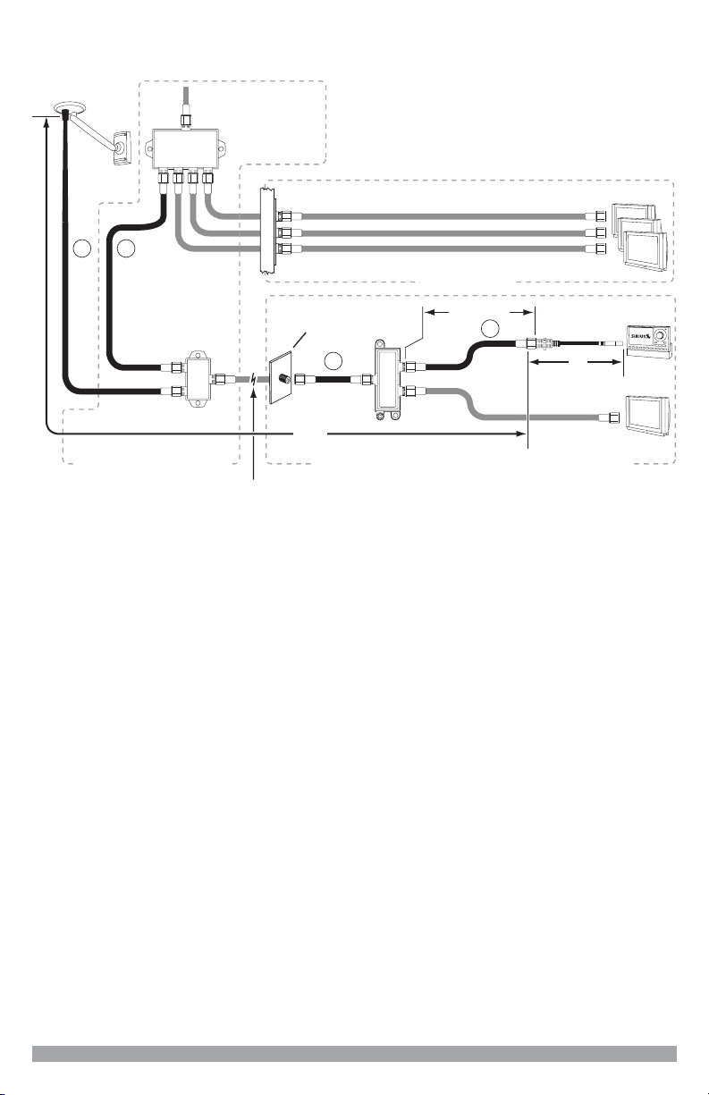
The cables which must be purchased are depicted in the following illustration as
Diplexer
SRD2
Diplexer
SRD-2VB
RG-6
D
RG-6
1
RG-6
Room where SIRIUS Receiver is being Installed
Other Rooms
Vicinity of CATV Splitter
RG-6
EXISTING CATV RG-6 CABLES
EXISTING CATV RG-6
CABLING IN WALLS
CATV WALL
OUTLET
CATV Splitter
CATV
D D
6’
150’
2
4
3
RG-6
WALLWALL
RG-174
Adapter Cable
50’ MAX
solid black, while existing cables are shown as gray.
RG-6 cable is typically sold in short patch lengths, 3 or 6 ft., and longer lengths of
25, 50, or 100 ft., all with “F” type connectors on each end. These cables may be
purchased at your local hardware store, home center, or electronics retailer.
The combined length of the RG-6 cables from the outdoor antenna to the
SIRIUS receiver should not exceed 150 ft., as shown in the preceding illustrations. The overall length for your particular installation may be less than 150
ft.
Determine the overall length of the RG-6 cable run by measuring the distance
from the SIRIUS outdoor antenna mounting location to where the rst diplexer
will be located. (It is recommended that the diplexer be located indoors.) Next
measure the distance from the rst diplexer to where the second diplexer will
be located. Then measure the distance from the second diplexer to the SIRIUS
receiver and note that this particular cable length should not exceed 50 ft. Also
include the length of cable from the CATV wall outlet to the second diplexer if
your home has hidden wiring. The sum of these cable lengths should not
exceed 150 ft.
6
Home Distribution Kit Installation Manual
Page 7
Antenna Installation
No obstructions to the
sky within this area
A successful antenna installation consists of three steps: First, determining a
location for the antenna; Second, choosing a mounting option; and Third, adjusting and aiming the antenna. Please read the following three sections before
beginning the antenna installation so that you understand the entire installation
process.
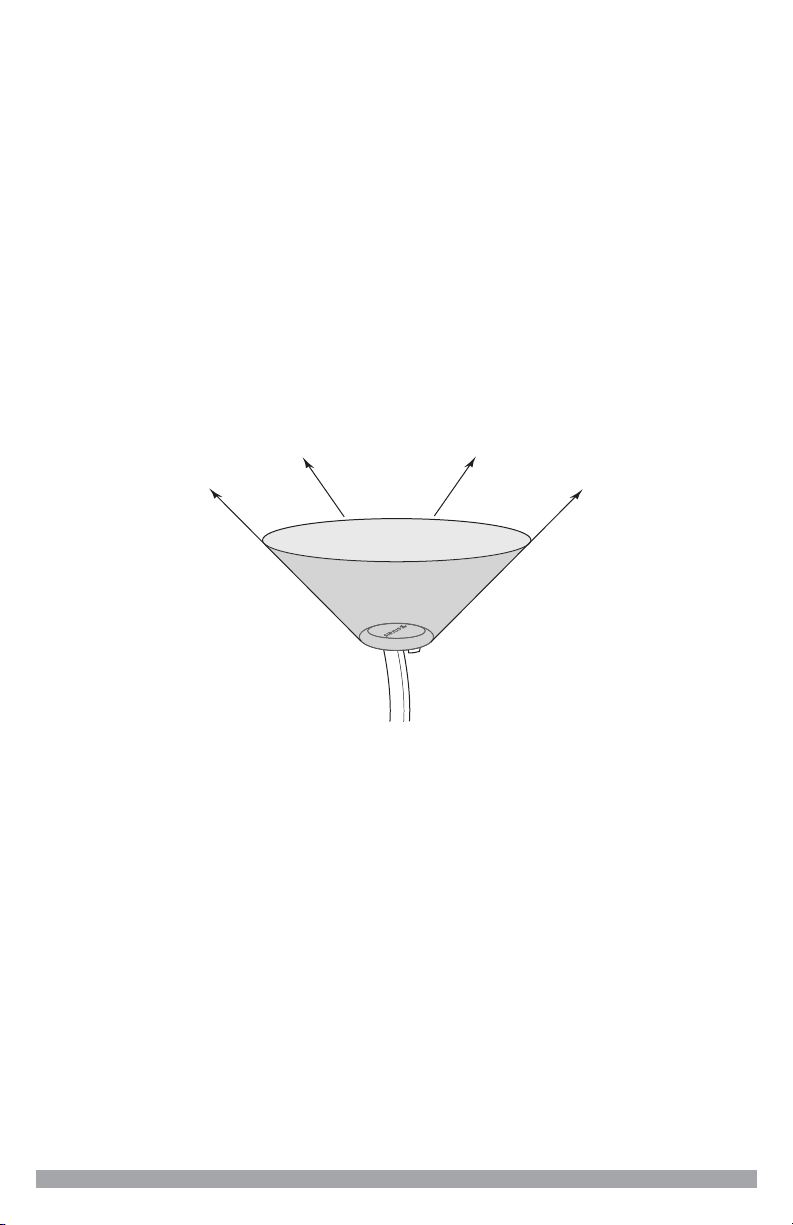
Determining a Location for the Antenna
For correct operation and best reception of the SIRIUS signal, it is important that
the outdoor antenna is located in a place where it will have a clear view of the
SIRIUS satellites in the sky. Obstructions such as bushes, trees, other homes
or buildings, overhangs, softs, chimneys, gables, dormers, etc., will impair or
prevent the antenna from receiving a signal.
The best reception is obtained if the pod portion of the antenna (where the
SIRIUS logo is printed) has a clear 360 degree view of the sky within the coneshaped area shown in the following illustration.
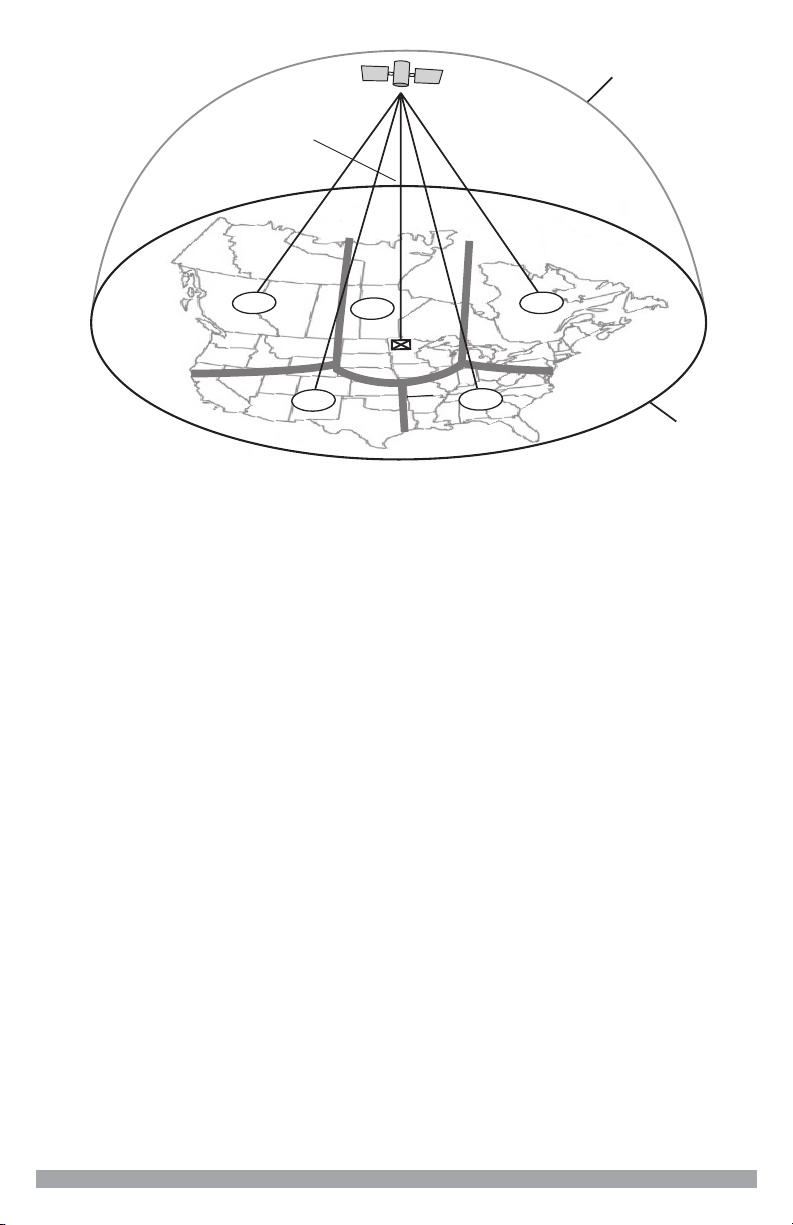
If you cannot obtain a clear 360 degree view of the sky, then you must at least
have a clear view of the sky in the direction of the SIRIUS satellites, as shown in
the following map diagram.
Home Distribution Kit Installation Manual
7
Page 8
1
2
3
4
5
HORIZON
SKY
SOUTH
WEST EAST
NORTH
Use the above map and nd the area you are located in (1 to 5). Then nd the
direction in which you need to have a clear view of the sky:
Area 1: You will need a location with a clear view of the sky facing EAST or
NORTHEAST or SOUTHEAST
Area 2: You will need a location with a clear view of the sky facing NORTH or
NORTHEAST
Area 3: You will need a location with a clear view of the sky facing NORTH or
NORTHWEST
Area 4: You will need a location with a clear view of the sky facing WEST or
NORTHWEST or SOUTHWEST
Area 5: You will need a clear view of the sky facing STRAIGHT UP
Choose a mounting location for the antenna which has an unobstructed view of
the sky in the direction for your area.
For example, suppose you live in Area 2. You determined that your antenna
will need to have a clear view of the sky facing North or Northeast. The exact
direction is determined by your specic location in Area 2 relative to the X on the
map: If you live in Texas, you will need a more North facing clear view of the sky
whereas if you live in southern California, you will need a more Northeast fac-
ing clear view of the sky.
The following illustration shows a correct antenna installation for Area 2, with a
clear view of the sky in the North to Northeast direction.
8
Home Distribution Kit Installation Manual
Page 9

No obstructions to the
sky within the area facing
North to Northeast
N
W E
S
NORTH
Once you have determined a possible mounting location for your area, it is
RG-174
RG-6
Adapter Cable
Signal Indicator
S
i
g
n
a
l
I
n
d
i
c
a
t
o
r
recommended that you put the antenna in place temporarily and connect the
antenna to your SIRIUS receiver as shown in the following illustration. Using the
Antenna Aiming or Signal Indicator feature of your receiver, verify that your antenna is receiving a good SIRIUS signal. (Consult the user guide of the receiver
for specic instructions.)
Antenna Mounting Options
There are three possible mounting options for the outdoor antenna, and the
antenna mounting location you have chosen may determine which mounting
methods you can use:
Wall Mount: Mounting the antenna directly on the side of a home or building.
Roof Mount: Mounting the antenna on the roof of a home or building.
Mast Mount: Mounting the antenna on a mast or pole, such as an existing satel-
lite TV dish mast, an existing TV antenna mast, or other mast or pole, not exceeding 2 inches in diameter.
Home Distribution Kit Installation Manual
9
Page 10

Wall Mount
MOUNTING
HOLES
UNOBSTRUCTED
VIEW OF THE SKY
INCORRECT CORRECT
UNOBSTRUCTED
VIEW OF THE SKY
CORRECT
OBSTRUCTED
MOUNTING
HOLES
The antenna mounting bracket should be oriented in a vertical position (as
shown) and mounted directly to the wall of the building or home using the provided #10 screws.
Remember to avoid blocking the antenna’s view of the sky as described in the
previous section by locating the antenna too high under the eaves or soft of the
home or building.
Once you have determined a suitable mounting location, use the mounting
bracket as a template and mark the wall with the location of the four screw holes
in the bracket. Then, using a 3/32 in. drill bit, drill pilot holes in the wall for the
screws and then screw the bracket to the wall.
Roof Mount
When mounting the antenna on the roof of a home or building, mount the antenna as close to the peak of the roof as possible. Remember to avoid blocking the
antenna’s view of the sky by locating it where a chimney, dormer, gable, etc. may
obstruct the sky view.
The antenna mounting bracket should be oriented in a vertical position as shown,
and mounted directly to the roof of the building or home using the provided #10
screws.
10
Home Distribution Kit Installation Manual
Page 11

Once you have determined a suitable mounting location, use the mounting
bracket as a template and mark the roof with the location of the four screw holes
in the mounting bracket. Then, using a 3/32 in. drill bit, drill pilot holes in the roof
for the screws. It may be necessary to ll the holes with a small amount of roof
cement or caulk to insure a watertight installation. Screw the bracket to the roof
using the provided #10 screws.
Mast Mount
The outdoor antenna can be mounted on most any mast or pole which does not
exceed 2 inches in diameter using the provided U-bolts and mounting brackets.
If you have a satellite TV dish, the outdoor antenna may be mounted on the
same mast as the satellite dish, but remember that the dish cannot obstruct the
antenna’s view of the sky in the direction which you determined from the map in
the previous section.
To mount the antenna to the mast, you will need to use the two provided U-bolts,
the two mounting brackets, and the four hex nuts. Keep in mind that the antenna
cable is routed under the lower U-bolt, in the slot provided in the antenna base as
shown.
Home Distribution Kit Installation Manual
11
Page 12

Slide one of the U-bolts through the holes at the top of the mounting bracket.
1
Antenna Pod
HORIZONTAL LEVEL
SKY
Adjustment
Screw
Adjustment
Screw
2
Then slide one of the mounting brackets over the two legs of the U-bolt.
Next, screw the hex nuts on each leg until they are snug. Do not yet tighten the
hex nuts beyond nger tight. Repeat this procedure with the other U-bolt. When
all the hex nuts are snug, verify that the antenna is facing the correct direction
and begin tightening each hex nut with a 3/8” wrench. Turn each hex nut one-half
turn and then move to the next hex nut repeating this one-half turn pattern until
all the hex nuts are equally tight. Tighten the hex nuts enough so that the antenna is secured to the mast or pole, but do not overtighten them.
Adjusting and Aiming the Antenna
The pod portion of the antenna (where the SIRIUS logo is printed) needs to be
adjusted and aimed so that it is level and horizontal to the sky. There are two
possible adjustments that may be made on the antenna to accomplish this: tilting
the antenna pod itself (1), and adjusting the antenna support arm (2), as shown.
Slightly loosen the adjustment screws and position the antenna so that the top of
the antenna pod is level, with the top of the pod horizontal to the sky as shown.
When the antenna is adjusted correctly, tighten the adjustment screws but be
careful not to overtighten them.
12
Home Distribution Kit Installation Manual
Page 13

Continue with the next section for installations with exposed wiring, or the section
EXISTING CATV RG-6 CABLES
CATV Splitter
CATV
IN
following for installations with hidden wiring.
Cable and Diplexer Installation for Exposed Wiring
Once the antenna is mounted according to the previous instructions, you can
continue with the cable and Diplexer portion of the installation:
Take the RG-6 cable which you purchased to connect to the antenna and
1.
thread one end of the cable through the opening in the end of the rubber
boot. Then connect the cable to the antenna pod as shown in the illustration
following.
Slide the rubber boot over the cable connection to provide a weather proof
2.
seal and install the cable tie around the cable directly below the rubber boot
to prevent the rubber boot from slipping down. Trim off the excess cable tie.
Route the remainder of the antenna cable into the home or building to where
3.
you are locating the rst Diplexer. When routing the antenna cable, be careful not to pinch, squash, kink, or crimp the cable, or cut, damage, or puncture the external jacket of the antenna cable.
Connect the cable from the antenna to the SIRIUS RADIO port on the rst
4.
Diplexer (SRD2) as shown. (Refer to page 3 for the Diplexer identication.)
Home Distribution Kit Installation Manual
13
Page 14

Identify the existing CATV able run between the CATV splitter and TV that
IN
EXISTING CATV RG-6 CABLES
CATV Splitter
CATV
IN
IN
OUTOUT
EXISTING CATV RG-6 CABLES
CATV Splitter
CATV
5.
you intend to use as the cable to carry the SIRIUS signal. Disconnect the
cable from the identied port on the CATV splitter and connect it to the
IN/OUT port on the rst Diplexer (SRD2) as shown. (Refer to page 3 for the
Diplexer identication.)
Using one of the RG-6 cables which you purchased, connect it between the
6.
CATV port on the rst Diplexer (SRD2) and the identied port on the CATV
splitter as shown. (Refer to page 3 for the Diplexer identication.)
14
Home Distribution Kit Installation Manual
Page 15

Disconnect the other end of the identied existing CATV cable run from
IN
IN
OUTOUT
IN
IN
EXISTING CATV RG-6 CABLES
CATV Splitter
CATV
IN
IN
IN
IN
OUTOUT
IN
EXISTING CATV RG-6 CABLES
CATV Splitter
CATV
7.
the TV in the room where the SIRIUS receiver will be located. Connect this
end of the cable to the IN/OUT port on the second Diplexer (SRD-2VB) as
shown. (Refer to page 3 for the Diplexer identication.)
Connect another of the RG-6 cables you purchased between your TV and
8.
the CATV port on the second Diplexer (SRD-2VB) as shown. (Refer to page
3 for the Diplexer identication.)
Home Distribution Kit Installation Manual
15
Page 16

Connect another of RG-6 cables you purchased between the SIRIUS RA-
IN
IN
IN
OUT
IN
OUT
EXISTING CATV RG-6 CABLES
CATV Splitter
CATV
RG-174
Adapter Cable
9.
DIO port on the second Diplexer (SRD-2VB) and the F connector end on the
supplied RG-174 Adapter cable as shown. (Refer to page 3 for the Diplexer
identication.) Connect the other end of the Adapter Cable to the ANT con-
nection on your SIRIUS receiver.
The installation of the Home Distribution Kit is now complete.
16
Home Distribution Kit Installation Manual
Page 17

Cable and Diplexer Installation for Hidden Wiring
EXISTING CATV RG-6 CABLES
CATV Splitter
CATV
IN
WALLWALL
Once the antenna is mounted according to the previous instructions, you can
continue with the cable and Diplexer portion of the installation:
Take the RG-6 cable which you purchased to connect to the antenna and
1.
thread one end of the cable through the opening in the end of the rubber
boot. Then connect the cable to the antenna pod as shown in the illustration
following.
Slide the rubber boot over the cable connection to provide a weather proof
2.
seal and install the cable tie around the cable directly below the rubber boot
to prevent the rubber boot from slipping down. Trim off the excess cable tie.
Route the remainder of the antenna cable into the home or building to where
3.
you are locating the rst Diplexer. When routing the antenna cable, be careful not to pinch, squash, kink, or crimp the cable, or cut, damage, or puncture the external jacket of the antenna cable.
Connect the cable from the antenna to the SIRIUS RADIO port on the rst
4.
Diplexer (SRD2) as shown. (Refer to page 3 for the Diplexer identication.)
Home Distribution Kit Installation Manual
17
Page 18

Identify the existing CATV cable run that you intend to use as the cable to
EXISTING CATV RG-6 CABLES
WALLWALL
IN
IN
OUTOUT
CATV Splitter
CATV
WALL
EXISTING CATV RG-6 CABLES
WALLWALL
IN
IN
OUTOUT
WALL
CATV Splitter
CATV
5.
carry the SIRIUS signal. This cable run leads to a CATV wall outlet in the
room where the SIRIUS receiver will be located. Disconnect the cable from
the identied port on the CATV splitter and connect it to the IN/OUT port on
the rst Diplexer (SRD2) as shown. (Refer to page 3 for the Diplexer identication.)
Use one of the RG-6 cables you purchased and connect it between the
6.
CATV port on the rst Diplexer (SRD2) and the identied port on the CATV
splitter as shown. (Refer to page 3 for the Diplexer identication.)
18
Home Distribution Kit Installation Manual
Page 19

Disconnect the existing CATV cable run from the CATV wall outlet in the
EXISTING CATV RG-6 CABLES
WALLWALL
IN
IN
IN
OUTOUT
WALL
CATV Splitter
CATV
IN
IN
IN
IN
EXISTING CATV RG-6 CABLES
WALLWALL
IN
IN
IN
OUTOUT
WALL
CATV Splitter
CATV
7.
room where the SIRIUS receiver will be located. Connect this end of the
cable to the CATV port on the second Diplexer (SRD-2VB) as shown. (Refer
to page 3 for the Diplexer identication.)
Connect another of the RG-6 cables you purchased between the CATV wall
8.
outlet and the IN/OUT port on the second Diplexer (SRD-2VB) as shown.
(Refer to page 3 for the Diplexer identication.)
Home Distribution Kit Installation Manual
19
Page 20

Connect another of RG-6 cables you purchased between the SIRIUS RA-
IN
IN
EXISTING CATV RG-6 CABLES
WALLWALL
IN
IN
IN
OUTOUT
WALL
CATV Splitter
CATV
RG-174
Adapter Cable
9.
DIO port on the second Diplexer (SRD-2VB) and the F connector end on the
supplied RG-174 Adapter cable as shown. (Refer to page 3 for the Diplexer
identication.) Connect the other end of the Adapter Cable to the ANT con-
nection on your SIRIUS receiver.
The installation of the Home Distribution Kit is now complete.
20
Home Distribution Kit Installation Manual
Page 21

Troubleshooting
SIRIUS receiver displays “Antenna Error” or “Check Antenna” message.
Check the antenna cable connections to be sure they are connected tightly.
SIRIUS receiver displays “No Signal” or “Acquiring Signal” message.
The receiver is not receiving a good SIRIUS signal. Check that the antenna has
a clear view of the sky, and that the antenna is pointed in the direction of the
SIRIUS satellites. (See the section titled, Antenna Installation.)
This message may also be an indication that your cable length has exceeded
150 ft., and that an in-line amplier is required for your installation.
Antenna Specications
Electrical Specications
Frequency................................................................................2320 to 2332.5 MHz
LNA Current Drain ..................................................................... 160 mA, maximum
Mechanical Specications
Radome Diameter .........................................................................................95mm
Arm Length .................................................................................................8 inches
Material .............................................................................................................AES
Antenna Connector.........................................................................“F” type, female
Weight ........................................................................................................1.75 lbs.
Temperature Range .........................................................................-40°C to +85°C
Home Distribution Kit Installation Manual
21
Page 22

Notes:
22
Home Distribution Kit Installation Manual
Page 23

Notes:
Home Distribution Kit Installation Manual
23
Page 24

SIRIUS Satellite Radio
1221 Avenue of the Americas
New York, NY 10020
(888) 539-7474
www.sirius.com
© 2006 SIRIUS Satellite Radio Inc.
® “SIRIUS” and the SIRIUS dog logo are registered trademarks of Sirius Satellite Radio Inc.
(Home Signal Distribution Kit for Cable TV Plus SIRIUS 082206b)
 Loading...