

Page 1
Page 2

[Item! r_ -
Features and Parts --...............................................
Needle Thread Chart
Winding the Bobbin
.............
............................................................
.............................
2-3-4
Upp-if ~hr3'atiing....................................
Setting the Needle
Threading the Bobbin Case
Placing Bobbin Case in Shuttle
Setting Stitch Length
Stitch Length Chart
Sewing in Reverse
Adjusting the Tensions
Adjustirig Pressure and Feed
General Sewing
Light Weight Fabrics --
Darning and Mending
Preparing to sew ■.......................................
Removing the Work
Straight Stitching
Changing of Needle Plate ---
Setting Needle Position
rwin Needle ---------------------
err^rowermg with a Hoop
Buttonholes
Sewing on Buttons
Stretch Stitch ....................................
Muitipie Zigzag Stitch ...............-
.....................
.................
.................................... ...............
..............
................
........................
------------------.......
........................
....................
......................
Creative Embroidery
...............
-...............
............--...................7"...................
.......
....................
.......................
---
____
...............
......................... .......................
....................
................. .____
....................................... ^
__________
.........
............ . '1.
................
-----------
...................................20
...............
..... .......................
.......
............
................ ...............
- -
...............
H
_________
14-15
"• 5
I'.T
..........................
.. 7
...............
...
.................
..........................
.......................
.......................'*®
..........................
42-23
24
^..........................27
-
........
14
25-26
29
'•6
„ ®
J °
! N
D E X
[Item!
Blind Stitch H«TS
' Manual Operation
How to use Accessories
: Narrow Henaner
Lace Trimmed Hem
j Hemming Across a Seam^
Quilting Guide
Seam Gauge or Cloth Guide
Sewing in Zipper .........................
i The Adjustable Cording and Zipper Foot
^ Cleaning and Oiling Shuttle
j ^are and Maintenance of your Machine
5 How to replace the light bulb
^ Accessories
' Trouble Chart...........................-............11
; Attaclwnents
; Attachment Foot ..................
; Edgestitcher ..................................
; Binder
;
----
-----------------------------
Huffier
To Portable Case
To Assemble tegs on Cabinets
Installing Sewing Head in Cabinet......................
Adjusting and Changing "V” Belt.......................
....................................
...................... .................
................................................ .....................
....................- ..
..............................................
.............................................
...................
............................. ............
...................-.................
................
.........................
................
....................................
.......................
..............................
........................
.......................................^9
..........
.....................
-
..............
......
---------------------"
1
..................-............
.
............
fI
41-
......
......
46-47
49-50
51-52
1 ^
Page'
- 30
31
32
32
33
33
33
33
34
34
35
36
37
40
43
45
46
48
54
55
56
Page 3
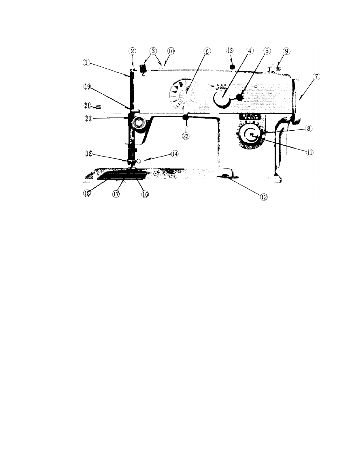
Fig. 1
Page 4

FEATURES AND PARTS
(Front View
0Take up Lever
(J) Pressure Release (Darning)
(3) Arm Thread Guides
(4) Zigzag Stitch Width Control
(D Needle Position Control
CD Pattern Selector Dial
0Hand Wheel
(D Stitch Length Control
(D Bobbin Winder
(i$ Bobbin Winder Tension
(Q)Push Button Reverse
(i^Drop Feed Control
(Q) Reverse Stitch Adjustment Lever
(R) Needle Clamp Screw
©Needle Plate
©Cover Plate
©Presser Foot
©Attachment and Foot Thumb Screw
©Thread Guide
© Tension
(g)Sew Lite Switch
©Stretch Lever
Page 5
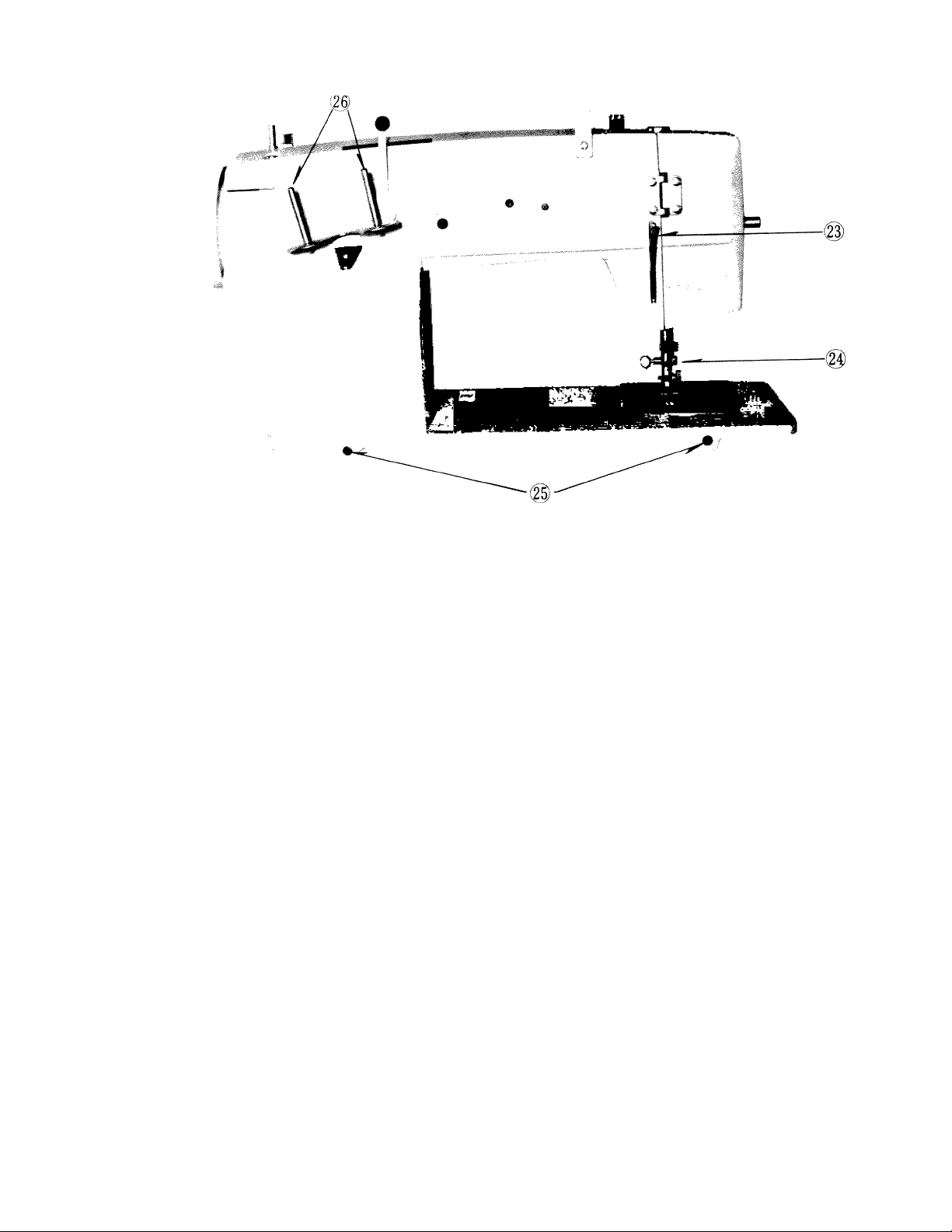
Fig. 2
i Presser Bar Lifter
) Thread Cutter
¡Head Hinge Mounting Holes
) Spool Pins
Page 6

NEEDLE-THREAD-FABRIC-STITCHINO cuide
Needle Cotton Meteenzed S^lk^ot
Fabric No Per inch
Extremely heavy «tr. r 10*° Heavy Duty
tarpaulin, sacking, ^ 6 to o 30
canvas, duck, etc.
Heavy upholstery fabric, 3(18) 8 to 10 Heavy Duty
ticking, denim, leatherette
Medium heavy drapery „ 10 to 12 Heavy Duty
fabric, velveteen, suiting, 2(16) j lOtoidi gQ
felt, terry, etc. ;
Medium broadcloth, ; 60 to „ „ a
percale, gingham, linen, 1 (14) 12 to 14 oq
chintz, taffeta, sheer wool, ;
shantung, etc.
Sheer voile, lawn, dimity, i fLil 50 A
crepe, handkerchief linen, 0(11) iFlaatic f^) .,00
plastic film, etc. |
Very sheer chiffon, | 100 to
batiste, lace, organdy, 00 1 e to 20 150 °0 «
ninon, net, marquisette, ; =
etc.
_____________
..............
..j ....
L_
l .
.......
.....j
..............
.......
---------------------------------— ~
............................
i j
Btoiu ,
.................................................-
Page 7

Fig. 3
p\
Page 8
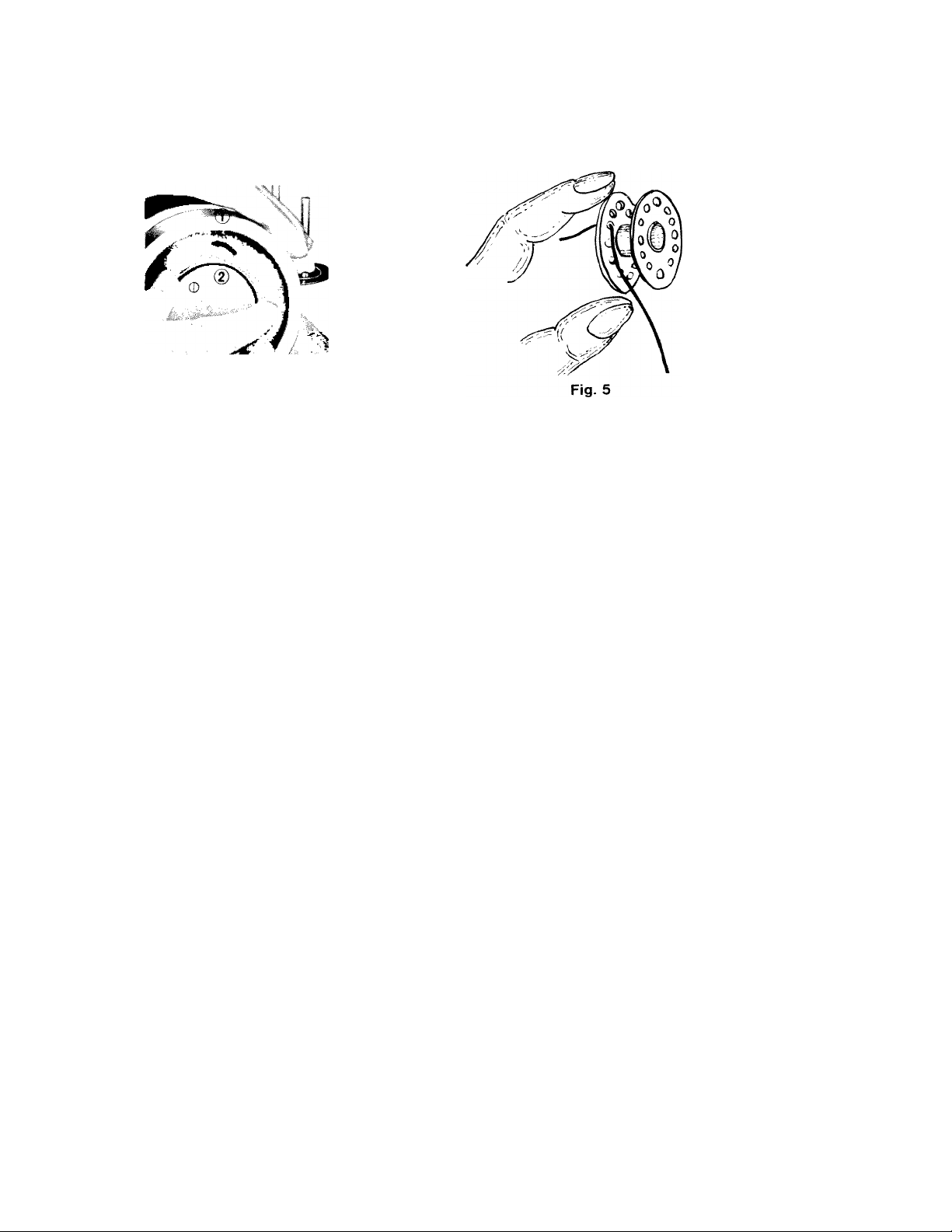
WINDING THE BOBBIN
Fig. 4
Disengage the hand wheel (1, Fig. 4) from the stitching mechanism by turning the
clutch (2, Fig. 4) toward you or counter clockwise. Place a spool of thread on one of
the spool pins and lead thread through the arm thread guide (3, Fig. 3). Run end of
thread through a hole in the bobbin edge and place bobbin on spindle of bobbin winder
(4, Fig. 3) fitting the notch on bobbin over small pin on spindle. Push bobbin winder
(5, Fig. 3) to the right, and hold thread end loosely then start machine slowly.
Bobbin will stop winding when it is filled. Turn clutch away frcMTi you until sewing
mechanism is again engaged so that needle moves when you turn the hand wheel.
Break off loose thread end used to start the winding.
Page 9
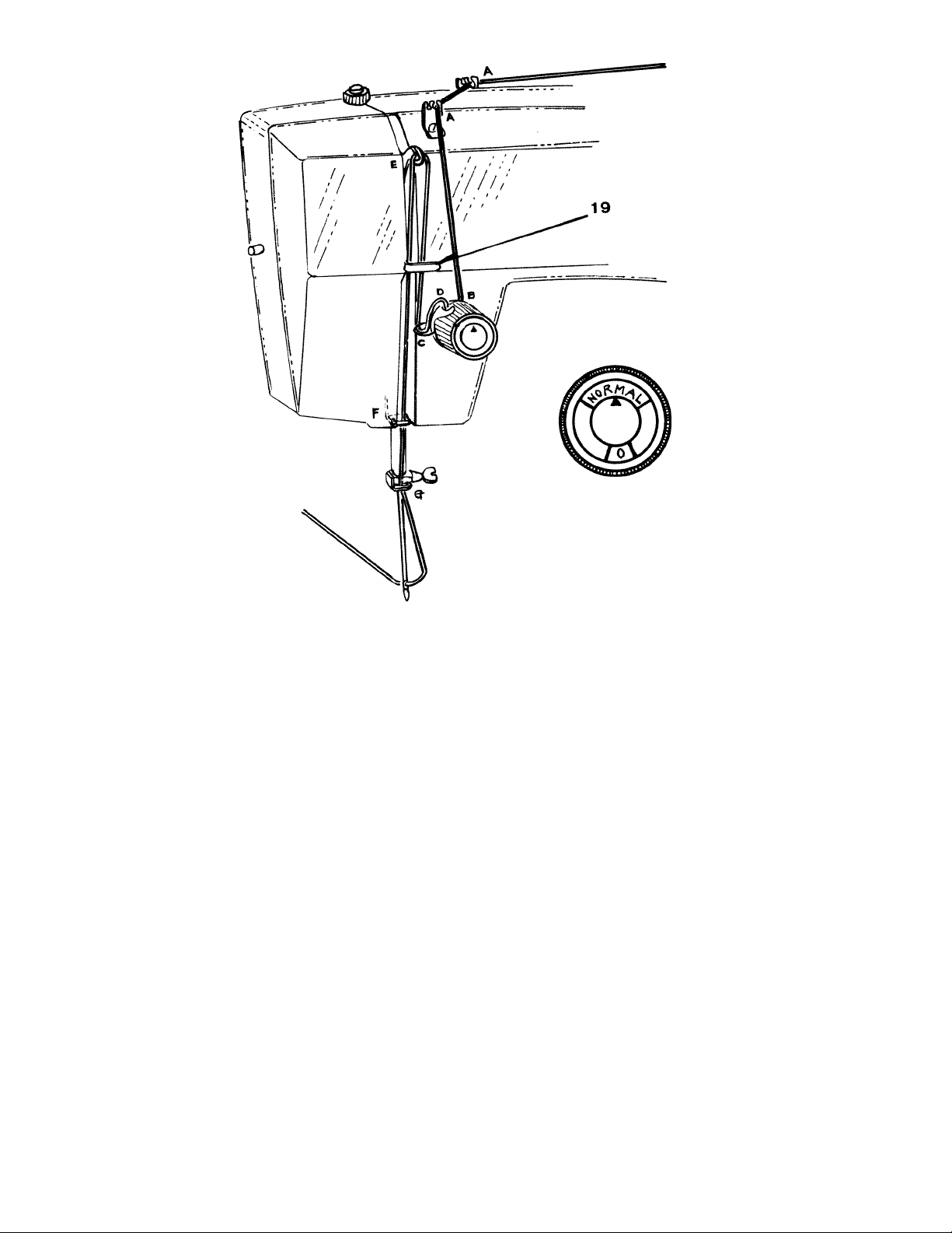
Fig. 6
Page 10
yppER THREADING
1. Turn the hand wheel toward you to raise the
take-up lever to its highest position.
2. Place a spool of thread on the spool pin.
3. Lead the thread through the upper arm thread
guides.
4. Down and between tension discs from right to
Left.
5. Draw the thread up through the check spring
and with a slight tug into the hook, See insert,
Fig. 6 )
6
. Then up through the eye of the take-up lever
from right to left.
7. Lead thread down, through the thread guide 19
and face plate guides then through the needle
bar guide.
8 Thread needle FROM front to back, drawing it
through about 3 or 4 inches. Hold the end of
the upper thread loosely and turn the hand wheel
toward you until the needle goes all the way
down and comes back up. A loop <Fig. 7 ) will
be formed over the upper thread which then
can be pulled out straight. Place both thread
ends under the presser foot and draw toward
the back of the machine, leaving both threads
three or four inches long.
Fig. 7
Page 11
10
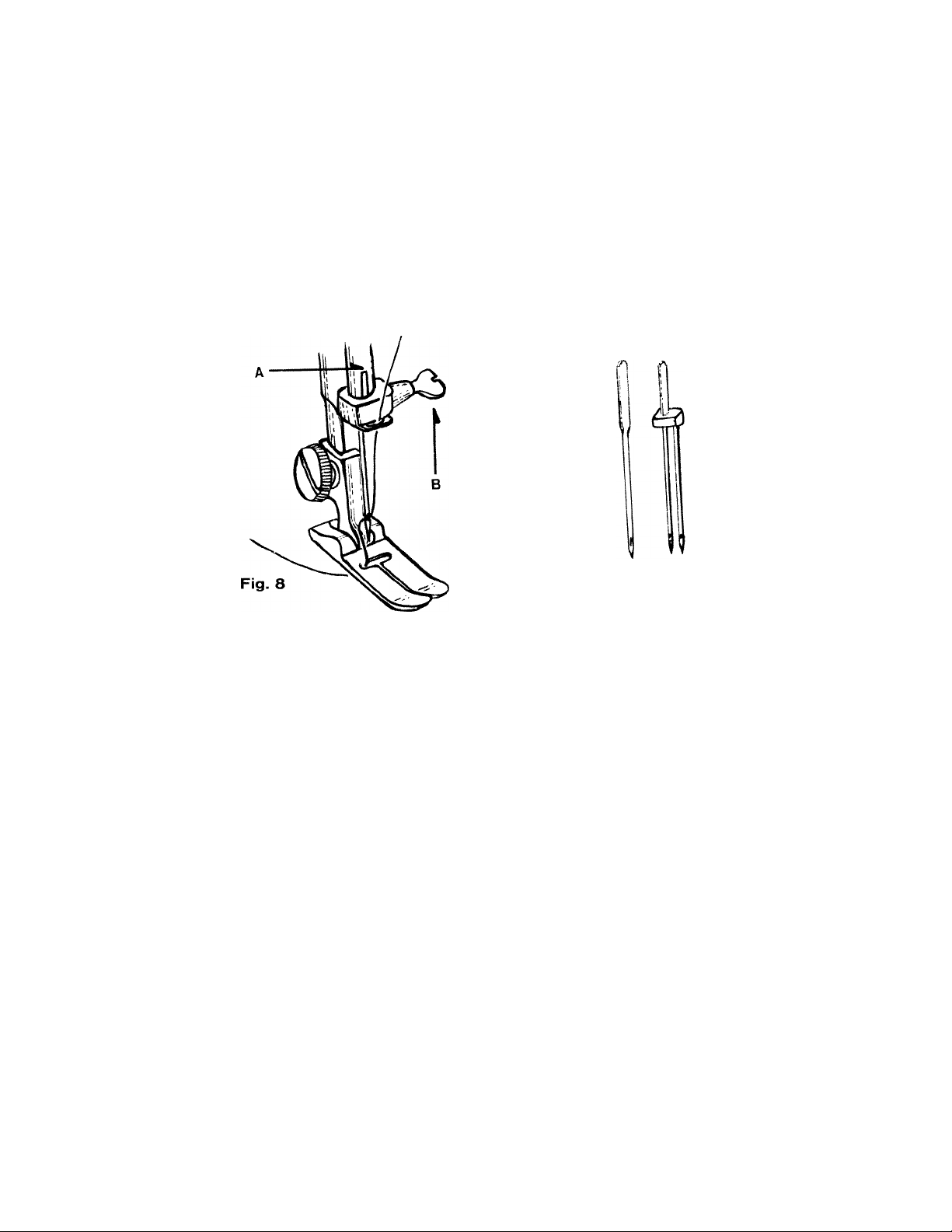
SETTING THE NEEDLE
See Fig. 8. Raise the needle bar (A) to its highest point, by turning hand wheel to»ard
you by hand. Loosen needle clamp screw B) and then needle can be removed or re
placed. When replacing needie (Flat Side to BACK, in needle clamp push ,t upward as
Lr as it will go into needle clamp hole. Tighten the Needle clamp screw (B) securely
with a screw driver.
a„„ Changing tn. n..di., m.». =n. compi...
by hand to be sure the neeaie is
rcvCution
Is in the correct position,
o. .»a hand wheat
Fig. 8-A
Page 12
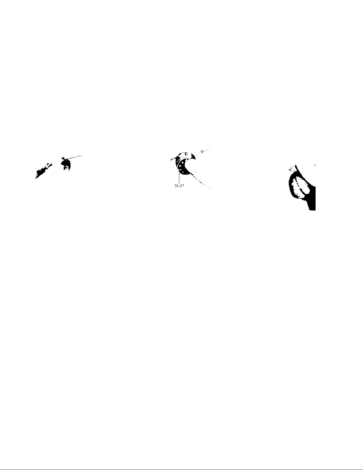
THREADING THE BOBBIN CASE
Step 1 (illustrated in Fig. 9 . Hold bobbin case between thumb and forefinger of left
hand, so that the slot in the edge of the bobbin case is on top, take the bobbin between
thumb and forefinger of right hand so that the thread on top leads from left to right.
Step 2 Insert bobbin into bobbin case, pull the thread into the slot of the bobbin case
as shown in Fig. 10, and draw it under the tension spring and into the fork-shaped open
ing of the spring as shown in Fig. 11.
11
Fig. 9
SLOT
T-,
m
Fig. 10
TENSION SPRiG
Fig. 11
Page 13

) i
BOBBIN: CASE
,-ig. 12
Raise needle bar to highest position, and lift hinged
cover plate. (See 1 6 Fig. 1 ) Hold the bobbin case
latch (D, rig. 12), between the thumb and forefinger
of the left hand, with at least three inches of thread
running from the top of the bobbin case to the right.
Insert and center the bobbin case on the stud of the
shuttle body, (C). Be sure the bobbin case finger lE)
is opposite the shuttle race notch, (A). Press the
bobbin case (B) into the shuttle as far as possible
until latch catches on the center post of the shuttle.
Then release the bobbin case latch, (D). Press bob
bin case again after latch has been released to make
sure the bobbin case is locked securely.
Close the cover plate.
Page 14
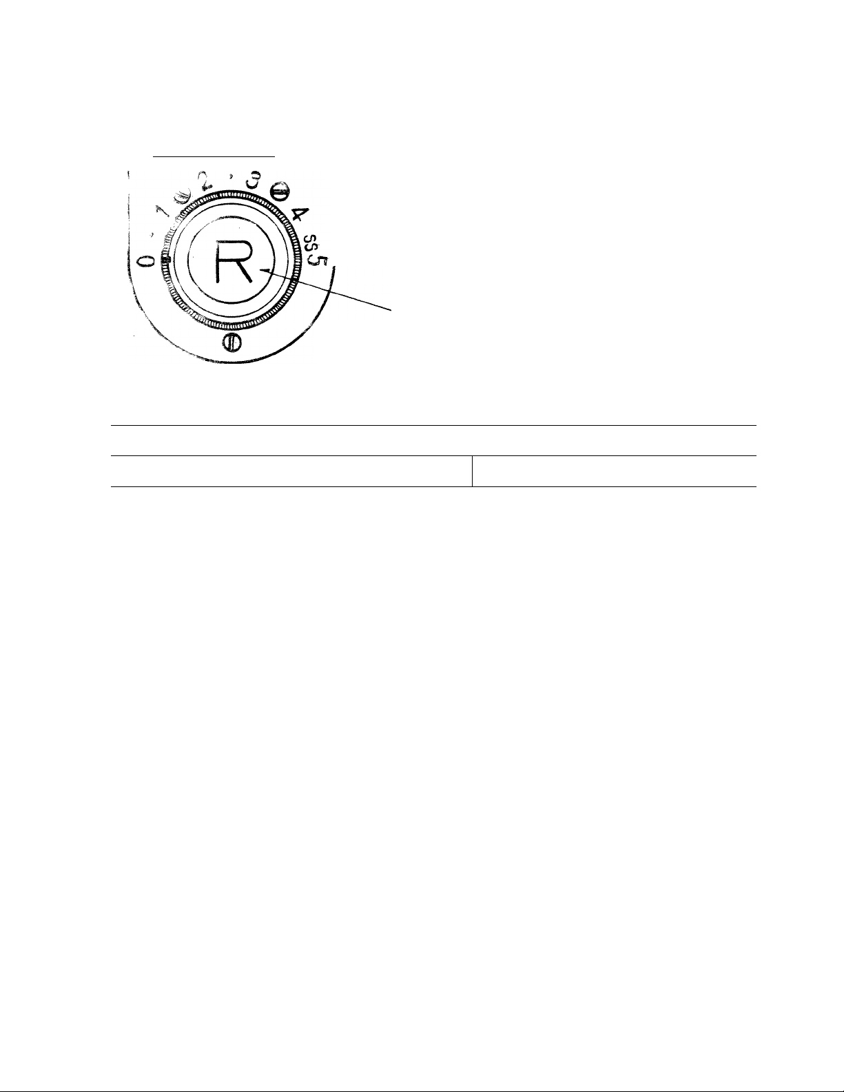
SETTING THE STITCH LENGTH
1 3
I
w 1 It —.11
1 LE N Q- TH J
Fig. 1 3-A
STITCH LENGTH CHART (Approximate)
•'-'inros indicator
Mumbsf of stitches per inch 1 No Feeding
length of Iho stiich is r-s-guiatsd by 'tha dial shown
in Fig. 13-A. Near O is the shortest stitch and 5 is
the longest, but the control may be set at any spot
between the markings for a variety of lengths. Turn
the dial to the right to lengthen and to the left to
shorten the stitch. The number stitch length you
choose appears over the indicator.
! 0
i
1 2
30 25 15
3 4
5
8
6
Page 15
S£.WmG
■'i: ,T, / r: to sew backward to tie the threads at the beginning or end of a seam,
press in the button ' A, Fig. 1 3A i as far as it will go. The machine will sew backward
as long as the button is held in.
IN REVERSE
ADJUSTING THE TENSIONS
Always adjust the upper tension with the presser foot down, as the tension is released
when it is raised. To increase the tension on the upper thread, turn dial ( Fig. 13 ) to the
right. To decrease, turn to the left.
Before adjusting lower tension be sure that the ma
chine is threaded properly. When necessary to change
the bobbin tension, turn small screw (Fig. 14) on side
of the bobbin case clockwise to tighten, counter
clockwise to loosen.
When the upper tensions are properly balanced, a
p>arfaot stitch will be formed with both threads interiocking in fabric (Fig. 15).
When the upper tension is too tight, the lower thread
is pulled up over the upper thread which is lying flat
on the fabric (Fig. 16). When the upper tension is
too loose, the upper thread forms loops over the
lower thread lying flat on the fabric (Fig. 17).
Fig. 1 3
Page 16

Fig. 15
\
Fig, 14
ADJUSTlNf^ PRESSURE AND FEEDING OF FABRIC
General Sewing. Usually for normal sewing the pressure bar cap or
j-im3f rolaasa, (U, Fig. 18) Is at its lowest position and the drop
f-eed knob is turned to "High” position, Fig, 1 9.
..
iiTif] Of Light Weight Fabrics. When lighter pressure is re
quired to sew-satisfactorily on thin silk or flimsy material, the pres
sure cap should be about halfway down. Release all the way by
pressing the snap lock, (A, Fig. 20), and then press cap (B) down
again to halfway spot. Lower the feed slightly by turning the black
dot on the knob to "Low” position.
Fig. 17
1 5
Fig. 19
Page 17

: ^ V ■ V;«Tiding, in order to move the fabric freely in any di-
raciioii iu7 mending, «-elease che pressure cap a com
pletely by pressing down on the snap lock, (A, Fig. 20).
V,,rr, ‘ha :'nob to "OOWM” position, which drops the feed well
belov/ the needle plate. To return feed to normal, return knob to
"HIGH”
!G TO SE1
Have take-up lever at highest point before starting to sew. Do not ^
try to help the feeding by pulling the material as this may deflect
the needle and cause it to break. p-ig_ 20
never run machine without material under the presser foot.
Place material and threads in position under the presser foot and
inw»r ‘he oresssr foot.
, :., ,d -«tee! loward you until thu needle is ut te higltest point, .'ou are no w
ruadv to uPSin sowing. By tiavlng the needle at its highest point, it is not neoessaty to
touoh the hand wheel to star, the machine. You merely press the control. The speed o,
the machine is regulated by increasing or deoreasig the amount o( pressure exerted on
con
Page 18
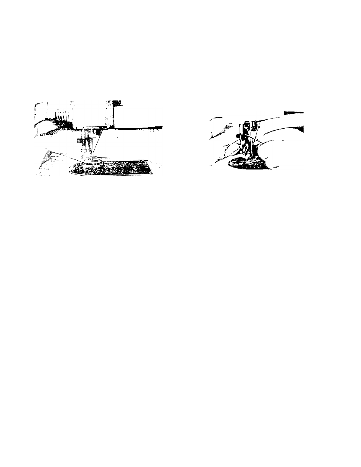
ft^MOVING THE WORK
, urs ‘O 7+00 the machine when the thread take-up lever and needle bar are at the
highest position. Now raise the presser foot and draw the fabric back and to the left,
rig 21-A and B, r.i.u pass the threads over the thread cutter. Pull down slightly, holding
thread in both hands, so as not to bend the needle. Leave the ends of thread under the
presser foot.
I
1 7
fig. 21 -A
Fig. 21-B
Page 19

o
.STR A i nWT STITCHING
For straight sewing on fine fabric
or ¥ery soft material, it is'advis-
’Oij :o :jj,j :l: s siraight stitchpess-
o
er foot and tne straight stitch nee
dle plato '-'/hich Of? included in your
accessory box. Both have narrow
needle slots.
MS
FOLLOWS
(1 ) Presser Foot
U) Loosen thumb screw (18, Fig. 1 ) and remove zigzag presser foot.
Replace with straight stitch presser foot (Fig. 23).
12) Needle Plate
(A) Slide cover plate (16, Fig. 1 ) lo the front as far as possible. '
dern-ove screws holding needle plats (is, Fig. 1 ) to bed plate
Fig. 22
Fig. 23
[C> damove zigzag needle plats,
\D) Replace with straight stitch needle plate (Fig. 22-B)
Of the needle will bmak in ¡trikinq tha foot or oíate
Grasp^outer nm of zigzag dial A, Fig. 23, and press down on lock's. ' ’ '
jurn dial .as rar to the left as possible. Pointer will then be on the zero mark
Page 20

Whe-! ! j • - siraight stitch needle plate and foot, be sure to make the following
-i-kiaa b'lfore starting to sew or the needle- break in striking the foot or needle
plii C ii-.
Set Your Machine as Follows
:■ :■ : .in control "A”' Fig. 24 at C
(center). ■
(2) Decorative stitch dial "B” for straight ‘
stitching.
i3) Zigzag width control "C” at "O”.
f ■) Strotoh stitch -;nntrol "D” at "'M”,
(5) Stitch length control "E” at suit material
being sewn.
See page 10 for stitches per inch.
19
Fig. 24
Page 21

SCTTWS' NEEDLE POSITION
I ne needle bar should be at its highest point when adjusting needle position to avoid
tearing the fabric or bending the needle.
"H” indicaies the right hand position - "C” center and
"L” left.
The C position is where most of your work will be
done.
Straight stitching.
Stretch stitching.
Designs.
H undreds of other uses.
The left and right hand position can be used for :
Straight stitch (cording and so forth )
Oecorative designs.
Hundreds of other uses.
The left hand position is best for sewing on buttons.
'-''-I,; position by control, 5 Fig. 25-A.
TN
TN
C R
L C
Page 22

lEOLES-UPPER THREAOIM'G AfiD SEWING
■l Be sure zigzag needle plate and presser foot are in place.
2 Set needle position control 5 Fig.-25B at twin needle position. Tnis will set a stop
to prevent the zigzag width control moving beyond the number 3 position.
;j.. ,-o,,uv/ oj,'d..ioi/)g instructions for single needle with these exceptions;
a. place, two spools of thread, matching or contrasting in color, one on each spool
pin. ’
b. Lead both threads through arm thread guides.
c. Bring threads down and around tension discs with one thread passing between the
back discs and the other between the front discs.
:/dai both threads as one until you reach the needle eye.
"'/w :r;.> b'r-.'id through each needle eye(Fig. 26).
4. Tha rnaxirnurn zigzag stitch width that can be sewn when using twin
needle is at the number 3 setting of the zigzag width control.
Any position above the number 3 position will break the twin needle.
5. Straight stitching and decorative stitch designs can be produced
in the same manner as for single needle sewing except for the
maximum zigzag width.
Page 23

SAMPLES OF CREATIVE EMBROIDERY (Fig.
3 9V/ 9 fgw stitches at 5 width than allow knob to spring back to O for a short
-jcjc. if necessary, to establish a rhythm.
"B" Set zigzag width control at the second line then move the control slowly back and
zb
juaaudii the Stop and Mumber 5.
"C” Set zigzag width at the first line. Gradually move the control from the Stop to 5
uiiowijig i( io snap back quickly.
"D” Set zigzag width at 5, stitch length at 2. Sew a few zigzag stitches. Drop feed (F,
;jf 3 or 4- stitches then raise it again. By operating the drop feed knob
rhythmically it is not necessary to count stitches.
By changing the needle position and varying the movement of the controls, hun
dreds of designs can be produced.
"E” Set drop feed knob at Down position and lock zigzag width control at the number
5 oosition. Take 3 or 4 stitches, leave needle in fabric and pivot fabric on needle
;o .naiic fidXi daisy petal. Continue until flower design is completed. Lock threads
by astting stllch width at O and sewing 3 or 4 stitches in center of design.
Page 24

iS-ATjye Hâ^BROIDERY
,,JT« tisaag pT-esser foot and xigxag. noodio plate^ aro In placa.
23
I Set decorative stitch control (B, Fig. 24 )at “M"
position.
.. "ji needle position control at “L” position.
nfmitfi 111 r'n
Fig. 27
3. With the zigzag width control (C, Fig. 24) set at the Number 5 and stitch length
control i ,-" j, '-A) as near O as- possible without stopping the feeding action, a satin
stitch is produced (Fig. 27 )
4. With the machine set for a short stitch length, different designs can be made by
turning the zigzag width control back and forth between 0 apd 5 or any other
combinations of widths. Try setting the zigzag width control at (C, Fig. 24) the
first iina and the various other iines.
mia mum mìm iüü mmu umu 111^
A
Set a rhythm for yourself and then proceed.
Jïïiîll L.1Î rm Ufn«ru_,' mm'.„.TrfïïLiin^^
After awhile you will become quite skillful, vary
ing your designs by the speed of the machine,
stitch length and manipulation of the zigzag
width control.
D mmNwmmAmmmmm
Fig. 28
Page 25

EMBROIDERING WITH A HOOP
it 13^ easy to follow a stamped design or to
wui A ras land when embroidering or mono-
gramfuing. (See Fig. 29) Release the prassurs
from the foot by pressing down the snap lock
on the darner. Turn the drop feed knob to
"DN” position (See Fig. 29).
oireicn ine fabric in an embroidery hoop, and
place under the needle after removing the
prnssar foot. Set the stitch width at the size
you prefer and lower the presser bar lifter.
Then operate the machine at a rather high
speed while moving the hoop slowly with
both hands. Work carefully and be sure to keep fingers out of the path of the needle
Should you encounter skip stitches the fabric is not stretched tight enough or a darning
spring is needed (see attachments avaiiabte from yourdeaJer illustrated in the back of
this book).
Page 26

gyTTOM WOLES
yarious widths and lengths can be made automatically by
turning the dial Fig. 24),
i 51 the correct length buttonhole required add Jainch
to the cutting 3o;vr> for bar tacks.
To obtain the length of the cutting-space, the opening through
' the button passes, is measured by adding the width (A)
nn!
irtjcxness (3) of the button (Fig. 32,
width of the buttonhole sides are governed by the material
ysed. Set zig.zag stitch width control on number 5 for thick
materia! and a lower number for thin material,.
I\^ark the beginning and end of the buttonhole on fabric with a
basting line or tailor’s chalk. Make one on scrap fabric
foliowing diroctions 'below to be sure jtrachine adjustments- are
corrrect.
^. Replace pfasser foot with special purpose buttonhole foot.
This provides maximum visibility and allows closely spaced
stitches to feed evenly (Fig. 31 ).
2. Set needle in left position
3. Set zigzag stitch width control (C, Fig. 24) to suit material
being sewn or width of buttonhole desired (number 5 for the
widest buttonhole). .
4. Set stitch length control (E, Fig. 24) as close to 0 as possible
without stopping the feeding action.
5. Set stretch stitch control at manual position.
25
Fig. 30
Page 27

; ] !' dacorative stitch dial (A, Fig. 34) to sew the left
i). Lowar needle carafully Into mark on
fabric indicating the end of the buttonhole. Lower
presser foot and sew entire length of buttonhole
: (- orvvara feeding).
7’. With needle out of the cloth, set decorative stitch
dial for bar tack (Step 2). Sew 4 or 5 stitches.
3. With iveeclie out of cloth, set decorative stitch dial
to sew right side of the buttonhole (Step 3). This
_ will reverse the feeding motion.
9. With needle out of the cloth, set decorative stitch
dial for bar tack (Step 4). Sew 4 or 5 stitches.
10. !f the stitch density on the buttonhole sides are
different adjust by moving lever ("B” Fig. 34) to
either the right ( —) or left ( w).
To increase the stitch density on the right hand side
nr inn buitonhole move lever to the right ( —).
To increase the feeding move "B” to the left ( +).
PL'BASn MOTE!
if yo'i ;)l3№ io make butionhol®» ori sheer or soft
u'j.at-Gvl'll, place tarlatan or paper under fabric which
carr be torn away after stitching.
5
II
s||
T||
P § ;P:
/
3
p > >
'ij
Page 28

SEWING ON BUTTONS
, He., u va presser foot and replace with special purpose button sewing
foot iFig. 36 ) ,
y.,, , '-‘DN” position ¡'.Fig- 35).
3 Set zigzag width control at "0” ^ i «vi"
, Set needle position control at “L” and decorative stitch dial a. .Vi
Place the button so that its left hole comes directly under the presser
the zigzag width control to produce a zigzag stitch until the
"" needle enters the right hand hole of the button. Turn the balance
wheel slowly by hand to be sure the needle clears both holes in the
button. Correct width if necessary.
g When needle goes into the center of each hole, run the macfiins at
* a medium speed, making five or six stitches, stopping with the needle
in the left hole.
7. To lock the zigzag stitch and prevent ravelling,
set the zigzag stitch width control to 0 (remem
bering its original setting i and take a few stitches
in the same hole. If you wish, you may place a
rounded toothpick over the button between the
two holes, and sew button to fabric in the regular
way. Remove the tooth-nick end wind th-read under
button forming a shank to fasten.
27
Fig. 36
Page 29

’ a t't^Bfns
STRETCH
i
Needle
Position Length Width
Stitch
STITCH
Zigzag
Stretch
Patterns
Needle Stitch Zigzag
Position
Length Width
Wh.„ «„¡„g „ ,h. stitching, be sure to set the stretch
lover (22, Fig. 1 ) h -ss- position with red indicetor on top cover.
Page 30

MULTIPLE ZIGZAG STITCH
aaaaaaaaaaa
/\/\/\/\/\/\/\/\/\/\/\
/vvvvvvvvvv\
i-ig. 40
ft,.
Use zigzag
g. Set stitch length control to suit-Number 5 for the widest width.
C.
Set
decorative stitch dial at multiple zigzag stitch,
p. Set zigzag width control at Number 5 for widest stitch.
needle plate and presser foot.
pig^ 41 material
USE:
When replacing worn blanket bindings for both a
decorative and durable finish. Fig. 41.
When overcasting an edge to prevent
When applying elastic waist bands to
dresses be sure to stretch the
applied to insure ful I ness required in the
When sewing
it
will prevant puckering.
a
zigzag stitch on
elastic
soft
fraying.
skirts
as it
garment.
or sheer
29
and
is
There are hundreds of other uses which will become apparent as you use the machine.
Page 31

-о Г1ТСН HEM-
JO о jCdiiuci/'j ¿¡gzag root 'Fig. 42).
Set stitch length control at number 3 or 4.
'■'estls jcsition control at “Center” position.
Zigzag stitch width to suit material being sewn.
The lower the number, the smaller the sidewise stitch,
olinu Stitch hems provide a durable hern finish that is
almost invisible and comparable to hand sewing.
ep-nr j che garment in the same manner as for hand
hemming.
Fig. 42
Ttap
Stao
St ep
1 '
iy. 40). If hern with folded edge is used make first fold “x" deep.
Turr! hem to the depth desired and baste -\T' from ’ippor edge. Press m oiaco.
Fold hem oacii msward right side o) jof.j'Oiit iaaviny m" excandeu.
Plnca material under presser foot, sew with stitch length set to suit material
being sewn and make a side wise stitch about every ^4" of an inch of sewing.
Page 32

MANUAL OPERATION
i; , 'igiag prasser foot and zigzag needle
plate are in place and machine is set for manual oper
ation. Use for;
j / •: •. :*T1NG HOGHS
¿ijgzag suicn diong the worn edges, catching the fabric
as the needle swings to the left, and allowing the needle
‘o ‘list m«-'! 'v-f.-sf »he edge of the fabric on the right
V j ~
FJ^TCHimCS
(Machine bastes patch into place by placing fabric under
hole or worn area which has been cut away. Then
zigzag stitch the patch into place by overcasting around
edge of hole.
APPljro 1 -r
F?q. cbaign to fabric and zigzag stitch follow-
:,Kj shape of the design outlining it entirely and
remove excess material on the outer edge by trimming
it away after stitching.
Fig. 46-Baste design to fabric and overcast a zigzag
stitch around the design outlining it entirely.
Hundred of others uses will become apparent as you
continue to use the machine. Try the mulitple zigzag
stitch for these operations. Also, for best-result set
speed control slower when sewing around contours and
faster for straight lines.
31
%
Fig. 44
Fig. 46
Page 33

HOW TO USE ACCESSORIES'
. With needle^ at its highest position
r3p-lac8 r-sgufar presser foot with narrow- hemmer (Fig.
47) b«inq sure to tighten it securaly in place. Set
paiieni selector dial at manual position, needle pos
itioning control center, zigzag stitch width control at
off io,‘ oiraj-ghi stitched hem or at number 3 for zigzag
stitched hem. Set stitch length control to suit.
For a plain narrow, hem make a % inch double fold for
about two inches along edge of fabric. Hold each end
of the two inch fold and slip underneath hemmer. Bring
fold up into the scroll of HEMMER, draw fabric forward
to end and fasten with needle point. Lower presser
bar lifter. Gently pull end of thread as you start stitching
(Fig, 48 for straight stitched hem Fig. 49 for zigzag
stitct««i hem).
Guide material slightly to left and it will take a double
turn through scroll.
The narrow heir! provides an excellsni finish *or edges
of niff!-') ■ or any other dainty work .
Fig. 49
;
Page 34

ujiCE TRl'MMEO HEM
'o sew a narrow hem and attach lace in one stitching,
as above, guiding
’ic:
i_j4CE SD<'w
Hold i n; ; (r :n ^
fabric, insert both in scroll as for plain narrow hem (Fig.
52): ioc .¡5;-iT ,'oil ало sew'^ in lacs. When the stitching
IS completed, the hem is pressed to the wrong side.
FRENCH SmAM
place material with right sides facing each other and the
piece of material )4> inch from right hand edge of lower
piece. Insert in hemmer scroll a llowing hem to roll over and
jow ;it top fabric making гг зпо п ssam. Por coraing effect,
use zigzag stitch ',vide enough to catch both edges of the
lay be used in the same way.
' ■ next to needle (rig. 5i), Sew hem
iacs under needle and hem into scroll.
'"'МТЧ INVISIBLE STITCHIMO
n rj,Ti raw edge on right hand side of
_____
narrov/ rolled hem and sew with satin stitch. This can
be used for j:overing chairs and so forth (Fig. 53).
HEMMING ACROSS A SEAM
To hem across a seam, cut the seam
folds at an angle so they will lead
into the hemmer gradually. Press seam
open. Stitch across-the seam at the-ex-
ireme edge to hold it together and for
added firmness. It may be necessary
Fig. 50
to pull the material slightly when hem
ming over the seam (Fig. 50).
33
Fig, 51
Fig. 52
Fig. 53
Page 35

QuiLTiMa. '-литЕ
Page 36

35
Ti‘i
.Adjustable cording and zipper foot
■: ■ ' ■ to n'ake^ and insert
coversd Goraing and to sew in zippers.
yoG'iOi' A-'irnb '5Gr )w to slide foot to either
;jgG; ..;r w': Gjsdle.
COFiDING. Fo , ,,,io atrip of fabric over
cord. Loosen thumb screw and set foot so
neeaie is csritered in needle hole. Machine
bastes cord in plac8(Fig. 60) •
To sew covered cord to material, reset
. adjustable foot so needle stitches closer to
cord, and on edge of base fabric.
r ■
S1EWING m ZIPPER
Loosen thumb screw and slide foot so needle enters
center of needle hole. Guide metal of zipper along
edge of foot (Fig. 61). Stitching should be close to
zipper to allow easy opening and closing. Adjust to
sew from either right or left side, whichever is more
convenient.
Fig. 59
rig. 61
Page 37

;iLE CORDING AND ZIPPER FOOT
/; .
//'
i'V
///
hi
'!!
/,
.-ig. 62
rig. 60
r'r. 54
Page 38

CLEAMIG AND OILING THE SHUTTLE
(Se-e Figs. 6S and 66)
rha stitch fOfming mechanism occasionally becomes clogged with loose threads and
'in:. This will interfere with the efficient operation of the machine. Cleaning and
removal of the lint will safeguard the performance. To remove the shuttle assembly,
proceed as follows:
1. Turn ‘he balance wheel until the needle reaches its highest position. Tilt head
back on its hinges.
2. Remove bobbin case (A), Fig. 65.
3. Turn the two shuttle race cover clamps (B) outward and remove the shuttle
race cover (C) and shuttle body (D).
37
Fig. 65
Fig. 66
Page 39

33
■A, Ctean Che shuttle race, the shuttle and shuttle race cover by removing all threads,
5. Apply a drop of oil with finger tip to outer edge of shuttle
When the cleaning has been compieted, proceed as follows to replace the shuttle
doo8inoiy :
1. Turn ihs balance wheel until the needle reaches its highest position
*• (D), against shuttle driver and adjust into posit,on
3. déplacé shuttle race cover. (C), fitting pm a, lower edge into notch, 'and lock
into posit.on with shuttle race cover clamps. (Bj, making certain the clamps
, ) üaen snapped securely into position.
’'!C C)obbin into bobbin case.
CARE AND MAINTENANCE OF YOUR MACHINE
HOW TO OIL YOUR IWACHINE
Your macnine should be oiled occasionally to
keep it operating smoothly, how often depends
on ctie amount of sewing you do.
Before oiling the upper pari of the sewing unit
at points indicated by arrows in (Fig. 67) 'I'lrn
nand wheel coward you undi che caxo-up Sever
.-3 at ICO ,O',vast point.
Fig, 67
Page 40

•lachanism under bed of machine, tip the head back on its hinges and oil all
oartj i.naic£i:acj by arrows Figuras 68 &. 69 and red spots on machine.
Fig. 69
HOmi TO REPLACE THE LIGHT BULB
39
Fig. 68
Open Face (Fig. 68). Unscrew bulb and insert new one.
For long life and correct size, be sure it is a genuine
White part.
•■oirbartflbfSK,"'
Page 41

s 11
ffi ife
iS)
1'^' I
-msm
^163
.
...
1 i
(n)
/n>
in
(fi)
;15;
CL) Plastic Oiler (sealed and filled).
Package of Needles (5 Straight).
Large Screw Driver.
CL Small Screw Oriver,
CP Sun'; )f Suida,
Up'..Seth >_Sjide,
'CZC’Button Sewing Foot. d) Buttonhole Foot.
©Presser Foot for Straight Sewing.
(pj) Narrow Hemmer.
'iQC'Twin Needles.
(jj) Thuma Screw.
©Felt Washers(2) (for spool pins).
© Bobbins (3),
(0)Needle Plate for Straight Sewing.
Page 42

TROUBLE CHART
41
aole Cause
If Machine ^ Thread or lint in
3inds ^ ^-acT'vay
Correction
1 —With take-up lever in highest position, tilt
head back on hinges and remove bobbin case.
lint gleaner
BOBBIN
CASE
BOBBIN
NOTCH
HOOK
RACE
' 2—Turn clamps outward and remove race cover.
: 3—Remove hook.
' 4—Clean thread and lint from all parts, includ-
■ i n g race.
: S—Run a drop of oil along rim of hook.
: 6—Replace shuttle, then race cover.
! Snap clamps into place.
7 —Grasp threaded bobbin case by latch and
' replace, fitting tongue into notch of race
: cover.
Page 43

'oubie
Probable Cause
Corrección
Skipping Sent need!«
Needle placed
incorrectly in clamp
Too fine a needle for ^ See needle and thread chart, page 5.
thread being used^_______________________________
Bobbin not wound Rewind bobbin.
evenly
Uneven
stitches
, Pulling or holding
material
Not enough tension
; on upper thread
i Poor quality thread
: Needle too fine for
1 thread being used
Discard and replace.
See instruction, page 10-
_
____
________
1 Avoid pulling or holding material
; Increase tension.
Try oiNorenl thr:v;jC,
; See needle and thread chart,
___________
, just
guide it.
page
5.
Page 44

43
Trouble Probable Cause
U poa r
thread
breaking
niproperly threaded Refer to threading instructions see page 8
__________________
Too much tension tension on upper thread bv iurnina
Starting wrth take up , Always staTF^sewing'^^'^mTlalce^^ ~
m .ncorrect position : highest position. ^
Bent or blunt needle
Material
puckeri nn
Tensions too tight ! See tensions adjustment, page 14.
bull needle
Stitch length too long i Pnduce stitch length.
Correction
and rethread machine.
thread tension knob to lower number.
Discard all blunt or bent needles and replace
^ with new.
I Change needle.
Page 45

44
!
Your sewing machine comes equipped with the basic set of acces-
; usscribed earlier in this book.
The foilowing pages illustrate additional time saving attachments
ci'iiu nava been designed specifically for your machine. They are
available at modest cost from your dealer. If your dealer cannot
suDpiY you with these items, ask him to order them for you by part
number. Then you will be assured of receiving the genuine part
designed for best performance with your machine.
If a sewing machine dealer is not available, mail your inquiry
directly to:
WHITE SEWING MACHINE COMPANY
11750 BERE.A RO.AD
CLEVELAND. OHIO 44 111
In Canada
WHITE CONSOLIDATED INDUSTRIES, LTD.
1470 BIRCHMOUNT ROAD
SCARBOROUGH, ONTARIO, CAN.ADA
Page 46

= AVAYLJ^BLB FOR YOUR
45
''■—^ /7^ -\ i 1 ' i f-f
£55.2.'__My
part !5U03
Pm if Ar
PART S: 82528
Afiachmenf Foot
Fig. 71
Hemmers
a-a
PART :;;4990
Darning Spring
part ¿74159
Sinder
3^
MACH1^3H
.4?
\
V .
PART =1873
lording &
ipper Foot
V
PART C 76554
Edgestitcher
part ^76553
part '76552 part 57 76551 PART =76550
■ r^ntrol must be in the left position when using these attachments.
Page 47

ts
ATTACHMENT FOOT
In order to attach the binder, sdgestitcher and the
hemmers, it is necessary to remove the presser foot
and replace it with the attachment foot ^ ^'9. ^ ,
Mount binder, edgestitcher or hemmers. slid ^9 the
attachment to the left as far as possible and tighten
The^mounting slot enables you to sew as close to
oras far away from the edge as desired. Just rnove
the attachment to the correct position before tight
ening the mounting screw.
Fig. 72
edgestitcher
The edgestitcher is used in
making dainty lace insertions,
edgings and pipings. ^
The slots in the edgesticher
serve as guides in sewing
together various pieces of
rnateriai. if you want to sew
lace, lace and embroidery, _
or lace and tucked strips
toaether, place the piece of _
mc^terial that will be on top m slot 1
Fo, insiance, if you =-/^^№*”03 ?n slot 4 (Fig. 73
place the fabric in slot 1
Fig. 73 _
(Fig. 74) and lower fabric in slot ^
' to a finished edge of fabric
(D
4.
Page 48

3a sure to draw the lace and materia! under the needle and back of the
that the feed will carry it backward as you stitch.
-n ; u ) ^ '.'m in the left hand and the lace in the right, being sure the
Rick Rack can be sewn to the edge of the material in the same manner.
To trirn >yith wide piping, place the fabric in slot 4, and the fold of the
uup;n;' :"r t in slot 3, for a narrow piping place fabric in slot 2 and
the . , . } ) , , ; of the piping to the right in slot 3,
Slot S may be used as a guide in stitching a French seam
See Fins, for sugges'tions
on how to use the edgestitcher.
There are hundreds of other uses.
j -.3 Xu’
47
Fig . 76
Fig, 77
Fig. 78
Page 49

rhi.3 iM.'.i<.'/•)t folds bias binding and applies it co the edge _of material
r m operation. Slots on scroll of the binder'are for corresponding widths
; -' ' 'olded bias binding. The open mouth of binder scroll is used
-or
unfoiaea otas strips cut 15/16 inch wide.
FO^LOEO BINDING (Fig. 81) _
Cut 3 ooint on folded binding, insert in appropriate
sjoc. Craw uirougn slot and under binder with strong -
pin. Test stitching to be sure it is on the edge. :
Adjust by sliding binder to right or left.
O o;*;,) MU' 'OiNDlNG (Fig. 81)
Two bindings can be sewn on fabric edge also in one
operation. When two are used, always skip one size
Kot A/aa-i \.vidths, inserting each in correct size slot.
Hj4iOIU-C4JT bias BINDING (Fig. 82)
Cut 1 5/1 6 inch bias binding fold in half for a couple
of inches. Cut binding (diagonally toward end, '
almost to fold). Slip fold into center of binder.
Draw back until cut opens and binding encircles
opens end of scroll. Test stitching to be sure
it is on the edge. Adjust if necessary.
See Fig. 79 and 80 for suggestions on how to
MSS the binder. There are hundreds of other uses.
Fig. 79
Fig. 81
Fig. 80
Fig. 82
Page 50

THE SET OF HEMMERS
Before attaching any of the hemmers, be sure
bobcrn thread hs pulled up. Then,, with hemmer in
place, hold top thread loosely and turn hand wheel
one full turn toward you, making a loop under
^‘‘ jP Dobbin tnread with both hands
and slip horizontally under hemmer toward back.
Bobbin thread will catch loop and carry .upper
thread to back of hemmer.
Foia material to suit tor two inches along eciu.a,
hold at each end of fold. Slip fold into guide and
up over spoon (Fig. 83). Fold hem in material back of hemmer.
Draw forward to end of hem and fasten with point of needle.
Pull on threads gently as you start stitching.
Fig, 83
SET
You can make a hem 1/4”, 3/8”, 5/8”, or 7/8 in width, depending upon
which hammer you use. For a few of the many uses see Figs. 84—89.
Page 51

■мг,ггя SET
Fig. 84 Fig. 85
Fig. 87
Fig. 86
Fig. 88
Page 52

MUFFLER
Fig. 90
The ruffler will produce yards of delicate ruffling or precision pleating.
.lu/fliiig can also be done and sewn to another piece of fabric at the same time.
This highly versatile attachment despite its wide range of use, is simple to use.
Use the ruffler for making aprons, curtains, pleating a skirt, adding fullness to
:ii =
..........
: } -o . iiress, etc.
51
F''-'
4
Page 53

RÜFFLER
Fig. 93
Fig, 94
Page 54

r
read these important instructions which were written to aid you in
placing your new sewing machins in its portable case.
rarnove the foot control which is fastened inside the base to avoid
damage in shipping. After unpacking the sewing machine unit, being
certain ‘o take out the instruction book, guarantee and accessory box,
lay the unit face down on a table. You will see two clamping screws A
entering head hinge holes B on the underside of the back.
On the base you will find two head hinges C which will fit into holes B.
Lower the base onto the sewing machine fitting hinges C into holes B.
Tinhtsn screws A securely with a screw driver.
.IMG SEWING HEAD IN PORTABLE CASE
To make
partition
“Motor” on the block attached to the outer section of the base.
Then insert the other cord into the “Light” receptacle.
Place th=> foot control on the floor, insert plug into a wall outlet (110-115
.;.us) and vou are
beco'rne familiar with the threading of ttie machine, tension adjustments and
all the other
the
electrical connection draw the two wires through the slot in the
of
the base. Plug the cord labeled “Motor” into the receptacle marked
ready to sew. But first read the instruction book to
features designed to make sewing a pleasure.
See Fig. 98 and 99
Page 55

legs-^ on
CABINETS
See Fig. 1 00
s. Place cabinet body upside down on
smooth level surface ( use^ packing
material as cushion to prevent
marking top, ’
0 Slip lea into position between corner
'■ b;!i:ks and down as far as it w.M go
with stud fitting into slot or hole m
metal bracket.
3 Add wing nut and tighten securely.
Fig. 99
Page 56

SEWING HEAD IN CABINET
^ -’■ nok off both head hinge set screws
= ^ hols is clear.
2 Tilt head hinga tongues up and back
as rai as tney will go.
3. Carefully slip head onto head hinges
. , maxiiiu sure tongues are inserted
as far as they can go into head
hinge holes.
4. Allow the head to rest in its tilted-
back position,
5. Tighta.n both set screws securely
with screw driver.
6. Plug electrical Isads into sockets
ioca iau inside cabinet. Cord identi
fied wi Ui "nnotor" tag must be plugged
into socket marked “motor”.
Un tagged cord goes to “light”
socket.
See Fig. 1 01
Page 57

CHANGliJG “V”
I
'•f
Fig. 1 02
Fig. 1 03
Foliowing are the instructions for adjusting and changing the “V” belt:
(1) Remove three screws holding rear cover(Fig.102) by tipping it out at the bottom
and pivoting around the hand wheel away from the front of the machine.
(2) To adjust “V” belt, loosen screws (A, Fig,103) and move bracket B up to loosen
bait and down to tighten. ~
(3) To 'em ova “V” belt:
iA) Fiamove top cover.
(B ) Loosen clutch (C, Fig.102)
______________
,
(C) Loosen screws “A” {Fig.1 03) and move bracket “B” to its highest position.
(O) Slip belt off motor pulley and then over hand wheel.
(E) Replace “V” belt by slipping it over hand wheel and then over motor
{F) Adjust as noted under No. 2.
®
 Loading...