

Page 1
INSTRUCTION MANUAL
MODEL 511-F SEWING MACHINE
Page 2
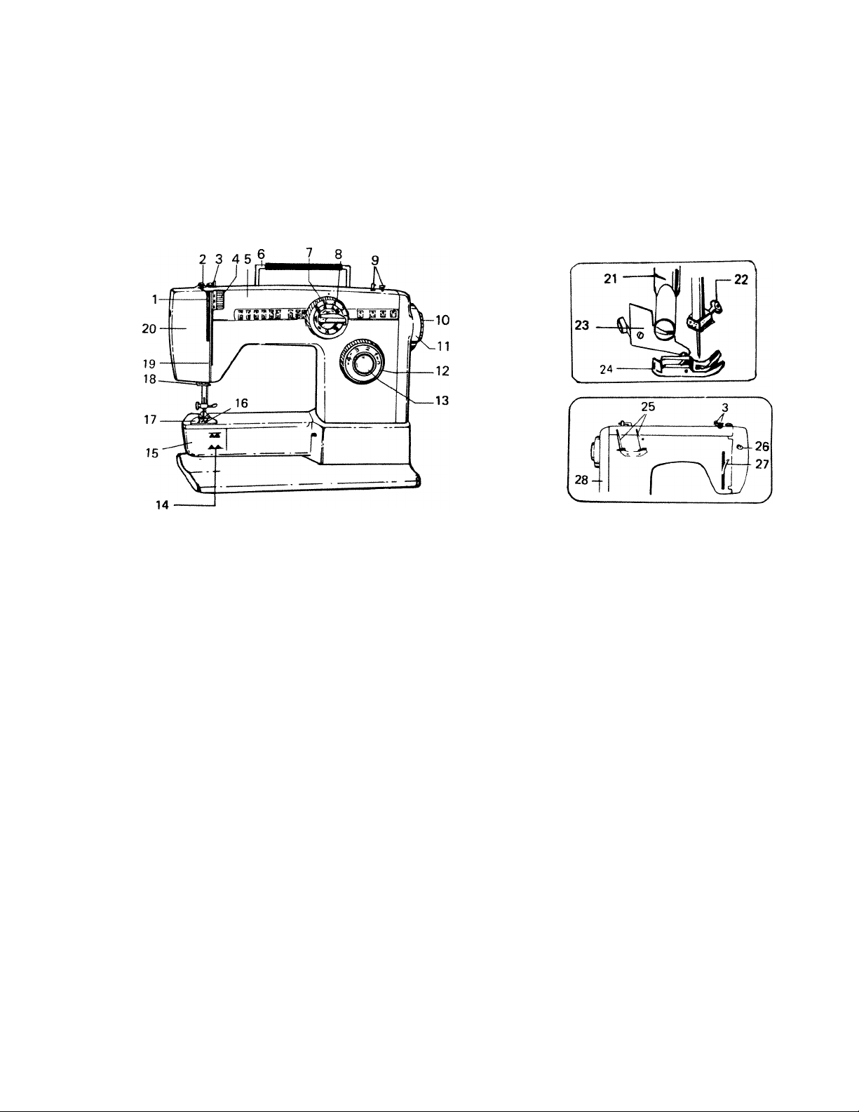
FEATURES AND PARTS
1. Thread Take-up Lever
2. Pressure Release (Darning)
3. Top Plate Thread Guide
4. Tension Regulator
5. Top Plate
6. Handle
7. Needle Position and
Pattern Selector Dial
8. Zigzag Width Control Dial
9. Bobbin Winder
10. Fly Wheel Clutch
11. Flywheel
12. Stitch Length Control Dial
13. Reverse Button
14. Drop Feed (under Shuttle Cover)
15. Shuttle Race Cover
16. Feed Dog
17. Needle Plate
18. Thread Guide
19. Thread Guide
20. Face Plate
21. Thread Cutter
22. Needle Clamp
23. Presser Foot Thumb Screw
24. Presser Foot
25. Spool Pins
26. Light Switch
27. Presser Bar Lifter
28. Motor and Belt Cover
Page 3
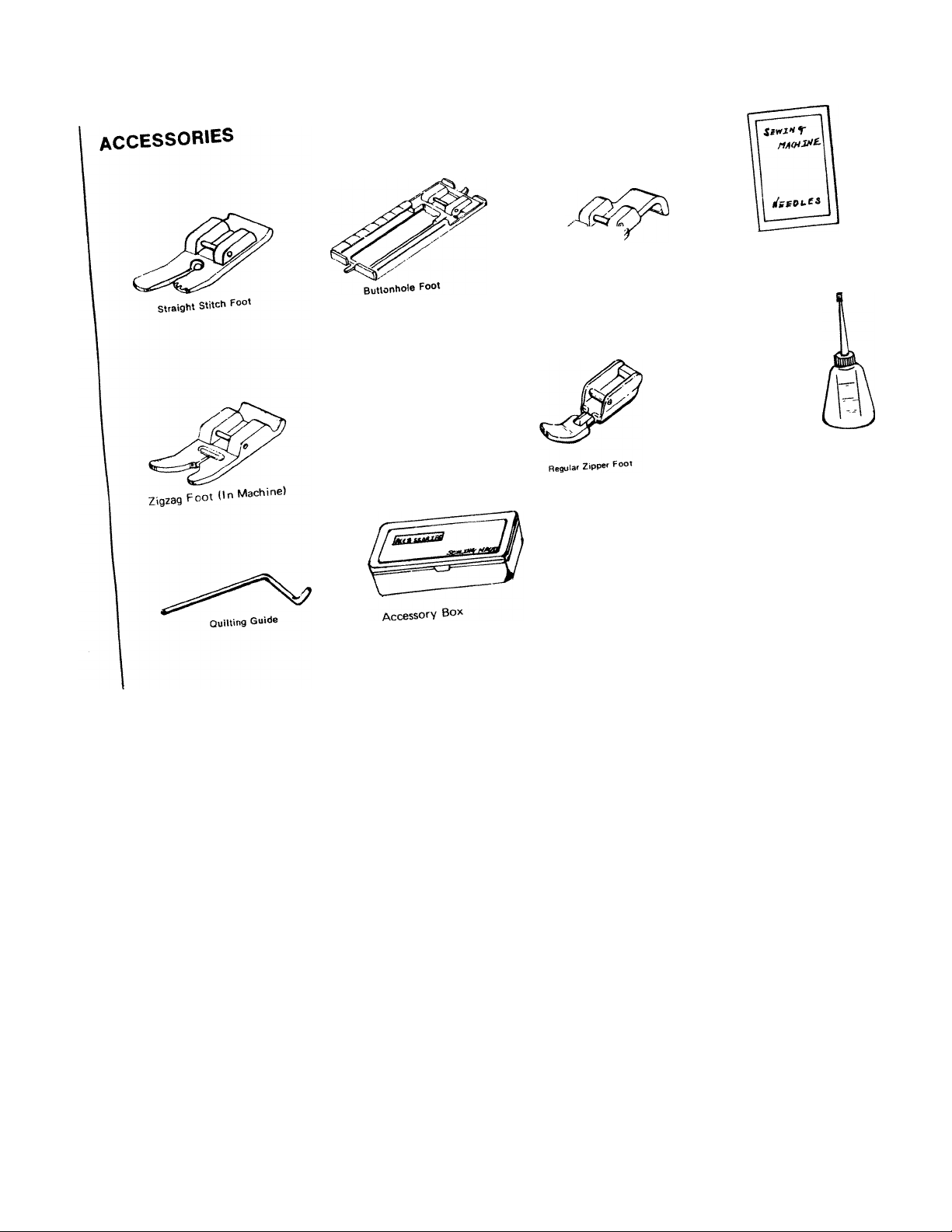
Button
Foot
Needles
Fetts
Bobbins
Seam Rippßt
screw Drivers
Oiler
Page 4
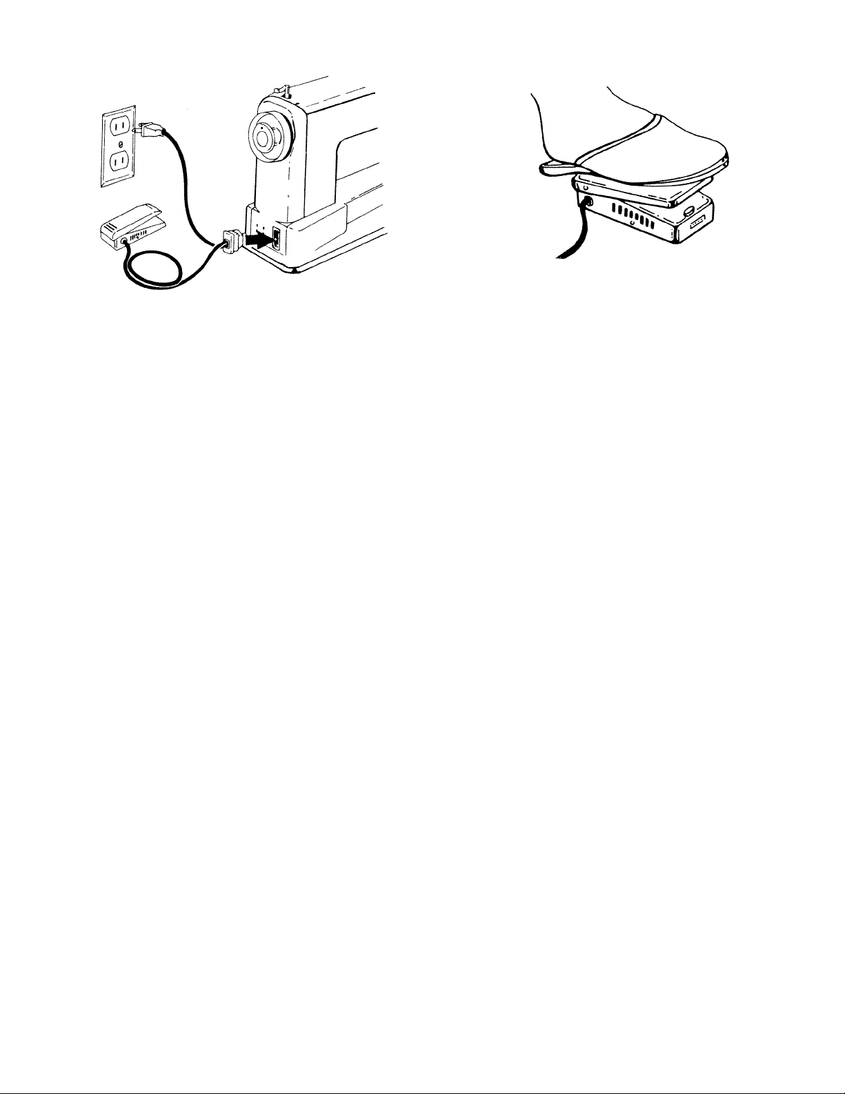
USING THE FOOT CONTROL
TO CONNECT THE FOOT CONTROL WIRES:
• Connect special plug to block on machine as
shown in diagram above.
• Connect outlet plug to electrical outlet.
• When sewing, keep children’s hands away from
foot control.and wiring.
• After sewing, disconnect plug from electrical
outlet.
TO USE THE FOOT PEDAL:
• Begin sewing by turning the hand wheel toward
you and apply gradually increasing pressure to
foot pedal.
• Sewing at a constant speed will give best results.
Page 5
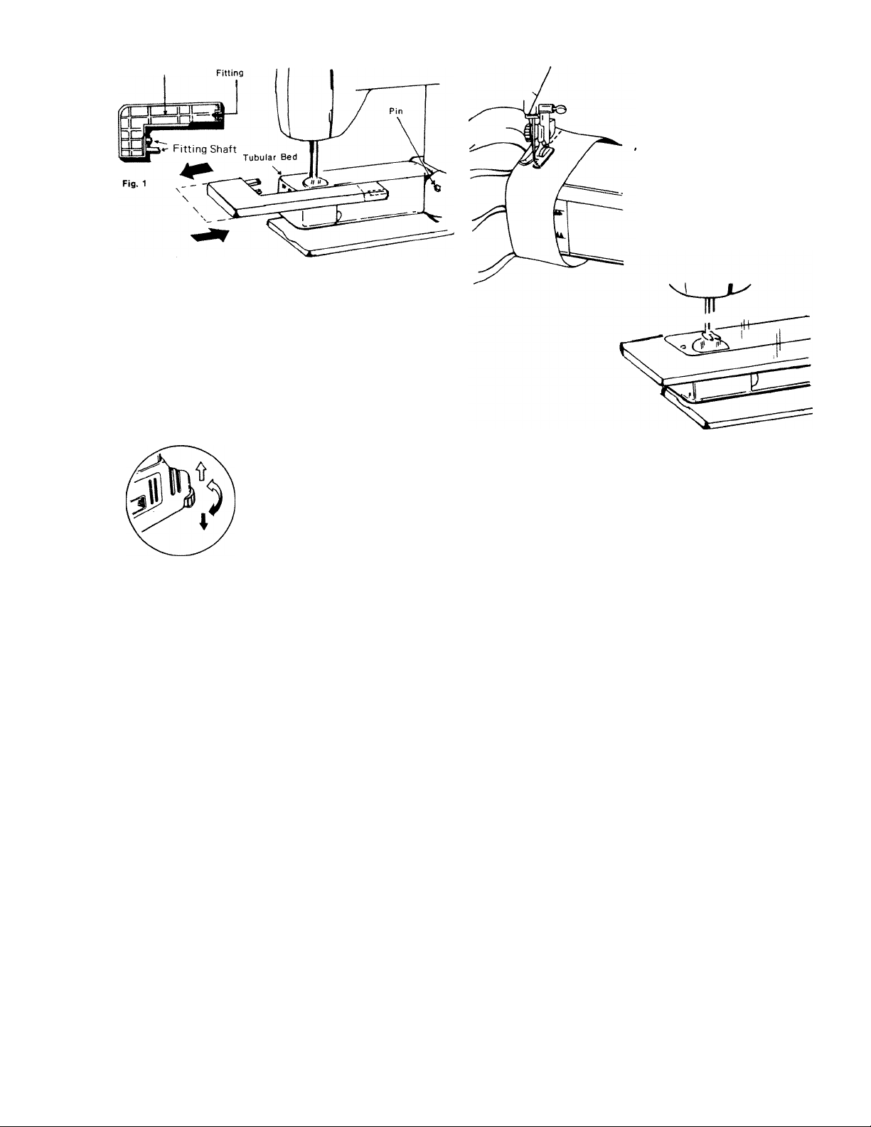
USING THE EXTENSION PLATE
Extension Plate
Fig. 2
TO ATTACH AND REMOVE THE EXTENSION PLATE:
• By sliding extension plate on tubular bed, as
shown in Fig. 2, engage fittings on plate with pin
on tubular bed, and pull to the left to remove the
extension plate.
LEVELING THE MACHINE
Level your sewing machine
when you use it on the table or
install it into the cabinet.
UP: Counter-Clockwise
DOWN: Clockwise
FREE ARM FEATURES
TUBULAR SEWING
• The free arm design
simplifies the sewing of
tubular items such as
pant cuffs, shirt and
blouse cuffs and socks.
Simply position these items
over the tubular bed of
the machine and sew.
FLAT BED SEWING
• When the extension plate is attached, you have
all the advantages of a flat bed machine for
sewing flat items, and for sewing large tubular
items such as flared pant legs.
Page 6
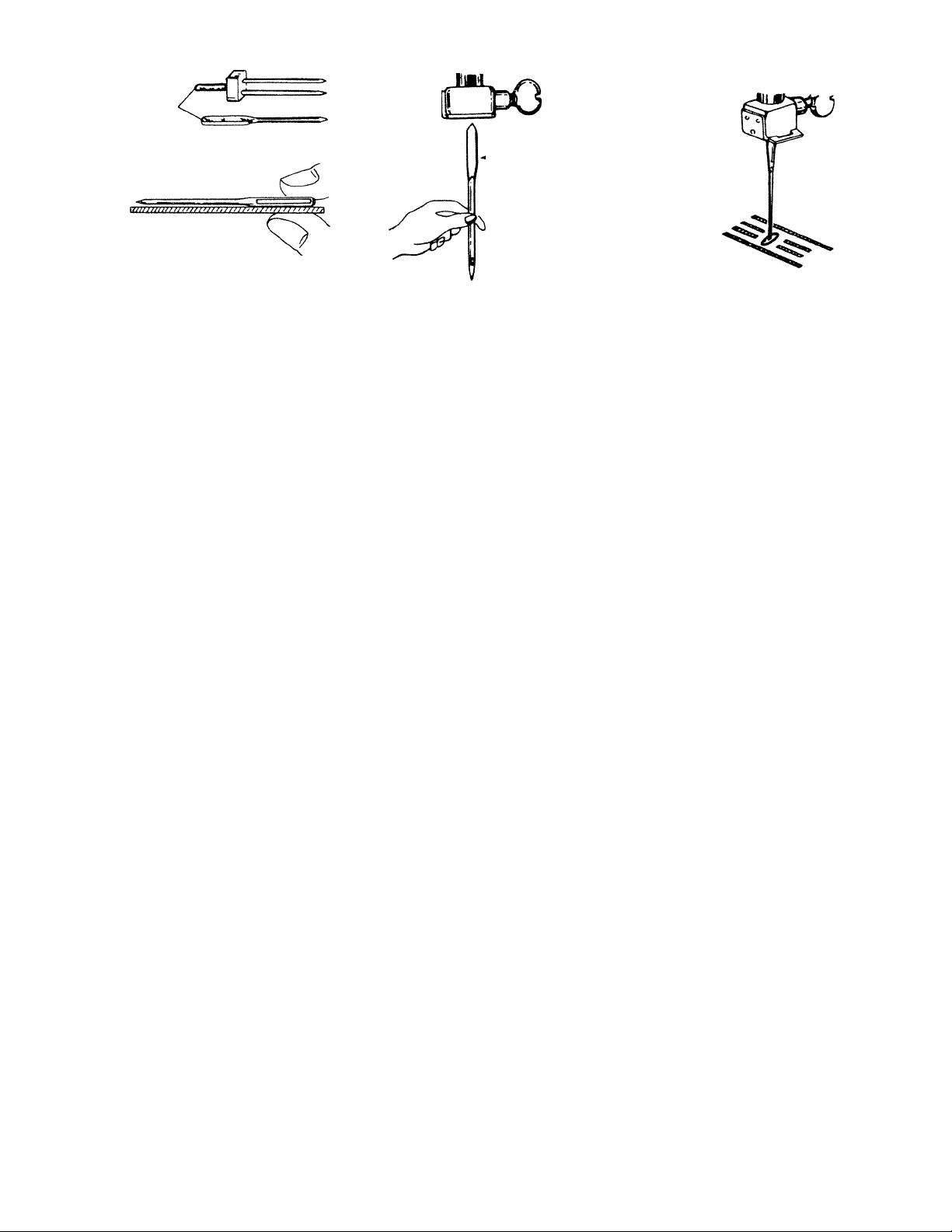
CHANGING THE NEEDLE
Flat side
Always make sure needle is
straight.
To check straightness of
needle, lay needle on a flat
surface and see that needle is
straight and parallel as shown
in above diagram.
• Needle
Clamp Screw
Flat side towards
back of machine
• Turn hand wheel toward you to
raise needle bar to its highest
position.
• Loosen needle clamp screw
and insert needle upward as
far as it will go, making sure
flat side of needle is towards
back of machine as shown
in the above diagram.
• Tighten needle clamp screw
with screwdriver.
• Follow the same procedure for
insertion of twin needle.
To make sure that needle has
been inserted correctly, turn
hand wheel toward you and
see that needle comes down
through the center of the
needle hole in the needle plate
as shown in the above diagram.
Stitch selector dial must be set
in straight stitch needle posi
tion when checking needle
alignment.
If skipped stitches occur, needle
may be incorrectly inserted.
Page 7
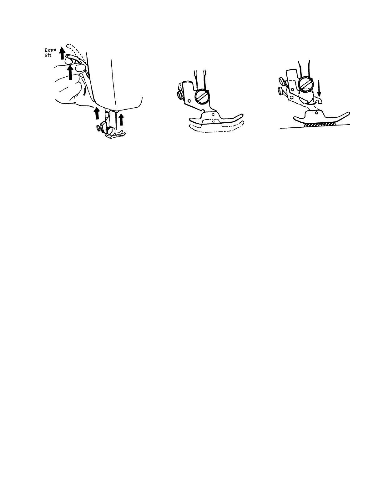
CHANGING THE PRESSER FOOT
Raise needle lis'
position and raise presser tooi
as shown. .
The extra lift for heavy fabric
makes it easier to place fabric
under the presser foot.
TO REMOVE THE PRESSER FOOT.
. Press button '
foot shank and foot wiH drop
from shank as shown above.
I It is not necessary to loosen
the thumb screw to change
presser foot.
TO ATTACH
THE PRESSER FOOT.
• Align desired presser foot to
shank as shown above.
• Lower presser p
shank will automatically attacn
to foot as shown above.
Page 8
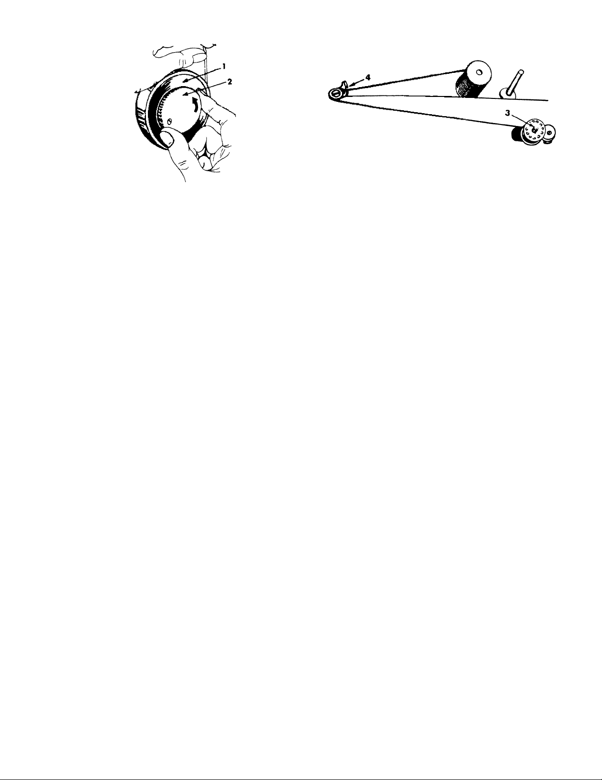
WINDING THE BOBBIN
TO DISENGAGE THE HAND WHEEL:
• Hold the hand wheel (1) with left hand, turn
clutch (2) counterclockwise with right hand to
disengage as shown.
TO WIND THREAD ONTO BOBBIN:
• Lead thread through spring thread guide (4) and
through the hole in your bobbin from the inside
out.
• Place the bobbin onto the bobbin winder shaft
(3).
• Push the bobbin winder to the right.
• Hold loose end of thread firmly and turn hand
wheel to make thread tight. Apply gradual
pressure on foot pedal until automatic shut off
disengages bobbin winder.
• Cut off loose end of thread.
Page 9
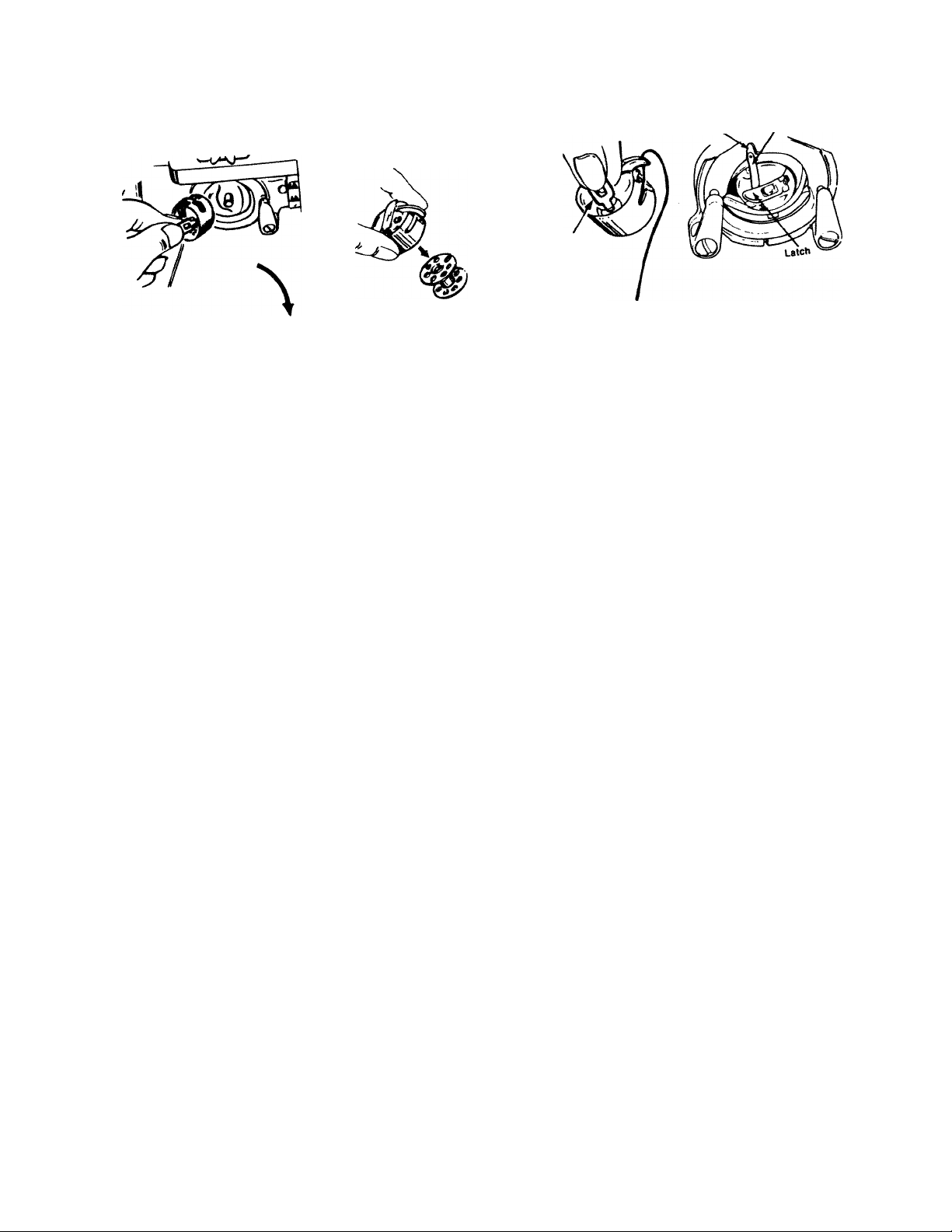
CHANGING BOBBINS
TO REMOVE THE ”e°rpoStoii, Bobbin
With two fingers ana I
. ieCvfbobbln 1,0. bobbin case by releasing
Satch.
Notch
Latch
»f-TArM THE BOBBIN CASE:
TO ATTACH THt . from bobbin.
Finget
. Pull thread at least 3 inches i
, Thread bobbin as highest
. Making sure into shuttle race by
nn«;ition insert boDui Make sure bobbin
ac <;hOWn on p3Q®
KoSng bobbin case p„ss bobbin
case trngons insirla shojue^^^.^ ,,,
cScheion P°tt b' «’b
Page 10
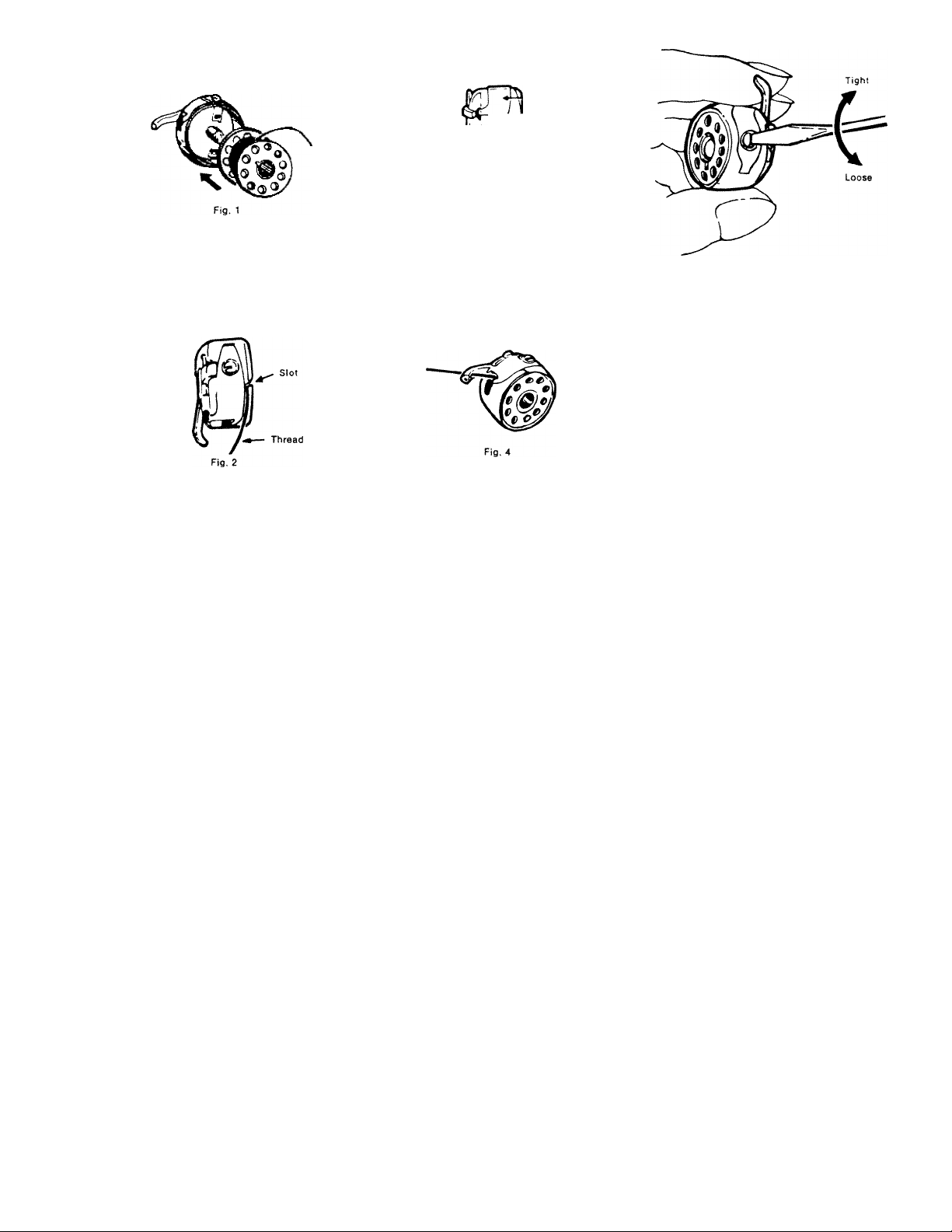
THREADING THE BOBBIN CASE
Pull thread at least 3 inches from
bobbin. Insert bobbin in bobbin
case so that thread will unravel
clockwise.
■ Tension Spring
Fig. 3
Draw thread under the tension
spring and into the fork-shaped
opening of the spring as shown
in Fig. 3.
Fig. 5
TO ADJUST BOBBIN TENSION:
• Turn screw on side of bobbin
case clockwise to increase
tension.
• Turn screw on side of bobbin
case counterclockwise to
decrease tension.
Pull thread into slot of bobbin
case as shown in Fig. 2.
Pull thread through hole in
bobbin case finger as shown in
Fig. 4. (Recommended for
zigzag sewing only)
Page 11
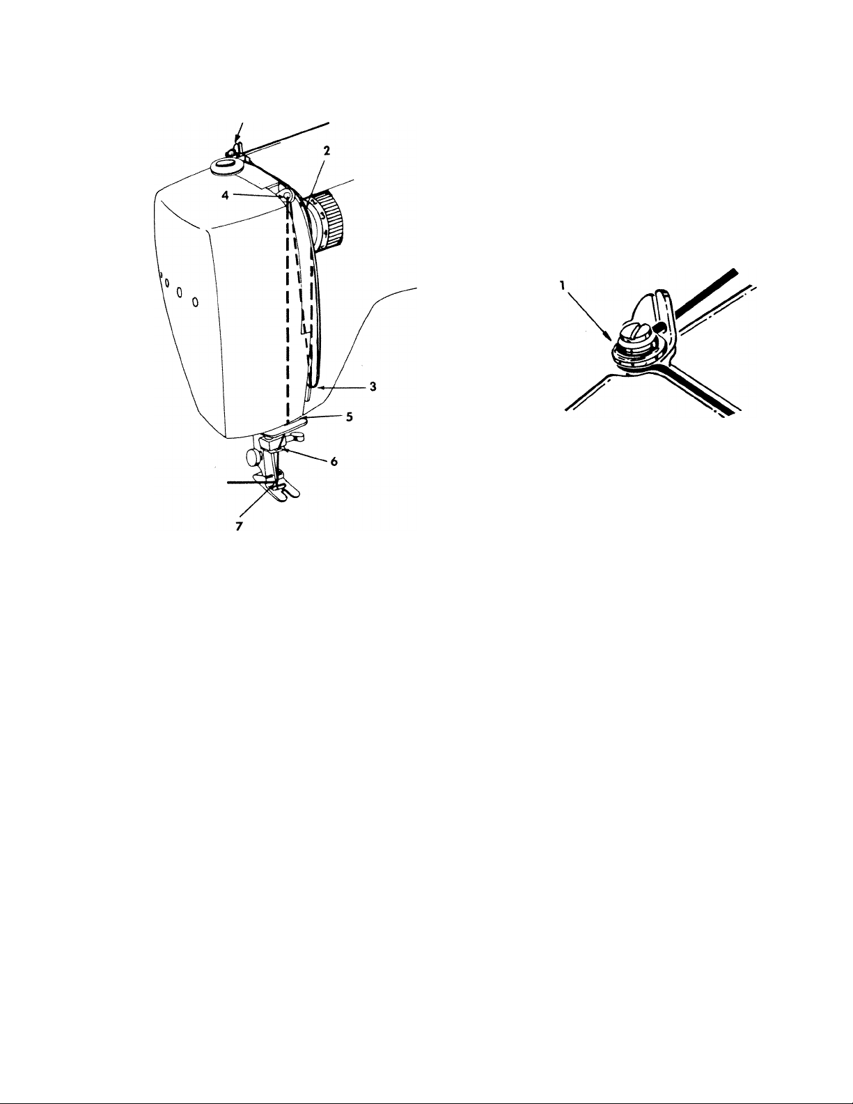
UPPER THREADING
Raise needle batto its highest position.
Ltdre"gh top p,a.e.htead guide ,1,
rti,ra“Srat"ounda;.threadguide(3,
Mt hooking thread into guide.
’ ^¿trou1htredleS'irrrn1;o^^^^
,,„avs use
bottom as different sizes or xypc
r“" T'°PoC«“'ead on the bobbin and
L“Z,bread on top will result in poor tension
quality.
10
Page 12

(TWIN NEEDLE UPPER THREADING)
• Follow threading instruction for single needle with
these exceptions.
• Place thread, matching or contrasting in color, on
both spool pins.
• Draw threads through thread guides as normal, but
separate the threads at the tension.
• Pass thread through the left disc and one thread
through the right disc.
• Now treat both threads as one until you reach the
needle eyes.
ZIGZAG DIAL: Set at desired width between "0" and
"3", if you set dial higher than 3, the needle will hit the
needle plate and break.
STITCH LENGTH: Set at desired stitch length.
ADJUSTING FEED DOG HEIGHT
M
Upper position of feed dog is used for normal sewing.
To raise feed dog.
Press drop feed button "-Allocated under shuttle cover,
to upper position.
Lower position is used for Embroidering, Mending or
Sewing on Button. Press drop feed button to
lower position.
11
Page 13

PICKING-UP LOWER BOBBIN THREAD REGULATING PRESSURE
Holding upper thread, turn hand wheel toward
you one rotation. When take-up lever is at its
highest position, pull thread to pick up loop of
lower bobbin thread.
Pull both upper and lower
thread "to the left of"
presser foot approximately
6 inches.
This will prevent jamming.
' The amount of pressure that is applied to the
fabric by the presser foot is adjusted by the
pressure cap (1). The upper position gives the
least amount of pressure while the lowest position
gives maximum pressure.
To increase the pressure, push down on the
pressure cap to obtain the desired setting. To
decrease the pressure, press down on the snap
lock ring (2) to allow the pressure cap to return
to its maximum height. Then reset to the proper
pressure.
Normally the pressure cap will be in the lowest
position. If the top layer of fabric tends to push
out further than the bottom layer of fabric,
Pressure should be decreased. This often happens
on bulky fabrics, such as wools, and on knits.
12
Page 14

ADJUSTING UPPER TENSION
Fig. t
Proper Tension
Fig. 2
Upper Thread Tension Too Loose
Fig. 3
Upper Thread Tension Too Tight
To increase upper tension, turn upper tension
regulator to higher number.
To decrease upper tension, turn upper tension
regulator to lower number.
Turning tension regulator from "0” to “9” will
increase tension. Normal sewing is performed
between “4” and “5”.
Note; Normal stitches will be performed on the red
zone at 4, 5 and 6 for regular cotton threads.
A perfect straight stitch will be formed with both
threads interlocking in fabric as shown in Fig. 1.
When using the zig zag stitch for embroidery
(satin stitching), decrease upper tension so that
top surface will look smooth at the expense of the
bottom surface.
13
Page 15

STITCHJ^NGTH^^
fabric
________________
~~~~ Z ~ u Z \ace, organdy,
------taf_feta_
_ : ,;rsev. double knit power n^ ^ ^
suits __ __ _ — — —
MED!U|«i^ings^ w^^^^ ^ -
I denim, ^ ^ —
■""^-7akefurs^vel^rs^swe^«^__ _ ^ '
— — ”” ”” ,ar rtfit
needle (Long Scarf) 1 tHBEAD
130/705H
HA X 1 European
Fine
65/9 '
light ball point.
~T^ I
light ball point
Wedge point
90/14 I ^
light or medium
ball point
Wedge point
Toofii"~|
Wedge point
heavy ball point
Wedge point
I ■•A" Silk
point
European 50
Fine Synthetics
Finemercedzed60
European 50 'u
I Fine Synthetics
I •■A" Silk
1
Mercerized M
1 European JU
» "A‘* Silk
i Synthetic
liS'Cr
I European 30
"A" Silk
1 Synthetic
, Heavy Duty Mercerized I
European 30
I Synthetic
STITCH LENGTH
1-1/4 - 1-3/^
1-3/4-2
2-1/2 -3
2-1/2 -4
vinyls, plastics
14
Page 16

FUNCTIONS OF CONTROLS
NEEDLE POSITION AND
PATTERN SELECTOR DIAL
• Raise needle bar to highest
position by turning hand wheel
toward you.
• Select desired pattern and
needle position.
• Selector dial can be turned
either clockwise or counter
clockwise.
ZIGZAG WIDTH CONTROL DIAL
• For wider zigzag stitch,
select a higher number.
• When twin needle is used,
zigzag must be limited between
positions “0” and "3” on the
dial (use of twin needle in
position higher than “3” will
result in needle striking
needle plate).
STITCH LENGTH CONTROL DIAL
• Numbers on dial denote
length of stitches.
• To increase length of stitch,
turn dial to higher number.
STITCH LENGTH GUIDE
Numbers
on dial
Stitches
per inch
0 1 2 3
No
24
Feed
12 8
4
6
REVERSE STITCH BUTTON;
• Use for reverse stitching or
tacking.
• Keeping button pressed in will
allow you to sew reverse stitch
at same length as forward
stitch.
15
Page 17

SELECTING NEEDLE POSITION
Right
• Three different needle positions, " 1 " left,'' 2 " middle
and 3 right can be selected. Also, those intermediate
positions between left and middle and right can be
selected with the dial at the middle between '' 1 2 ",
and "2 3" as shown Above.
1 - - - indicates the left hand needle position
2 - - - indicates the m i ddle needle position
3 indicates the right hand needle position
Middle
Left
STRAIGHT STITCHING
Stitch Length
Control Dial
Set the stitch length control dial to the desired
stitch length (0—4).
Set the zigzag width control knob to "O"
position.
Set the needle position dial to "2 " position.
Straight Stitch
Presser Foot
16
Page 18

CHANGING
DIRECTION OF SEWING:
REMOVING
THE MATERIAL:
CROSSING
HEAVY SEAMS:
• Before changing direction,
stop the machine at the desired
point making sure that the
needle is down through the
fabric.
• Raise the presser foot, turn
the fabric to the desired posi
tion, lower the presser foot
and continue sewing.
Note: When sewing with a twin
needle, it is necessary to raise
the needles above the fabric
before turning. Be cautious to
realign the fabric to the position
where the last stitch ends.
• After stopping the machine,
turn the hand wheel toward you
until the take up lever is at its
highest position.
• Raise the presser foot, then
draw the fabric gently to the
left rear of the machine, making
sure that the threads are under
the foot. This avoids bending
the needle.
• With two hands, lift the two
threads up and into the thread
cutter on the presser bar and
pull down firmly to cut the
threads.
17
When crowing heavy seams,
angle the fabric down into the
foot so that the foot can draw
the heavy area into the feeding
mechanism and pass over the
bulk easily.
Page 19

ZIGZAG STITCHING
Zigzag Foot
(single needle sewing)
• Set the needle position dial in the free position.
• Set the zigzag width control knob from 1 to 5.
• Set the stitch length control dial from 1 to 4.
• Now you can start sewing as you wish.
SINGLE NEEDLE ZIGZAG STITCH PATTERNS
Patterns
WVWvW
mmmmm
wmA/mv
I
Needle Position
Left, Middle
or Right
Left, Middle
or Right
Left, Middle
or Right
Left 1
Middle 2
Right 3
Left 1
Middle 2
Right 3
Stitch Length
Long
Short
Long and Short
(Repeat)
Long
Short
Single Needle Sewing
Zigzag Width Control Dial
Zigzag Width
Any point from 1 to 5
Set the indicators of
zigzag width restricting
knob 0 and 5. Gradually
move from 0 to 5 and
return to 0. (Repeat)
Zigzag width can be
regulated by zigzag
width control. Turn
quickly the control
alternately.
18
(twin needle sewing)
ZIGZAG DIAL:
Set at desired width between 0 and 3.
If you use beyond 3, needle hits the
needle plate and breaks.
STITCH LENGTH:
Set at desired stitch length.
Note: Upper threading for twin needle is
followed same way as single needle
Needle Position: Set at " 1 "
left hand needle position.
Page 20

THREE STEP ZIGZAG STITCHING
Pattern Selector and
Zigzag Width Control Dial
Stitch Length
Control Dial
VARIOUS USES:
• Stitch length should depend on the type of fabric being used.
Short stitch length for flat or woven fabrics and longer for dense
fabrics and knits.
• Mending a tear - guide the tear along the center of the pressure
foot so that stitches catch evenly on both sides. A reinforcing
fabric (interfacing) may be used underneath if desired.
• Use the same technique to make a butted seam for interfacing
such as in the inside of a collar.
• Three step zigzag for overcasting provides a smoother edge than
the regular zigzag. Length-1 Width 1-1/2.
• Understitching facings with the three step zigzag provides less bulk
and facings lie flat on the inside of garments.
• Patches are applied more permenantly with the three step zigzag.
Make patches round where possible or overlap corner stitching to
reinforce corners.
19
Page 21

BLIND STITCHING
Zigzag Foot
Blind Hem
Pattern Selector and
Zigzag Width Control Dial
Stitch Length
Control Dial
rs°e?fhe“conirols as shown on the diagram above, and attach the
. S me'’Sdo a'slown and insert into the gaide on the
. Chargee, manoaiiv anti, ne^ie is
St^sf: .a'bric .o,d a,ong the goide of
foot.
• For knits eliminate the first 1 /4 inch fold.
• The blind hem stitch provides a durable hem hmsh
that is almost invisible on garments,drapes.and curtains.
tt done easily with straight or slightly curved herns^^^
With a little practice it will be a very quick and ea y
application and the hem will never need repairing.
20
Page 22

ELASTIC BLIND STITCHING
Zigzag Foot
E lastic Blind Hem
Pattern Selector and
Zigzag Width Control Dial
Stitch Length
Control Dial
PROCEDURE:
• Set the controls as shown on the diagram above, and attach the
proper presser foot.
• Fold the fabric as shown and insert into the guide on the
presser foot.
• Turn hand wheel manually until needle is in the farthest position
to the left and make sure that needle just catches the edge of the
fold. Sew at slower speed, keeping fabric fold along the guide of
foot.
• For knits use the elastic blind hem and eliminate the first
% inch fold.
• The elastic blind hem stitch gives a stretch, durable hem finish
to knit fabrics. The two tiny zigzag stitches enable the hem
to stretch with the fabric.
It may also prevent woven fabrics from raveling.
21
Page 23

ELASTIC TRIPLE STITCHING (STRAIGHT)
I
ill
I
I
Elastic Tripie Straight Stitch
t]
Regular Straight Stitch \
Guide your fabric from the
front. Do not pull or push as
it will cause poor stitching.
Pattern Selector and
Zipzag Width Control Dial
PROCEDURE:
• The elastic triple straight stitch is used when a straight line
of stitching is desired so that seams may be pressed open
(slacks for example).
• This stitch is especialy useful where the tiny zigzag seam
will not hold its shape and the straight stitch will break.
• Apply this stitch to areas of stress on both wovens and knits (crotch
seam and under arm for example).
• Use this stitch for tightly fitted garments that need a lot of stretch,
such as ski pants, girdles and bathing suits.
• If puckering becomes a problem, use the straight stitch foot.
Note: Always fit your garment before seaming with this stitch as this stitch will bury itself
in the fabric and be difficult to remove.
Stitch Length
Control Dial
22
Page 24

ELASTIC TRIPLE STITCHING (ZIGZAG)
Elastic Triple Zigzag Stitch
Guide your fabric from the front.
Do not pull or push as it will cause
poor stitching.
Pattern Selector and
Zigzag Width Control Dial
PROCEDURE:
• A decorative topstitch can be produced with the rick-rack stitch.
Stitch around the structural lines of the garment for a special effect.
• Apply this stitch to areas of stress on both wovens and knits.
• Use narrow width of zigzag as a heavy duty triple stitch for
seams.
• Use medium and wide widths of zigzag for overcasting edges
of seams, facings and hems of heavier weight fabrics such as
terrycloth, and for attaching elastic. Use also for decorative
stitching.
23
Page 25

IKICUI STITCHING
Paper
Pattern Selector and
Zigzag Width Control Dial
Stitch Length
Control Dial
PROCEDURE:
• The tricot stitch is a very useful special ultra-stretch stitch
called smocking.
• Lingerie or tricot seams should only be about 1/8 inch finished
width.
• Fagoting can be achieved by joining the folded edge of two pieces
of fabric together with a gap between them. Use a sheer ftesh
colored piece of fabric underneath to make the fagoting much
stronger and prettier.
• Do the fapting with a piece of paper underneath and remcwe the
paper by hand washing.
24
Page 26

OVERLOOK STITCHING (OVERCASTING)
PROCEDURE:
• Overlook stitching is used for seaming and finishing the cut edge of
knit fabrics, all in one operation.
• This overlook stitch is especially good for stretch fabrics such as
Overcasting
double knit and jersey and will give a firm, neat edge finish.
• For a finished 1/4" seam, guide your fabric at the right hand
edge of the needle hole as shown.
• When your pattern calls for a 5/8" seam allowance, guide your
fabric along the 1/2" guide line on the needle plate and sew your
seam. Then trim off the excess fabric close to the stitching. On
some fabrics this method is preferable.
Note: The three step zigzag stitch can also be used for overcasting.
Pattern Selector and
Zigzag Width Control Dial
Three Step Zigzag Overcasting
25
Page 27

BUTTONHOLE PREPARATION
puH Buttonhole Foot
Seam Ripper
Pattern Selector and
Zigzag Width Control Dial
Stitch Length
Control Dial
PROCEDURE:
• Attach buttonhole foot to machine with red markings to the left.
• Always make a sample buttonhole on the same fabric us^ to make
your garment. Use a double layer of fabric with interfacing
between.
• Mark the starting and ending position of your buttonholes with
tape and use chalk to mark the cutting line.
• Pull buttonhole box forward until it is fully extended and position
over tape as shown above.
• Proceed as on page 27 "Sewing Buttonholes".
• If buttonhole appears uneven, turn stitch length dial until the left
side looks like the right side. The reverse stitching is pre-set.
• INVISIBLE BUTTON HOLE may be made by using matching
thread so that the button hole blends with the fabric.
• EXAGGERATED BUTTONHOLE may be made by running through
the buttonhole cycle a second time to make a very dense buttonhole.
To add an extra beauty to buttonholes, use a constrasting thread
color.
Example: Red buttonholes on white fabric.
• If buttonholes appear too dense for knit fabrics, release the presaire
cap half way.
26
Invisible
Exaggerated
Page 28

BUTTONHOLES ON LIGHTWEIGHT OR KNIT FABRICS
Cord String
: r-..
Place cord strung over tab on presserfoot as shown.
After finishing the buttonhole, remove the foot from
the fabric, draw the loop of the cord string up to the
bar tack, tie the loose ends and trim the balance.
Position fabric in sewing area and attach button
hole foot to the machine. Sew the buttonhole so
that stitching covers cord string.
27
Page 29

Button Foot
Other Applications
Needle Position Selector and
Zigzag Width Control Dial
PROCEDURE:
• Set drop feed button "Si" position with the needle position selector
" 1" position.
• Place button under button foot such that the needle is aligned
directly with the left hole in your button. Check alignment by
turning hand wheel and watching needle.
• Bring the needle slightly above the button and turn stitch width
knob until needle aligns with the right hole in the button.
• Run machine slowly and make 7-8 stitches.
• With needle in left hole return zigzag width knob to the "0"
position and make 3—4 stitches to tie off your button.
• Apply the above method to sewing on buttons with four holes, hooKs,
snaps, etc.
28
Page 30

Needle Position Selector and
Zigzag Width Control Dial
PROCEDURE:
• For free-nnotion sewing, press drop feed button,
and press down on outer ring of the pressure regulator
to release pressure completely.
• Place under needle of fabric into an embroidery, a
darning and a monogramming hoop.
• With the width at "O" make 5 or 6 stitches to
reinforce the starting point
• At the desired zigzag width stitch to outline the
design by moving the fabric and hoop in a side
motion. To fill the design, move the fabric and
hoop from side to side in a rhythmic motion.
• To return feed to normal, press drop feed
button, and push down on the pressure cap to
obtain the desired setting.
29
MONOGRAMM ING
Page 31

SEWING ON ZIPPERS
Regular Zipper Foot
Needle Position Selector arKi
Zigzag Width Cor^trol Dial
PROCEDURE:
• Set the needle position at " 1 " or " 3 " as needed
to sew the right side or the left side of zipper
respectively, so that the foot sews very close to
the zipper teeth. (Fig. 1)
• Set the needle position at " 3 " and make the
welting by sandwiching the cord into a bias
strip of fabric. Stitch close to cord. (Fig. 2)
• Set the needle position at " 1". Sandwich the
welting between two layers of fabric with right
sides together. Stitch a second time. The needle
stitches close to the cord through all thicknesses
(Fig. 3)
Stitch Length
Control Dial
• Attach zipper foot and adjust position depending on which side
of zipper foot you wish to use.
• Open the zipper and place it face down on the back side of the
fabric with the zipper teeth along the fabric edge.
30
Page 32

QUILTING
Needle Position Selector and
Zigzag Width Control Dial
PROCEDURE:
• Insert the quitter guide bar into the notch under the spring on the
shank and adjust the position according to the desired distance
between quilting slams.
• Stitches are easily aligned by guiding the quilter guide along the
previous seam line.
31
Page 33

CARE AND MAINTENANCE
A majority of service calls can be avoided by proper care of your machine. This involves three important
steps.
1. Cleaning - Give your machine a light cleaning after each garment is completed. For light cleaning —
brush lint from feed dogs, needle bar and hook, and oil hook. A more extensive cleaning and oiling
can be done every two months.
2. Oiling - Use sewing machine oil only. Do not use any other household oils, as they will eventually
cause problems with the machine. Oil every two months, or more often if machine is in constant use.
3. Proper Use of Needles — Always use the proper needle for your fabric and thread.
Change needles often, as they dull quickly especially on synthetic fabrics.
If you are having a problem, before calling the service man:
1. Check to see that the machine is threaded properly.
2. Replace the needle and make sure it is attached correctly.
3. Be sure that the bobbin is wound evenly.
32
Page 34

CLEANING THE MACHINE
Caution: Before cleaning the machine, be sure to disconnect
the power cord from the wall outlet.
CLEANING AND OILING THE HOOK ASSEMBLY
• Raise the needle bar to the highest position.
• Open the hinged shuttle cover and remove the
bobbin case with bobbin.
• Remove lint or dust with a soft cloth or lint brush.
• Use only the oil in the accessory box.
• Replace bobbin case (See page 8 for
instructions).
CLEANING FEED DOGS
• Lint or dust accumulated between the needle
plate and the feed dogs must be removed to
maintain good operation of the machine.
• Raise the needle bar to the highest position and
remove the needle and presser foot.
• Loosen screw on the bed cover plate and remove
the plate.
• Clean lint and dust from the bottom of the needle
plate and the feed dogs with a lint brush.
• Turn the hand wheel slowly and be sure to clean
all areas.
• Replace the removed plate.
33
Page 35

OILING
OIL
OIL
OIL
OIL
Swing open hinged face plate. Apply one drop of
oil at all points indicated by arrows.
remove the two screws on the top plate and Remove
in the accessory box
OIL
Remove screw on the bed cover plate and apolv
oil while turning the hand wheel. ^ ^
34
 Loading...